EP2910860B1 - Thermostatventilsystem und Verfahren zur Regelung eines Thermostatventils - Google Patents
Thermostatventilsystem und Verfahren zur Regelung eines Thermostatventils Download PDFInfo
- Publication number
- EP2910860B1 EP2910860B1 EP14000632.1A EP14000632A EP2910860B1 EP 2910860 B1 EP2910860 B1 EP 2910860B1 EP 14000632 A EP14000632 A EP 14000632A EP 2910860 B1 EP2910860 B1 EP 2910860B1
- Authority
- EP
- European Patent Office
- Prior art keywords
- temperature
- thermostatic
- closing member
- valve
- valve closing
- Prior art date
- Legal status (The legal status is an assumption and is not a legal conclusion. Google has not performed a legal analysis and makes no representation as to the accuracy of the status listed.)
- Active
Links
Images


Classifications
-
- F—MECHANICAL ENGINEERING; LIGHTING; HEATING; WEAPONS; BLASTING
- F24—HEATING; RANGES; VENTILATING
- F24D—DOMESTIC- OR SPACE-HEATING SYSTEMS, e.g. CENTRAL HEATING SYSTEMS; DOMESTIC HOT-WATER SUPPLY SYSTEMS; ELEMENTS OR COMPONENTS THEREFOR
- F24D19/00—Details
- F24D19/10—Arrangement or mounting of control or safety devices
- F24D19/1006—Arrangement or mounting of control or safety devices for water heating systems
- F24D19/1009—Arrangement or mounting of control or safety devices for water heating systems for central heating
- F24D19/1015—Arrangement or mounting of control or safety devices for water heating systems for central heating using a valve or valves
- F24D19/1018—Radiator valves
-
- G—PHYSICS
- G05—CONTROLLING; REGULATING
- G05D—SYSTEMS FOR CONTROLLING OR REGULATING NON-ELECTRIC VARIABLES
- G05D23/00—Control of temperature
- G05D23/19—Control of temperature characterised by the use of electric means
- G05D23/1925—Control of temperature characterised by the use of electric means using a combination of auxiliary electric and non-electric power
-
- G—PHYSICS
- G05—CONTROLLING; REGULATING
- G05D—SYSTEMS FOR CONTROLLING OR REGULATING NON-ELECTRIC VARIABLES
- G05D23/00—Control of temperature
- G05D23/19—Control of temperature characterised by the use of electric means
- G05D23/275—Control of temperature characterised by the use of electric means with sensing element expanding, contracting, or fusing in response to changes of temperature
Definitions
- the present invention relates to a method for regulating a thermostatic valve in a heat exchanger containing a primary media in order to obtain a desired secondary media temperature.
- the present invention also relates to a thermostatic valve system for regulating the thermal transmission from a heat exchanger containing a primary media.
- thermostatic expansion valve In the technical field of heat exchangers, such as convectors or radiators, there are different solutions to controlling the temperature. Commonly used solutions are the thermostatic expansion valve. Such valves are usually provided with some type of user control, such as a knob or a dial, on which the user sets a desired temperature (the numbers on a dial may represent actual temperatures or relative temperature, for instance numbers 0-6 where 0 is the lowest and 6 is the highest temperature). By turning the dial, a thermostatic element in the valve and a valve stem connected to the thermostatic element are displaced, whereby the flow through the valve is changed, which in turn will change the temperature emitted by the heat exchanger. A portion of the thermostatic element becomes longer when its temperature increases and shorter when its temperature decreases.
- thermostatic expansion valves have a drawback in that the thermostatic elements have tolerances and there may be production deviations from one element to another. Thus, the accuracy of a thermostatic expansion valve may be lower then what would be desirable.
- eTRV electronic thermostatic regulating valve
- eTRV electronic thermostatic regulating valve
- Such valves are battery driven and when the temperature is to be changed the electronics actuate a motor to change the opening of the valve.
- the temperature controlling may be more or less continuous.
- the battery has to be replaced. In a large building with many heat exchangers having eTRV's, such battery replacement may be quite time consuming.
- Such a regulating valve is shown in EP 0 923 013 A1 .
- An object of the inventive concept is to aleviate the drawbacks of the prior art. This and other objects, which will become apparent in the following, are accomplished by a method and a valve system as defined in the accompanying independent claims.
- a thermostatic element may be used in a valve for regulating the temperature, and any long term deviation between a desired temperature and an actual temperature, for instance due to tolerances, can be compensated for by adjusting the position of the thermostatic element or by changing the distance between the thermostatic element and the valve closing member.
- the position of the thermostatic element can be changed accordingly to open the valve to such extent that the temperature deviation is compensated for.
- the deviation is temperature dependent, for instance deviating more at high actual temperatures than low actual temperatures, then the extent of compensation is adjusted to the present conditions, i.e.
- the position of the thermostatic element is moved more at high temperatures than when compensating at lower temperatures.
- Another possibility would be to change the length of connection between the valve closing member and the thermostatic element. In the above example, the valve closing member would be distanced from the thermostatic element more at high temperatures than at low temperatures.
- a method of regulating a thermostatic valve in a heat exchanger containing a primary media in order to obtain a desired secondary media temperature wherein the thermostatic valve comprises a valve closing member connected to a thermostatic element in thermal contact with a secondary media, the length of a portion of the thermostatic element being a function of the temperature of the thermostatic element and thereby indirectly of the secondary media temperature, the method comprising the steps of:
- inventive concept not only compensates for manufacturing tolerances, but can also compensate for inherent disturbances in the fluid distribution system.
- the primary media inside the heat exchanger may be for heating or cooling.
- the heat exchanger may be for heating and/or cooling. It may be in the form of a convector or a radiator etc.
- the heat exchanger could be located in a facilities, such as a room for heating/cooling the room, other possibilities being a heat exchanger which is included in a manufacturing process, such as a chemical process.
- the primary media may be a fluid, such as water or a water/glycol mixture.
- the secondary media may be a fluid, such as ambient air or a fluid, such as water or a water/glycol mixture.
- the step of obtaining a desired value for the secondary media temperature may be implemented in various ways. For instance, it can be in the form of input data from another system which is transferred to a control unit in the present system, the control unit being operatively connected, e.g. via a motor, to the thermostatic element and/or the valve closing member.
- a control unit in the present system
- Such another system could be a Building Management System (BMS) or a mobile phone etc.
- BMS Building Management System
- the desired value could be automatically generated by means of a computer of the BMS.
- the desired value could be obtained from a user interface, such as from an electronic interface, e.g. a control panel, or from a mechanical interface, such as a dial or wheel.
- the step of obtaining a desired temperature value for the secondary media temperature is achieved by entering the desired temperature on a user interface.
- the step of aquiring measured values of the secondary media temperature may be done directly. It may for instance be done by means of a temperature sensor, which may be located near the thermostatic element or at some different place. For instance, if the thermostatic valve is located in one part of a room but it is in another part of the room where you want to have a desired temperature, then the sensor could be placed in that other part of the room.
- the step of compensating the position of the valve closing member includes the steps of translating the temperature deviation into a corrective distance in a direction, and moving the thermostatic element said corrective distance in said direction.
- the step of compensating the position of the valve closing member includes the steps of translating the temperature deviation into a corrective distance in a direction, and changing the distance between the thermostatic element and the valve closing member for compensation of the position.
- the above exemplified compensations of the position of the valve closing member may take into account the sum of errors.
- This errors may include tolerances, built-in disturbances, variations of temperature between location of temperature sensor and the thermostatic element, etc.
- the temperature experienced by the thermostatic element can be the sum of the secondary media temperature (e.g. 20 °C sensed by a temperature sensor in the room) and the heat transfer (e.g. 0.5 °C if the fluid is 40 °C or 3 °C if fluid is 70 °C). Any extra deviation between the desired value and the measured value caused by such heat transfer will automatically be compensated for by the method of the present inventive concept.
- the primary media e.g. fluid such as heating water
- a motor could be adapted to move the thermostatic element, suitably controlled by a control unit. Such a motor could also or alternatively be adapted to move the valve closing member or a linking member between the thermostatic element and the valve closing member.
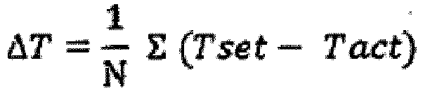
- the corrective distance is determined by continuously and over time measuring the temperature deviation ( ⁇ T) as a function of iterative corrective displacements to the thermostatic element.
- the system may be self-learning and store values in a table. For instance, different degrees of temperature deviation will require different corrective positioning of the valve closing member.
- Such a table may have a linear relationship between that temperature deviation and the corrective distance to be made for the valve closing member, but it could also be non-linear. It may be the case that the temperature deviation is constant or substantially constant, irrespective of the desired secondary media temperature. In such case, it may be enough to once make the correction, i.e. moving the valve closing member said corrective distance. However, in other cases the temperature deviation may vary depending on the desired or measured secondary media temperature.
- the corrective positioning of the valve closing member may have to be changed when a new desired temperature value is obtained.
- the corrective distance or corrective distances may suitably be stored in a compensating table, e.g. in an electronic memory of a control unit.
- the corrective distance is stored in a compensating table based on a previously determined relationship between ( ⁇ T) and the corrective displacement.
- the compensating table is updated over time.
- each one of a number of ranges of desired secondary media temperature has an individual positional compensation for moving the valve closing member an individually defined distance.
- a first temperature range for instance 18.0-19.9°C
- one compensation table may be used, where different temperature deviations ⁇ T are assigned with different corrective distances
- a second temperature range for instance 20.0-21.9°C
- another compensation table may be used, with different relationships between the temperature deviations ⁇ T and corrective distances.
- Said first and second temperature range may be based on the desired secondary media temperature or the measured secondary media temperature.
- the positional compensation is independent of changed values for the desired secondary media temperature.
- the thermostatic element may be operatively connected to a motor.
- the motor may be driven by a control unit.
- the thermostatic valve is connected to or comprises a drive system, including a drive control unit and a drive motor operatively connected to the thermostatic element, wherein the step of compensating the position of the valve closing member is achieved by:
- the thermostatic valve is connected to or comprises a drive system, including a drive control unit and a drive motor operatively connected to the valve closing member or a to a linking member between the valve closing member and the thermostatic element, wherein the step of compensating the position of the valve closing member is achieved by:
- the above drive motor and/or other components such as the drive control unit, may be powered in different ways, e.g. by means of a battery, photo voltaic generator, a Seebeck element, and/or other appropriate power supply.
- the method further comprises the step of supplying energy to the drive system by means of a Seebeck element placed with a first side in thermal contact with the secondary media and a second side in thermal contact with the primary media.
- a "Seebeck element” is also known as a thermoelectric element. It generates a voltage when there is different temperature on each side.
- a thermostatic valve system for regulating the thermal transmission from a heat exchanger containing a primary media, the valve system comprises:
- the control unit adapted to acquire said measured values could be a wall mounted unit, such as a control panel, computer, etc. It could include a temperature sensor or it could receive temperature signals from an external temperature sensor.
- the control unit could communicate, i.e. send and/or receive information, via wires or wireless, e.g. RF, Bluetooth, etc.
- the control unit could be located remotely from a motor which could be used to regulate the position of the valve closing member.
- the control unit could be included in the same housing as said motor.
- the calculation or determination of how much compensation of the position of the valve closing member is appropriate may be performed locally at the thermostatic valve or remotely.
- the thermostatic valve system further comprises:
- the drive motor is an electrically driven motor.
- the movement may be caused by a mechanical, it may be a magnetic, pneumatic, hydraulic or other type of actuation device which can be operatively connected to the thermostatic element, to the valve closing member and/or to a linking member connecting the valve closing member to the thermostatic elements.
- a Seebeck element is adapted to supply energy to the drive system, and wherein the Seebeck element is placed with a first side in thermal contact with the secondary media and a second side in thermal contact with the primary media.
- the Seebeck element and the thermostatic element are placed in two separate compartments inside a housing for the thermostatic valve, the two compartments being thermally insulated from each other.
- the Seebeck element benefits from the proximity to the temperature of the primary media, e.g. heating water, while temperature transfer from the primary media to the thermostatic element in the secondary media is avoided or reduced.
- the thermostatic valve system comprise a user interface for entering the desired value for the secondary media temperature, wherein said user interface is:
- the desired value or preset value of the secondary media temperature may change over time. For instance, in a residential building, one day a user may wish to set 20 °C in the room, but if the user is away for a few days he/she may wish to decrease the temperature to 18 °C.
- the system may for the different settings detect the temperature deviations between the set/desired and the measured values of the temperature and compensate the position of the valve closing member based on the past deviation between the desired values and the respective measured values in order to reduce future deviation.
- the measured values may, for instance, be acquired from a temperature sensor.
- a temperature sensor is located in/on the thermostatic valve.
- the temperature sensor is located in the user interface.
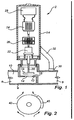
- Fig. 1 is a cross-sectional view, schematically illustrating a thermostatic valve system 2 in accordance with at least one exemplary embodiment of the inventive concept. It should be noted that Fig. 1 is a general schematic representation of a valve system 2 and is merely intended to show an underlying principle of the inventive concept. However, this principle could be used on various types of valve closing members, actuating device etc.
- the valve system 2 comprises a valve body 4 which has a fluid inlet 6 and a fluid outlet 8, and a passage 10 between the inlet 6 and the outlet 8.
- the valve body 4 comprises a partition wall 12 provided with a through-hole 14.
- An area around the through-hole 14 forms a valve seat 16.
- a valve closing member 18, in this embodiment illustrated as a plate (but could be any other suitable type of plug, cone etc.) carried by a valve stem 20, is adjustable in relation to the valve seat 16.
- the valve closing member 18 is connected to a thermostatic element 22 via the valve stem 20.
- linking members e.g. such as the one illustrated in Figs. 5a and 5b , which linking member may allow a relative displacement between the valve closing member and the thermostatic element. This will be further discussed in connection with Figs. 5a and 5b .
- an actuation device 24 is provided for changing the position of the valve closing member 18.
- the actuation device 24 is herein illustrated as a motor, such as an electrically driven motor.
- a gear mechanism 26 converts the rotational motion of the motor 24 to a linear motion of the thermostatic element 22, which in turn displaces the valve closing member 18 in a linear motion.
- a control unit 28 is provided. It may comprise an electronic memory or a database having compensation tables, and may be adapted to receive information about the measured temperature, such as from a separate temperature sensor (not shown), and to receive information about a desired temperature of a secondary media such as ambient air.
- the control unit 28 will control the actuation device 24 to change the position of the valve closing member 18 based on the past deviation ( ⁇ T) between the desired temperature value and measured temperature values in order to reduce future temperature deviation.
- the control unit 28 could be programmed to regularly or in certain time frames compensate, e.g. once a week, the temperature deviation that has been measured since the previous compensation. It is also conceivable to make the compensation on demand, at any given time, wherein the control unit 28 makes its compensation based on the measurements available and their deviations from the desired temperature.
- the control unit 28 has or builds up a database or tables with different correlations and correctional distances of the valve closing member 18 for different conditions, such as different temperature deviations or different desired temperature ranges.
- control unit 28 may, thus, for a given condition make the associated compensation by controlling the actuation device 24 to move the thermostatic element 22 or otherwise change the position of the valve closing member 18. It should be understood that the compensation provided by the control unit 28, is a long term compensation and thus not done frequently. In contrast, the thermostatic element 22 is constantly adapting to changed conditions as a portion thereof automatically expands or shrinks at increased and decreased temperatures, respectively.
- the control unit 28 and/or the actuation device 24 is in this example powered by a Seebeck element 30, which is herein illustrated as being attached to an arm 32 extending from a housing 34, however, other ways of mounting the Seebeck element 30 are conceivable, of course.
- the housing 34 encloses the control unit 28, the actuation device 24, the gear mechanism 26 and the thermostatic element 22.
- the Seebeck element 30 has one side on the valve body 4 which houses the primary media, e.g. heating water, while the other side is in the secondary media, e.g. ambient air.
- the temperature difference between the two sides of the Seebeck element 30 creates a voltage which is enough to power the control unit 28 and the actuation device 24, when needed.
- an accumulator/capacitator (not shown) may be provided for storing excess energy from the Seebeck element 30.
- Fig. 2 is an end view, schematically illustrating at least a further exemplary embodiment.
- a Seebeck element 40 has been illustrated as provided on a housing 42 for the thermostatic element and the other components.
- This schematic drawing is intended to illustrated that the Seebeck element 40 may suitably be arranged at an upper half of the housing 42, where it can be subject to a chimney effect so that secondary media (e.g. air) flows upwards past the Seebeck element 40.
- secondary media e.g. air
- Fig. 3 is a graph illustrating a difference between a desired value for the secondary media temperature and a measured value of the secondary media temperature.
- the upper line represents a desired value of the secondary media temperature, while the lower line represents the measured values of the secondary media temperature.
- the measured values fluctuate somewhat, which can depend on various factors, such as disturbances in the fluid distribution system, load changes, opening/closing of doors/windows, presence or absence of people, machines emitting heat etc.
- t 1 it can be seen that the measured temperature deviated from the desired temperature by approximately four units (a unit is the distance between two horizontal grid lines in the drawing, wherein a unit could represent en integral number of °C or a certain fraction of one or more °C).
- the thermostatic element is moved, or the distance between the valve closing member and the thermostatic element is changed, so that the valve closing member obtains a new position wherein the desired temperature is approached.
- the temperature should be increased four units, i.e. the valve closing member should open the flow passage more to let through more heating fluid, or restrict the flow passage more to let through less cooling fluid.
- a compensating table may be used to determine how much the thermostatic element and/or the valve closing member should be moved for the present deviation.
- Fig. 3 also illustrates that if no compensation has been done during the second time period t 2 , and the desired temperature is increased, the previous deviation of four units will again be present during a third time period t 3 . However, if compensations would be done during each one of said three time periods t 1 , t 2 , t 3 , then the deviation would be likely to decrease for each time period.
- the compensation could be based on long term measurements, for instance including time periods with different desired temperatures, such as the three time periods in Fig. 3 .
- the compensational and positional change of the valve closing member may then be based on an average deviation of the measured values compared to the desired values of the secondary media temperature. It should be understood that rather than making compensations based on an average deviation, the compensation may be made recursively, taking the present deviation and a previous compensation into account.
- Fig. 4 schematically illustrates wireless communication for compensating for temperature deviations, according to at least one exemplary embodiment.
- a fluid distribution system 56 includes a pump 58 for providing fluid to the consumption points 52, 54.
- a remotely located control unit 60 may acquire information about the desired value and actually measured values of the secondary media temperature. Based on the deviations between these values and based on a table which has either been installed at set-up or which has been built-up over time through an iterative learning process by the control unit, the control unit 60 will send a signal to the relevant thermostatic valve system 62 which regulates the consumption point 52 whose temperature needs to be adjusted.
- a receiving unit 64 will convert the signal into a compensating change of position of the valve closing member, so that the desired secondary temperature is approached.
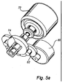
- Figs. 5a and 5b illustrate a linking member 70 for changing the distance between a valve closing member (not shown) and a thermostatic element 72, in accordance with at least one exemplary embodiment of the inventive concept.
- a valve closing member not shown
- a thermostatic element 72 for changing the distance between a valve closing member (not shown) and a thermostatic element 72, in accordance with at least one exemplary embodiment of the inventive concept.
- one way to change the position of the valve closing member may be to use an actuation device which moves the thermostatic element, or a portion thereof.
- the thermostatic element 72 could be fixed and connected via a linking member 70 to the valve closing member (not shown), or a stem of the valve closing member.
- the linking member 70 is illustrated as an internally threaded sleeve 74 in which two oppositely inserted connecting screws 76, 78 have been inserted. This is best seen in the cross-sectional view of Fig. 5b .
- a motor 80 with appropriate gearing 82 (not shown in Fig. 5b ) is operatively connected to the sleeve 74.
- the motor 80 may be controlled by a control unit according to any one of the above exemplified or other embodiments, thereby enabling compensation for temperature deviations between a desired secondary media temperature and a measured temperature.
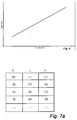
- Fig. 6 is a graph illustrating the length of a portion of a thermostatic element as a function of the temperature of the thermostatic element. As shown in the graph, the relationship is linear. Since the portion of the thermostatic element will have different lengths at different temperatures, the temperature in the secondary media (for instance, room temperature) may deviate from a desired temperature. According to the inventive concept this may be compensated for. An example thereof is conceptually illustrated in Figs. 7a and 7b .
- Figs. 7a and 7b is a schematic illustration of the use of a compensating table according to at least one exemplary embodiment.
- the corrective distance for compensating for the temperature deviation may be determined. This is suitably done by continuously and over time measuring the temperature deviation as a function of iterative corrective displacements to the thermostatic element.
- the system may be self-learning and store values in a table. Such a table is exemplified in Fig. 7a , according to which at different temperatures T1, T2, T3, T4, etc. the length of the portion of the thermostatic element is L1, L2, L3, L4, etc. This relationship is usually known when the thermostatic element is delivered.
- an associated corrective distance C1, C2, C3, C4, etc. may be stored in the table. These values may be updated and fine-tuned over time as more measurement data is captured or if some external conditions or changes in the system occur.
- the corrective distances C1, C2, C3, C4, may be different from each other, however, one or more of them may be the same, depending on the measured temperature deviations.
- the table may have a linear relationship between that temperature deviation and the corrective distance to be made for the valve closing member, but it could also be non-linear.
- the compensating table may suitably be stored in, for instance, an electronic memory of a control unit, such as the control units described above.
- Fig. 7b illustrates schematically how the compensating table may be used.
- a thermostatic element portion 92 is illustrated as being operatively connected to a valve closing member 94.
- the thermostatic portion 92 would have a nominal position X at different temperatures T1, T2, T3, T4, etc.
- a corrective displacement C1, C2, C3, C4, respectively, of the thermostatic element portion 92 and the valve closing member 94 is made to compensate the current position of the valve closing member 94.
- the arrows at C3 and C4 are bigger than at C1 and C2, illustrating that in this exemplified compensation table, a larger corrective displacement is needed for measured temperatures T3 and T4 than for T1 and T2.
Landscapes
- Engineering & Computer Science (AREA)
- Physics & Mathematics (AREA)
- Thermal Sciences (AREA)
- Chemical & Material Sciences (AREA)
- Combustion & Propulsion (AREA)
- Mechanical Engineering (AREA)
- General Engineering & Computer Science (AREA)
- General Physics & Mathematics (AREA)
- Automation & Control Theory (AREA)
- Power Engineering (AREA)
- Control Of Temperature (AREA)
Claims (18)
- Verfahren zum Regeln eines Thermostatventils (2) in einem Wärmetauscher, der ein Primärmedium enthält, um eine gewünschte Sekundärmediumtemperatur zu erhalten, wobei das Thermostatventil ein Ventilschließelement (18) umfasst, das mit einem Thermostatelement (22, 72) verbunden ist, das in thermischem Kontakt mit einem Sekundärmedium steht, wobei die Länge eines Abschnitts des Thermostatelements eine Funktion der Temperatur des Thermostatelements und dadurch indirekt der Sekundärmediumtemperatur ist, wobei das Verfahren folgende Schritte umfasst:- Erhalten eines gewünschten Wertes für die Sekundärmediumtemperatur,- Übersetzen dieses gewünschten Wertes in eine entsprechende Position des Thermostatelements auf der Basis der Funktion,- Bewegen des Thermostatelements (22, 72) und des verbundenen Ventilschließelements (18) und/oder Ändern der Distanz zwischen dem Thermostatelement (22, 72) und dem verbundenen Ventilschließelement (18) auf der Basis der entsprechenden Position, dergestalt, dass die Position des Ventilschließelements eingestellt wird und die gewünschte Sekundärmediumtemperatur angenähert wird,- Erfassen gemessener Werte der Sekundärmediumtemperatur, dadurch gekennzeichnet, dass das Verfahren des Weiteren folgende Schritte umfasst:- Kompensieren der Position des Ventilschließelements (18) auf der Basis der früheren Abweichung (ΔT) zwischen dem gewünschten Temperaturwert und gemessenen Temperaturwerten, um eine künftige Temperaturabweichung zu reduzieren.
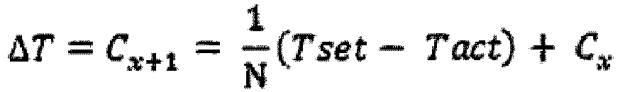
- Verfahren nach Anspruch 1, wobei die frühere Temperaturabweichung ΔT gemäß mindestens einer der folgenden Formeln berechnet wird:

- Verfahren nach einem der vorangehenden Ansprüche, wobei der Schritt des Kompensierens der Position des Ventilschließelements (18) folgende Schritte umfasst:Übersetzen der Temperaturabweichung in eine Korrekturdistanz in einer Richtung, undBewegen des Thermostatelements um die Korrekturdistanz in der Richtung oder Ändern der Distanz zwischen dem Thermostatelement (22, 72) und dem Ventilschließelement (18) zum Kompensieren der Position.
- Verfahren nach Anspruch 3, wobei die Korrekturdistanz durch kontinuierliche Zeitverlaufsmessung der Temperaturabweichung (ΔT) als eine Funktion iterativer Korrekturverschiebungen des Thermostatelements bestimmt wird.
- Verfahren nach Anspruch 4, wobei die Korrekturdistanz in einer Kompensationstabelle auf der Basis einer zuvor bestimmten Beziehung zwischen (ΔT) und der Korrekturverschiebung gespeichert wird.
- Verfahren nach Anspruch 5, wobei die Kompensationstabelle im Lauf der Zeit aktualisiert wird.
- Verfahren nach einem der vorangehenden Ansprüche, wobei im Lauf der Zeit neue Werte für die gewünschte Sekundärmediumtemperatur erhalten werden und wobei jeder aus einer Anzahl von Bereichen gewünschter Sekundärmediumtemperaturen eine individuelle Positionskompensation für das Bewegen des Ventilschließelements um eine individuell definierte Distanz hat.
- Verfahren nach einem der vorangehenden Ansprüche, wobei die Positionskompensation unabhängig von geänderten Werten für die gewünschte Sekundärmediumtemperatur ist.
- Verfahren nach einem der vorangehenden Ansprüche, wobei der Schritt des Erhaltens eines gewünschten Temperaturwertes für die Sekundärmediumtemperatur durch Eingeben der gewünschten Temperatur auf einer Benutzerschnittstelle ausgeführt wird.
- Verfahren nach einem der vorangehenden Ansprüche, wobei das Thermostatventil (2) mit einem Antriebssystem verbunden ist oder ein Antriebssystem umfasst, das eine Antriebssteuereinheit (18) und einen Antriebsmotor (24, 80), der mit dem Thermostatelement (22, 72) wirkverbunden ist, aufweist, wobei der Schritt des Kompensierens der Position des Ventilschließelements ausgeführt wird durch:Empfangen der Korrekturdistanz in der Antriebssteuereinheit, Übersetzen der Distanz in eine Bewegung, die durch den Antriebsmotor verlangt wird, undAktivieren des Antriebsmotors, um das Thermostatelement um die Korrekturdistanz in der Richtung zu bewegen.
- Verfahren nach Anspruch 10, das des Weiteren den Schritt umfasst, das Antriebssystem mittels eines Seebeck-Elements (30), das mit einer ersten Seite in thermischem Kontakt mit dem Sekundärmedium und mit einer zweiten Seite in thermischem Kontakt mit dem Primärmedium steht, mit Energie zu versorgen.
- Thermostatventilsystem zum Regeln der Wärmeübertragung von einem Wärmetauscher, der ein Primärmedium enthält, wobei das Ventilsystem Folgendes umfasst:ein Ventilschließelement (18), das mit einem Ventil dergestalt verbunden ist, dass eine Verschiebungsdistanz des Ventilschließelements (18) den Grad der Öffnung des Ventils bestimmt, undein Thermostatelement (22, 72), das mit dem Ventilschließelement dergestalt verbunden ist, dass eine thermische Ausdehnung oder Schrumpfung eines Abschnitts des Thermostatelements (22, 72) eine Bewegung zu dem Ventilschließelement (18) überträgt,ein Mittel zum Erhalten eines gewünschten Wertes für eine gewünschte Sekundärmediumtemperatur,ein Mittel zum Erhalten gemessener Werte der Sekundärmediumtemperatur,dadurch gekennzeichnet, dass es des Weiteren Folgendes umfasst:eine Steuereinheit (28), die dafür ausgelegt ist, die gemessenen Werte der Sekundärmediumtemperatur zu erfassen und die Position des Ventilschließelements (18) auf der Basis der früheren Abweichung zwischen dem gewünschten Wert und gemessenen Werten zu kompensieren, um eine künftige Abweichung zu reduzieren.
- Thermostatventilsystem nach Anspruch 12, das des Weiteren Folgendes umfasst:ein Antriebssystem, das mit der Steuereinheit (28) verbunden ist oder die Steuereinheit (28) aufweist und mit einem Antriebsmotor (24, 80) verbunden ist oder einen Antriebsmotor (24, 80) aufweist, der mit dem Thermostatelement (22, 72) wirkverbunden ist und dafür ausgelegt ist, die Position des Thermostatelements (22, 72) und/oder die Distanz zwischen dem Thermostatelement (22, 72) und dem Ventilschließelement (18) zu ändern;wobei die Steuereinheit (18) dafür ausgelegt ist, die Temperaturabweichung in eine Korrekturdistanz in einer Richtung zu übersetzen und den Antriebsmotor (24, 80) zu veranlassen, das Thermostatelement (22, 72), das Ventilschließelement (18) und/oder ein Verbindungselement (170), welches das Ventilschließelement (18) mit dem Thermostatelement (22, 72) verbindet, um die Korrekturdistanz in der Richtung zu bewegen.
- Thermostatventilsystem nach Anspruch 13, wobei der Antriebsmotor (24, 80) ein elektrisch angetriebener Motor ist.
- Thermostatventilsystem nach einem der Ansprüche 13-14, wobei ein Seebeck-Element (30) dafür ausgelegt ist, das Antriebssystem mit Energie zu versorgen, und wobei das Seebeck-Element (30) mit einer ersten Seite in thermischem Kontakt mit dem Sekundärmedium und mit einer zweiten Seite in thermischem Kontakt mit dem Primärmedium steht.
- Thermostatventilsystem nach Anspruch 15, wobei das Seebeck-Element (30) und das Thermostatelement (22, 72) in zwei separaten Abteilen im Inneren eines Gehäuses (34) für das Thermostatventil angeordnet sind, wobei die zwei Abteile thermisch voneinander isoliert sind.
- Thermostatventilsystem nach einem der Ansprüche 12-16, das eine Benutzerschnittstelle zum Eingeben des gewünschten Wertes für die Sekundärmediumtemperatur umfasst, wobei die Benutzerschnittstelle:an dem Thermostatventil (2) montiert ist oderin einer räumlich abgesetzten Position in Bezug auf das Thermostatventil angeordnet ist, wie zum Beispiel in Verbindung mit einer Steuervorrichtung eines Gebäudemanagementsystems (GMS) oder einer dedizierten Steuertafel, oder als ein Drahtloskommunikationsgerät, wie zum Beispiel ein Mobiltelefon, ein Computer oder eine Fernbedienung, ausgeführt ist.
- Thermostatventilsystem nach einem der Ansprüche 12-17, wobei sich ein Temperatursensor in oder auf dem Thermostaten oder in der Benutzerschnittstelle befindet.
Priority Applications (1)
| Application Number | Priority Date | Filing Date | Title |
|---|---|---|---|
| EP14000632.1A EP2910860B1 (de) | 2014-02-22 | 2014-02-22 | Thermostatventilsystem und Verfahren zur Regelung eines Thermostatventils |
Applications Claiming Priority (1)
| Application Number | Priority Date | Filing Date | Title |
|---|---|---|---|
| EP14000632.1A EP2910860B1 (de) | 2014-02-22 | 2014-02-22 | Thermostatventilsystem und Verfahren zur Regelung eines Thermostatventils |
Publications (2)
| Publication Number | Publication Date |
|---|---|
| EP2910860A1 EP2910860A1 (de) | 2015-08-26 |
| EP2910860B1 true EP2910860B1 (de) | 2016-08-24 |
Family
ID=50190144
Family Applications (1)
| Application Number | Title | Priority Date | Filing Date |
|---|---|---|---|
| EP14000632.1A Active EP2910860B1 (de) | 2014-02-22 | 2014-02-22 | Thermostatventilsystem und Verfahren zur Regelung eines Thermostatventils |
Country Status (1)
| Country | Link |
|---|---|
| EP (1) | EP2910860B1 (de) |
Families Citing this family (3)
| Publication number | Priority date | Publication date | Assignee | Title |
|---|---|---|---|---|
| US10551073B2 (en) * | 2017-03-13 | 2020-02-04 | Schneider Electric Controls Uk Limited | Thermostatic actuator for radiator valve and zoned heating system comprising same |
| IT201800002007A1 (it) * | 2018-01-26 | 2019-07-26 | Ivar Spa | Dispositivo e metodo per la regolazione della temperatura di un elemento riscaldante |
| DE102018116485A1 (de) * | 2018-07-06 | 2020-01-09 | Samson Aktiengesellschaft | System zum ausgleichen einer durch thermische belastung einhergehende abmessungsänderung an einer stellarmatur, stellungsregelungssystem, verfahren zum ausgleichen einer durch thermische belastung einhergehende abmessungsänderung an einer stellarmatur und stellarmatur |
Family Cites Families (3)
| Publication number | Priority date | Publication date | Assignee | Title |
|---|---|---|---|---|
| DE19754837A1 (de) * | 1997-12-10 | 1999-07-15 | Danfoss As | Thermostataufsatz für ein Ventil |
| DE102005025501C5 (de) * | 2005-06-03 | 2010-10-21 | Danfoss A/S | Wärmetauscherventil-Steueraufsatz, insbesondere Heizkörperventil-Thermostataufsatz |
| DE102011018698A1 (de) * | 2011-04-26 | 2012-10-31 | Rwe Effizienz Gmbh | Verfahren und System zum automatischen hydraulischen Abgleichen von Heizkörpern |
-
2014
- 2014-02-22 EP EP14000632.1A patent/EP2910860B1/de active Active
Also Published As
| Publication number | Publication date |
|---|---|
| EP2910860A1 (de) | 2015-08-26 |
Similar Documents
| Publication | Publication Date | Title |
|---|---|---|
| US6581847B2 (en) | Variable-air-volume diffuser, actuator assembly and method | |
| US20110166712A1 (en) | Deadband control of pneumatic control devices | |
| US9267694B2 (en) | Method and system for controlling the temperature of components | |
| US6522954B1 (en) | Smart control strategy for regulating a temperature controller | |
| US11306933B2 (en) | Method and device for internet-based optimization of parameters of heating control | |
| CN105849449B (zh) | 阀和操作阀的方法 | |
| US8527099B2 (en) | Pneumatic control device and system | |
| US9921590B2 (en) | Temperature control unit for the heating system in a building | |
| EP2910860B1 (de) | Thermostatventilsystem und Verfahren zur Regelung eines Thermostatventils | |
| EP3276267B1 (de) | Automatische ausgleichsventilanordnung, verfahren zum steuern von wasser-durchfluss und ein computerlesbares medium | |
| WO2012065275A1 (en) | Device and method for controlling opening of a valve in an hvac system | |
| US10527186B2 (en) | Valve flow control optimization via customization of an intelligent actuator | |
| EP0717332A1 (de) | Elektrisches Steuergerät für ein Stellorgan | |
| ES2878139T5 (en) | Heating cost distributor for detecting the amount of heat output by a radiator | |
| US10234155B2 (en) | Method for temperature control | |
| IT201600101195A1 (it) | Sistema di controllo per una rete di distribuzione di gas naturale, rete di distribuzione di gas naturale comprendente tale sistema di controllo e metodo di controllo di tale rete di distribuzione | |
| US20180363801A1 (en) | Hydronic control valve | |
| EP3699718A1 (de) | Ventildurchflussregelungsoptimierung mittels individueller anpassung eines intelligenten aktuators | |
| WO2016174475A1 (en) | An electronic radiator valve regulator, a radiator valve assembly and a radiator control system | |
| EP3382492A1 (de) | Thermostatischer aktuator für heizkörperventil und zonenheizsystem damit | |
| CN101283320A (zh) | 恒温器阀盖 | |
| WO2019145873A1 (en) | Device and method for the temperature adjustment of a heating element | |
| US20260079506A1 (en) | A valve arrangement for controlling fluid flow | |
| Muniak | Regulation Fixtures in Hydronic Heating Installations | |
| US20240353872A1 (en) | Valve metering flow sensor integration |
Legal Events
| Date | Code | Title | Description |
|---|---|---|---|
| PUAI | Public reference made under article 153(3) epc to a published international application that has entered the european phase |
Free format text: ORIGINAL CODE: 0009012 |
|
| AK | Designated contracting states |
Kind code of ref document: A1 Designated state(s): AL AT BE BG CH CY CZ DE DK EE ES FI FR GB GR HR HU IE IS IT LI LT LU LV MC MK MT NL NO PL PT RO RS SE SI SK SM TR |
|
| AX | Request for extension of the european patent |
Extension state: BA ME |
|
| RAP1 | Party data changed (applicant data changed or rights of an application transferred) |
Owner name: IMI HYDRONIC ENGINEERING INTERNATIONAL SA |
|
| 17P | Request for examination filed |
Effective date: 20160209 |
|
| RBV | Designated contracting states (corrected) |
Designated state(s): AL AT BE BG CH CY CZ DE DK EE ES FI FR GB GR HR HU IE IS IT LI LT LU LV MC MK MT NL NO PL PT RO RS SE SI SK SM TR |
|
| RIC1 | Information provided on ipc code assigned before grant |
Ipc: F24D 19/10 20060101AFI20160324BHEP Ipc: G05D 23/19 20060101ALI20160324BHEP |
|
| GRAP | Despatch of communication of intention to grant a patent |
Free format text: ORIGINAL CODE: EPIDOSNIGR1 |
|
| INTG | Intention to grant announced |
Effective date: 20160512 |
|
| GRAS | Grant fee paid |
Free format text: ORIGINAL CODE: EPIDOSNIGR3 |
|
| GRAA | (expected) grant |
Free format text: ORIGINAL CODE: 0009210 |
|
| AK | Designated contracting states |
Kind code of ref document: B1 Designated state(s): AL AT BE BG CH CY CZ DE DK EE ES FI FR GB GR HR HU IE IS IT LI LT LU LV MC MK MT NL NO PL PT RO RS SE SI SK SM TR |
|
| REG | Reference to a national code |
Ref country code: GB Ref legal event code: FG4D |
|
| REG | Reference to a national code |
Ref country code: CH Ref legal event code: EP |
|
| REG | Reference to a national code |
Ref country code: AT Ref legal event code: REF Ref document number: 823463 Country of ref document: AT Kind code of ref document: T Effective date: 20160915 |
|
| REG | Reference to a national code |
Ref country code: IE Ref legal event code: FG4D |
|
| REG | Reference to a national code |
Ref country code: DE Ref legal event code: R096 Ref document number: 602014003156 Country of ref document: DE |
|
| REG | Reference to a national code |
Ref country code: LT Ref legal event code: MG4D |
|
| REG | Reference to a national code |
Ref country code: NL Ref legal event code: MP Effective date: 20160824 |
|
| REG | Reference to a national code |
Ref country code: AT Ref legal event code: MK05 Ref document number: 823463 Country of ref document: AT Kind code of ref document: T Effective date: 20160824 |
|
| PG25 | Lapsed in a contracting state [announced via postgrant information from national office to epo] |
Ref country code: HR Free format text: LAPSE BECAUSE OF FAILURE TO SUBMIT A TRANSLATION OF THE DESCRIPTION OR TO PAY THE FEE WITHIN THE PRESCRIBED TIME-LIMIT Effective date: 20160824 Ref country code: IT Free format text: LAPSE BECAUSE OF FAILURE TO SUBMIT A TRANSLATION OF THE DESCRIPTION OR TO PAY THE FEE WITHIN THE PRESCRIBED TIME-LIMIT Effective date: 20160824 Ref country code: NO Free format text: LAPSE BECAUSE OF FAILURE TO SUBMIT A TRANSLATION OF THE DESCRIPTION OR TO PAY THE FEE WITHIN THE PRESCRIBED TIME-LIMIT Effective date: 20161124 Ref country code: FI Free format text: LAPSE BECAUSE OF FAILURE TO SUBMIT A TRANSLATION OF THE DESCRIPTION OR TO PAY THE FEE WITHIN THE PRESCRIBED TIME-LIMIT Effective date: 20160824 Ref country code: NL Free format text: LAPSE BECAUSE OF FAILURE TO SUBMIT A TRANSLATION OF THE DESCRIPTION OR TO PAY THE FEE WITHIN THE PRESCRIBED TIME-LIMIT Effective date: 20160824 Ref country code: RS Free format text: LAPSE BECAUSE OF FAILURE TO SUBMIT A TRANSLATION OF THE DESCRIPTION OR TO PAY THE FEE WITHIN THE PRESCRIBED TIME-LIMIT Effective date: 20160824 Ref country code: LT Free format text: LAPSE BECAUSE OF FAILURE TO SUBMIT A TRANSLATION OF THE DESCRIPTION OR TO PAY THE FEE WITHIN THE PRESCRIBED TIME-LIMIT Effective date: 20160824 |
|
| PG25 | Lapsed in a contracting state [announced via postgrant information from national office to epo] |
Ref country code: AT Free format text: LAPSE BECAUSE OF FAILURE TO SUBMIT A TRANSLATION OF THE DESCRIPTION OR TO PAY THE FEE WITHIN THE PRESCRIBED TIME-LIMIT Effective date: 20160824 Ref country code: SE Free format text: LAPSE BECAUSE OF FAILURE TO SUBMIT A TRANSLATION OF THE DESCRIPTION OR TO PAY THE FEE WITHIN THE PRESCRIBED TIME-LIMIT Effective date: 20160824 Ref country code: GR Free format text: LAPSE BECAUSE OF FAILURE TO SUBMIT A TRANSLATION OF THE DESCRIPTION OR TO PAY THE FEE WITHIN THE PRESCRIBED TIME-LIMIT Effective date: 20161125 Ref country code: LV Free format text: LAPSE BECAUSE OF FAILURE TO SUBMIT A TRANSLATION OF THE DESCRIPTION OR TO PAY THE FEE WITHIN THE PRESCRIBED TIME-LIMIT Effective date: 20160824 Ref country code: PT Free format text: LAPSE BECAUSE OF FAILURE TO SUBMIT A TRANSLATION OF THE DESCRIPTION OR TO PAY THE FEE WITHIN THE PRESCRIBED TIME-LIMIT Effective date: 20161226 Ref country code: ES Free format text: LAPSE BECAUSE OF FAILURE TO SUBMIT A TRANSLATION OF THE DESCRIPTION OR TO PAY THE FEE WITHIN THE PRESCRIBED TIME-LIMIT Effective date: 20160824 |
|
| PG25 | Lapsed in a contracting state [announced via postgrant information from national office to epo] |
Ref country code: RO Free format text: LAPSE BECAUSE OF FAILURE TO SUBMIT A TRANSLATION OF THE DESCRIPTION OR TO PAY THE FEE WITHIN THE PRESCRIBED TIME-LIMIT Effective date: 20160824 Ref country code: EE Free format text: LAPSE BECAUSE OF FAILURE TO SUBMIT A TRANSLATION OF THE DESCRIPTION OR TO PAY THE FEE WITHIN THE PRESCRIBED TIME-LIMIT Effective date: 20160824 |
|
| REG | Reference to a national code |
Ref country code: DE Ref legal event code: R097 Ref document number: 602014003156 Country of ref document: DE |
|
| PG25 | Lapsed in a contracting state [announced via postgrant information from national office to epo] |
Ref country code: PL Free format text: LAPSE BECAUSE OF FAILURE TO SUBMIT A TRANSLATION OF THE DESCRIPTION OR TO PAY THE FEE WITHIN THE PRESCRIBED TIME-LIMIT Effective date: 20160824 Ref country code: CZ Free format text: LAPSE BECAUSE OF FAILURE TO SUBMIT A TRANSLATION OF THE DESCRIPTION OR TO PAY THE FEE WITHIN THE PRESCRIBED TIME-LIMIT Effective date: 20160824 Ref country code: BG Free format text: LAPSE BECAUSE OF FAILURE TO SUBMIT A TRANSLATION OF THE DESCRIPTION OR TO PAY THE FEE WITHIN THE PRESCRIBED TIME-LIMIT Effective date: 20161124 Ref country code: SM Free format text: LAPSE BECAUSE OF FAILURE TO SUBMIT A TRANSLATION OF THE DESCRIPTION OR TO PAY THE FEE WITHIN THE PRESCRIBED TIME-LIMIT Effective date: 20160824 Ref country code: SK Free format text: LAPSE BECAUSE OF FAILURE TO SUBMIT A TRANSLATION OF THE DESCRIPTION OR TO PAY THE FEE WITHIN THE PRESCRIBED TIME-LIMIT Effective date: 20160824 Ref country code: DK Free format text: LAPSE BECAUSE OF FAILURE TO SUBMIT A TRANSLATION OF THE DESCRIPTION OR TO PAY THE FEE WITHIN THE PRESCRIBED TIME-LIMIT Effective date: 20160824 Ref country code: BE Free format text: LAPSE BECAUSE OF FAILURE TO SUBMIT A TRANSLATION OF THE DESCRIPTION OR TO PAY THE FEE WITHIN THE PRESCRIBED TIME-LIMIT Effective date: 20160824 |
|
| PLBE | No opposition filed within time limit |
Free format text: ORIGINAL CODE: 0009261 |
|
| STAA | Information on the status of an ep patent application or granted ep patent |
Free format text: STATUS: NO OPPOSITION FILED WITHIN TIME LIMIT |
|
| 26N | No opposition filed |
Effective date: 20170526 |
|
| PG25 | Lapsed in a contracting state [announced via postgrant information from national office to epo] |
Ref country code: SI Free format text: LAPSE BECAUSE OF FAILURE TO SUBMIT A TRANSLATION OF THE DESCRIPTION OR TO PAY THE FEE WITHIN THE PRESCRIBED TIME-LIMIT Effective date: 20160824 |
|
| PG25 | Lapsed in a contracting state [announced via postgrant information from national office to epo] |
Ref country code: MC Free format text: LAPSE BECAUSE OF FAILURE TO SUBMIT A TRANSLATION OF THE DESCRIPTION OR TO PAY THE FEE WITHIN THE PRESCRIBED TIME-LIMIT Effective date: 20160824 |
|
| REG | Reference to a national code |
Ref country code: CH Ref legal event code: PL |
|
| PG25 | Lapsed in a contracting state [announced via postgrant information from national office to epo] |
Ref country code: LI Free format text: LAPSE BECAUSE OF NON-PAYMENT OF DUE FEES Effective date: 20170228 Ref country code: CH Free format text: LAPSE BECAUSE OF NON-PAYMENT OF DUE FEES Effective date: 20170228 |
|
| REG | Reference to a national code |
Ref country code: IE Ref legal event code: MM4A |
|
| REG | Reference to a national code |
Ref country code: FR Ref legal event code: ST Effective date: 20171031 |
|
| PG25 | Lapsed in a contracting state [announced via postgrant information from national office to epo] |
Ref country code: LU Free format text: LAPSE BECAUSE OF NON-PAYMENT OF DUE FEES Effective date: 20170222 |
|
| PG25 | Lapsed in a contracting state [announced via postgrant information from national office to epo] |
Ref country code: FR Free format text: LAPSE BECAUSE OF NON-PAYMENT OF DUE FEES Effective date: 20170228 |
|
| PG25 | Lapsed in a contracting state [announced via postgrant information from national office to epo] |
Ref country code: IE Free format text: LAPSE BECAUSE OF NON-PAYMENT OF DUE FEES Effective date: 20170222 |
|
| PG25 | Lapsed in a contracting state [announced via postgrant information from national office to epo] |
Ref country code: MT Free format text: LAPSE BECAUSE OF NON-PAYMENT OF DUE FEES Effective date: 20170222 |
|
| PG25 | Lapsed in a contracting state [announced via postgrant information from national office to epo] |
Ref country code: AL Free format text: LAPSE BECAUSE OF FAILURE TO SUBMIT A TRANSLATION OF THE DESCRIPTION OR TO PAY THE FEE WITHIN THE PRESCRIBED TIME-LIMIT Effective date: 20160824 |
|
| PG25 | Lapsed in a contracting state [announced via postgrant information from national office to epo] |
Ref country code: HU Free format text: LAPSE BECAUSE OF FAILURE TO SUBMIT A TRANSLATION OF THE DESCRIPTION OR TO PAY THE FEE WITHIN THE PRESCRIBED TIME-LIMIT; INVALID AB INITIO Effective date: 20140222 |
|
| PG25 | Lapsed in a contracting state [announced via postgrant information from national office to epo] |
Ref country code: CY Free format text: LAPSE BECAUSE OF FAILURE TO SUBMIT A TRANSLATION OF THE DESCRIPTION OR TO PAY THE FEE WITHIN THE PRESCRIBED TIME-LIMIT Effective date: 20160824 |
|
| PG25 | Lapsed in a contracting state [announced via postgrant information from national office to epo] |
Ref country code: MK Free format text: LAPSE BECAUSE OF FAILURE TO SUBMIT A TRANSLATION OF THE DESCRIPTION OR TO PAY THE FEE WITHIN THE PRESCRIBED TIME-LIMIT Effective date: 20160824 |
|
| PG25 | Lapsed in a contracting state [announced via postgrant information from national office to epo] |
Ref country code: TR Free format text: LAPSE BECAUSE OF FAILURE TO SUBMIT A TRANSLATION OF THE DESCRIPTION OR TO PAY THE FEE WITHIN THE PRESCRIBED TIME-LIMIT Effective date: 20160824 |
|
| PG25 | Lapsed in a contracting state [announced via postgrant information from national office to epo] |
Ref country code: IS Free format text: LAPSE BECAUSE OF FAILURE TO SUBMIT A TRANSLATION OF THE DESCRIPTION OR TO PAY THE FEE WITHIN THE PRESCRIBED TIME-LIMIT Effective date: 20161224 |
|
| P01 | Opt-out of the competence of the unified patent court (upc) registered |
Effective date: 20230530 |
|
| REG | Reference to a national code |
Ref country code: DE Ref legal event code: R082 Ref document number: 602014003156 Country of ref document: DE Representative=s name: ZACCO LEGAL RECHTSANWALTSGESELLSCHAFT MBH, DE |
|
| REG | Reference to a national code |
Ref country code: DE Ref legal event code: R082 Ref document number: 602014003156 Country of ref document: DE |
|
| PGFP | Annual fee paid to national office [announced via postgrant information from national office to epo] |
Ref country code: GB Payment date: 20251212 Year of fee payment: 13 |
|
| PGFP | Annual fee paid to national office [announced via postgrant information from national office to epo] |
Ref country code: DE Payment date: 20260113 Year of fee payment: 13 |