EP2910862A1 - Klimaanlagen-innenraumeinheit - Google Patents
Klimaanlagen-innenraumeinheit Download PDFInfo
- Publication number
- EP2910862A1 EP2910862A1 EP12883715.0A EP12883715A EP2910862A1 EP 2910862 A1 EP2910862 A1 EP 2910862A1 EP 12883715 A EP12883715 A EP 12883715A EP 2910862 A1 EP2910862 A1 EP 2910862A1
- Authority
- EP
- European Patent Office
- Prior art keywords
- panel
- air
- indoor unit
- casing
- disposed
- Prior art date
- Legal status (The legal status is an assumption and is not a legal conclusion. Google has not performed a legal analysis and makes no representation as to the accuracy of the status listed.)
- Granted
Links
- 238000004378 air conditioning Methods 0.000 title abstract 2
- 238000010438 heat treatment Methods 0.000 claims abstract description 16
- 238000007664 blowing Methods 0.000 description 43
- 230000000694 effects Effects 0.000 description 15
- 238000001816 cooling Methods 0.000 description 8
- 238000013519 translation Methods 0.000 description 4
- 230000003068 static effect Effects 0.000 description 3
- 238000009792 diffusion process Methods 0.000 description 2
- 230000009471 action Effects 0.000 description 1
- 230000009286 beneficial effect Effects 0.000 description 1
- 238000011161 development Methods 0.000 description 1
- 230000007613 environmental effect Effects 0.000 description 1
- 238000000034 method Methods 0.000 description 1
- 238000012986 modification Methods 0.000 description 1
- 230000004048 modification Effects 0.000 description 1
- 230000008569 process Effects 0.000 description 1
- 238000000926 separation method Methods 0.000 description 1
Images




Classifications
-
- F—MECHANICAL ENGINEERING; LIGHTING; HEATING; WEAPONS; BLASTING
- F24—HEATING; RANGES; VENTILATING
- F24F—AIR-CONDITIONING; AIR-HUMIDIFICATION; VENTILATION; USE OF AIR CURRENTS FOR SCREENING
- F24F1/00—Room units for air-conditioning, e.g. separate or self-contained units or units receiving primary air from a central station
- F24F1/0007—Indoor units, e.g. fan coil units
- F24F1/0059—Indoor units, e.g. fan coil units characterised by heat exchangers
-
- F—MECHANICAL ENGINEERING; LIGHTING; HEATING; WEAPONS; BLASTING
- F24—HEATING; RANGES; VENTILATING
- F24F—AIR-CONDITIONING; AIR-HUMIDIFICATION; VENTILATION; USE OF AIR CURRENTS FOR SCREENING
- F24F13/00—Details common to, or for air-conditioning, air-humidification, ventilation or use of air currents for screening
- F24F13/20—Casings or covers
-
- F—MECHANICAL ENGINEERING; LIGHTING; HEATING; WEAPONS; BLASTING
- F24—HEATING; RANGES; VENTILATING
- F24F—AIR-CONDITIONING; AIR-HUMIDIFICATION; VENTILATION; USE OF AIR CURRENTS FOR SCREENING
- F24F1/00—Room units for air-conditioning, e.g. separate or self-contained units or units receiving primary air from a central station
- F24F1/0007—Indoor units, e.g. fan coil units
- F24F1/0011—Indoor units, e.g. fan coil units characterised by air outlets
-
- F—MECHANICAL ENGINEERING; LIGHTING; HEATING; WEAPONS; BLASTING
- F24—HEATING; RANGES; VENTILATING
- F24F—AIR-CONDITIONING; AIR-HUMIDIFICATION; VENTILATION; USE OF AIR CURRENTS FOR SCREENING
- F24F1/00—Room units for air-conditioning, e.g. separate or self-contained units or units receiving primary air from a central station
- F24F1/0007—Indoor units, e.g. fan coil units
- F24F1/0043—Indoor units, e.g. fan coil units characterised by mounting arrangements
- F24F1/0047—Indoor units, e.g. fan coil units characterised by mounting arrangements mounted in the ceiling or at the ceiling
-
- F—MECHANICAL ENGINEERING; LIGHTING; HEATING; WEAPONS; BLASTING
- F24—HEATING; RANGES; VENTILATING
- F24F—AIR-CONDITIONING; AIR-HUMIDIFICATION; VENTILATION; USE OF AIR CURRENTS FOR SCREENING
- F24F13/00—Details common to, or for air-conditioning, air-humidification, ventilation or use of air currents for screening
- F24F13/08—Air-flow control members, e.g. louvres, grilles, flaps or guide plates
- F24F13/10—Air-flow control members, e.g. louvres, grilles, flaps or guide plates movable, e.g. dampers
-
- F—MECHANICAL ENGINEERING; LIGHTING; HEATING; WEAPONS; BLASTING
- F24—HEATING; RANGES; VENTILATING
- F24F—AIR-CONDITIONING; AIR-HUMIDIFICATION; VENTILATION; USE OF AIR CURRENTS FOR SCREENING
- F24F13/00—Details common to, or for air-conditioning, air-humidification, ventilation or use of air currents for screening
- F24F13/08—Air-flow control members, e.g. louvres, grilles, flaps or guide plates
- F24F13/10—Air-flow control members, e.g. louvres, grilles, flaps or guide plates movable, e.g. dampers
- F24F13/12—Air-flow control members, e.g. louvres, grilles, flaps or guide plates movable, e.g. dampers built up of sliding members
-
- F—MECHANICAL ENGINEERING; LIGHTING; HEATING; WEAPONS; BLASTING
- F24—HEATING; RANGES; VENTILATING
- F24F—AIR-CONDITIONING; AIR-HUMIDIFICATION; VENTILATION; USE OF AIR CURRENTS FOR SCREENING
- F24F1/00—Room units for air-conditioning, e.g. separate or self-contained units or units receiving primary air from a central station
- F24F1/0007—Indoor units, e.g. fan coil units
-
- F—MECHANICAL ENGINEERING; LIGHTING; HEATING; WEAPONS; BLASTING
- F24—HEATING; RANGES; VENTILATING
- F24F—AIR-CONDITIONING; AIR-HUMIDIFICATION; VENTILATION; USE OF AIR CURRENTS FOR SCREENING
- F24F13/00—Details common to, or for air-conditioning, air-humidification, ventilation or use of air currents for screening
- F24F13/08—Air-flow control members, e.g. louvres, grilles, flaps or guide plates
- F24F13/10—Air-flow control members, e.g. louvres, grilles, flaps or guide plates movable, e.g. dampers
- F24F13/14—Air-flow control members, e.g. louvres, grilles, flaps or guide plates movable, e.g. dampers built up of tilting members, e.g. louvre
-
- F—MECHANICAL ENGINEERING; LIGHTING; HEATING; WEAPONS; BLASTING
- F24—HEATING; RANGES; VENTILATING
- F24F—AIR-CONDITIONING; AIR-HUMIDIFICATION; VENTILATION; USE OF AIR CURRENTS FOR SCREENING
- F24F13/00—Details common to, or for air-conditioning, air-humidification, ventilation or use of air currents for screening
- F24F13/08—Air-flow control members, e.g. louvres, grilles, flaps or guide plates
- F24F13/10—Air-flow control members, e.g. louvres, grilles, flaps or guide plates movable, e.g. dampers
- F24F13/14—Air-flow control members, e.g. louvres, grilles, flaps or guide plates movable, e.g. dampers built up of tilting members, e.g. louvre
- F24F13/1426—Air-flow control members, e.g. louvres, grilles, flaps or guide plates movable, e.g. dampers built up of tilting members, e.g. louvre characterised by actuating means
- F24F2013/1446—Air-flow control members, e.g. louvres, grilles, flaps or guide plates movable, e.g. dampers built up of tilting members, e.g. louvre characterised by actuating means with gearings
-
- F—MECHANICAL ENGINEERING; LIGHTING; HEATING; WEAPONS; BLASTING
- F24—HEATING; RANGES; VENTILATING
- F24F—AIR-CONDITIONING; AIR-HUMIDIFICATION; VENTILATION; USE OF AIR CURRENTS FOR SCREENING
- F24F13/00—Details common to, or for air-conditioning, air-humidification, ventilation or use of air currents for screening
- F24F13/20—Casings or covers
- F24F2013/205—Mounting a ventilator fan therein
Definitions
- the present disclosure relates to an air conditioner field, and more particularly to an indoor unit of an air conditioner.
- An indoor unit of an air conditioner of the ceiling type is generally mounted on the ceiling of a rom, with an air outlet and an air inlet disposed on the bottom of a casing of the indoor unit. Accordingly, air may return from the room below to the indoor unit via the air inlet, and be blown to the room via the air outlet. Due to the limited size of the indoor unit, the distance between the inlet 12 and the outlet is small and it is possible that partial blown air is drawn by the air inlet, thus causing a mixing of the blown air and the intake air. In particular, in a heating operation, heated air exiting via the air outlet is relatively lighter and tends to rise, and therefore is hard to be delivered to areas near the ground.
- an object of the present disclosure is to provide an indoor unit of an air conditioner with a better air blowing effect.
- the indoor unit of an air conditioner includes: a casing defining a receiving cavity therein, the receiving cavity having an air inlet and an air outlet formed in a bottom of the receiving cavity and spaced apart from each other; a heat exchanger disposed in the receiving cavity and adjacent to the air inlet so as to perform heat exchanging with an air flow entering the receiving cavity via the air inlet; a fan disposed in the receiving cavity; and a panel disposed on a bottom of the casing and movable between a close position and an open position, where in the close position, the panel closes both the air inlet and the air outlet; in the open position, the panel opens both the air inlet and the air outlet, and at least partially separates air entering via the air inlet from air exiting via the air outlet.
- the indoor unit of an air conditioner by using the panel moveable between the close position and the open position, the air inlet and the air outlet are closed when the indoor unit is not operating, thus providing the indoor unit with an aesthetic appearance and preventing dusts from entering into the indoor unit.
- it may prevent cooled air or heated air output via the air outlet from returning to the indoor unit and mixing with the intake air, thus avoiding a loss of cooling capacity or heating capacity and providing a better air blowing effect.
- the indoor unit of an air conditioner has the following technical features.
- a first end of the panel abuts against a spacing portion between the air inlet and the air outlet, a second end of the panel is inclined downwards, and an angle ⁇ between a plane in which the panel lies and a horizontal plane in which a bottom surface of the casing lies ranges from 15° to 150°.
- the air blowing effect of the indoor unit of the air conditioner according to embodiments of the present disclosure may not be influenced. Further, it may prevent the cooled air or heated air which is newly blown out from being drawn back by adjacent air inlet(s), prevent the cooled air or heated air from mixing with the intake air, and avoid the loss of cooling capacity and heating capacity.
- air blowing speed and air blowing distance at the air outlet side may be changed by changing the angle of the panel with respect to the casing, thus providing users with more comfort.
- the angle ⁇ between the plane in which the panel in the open position lies and the horizontal plane in which the bottom surface of the casing lies ranges from 40° to 140° when the air conditioner is in a heating operation.
- the angle ⁇ between the plane in which the panel in the open position lies and the horizontal plane in which the bottom surface of the casing lies ranges from 15° to 75° when the air conditioner is operating with small air volume.
- the panel is swayable within a range defined by the angel ⁇ . Thereby the air blowing angle and the air blowing range may be adjusted continuously.
- the panel is held in a position at which the angle ⁇ has a predetermined value when the panel is in the open position.
- the indoor unit of an air conditioner further includes an air guide swayably disposed at the air outlet and configured to guide the air exiting via the air outlet.
- the air guide cooperates with the panel so as to blow air to a larger blowing range.
- the indoor unit of an air conditioner further includes a driving device disposed between the panel and the casing and configured to drive the panel to move between the close position and the open position.
- the driving device includes: a first driving assembly disposed between the panel and the casing and configured to drive the panel to translate to a predetermined position, and a second driving assembly disposed between the panel and the casing and configured to drive the panel to rotate.
- the first driving assembly includes: a first rack disposed on the panel, and a first gear disposed on the casing and configured to mesh with the first rack so as to drive the panel to translate with respect to the casing.
- the second driving assembly includes: an arc rack disposed on the panel, and a second gear disposed on the casing and configured to mesh with the arc rack so as to drive the panel to rotate with respect to the casing.
- the second driving assembly drives the panel to rotate at the same time as the first driving assembly drives the panel to translate.
- the first driving assembly includes: a driving belt pulley disposed on the casing, and a belt configured to cooperate with the driving belt pulley so as to drive the panel to translate with respect to the casing.
- the second driving assembly includes: a driving gear disposed on the casing, and a gear train disposed on the panel and configured to mesh with the driving gear so as to drive the panel to rotate with respect to the casing.
- the second driving assembly drives the panel to rotate at the same time as the first driving assembly drives the panel to translate.
- the indoor unit of the air conditioner by applying the first driving assembly and the second driving assembly, the translation and angle development of the panel may be achieved efficiently and rapidly, and the indoor unit has simple structure.
- the driving device includes: a guide plate connected to the panel and having an arc sliding passage therein, and a slider disposed on the casing and slidable in the arc sliding passage so as to define a movement track of the guide plate and to drive the panel to move between the close position and the open position.
- An outer gear rim is formed at an outer edge of the guide plate; the driving device further includes a driving gear disposed on the casing and configured to mesh with the outer gear rim; and the panel is moveable between the close position and the open position under cooperation between the slider and the arc sliding passage and cooperation between the driving gear and the outer gear rim.
- the casing defines two symmetry receiving cavities therein, each receiving cavity has an air inlet and an air outlet spaced from each other and formed in the bottom of the receiving cavity; and the indoor unit includes two heat exchangers disposed in the two receiving cavities respectively, two fans disposed in the two receiving cavities respectively, at least two panels disposed symmetrically on the bottom of the casing, and each panel is movable between a close position in which one corresponding air inlet and one corresponding air outlet are both closed by the panel and an open position in which the one corresponding air inlet and the one corresponding air outlet are both open.
- the receiving cavity includes one air outlet
- the indoor unit includes one panel
- the panel is configured to translate towards an air inlet side from the close position to a spacing position, then to rotate to the open position, and an end of the panel is located below a spacing portion between the air inlet and the air outlet when the panel is in the spacing position.
- the receiving cavity includes a plurality of air outlets disposed at at least two ends of the bottom of the casing; and the indoor unit includes a plurality of panels, each panel is disposed at the bottom of the casing and between one corresponding air outlet and one corresponding air inlet, the air inlet and air outlets are closed by the panels respectively when the panels are in the close positions, and the air inlet and the air outlets are opened by the panels respectively when the panels are in the open positions.
- the panel may be driven by the driving device, such that the panel may be held with a determined angle with respect to the casing at the spacing portion between the air outlet and the air inlet.
- the present disclosure has the following advantages: 1) by closing the air inlet and the air outlet by the panel when the indoor unit is not operating, providing the indoor unit an aesthetic appearance and preventing dusts from entering the interior of the indoor unit; 2) preventing cooled air or heated air from returning to the indoor unit or mixing with the intake air, and avoiding the loss of cooling capacity or heating capacity; 3) providing more efficient air blowing effect under the cooperation of the air guide; and 4) increasing an air blowing speed and a static pressure in the heating operation.
- first and second are used herein for purposes of description and are not intended to indicate or imply relative importance or significance or impliedly indicate quantity of the technical feature referred to.
- the feature defined with “first” and “second” may comprise one or more this feature.
- a plurality of means two or more than two this features, unless specified otherwise.
- the terms “mounted,” “connected,” “coupled,” “fixed” and the like are used broadly, and may be, for example, fixed connections, detachable connections, or integral connections; may also be mechanical or electrical connections; may also be direct connections or indirect connections via intervening structures; may also be inner communications of two elements, which can be understood by those skilled in the art according to specific situations.
- the indoor unit of the air conditioner may be of the ceiling type, for example, an indoor unit connected to the ceiling of a room by a connector, which can be suspended below the ceiling, inserted into the ceiling, or inserted into the ceiling by half.
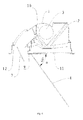
- an indoor unit of an air conditioner includes a casing 1, a heat exchanger 2, a fan 3 and a panel 4.
- the casing 1 defines a receiving cavity 10 therein, and the receiving cavity 10 has an air inlet 11 and an air outlet 12 formed in the bottom of the receiving cavity 10 and spaced apart from each other.
- the heat exchanger 2 is disposed in the receiving cavity 10 and adjacent to the air inlet 11 so as to perform heat exchanging with air low entering the receiving cavity 10 via the air inlet 11.
- the fan 3 is disposed in the receiving cavity 10 and brings air flow to the receiving cavity 10 via the air inlet 11, and the air flow through the heat exchanger 2 and the fan 3 is blown out via the air outlet 12.
- the panel 4 is disposed on the bottom of the casing 1, and the panel 4 is movable between a close position in which both the air inlet 11 and the air outlet 12 are closed by the panel 4 and an open position in which both the air inlet 11 and the air outlet 12 are open. In the open position, the panel at least partially separates the air entering via the air inlet 11 from the air exiting via the air outlet 12.
- the panel 4 when the indoor unit of the air conditioner is not operating, the panel 4 is in the close position and both the air inlet 11 and the air outlet 12 are closed by the panel 4, thus providing the indoor unit an aesthetic appearance and preventing dusts from entering into the receiving cavity.
- the panel 4 moves to the open position and the air inlet 11 and the air outlet 12 are separated from each other at least by the panel 4.
- the air blown out via the air outlet 12 may not be easily drawn into the receiving cavity 10 via the air inlet 11, thus avoiding a mixing of the blown air and the intake air.
- the indoor unit of the air conditioner by using the panel moveable between the close position and the open position, the air inlet and the air outlet are closed when the indoor unit is not operating, thus providing the indoor unit an aesthetic appearance and preventing dusts from entering into the interior of the indoor unit.
- the indoor unit when the indoor unit is operating, it may prevent cooled air or heated air blown out via the air outlet from returning into the indoor unit and mixing with the intake air, thus avoiding a loss of the cooling capacity or heating capacity and providing a better air blowing effect.
- the indoor unit of the air conditioner is described by an example in which the casing defines one receiving cavity therein.
- the casing defines two symmetry receiving cavities therein, and has two heat exchangers, two fans and at least two panels therein.
- an air inlet and an air outlet spaced apart from the air inlet are formed at the bottom of every receiving cavity.
- the two heat exchangers are disposed in the two receiving cavities respectively, the two fans are disposed in the two receiving cavities respectively, the at least two panels are disposed symmetrically on the bottom of the casing, and each panel is moveable between the close position in which one corresponding air inlet and one corresponding air outlet are both closed and the open position in which the one corresponding air inlet and the one corresponding air outlet are both open.
- the receiving cavity 10 defines one air outlet 12, the indoor unit includes one panel 4.
- the panel 4 can translate towards the air inlet 11 side from the close position to a spacing position, and rotate to the open position. When the panel 4 is in the spacing position, an end of the panel 4 abuts against a lower surface of a spacing portion 9 between the air inlet 11 and the air outlet 12, as shown in Figs. 1-2 and 6-10 .
- the indoor unit may include two or more air outlets and two or more corresponding panels.
- the receiving cavity 10 defines a plurality of air outlets disposed at at least two ends of the bottom of the casing 1
- the indoor unit includes a plurality of panels each disposed on the bottom of the casing and between one corresponding air inlet and one corresponding air outlet (not shown in the drawings). When the panels 4 are in close positions, the air inlet and air outlets are closed; when the panels are in open positions, the air inlet and the air outlets are open.
- the receiving cavity defines one air inlet and one air outlet and the indoor unit includes one corresponding panel.
- the movement includes a translation from the close position to the spacing position and a rotation from the spacing position to the open position.
- the panel 4 moves towards the air inlet 11 side from the close position (as shown in Fig. 1 ) to the spacing position (not shown in drawings), and then rotates to the open position.
- an end of the panel 4 is positioned below the spacing portion 9 between the air inlet 11 and the air outlet 12.
- a first end of the panel 4 abuts against the spacing portion 9 between the air inlet 11 and the air outlet 12, and a second end of the panel 4 is inclined downwards, and an angle ⁇ between a plane in which the panel 4 lies and a horizontal plane in which a lower surface of the casing 1 lies ranges from 15° to 150°.
- the panel 4 moves along a direction from the air outlet 12 to the air inlet 11, after moving to the spacing position, i.e. an end of the panel 4 abuts against the lower surface of the spacing portion 9, the other end of the panel 4 distant from the spacing portion 9 rotates away from the air inlet 11.
- the air inlet 11 is at the right side of the bottom of the casing 1, while the air outlet 12 is at the left side of the bottom of the casing 1.
- the movement of the panel 4 includes a translation from left to right, and a rotation in which the left end of the panel abuts against the bottom of the spacing portion 9 and the right end of the panel implements a clockwise rotation.
- the temperature of the air in the air inlet 11 may not be changed due to a far distance between the blown air and the air inlet 11 and a mixing between the blown air and the environmental air. In this way, the air blowing effect may not be influenced. Further, it prevents the cooled air or heated air newly blown out from being drawn back by adjacent air inlet(s) 11, thus preventing the cooled air or heated air from mixing with the intake air, and thus avoiding a loss the cooling capacity or the heating capacity.
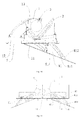
- axis X represents a horizontal direction
- axis Y represents a vertical direction
- these two axes are joint at coordinate origin O
- lines OA, OB, and OC represents position directions of three panels 4 respectively
- the coordinate origin O represents the intersection between the panel 4 and the lower surface of the spacing portion 9.
- the angle ⁇ may be 140°, such that substantially all cooled air may be blown out to the distant area at the air outlet 12 side. In this way, the air blowing speed is high and the air blowing distance is large, which provides a better cooling effect.
- the cooled air may not be blown to other areas, thus improving the utilization of the air conditioner.
- the angle ⁇ between the plane in which the panel 4 in the open position lies and the horizontal plane in which the lower surface of the casing 1 lies ranges from 40° to 140°.
- the angle ⁇ between the plane in which the panel 4 in the open position lies and the horizontal plane in which the lower surface of the casing 1 lies ranges from 15° to 75°.
- the panel 4 is swayable within the range defined by the angle ⁇ .
- the panel 4 acts as an air guiding component, and the angle ⁇ between the panel 4 and the horizontal plane in which the lower surface of the casing 1 lies is adjustable.
- the panel 4 can sway in the range defined by the angle ⁇ so as to adjust the air blowing angle and the air blowing range.
- the present disclosure is not limited to this embodiment.
- the panel 4 when the panel 4 is in the open position, the panel 4 is held in a position at which the angle ⁇ has a predetermined value. In other words, when the indoor unit of the air conditioner is operating, the panel 2 is held with a predetermined angle between the panel 4 and the lower surface of the casing 4, and the predetermined angle is maintained.
- the indoor unit of the air conditioner according to a further embodiment of the present disclosure further includes an air guide 5.
- the air guide 5 is disposed swayably at the air outlet 12 and configured to guide the air exiting via the air outlet 12. When the panel 4 is in the open position, the air guide 5 cooperates with the panel 4 so as to guide blown air to a larger area.
- the indoor unit of the air conditioner further includes a driving device.
- the driving device is disposed between the panel 4 and the casing 1 so as to drive the panel 4 to move between the close position and the open position.
- the driving device and the indoor unit of the air conditioner may be described below in detail in several embodiments with reference to Figs. 1-11 .
- the air inlet 11 is at the right side of the bottom of the casing 1
- the air outlet 12 is at the left side of the bottom of the casing 1 in these embodiments.
- a casing 1 defines a receiving cavity 10 therein.
- An air inlet 11 and an air outlet 12 spaced apart from the air inlet 11 are formed in the bottom of the receiving cavity 10, and a spacing portion 9 is formed between the air inlet 11 and the air outlet 12.
- a heat exchanger 2 and a fan 3 are disposed in the receiving cavity 10.
- a panel 4 is disposed on the bottom of the casing 1 and movable between a close position and an open position.
- the panel 4 when the panel 4 is in the open position, the panel 4 is held in a position at which an angle ⁇ has a predetermined value. Specifically, the left end of the panel 4 abuts against the spacing portion 9 between the air outlet 12 and the air inlet 11, and the right end of the panel 4 is inclined downwards and forms a specific angle with respect to the lower surface of the bottom of the casing 1, in which the angle ⁇ between the plane in which the panel 4 lies and the horizontal plane in which the lower surface of the casing 1 lies ranges from 15° to 150°.
- the angle ⁇ ranges from 15° to 150°. In the embodiment shown in Fig. 2 , the angle ⁇ is 60°.
- the driving device includes a first driving assembly 6 and a second driving assembly 7.
- the first driving assembly 6 is disposed between the panel 4 and the casing 1 so as to drive the panel 4 to translate to a predetermined position, i.e. the spacing position.
- the second driving assembly 7 is disposed between the panel 4 and the casing 1 so as to drive the panel 4 to make a clockwise rotation.
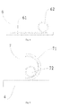
- the first driving assembly includes a first rack 61 and a first gear 62, the first rack 61 is disposed on the panel 4, the first gear 62 is disposed on the casing 1, and the panel 4 may translate with respect to the casing 1 under the meshing between the first rack 61 and the first gear 62.
- the first driving assembly includes a driving belt pulley and a belt (not shown in the drawings), the driving belt pulley is disposed on the casing 1, and the belt cooperates with the driving belt pulley so as to drive the panel 4 to translate with respect to the casing 1.
- the second driving assembly includes an arc rack 71 and a second gear 72, the arc rack 71 is disposed on the panel 4, the second gear 72 is disposed on the casing 1, the second gear 72 meshes with the arc rack 71 so as to drive the panel 4 to rotate with respect to the casing 1, as shown in Fig. 5 .
- the second driving assembly includes a driving gear and a gear train (not shown in the drawings), the driving gear is disposed on the casing 1, the gear train is disposed on the panel 4, and the gear train meshes with the driving gear so as to drive the panel 4 to rotate with respect to the casing 1.
- first driving assembly and the second driving assembly in the examples mentioned above may be combined independently of each other, which are not limited to combinations in embodiments shown in the drawings.
- the indoor unit of the air conditioner by using the first driving assembly and the second driving assembly, the translation and rotation of the panel may be implemented efficiently and rapidly, and the indoor unit has a simple structure.
- firstly the first driving assembly 6 drives the panel 4 to translate to the spacing position, and then the second driving assembly 7 drives the panel 4 to rotate to the open position and sway.
- the present disclosure is not limited to this embodiment.
- the first driving assembly 6 drives the panel 4 to translate at the same time as the second driving assembly 7 drives the panel 4 to rotate.
- the present Embodiment 2 has a structure substantially the same as that in Embodiment 1, in which same components are labeled with the same reference numerals, and with following differences.
- an air guide 5 is disposed at the air outlet 12, and the air guide 5 cooperates with the panel 4 so as to adjust the air blowing direction.
- the panel 4 can sway within the range defined by the angle ⁇ . Specifically, referring to Figs.
- the panel 4 when the panel 4 is in the open position, the left end of the panel 4 abuts against the spacing portion 9 between the air outlet 12 and the air inlet 11, the right end of the panel 4 inclines downwards and sways, and the angle ⁇ between the plane in which the panel 4 lies and the horizontal plane in which the lower surface of the casing 1 lies ranges from 15° to 150°.
- the panel 4 can sway continuously within the angle range of 15° to 150° so as to adjust the air blowing angle and the air blowing range continuously.
- the air guide 6 guides the air to the right side, and the panel 4 rotates to the right so as to make the angle ⁇ being 60°.
- the angle between the air guide 6 positioned to direct to the air blowing direction and the horizontal direction are identical or similar to the angle ⁇ between the panel 4 and the lower surface of the casing 1, thus facilitating to blow cooled air discharged via the air outlet 12 to the right side.
- the angle ⁇ between the panel 4 and the lower surface of the casing 1 is substantial 120°, and the air guide 6 guides the air to the left side and cooperates with the panel 4 so as to blow the cooled air discharged via the air outlet 12 to the left side.
- the angle ⁇ ranges from 40° to 140°. In this angle range, the cooperation between the air guide 6 and the panel 4 may realize blowing air to larger areas; meanwhile, the panel 4 prevents the blown air from diffusion, thus forming an air flow with a relatively higher flow rate along the panel 4. In this way, both the air blowing effect and flow guiding effect may be improved, and the blown air can be blown by a much further distance along the direction of the panel 4.
- the driving device for driving the panel 4 is similar to that in the above embodiment, thus details thereof are omitted herein.
- the present Embodiment 3 has a structure substantially the same as that in the Embodiment 2, in which the same components are labeled with the same reference numerals, and with the following differences.
- the panel 4 when the panel 4 is in the open position, the panel 4 is held in a position at which the angle ⁇ has a predetermined value.
- the angle ⁇ is 90°, i.e. the panel 4 guides the air blown out via the air outlet 12 to move vertically downwards.
- the air guide 5 disposed at air outlet 12 cooperates with the panel 4 so as to adjust the air blowing direction. As shown in Fig. 8 , the air guide 5 guide the air down, and the panel 4 is held in a position at which the angle ⁇ is 90°. As shown in Fig. 9 , the air guide 5 guides the air to the left side, and the panel 4 is held at the position at which the angle ⁇ is 90°.
- This embodiment is often used in the heating operation. Due to the need of blowing heated air to the bottom area of a room so as to improve a comfort provided by this room, it is more relied on the guide effect of the panel 4. When the angle ⁇ ranges from 75° to 120°, the heated air can be better delivered downwards. In this angle range, the panel 4 cooperates with the air guide 5, and thereby realizing blowing heated air to areas where users locate.
- the driving device for driving the panel 4 is similar to that in the above embodiment, thus details thereof are omitted herein.
- the present Embodiment 4 has a structure substantially the same as that in Embodiment 1, in which the same components are labeled with the same reference numerals, and with several differences in the structure of the driving device.
- the driving device includes a guide plate 81 and a slider 82, the guide plate 81 is connected to the panel 4 and has an arc sliding passage 811 therein, and the slider 82 is disposed on the casing and slidable in the arc sliding passage 811 so as to define a movement track of the guide plate 81 and drive the panel 4 to move between the close position and the open position.
- an outer gear rim 812 is formed at an outer edge of the guide plate 81
- the driving device further includes a driving gear 83
- the driving gear 83 is disposed on the casing 1 to mesh with the outer gear rim 812.
- the panel 4 is movable between the close position and the open position under the cooperation between the slider 82 and the arc sliding passage 811 and the cooperation between the driving gear 83 and the outer gear rim 812.
- the driving gear 83 drives the guide plate 81 to move downwards, and thereby driving the panel 4 to move downwards.
- the driving gear 83 rotates in reverse, such that the guide plate 81 moves back to the original position, such that the air inlet 11 and the air outlet 12 are closed by the panel 4.
- the driving device of the indoor unit is simple and useful, may provide reliable movements, and may drive the panel to a position at which the angle ⁇ has a predetermined value.
- the air conditioner is operating with small air volume.
- a flow rate of air at the air inlet and a flow rate of air at the air outlet are relatively lower.
- the angle ⁇ ranges from 75° to 15° in this mode. In such case, user requirements such as small air volume and low noises can be satisfied.
- Embodiment 5 differs from Embodiment 4 in that Embodiment 5 is an indoor unit including two indoor units of Embodiment 4 combined in mirror symmetry at the air outlet side.
- the casing defines two symmetry receiving cavities 10, and two heat exchangers 2, two fans 3 and two panels 4 are provided.
- an air inlet 11 and an air outlet 12 spaced apart from the air inlet 11 are disposed in the bottom of each receiving cavity 10
- the two heat exchangers 2 are disposed in the receiving cavities 10 respectively
- the two fans 3 are disposed in the receiving cavities 10 respectively
- the two panels 4 are disposed symmetrically on the bottom of the casing 1. Every panel 4 is movable between a close position in which one corresponding air inlet 11 and one corresponding air outlet 12 are both closed by the panel 4 and an open position in which the one corresponding air inlet 11 and the one corresponding air outlet 12 are both open.
- the panels 4 are driven by two driving devices described in Embodiment 4 respectively.
- two driving gears 83 drive corresponding guide plates 81 to move downwards respectively and the sliders 82 slide in corresponding arc sliding passages 811, so as to drive corresponding panels 4 to rotate to positions in which each of the angles ⁇ corresponding to the two panels has a predetermined value, and opposing ends of the two panels 4 abut against the spacing portion 9 between the air inlet 11 and the air outlet respectively.
- the indoor unit of the air conditioner is operating with small air volume.
- flow rates of air at the air inlet and at the air outlet are both relatively lower.
- the angle ⁇ ranges from 75° to 15° in this mode. In such case, requirements of users such as small air volume and low noise can be satisfied.
- the panel 4 may be held at the spacing portion 9 between the air outlet 12 and the air inlet 11, with the angle ⁇ having a predetermined value.
- the present disclosure provides following advantages: 1) with the panel closing the air inlet and the air outlet when the indoor unit is not operating, providing the indoor unit an aesthetic appearance and avoiding dusts from entering the interior of the indoor unit; 2) preventing the cooled air or heated air from returning to the indoor unit and mixing with the intake air, and avoiding a loss of the cooling capacity or the heating capacity; 3) realizing a better air blowing effect under the cooperation of the air guide; and 4) improving the speed of blowing air downwards and the static pressure in the heating operation.
Landscapes
- Engineering & Computer Science (AREA)
- Chemical & Material Sciences (AREA)
- Combustion & Propulsion (AREA)
- Mechanical Engineering (AREA)
- General Engineering & Computer Science (AREA)
- Physics & Mathematics (AREA)
- Thermal Sciences (AREA)
- Air Filters, Heat-Exchange Apparatuses, And Housings Of Air-Conditioning Units (AREA)
- Air-Flow Control Members (AREA)
Applications Claiming Priority (1)
| Application Number | Priority Date | Filing Date | Title |
|---|---|---|---|
| PCT/CN2012/080670 WO2014032229A1 (zh) | 2012-08-28 | 2012-08-28 | 空调室内机 |
Publications (3)
| Publication Number | Publication Date |
|---|---|
| EP2910862A1 true EP2910862A1 (de) | 2015-08-26 |
| EP2910862A4 EP2910862A4 (de) | 2016-07-27 |
| EP2910862B1 EP2910862B1 (de) | 2020-04-08 |
Family
ID=50182352
Family Applications (1)
| Application Number | Title | Priority Date | Filing Date |
|---|---|---|---|
| EP12883715.0A Active EP2910862B1 (de) | 2012-08-28 | 2012-08-28 | Klimaanlagen-innenraumeinheit |
Country Status (3)
| Country | Link |
|---|---|
| US (1) | US10254005B2 (de) |
| EP (1) | EP2910862B1 (de) |
| WO (1) | WO2014032229A1 (de) |
Cited By (3)
| Publication number | Priority date | Publication date | Assignee | Title |
|---|---|---|---|---|
| CN109974265A (zh) * | 2019-04-29 | 2019-07-05 | 广东美的制冷设备有限公司 | 用于风管机的回风组件和风管机 |
| CN114396656A (zh) * | 2022-01-10 | 2022-04-26 | 珠海格力节能环保制冷技术研究中心有限公司 | 风管机 |
| CN114396650A (zh) * | 2022-01-10 | 2022-04-26 | 珠海格力节能环保制冷技术研究中心有限公司 | 一种分布式送风风管机和分布式送风装置 |
Families Citing this family (16)
| Publication number | Priority date | Publication date | Assignee | Title |
|---|---|---|---|---|
| CN106338105B (zh) * | 2015-07-08 | 2020-04-10 | 松下知识产权经营株式会社 | 吸气装置以及吸气方法 |
| CN106287947B (zh) * | 2016-08-01 | 2022-03-01 | 奥克斯空调股份有限公司 | 一种壁挂式空调 |
| CN106440026B (zh) * | 2016-08-01 | 2022-05-13 | 奥克斯空调股份有限公司 | 一种壁挂式空调 |
| CN106885357A (zh) * | 2017-03-13 | 2017-06-23 | 奥克斯空调股份有限公司 | 一种空调器出风窗组件 |
| JP6855875B2 (ja) * | 2017-03-28 | 2021-04-07 | 株式会社富士通ゼネラル | 天井埋込型空気調和機の室内機 |
| KR102401527B1 (ko) * | 2017-09-28 | 2022-05-24 | 삼성전자주식회사 | 공기조화기 |
| CN107860063B (zh) * | 2017-11-02 | 2023-07-14 | 珠海格力节能环保制冷技术研究中心有限公司 | 室内机及具有其的空调器 |
| JP2019203630A (ja) * | 2018-05-22 | 2019-11-28 | 株式会社富士通ゼネラル | 天井埋込型空気調和機 |
| CN109974268B (zh) * | 2019-04-29 | 2024-07-19 | 广东美的制冷设备有限公司 | 用于风管机的回风组件和风管机 |
| CN111306761B (zh) * | 2020-03-27 | 2025-04-22 | 广东美的制冷设备有限公司 | 开关门组件及具有其的空调器 |
| JP2022057724A (ja) * | 2020-09-30 | 2022-04-11 | 株式会社富士通ゼネラル | 本体ユニットおよび空気調和機 |
| CN112682840A (zh) * | 2021-01-12 | 2021-04-20 | 佛山市得安电器科技有限公司 | 双层活动面板及顶棚取暖器 |
| CN112797481A (zh) * | 2021-02-02 | 2021-05-14 | 青岛海尔空调器有限总公司 | 空调室内机 |
| US12385666B2 (en) * | 2021-05-24 | 2025-08-12 | Lg Electronics Inc. | Air-processing apparatus |
| CN113959001A (zh) * | 2021-10-26 | 2022-01-21 | 珠海格力电器股份有限公司 | 室内机、空调器及空调器控制的方法 |
| CN115435402B (zh) * | 2022-09-26 | 2024-11-15 | 青岛海尔空调器有限总公司 | 空调器 |
Family Cites Families (15)
| Publication number | Priority date | Publication date | Assignee | Title |
|---|---|---|---|---|
| GB1147282A (en) * | 1966-06-20 | 1969-04-02 | Hitachi Ltd | Air conditioner |
| JPS5239315Y1 (de) * | 1970-12-31 | 1977-09-06 | ||
| JPS6110427U (ja) * | 1984-06-26 | 1986-01-22 | 木村工機株式会社 | 空気調和機 |
| JP2554769B2 (ja) | 1990-05-16 | 1996-11-13 | 株式会社東芝 | 液晶表示装置 |
| JPH0420923U (de) * | 1990-06-13 | 1992-02-21 | ||
| JP3614167B1 (ja) * | 2003-03-26 | 2005-01-26 | ダイキン工業株式会社 | 空気調和機の室内機 |
| JP4923639B2 (ja) * | 2005-11-11 | 2012-04-25 | ダイキン工業株式会社 | 空気調和装置の室内パネル及び空気調和装置 |
| JP4001172B1 (ja) * | 2006-04-17 | 2007-10-31 | ダイキン工業株式会社 | 空気調和装置 |
| JP4107334B2 (ja) * | 2006-04-21 | 2008-06-25 | ダイキン工業株式会社 | 空気調和装置 |
| JP4075936B2 (ja) * | 2006-04-21 | 2008-04-16 | ダイキン工業株式会社 | 空気調和装置 |
| JP4792348B2 (ja) * | 2006-07-31 | 2011-10-12 | 大成建設株式会社 | 吹出口の風向制御機構およびダクトレス換気システム |
| JP2009041851A (ja) * | 2007-08-09 | 2009-02-26 | Daikin Ind Ltd | 空気調和装置の室内機 |
| WO2009044830A1 (ja) * | 2007-10-02 | 2009-04-09 | Daikin Industries, Ltd. | 室内ユニット |
| JP4645755B2 (ja) * | 2009-07-13 | 2011-03-09 | ダイキン工業株式会社 | 空気調和機の室内機 |
| CN202835569U (zh) | 2012-08-28 | 2013-03-27 | 广东美的制冷设备有限公司 | 空调室内机 |
-
2012
- 2012-08-28 US US14/424,337 patent/US10254005B2/en not_active Expired - Fee Related
- 2012-08-28 EP EP12883715.0A patent/EP2910862B1/de active Active
- 2012-08-28 WO PCT/CN2012/080670 patent/WO2014032229A1/zh not_active Ceased
Cited By (3)
| Publication number | Priority date | Publication date | Assignee | Title |
|---|---|---|---|---|
| CN109974265A (zh) * | 2019-04-29 | 2019-07-05 | 广东美的制冷设备有限公司 | 用于风管机的回风组件和风管机 |
| CN114396656A (zh) * | 2022-01-10 | 2022-04-26 | 珠海格力节能环保制冷技术研究中心有限公司 | 风管机 |
| CN114396650A (zh) * | 2022-01-10 | 2022-04-26 | 珠海格力节能环保制冷技术研究中心有限公司 | 一种分布式送风风管机和分布式送风装置 |
Also Published As
| Publication number | Publication date |
|---|---|
| EP2910862B1 (de) | 2020-04-08 |
| US20150219359A1 (en) | 2015-08-06 |
| WO2014032229A1 (zh) | 2014-03-06 |
| EP2910862A4 (de) | 2016-07-27 |
| US10254005B2 (en) | 2019-04-09 |
Similar Documents
| Publication | Publication Date | Title |
|---|---|---|
| EP2910862B1 (de) | Klimaanlagen-innenraumeinheit | |
| CN106287938B (zh) | 空调器 | |
| CN209325925U (zh) | 空调室内机和具有其的空调器 | |
| CN103629744B (zh) | 空调室内机 | |
| WO2016197747A1 (zh) | 空调器 | |
| CN108180548B (zh) | 壁挂式空调室内机 | |
| KR102393966B1 (ko) | 공기조화기 | |
| CN113739272B (zh) | 导风部件、出风组件及空调器 | |
| CN209325921U (zh) | 空调室内机和具有其的空调器 | |
| KR20220060521A (ko) | 공기조화기 | |
| CN106287936A (zh) | 空调器及空调器的控制方法 | |
| CN107965845B (zh) | 室内机及应用其的空调器 | |
| CN114251730B (zh) | 风道组件和空调器 | |
| CN105318434B (zh) | 空调室内机 | |
| CN107477694B (zh) | 一种可上下送风的柜式空调器 | |
| WO2022252735A1 (zh) | 空调室内机 | |
| CN107726586B (zh) | 空调器及其控制方法 | |
| CN108592194A (zh) | 空调器 | |
| CN205641212U (zh) | 空调天花机 | |
| CN105157116A (zh) | 风管机 | |
| CN107606704B (zh) | 一种柜式空调器 | |
| CN105605736A (zh) | 空调送风方法 | |
| CN209689028U (zh) | 空调室内机和具有其的空调器 | |
| CN217464839U (zh) | 空调器 | |
| CN107166509B (zh) | 空调室内机 |
Legal Events
| Date | Code | Title | Description |
|---|---|---|---|
| PUAI | Public reference made under article 153(3) epc to a published international application that has entered the european phase |
Free format text: ORIGINAL CODE: 0009012 |
|
| 17P | Request for examination filed |
Effective date: 20150312 |
|
| AK | Designated contracting states |
Kind code of ref document: A1 Designated state(s): AL AT BE BG CH CY CZ DE DK EE ES FI FR GB GR HR HU IE IS IT LI LT LU LV MC MK MT NL NO PL PT RO RS SE SI SK SM TR |
|
| AX | Request for extension of the european patent |
Extension state: BA ME |
|
| DAX | Request for extension of the european patent (deleted) | ||
| RA4 | Supplementary search report drawn up and despatched (corrected) |
Effective date: 20160629 |
|
| RIC1 | Information provided on ipc code assigned before grant |
Ipc: F24F 13/20 20060101ALI20160623BHEP Ipc: F24F 13/14 20060101ALI20160623BHEP Ipc: F24F 13/12 20060101ALI20160623BHEP Ipc: F24F 1/00 20110101AFI20160623BHEP |
|
| GRAP | Despatch of communication of intention to grant a patent |
Free format text: ORIGINAL CODE: EPIDOSNIGR1 |
|
| STAA | Information on the status of an ep patent application or granted ep patent |
Free format text: STATUS: GRANT OF PATENT IS INTENDED |
|
| RIC1 | Information provided on ipc code assigned before grant |
Ipc: F24F 13/20 20060101ALI20191004BHEP Ipc: F24F 13/14 20060101ALI20191004BHEP Ipc: F24F 1/0047 20190101ALI20191004BHEP Ipc: F24F 1/00 20190101AFI20191004BHEP Ipc: F24F 13/12 20060101ALI20191004BHEP Ipc: F24F 1/0011 20190101ALI20191004BHEP |
|
| INTG | Intention to grant announced |
Effective date: 20191028 |
|
| GRAS | Grant fee paid |
Free format text: ORIGINAL CODE: EPIDOSNIGR3 |
|
| GRAA | (expected) grant |
Free format text: ORIGINAL CODE: 0009210 |
|
| STAA | Information on the status of an ep patent application or granted ep patent |
Free format text: STATUS: THE PATENT HAS BEEN GRANTED |
|
| AK | Designated contracting states |
Kind code of ref document: B1 Designated state(s): AL AT BE BG CH CY CZ DE DK EE ES FI FR GB GR HR HU IE IS IT LI LT LU LV MC MK MT NL NO PL PT RO RS SE SI SK SM TR |
|
| RAP1 | Party data changed (applicant data changed or rights of an application transferred) |
Owner name: GD MIDEA AIR-CONDITIONING EQUIPMENT CO., LTD. |
|
| REG | Reference to a national code |
Ref country code: AT Ref legal event code: REF Ref document number: 1254904 Country of ref document: AT Kind code of ref document: T Effective date: 20200415 Ref country code: CH Ref legal event code: EP |
|
| REG | Reference to a national code |
Ref country code: IE Ref legal event code: FG4D |
|
| REG | Reference to a national code |
Ref country code: DE Ref legal event code: R096 Ref document number: 602012069217 Country of ref document: DE |
|
| REG | Reference to a national code |
Ref country code: NL Ref legal event code: MP Effective date: 20200408 |
|
| REG | Reference to a national code |
Ref country code: LT Ref legal event code: MG4D |
|
| PG25 | Lapsed in a contracting state [announced via postgrant information from national office to epo] |
Ref country code: SE Free format text: LAPSE BECAUSE OF FAILURE TO SUBMIT A TRANSLATION OF THE DESCRIPTION OR TO PAY THE FEE WITHIN THE PRESCRIBED TIME-LIMIT Effective date: 20200408 Ref country code: NO Free format text: LAPSE BECAUSE OF FAILURE TO SUBMIT A TRANSLATION OF THE DESCRIPTION OR TO PAY THE FEE WITHIN THE PRESCRIBED TIME-LIMIT Effective date: 20200708 Ref country code: IS Free format text: LAPSE BECAUSE OF FAILURE TO SUBMIT A TRANSLATION OF THE DESCRIPTION OR TO PAY THE FEE WITHIN THE PRESCRIBED TIME-LIMIT Effective date: 20200808 Ref country code: GR Free format text: LAPSE BECAUSE OF FAILURE TO SUBMIT A TRANSLATION OF THE DESCRIPTION OR TO PAY THE FEE WITHIN THE PRESCRIBED TIME-LIMIT Effective date: 20200709 Ref country code: FI Free format text: LAPSE BECAUSE OF FAILURE TO SUBMIT A TRANSLATION OF THE DESCRIPTION OR TO PAY THE FEE WITHIN THE PRESCRIBED TIME-LIMIT Effective date: 20200408 Ref country code: PT Free format text: LAPSE BECAUSE OF FAILURE TO SUBMIT A TRANSLATION OF THE DESCRIPTION OR TO PAY THE FEE WITHIN THE PRESCRIBED TIME-LIMIT Effective date: 20200817 Ref country code: NL Free format text: LAPSE BECAUSE OF FAILURE TO SUBMIT A TRANSLATION OF THE DESCRIPTION OR TO PAY THE FEE WITHIN THE PRESCRIBED TIME-LIMIT Effective date: 20200408 Ref country code: LT Free format text: LAPSE BECAUSE OF FAILURE TO SUBMIT A TRANSLATION OF THE DESCRIPTION OR TO PAY THE FEE WITHIN THE PRESCRIBED TIME-LIMIT Effective date: 20200408 |
|
| REG | Reference to a national code |
Ref country code: AT Ref legal event code: MK05 Ref document number: 1254904 Country of ref document: AT Kind code of ref document: T Effective date: 20200408 |
|
| PG25 | Lapsed in a contracting state [announced via postgrant information from national office to epo] |
Ref country code: LV Free format text: LAPSE BECAUSE OF FAILURE TO SUBMIT A TRANSLATION OF THE DESCRIPTION OR TO PAY THE FEE WITHIN THE PRESCRIBED TIME-LIMIT Effective date: 20200408 Ref country code: BG Free format text: LAPSE BECAUSE OF FAILURE TO SUBMIT A TRANSLATION OF THE DESCRIPTION OR TO PAY THE FEE WITHIN THE PRESCRIBED TIME-LIMIT Effective date: 20200708 Ref country code: RS Free format text: LAPSE BECAUSE OF FAILURE TO SUBMIT A TRANSLATION OF THE DESCRIPTION OR TO PAY THE FEE WITHIN THE PRESCRIBED TIME-LIMIT Effective date: 20200408 Ref country code: HR Free format text: LAPSE BECAUSE OF FAILURE TO SUBMIT A TRANSLATION OF THE DESCRIPTION OR TO PAY THE FEE WITHIN THE PRESCRIBED TIME-LIMIT Effective date: 20200408 |
|
| PG25 | Lapsed in a contracting state [announced via postgrant information from national office to epo] |
Ref country code: AL Free format text: LAPSE BECAUSE OF FAILURE TO SUBMIT A TRANSLATION OF THE DESCRIPTION OR TO PAY THE FEE WITHIN THE PRESCRIBED TIME-LIMIT Effective date: 20200408 |
|
| REG | Reference to a national code |
Ref country code: DE Ref legal event code: R097 Ref document number: 602012069217 Country of ref document: DE |
|
| PG25 | Lapsed in a contracting state [announced via postgrant information from national office to epo] |
Ref country code: EE Free format text: LAPSE BECAUSE OF FAILURE TO SUBMIT A TRANSLATION OF THE DESCRIPTION OR TO PAY THE FEE WITHIN THE PRESCRIBED TIME-LIMIT Effective date: 20200408 Ref country code: SM Free format text: LAPSE BECAUSE OF FAILURE TO SUBMIT A TRANSLATION OF THE DESCRIPTION OR TO PAY THE FEE WITHIN THE PRESCRIBED TIME-LIMIT Effective date: 20200408 Ref country code: AT Free format text: LAPSE BECAUSE OF FAILURE TO SUBMIT A TRANSLATION OF THE DESCRIPTION OR TO PAY THE FEE WITHIN THE PRESCRIBED TIME-LIMIT Effective date: 20200408 Ref country code: DK Free format text: LAPSE BECAUSE OF FAILURE TO SUBMIT A TRANSLATION OF THE DESCRIPTION OR TO PAY THE FEE WITHIN THE PRESCRIBED TIME-LIMIT Effective date: 20200408 Ref country code: CZ Free format text: LAPSE BECAUSE OF FAILURE TO SUBMIT A TRANSLATION OF THE DESCRIPTION OR TO PAY THE FEE WITHIN THE PRESCRIBED TIME-LIMIT Effective date: 20200408 Ref country code: RO Free format text: LAPSE BECAUSE OF FAILURE TO SUBMIT A TRANSLATION OF THE DESCRIPTION OR TO PAY THE FEE WITHIN THE PRESCRIBED TIME-LIMIT Effective date: 20200408 Ref country code: ES Free format text: LAPSE BECAUSE OF FAILURE TO SUBMIT A TRANSLATION OF THE DESCRIPTION OR TO PAY THE FEE WITHIN THE PRESCRIBED TIME-LIMIT Effective date: 20200408 Ref country code: IT Free format text: LAPSE BECAUSE OF FAILURE TO SUBMIT A TRANSLATION OF THE DESCRIPTION OR TO PAY THE FEE WITHIN THE PRESCRIBED TIME-LIMIT Effective date: 20200408 |
|
| PLBE | No opposition filed within time limit |
Free format text: ORIGINAL CODE: 0009261 |
|
| STAA | Information on the status of an ep patent application or granted ep patent |
Free format text: STATUS: NO OPPOSITION FILED WITHIN TIME LIMIT |
|
| PG25 | Lapsed in a contracting state [announced via postgrant information from national office to epo] |
Ref country code: PL Free format text: LAPSE BECAUSE OF FAILURE TO SUBMIT A TRANSLATION OF THE DESCRIPTION OR TO PAY THE FEE WITHIN THE PRESCRIBED TIME-LIMIT Effective date: 20200408 Ref country code: SK Free format text: LAPSE BECAUSE OF FAILURE TO SUBMIT A TRANSLATION OF THE DESCRIPTION OR TO PAY THE FEE WITHIN THE PRESCRIBED TIME-LIMIT Effective date: 20200408 |
|
| 26N | No opposition filed |
Effective date: 20210112 |
|
| PG25 | Lapsed in a contracting state [announced via postgrant information from national office to epo] |
Ref country code: MC Free format text: LAPSE BECAUSE OF FAILURE TO SUBMIT A TRANSLATION OF THE DESCRIPTION OR TO PAY THE FEE WITHIN THE PRESCRIBED TIME-LIMIT Effective date: 20200408 |
|
| REG | Reference to a national code |
Ref country code: CH Ref legal event code: PL |
|
| PG25 | Lapsed in a contracting state [announced via postgrant information from national office to epo] |
Ref country code: LU Free format text: LAPSE BECAUSE OF NON-PAYMENT OF DUE FEES Effective date: 20200828 Ref country code: LI Free format text: LAPSE BECAUSE OF NON-PAYMENT OF DUE FEES Effective date: 20200831 Ref country code: CH Free format text: LAPSE BECAUSE OF NON-PAYMENT OF DUE FEES Effective date: 20200831 |
|
| REG | Reference to a national code |
Ref country code: BE Ref legal event code: MM Effective date: 20200831 |
|
| PG25 | Lapsed in a contracting state [announced via postgrant information from national office to epo] |
Ref country code: SI Free format text: LAPSE BECAUSE OF FAILURE TO SUBMIT A TRANSLATION OF THE DESCRIPTION OR TO PAY THE FEE WITHIN THE PRESCRIBED TIME-LIMIT Effective date: 20200408 |
|
| PG25 | Lapsed in a contracting state [announced via postgrant information from national office to epo] |
Ref country code: IE Free format text: LAPSE BECAUSE OF NON-PAYMENT OF DUE FEES Effective date: 20200828 Ref country code: BE Free format text: LAPSE BECAUSE OF NON-PAYMENT OF DUE FEES Effective date: 20200831 |
|
| PGFP | Annual fee paid to national office [announced via postgrant information from national office to epo] |
Ref country code: FR Payment date: 20210715 Year of fee payment: 10 |
|
| PGFP | Annual fee paid to national office [announced via postgrant information from national office to epo] |
Ref country code: GB Payment date: 20210722 Year of fee payment: 10 |
|
| PG25 | Lapsed in a contracting state [announced via postgrant information from national office to epo] |
Ref country code: TR Free format text: LAPSE BECAUSE OF FAILURE TO SUBMIT A TRANSLATION OF THE DESCRIPTION OR TO PAY THE FEE WITHIN THE PRESCRIBED TIME-LIMIT Effective date: 20200408 Ref country code: MT Free format text: LAPSE BECAUSE OF FAILURE TO SUBMIT A TRANSLATION OF THE DESCRIPTION OR TO PAY THE FEE WITHIN THE PRESCRIBED TIME-LIMIT Effective date: 20200408 Ref country code: CY Free format text: LAPSE BECAUSE OF FAILURE TO SUBMIT A TRANSLATION OF THE DESCRIPTION OR TO PAY THE FEE WITHIN THE PRESCRIBED TIME-LIMIT Effective date: 20200408 |
|
| PG25 | Lapsed in a contracting state [announced via postgrant information from national office to epo] |
Ref country code: MK Free format text: LAPSE BECAUSE OF FAILURE TO SUBMIT A TRANSLATION OF THE DESCRIPTION OR TO PAY THE FEE WITHIN THE PRESCRIBED TIME-LIMIT Effective date: 20200408 |
|
| PGFP | Annual fee paid to national office [announced via postgrant information from national office to epo] |
Ref country code: DE Payment date: 20220608 Year of fee payment: 11 |
|
| GBPC | Gb: european patent ceased through non-payment of renewal fee |
Effective date: 20220828 |
|
| PG25 | Lapsed in a contracting state [announced via postgrant information from national office to epo] |
Ref country code: FR Free format text: LAPSE BECAUSE OF NON-PAYMENT OF DUE FEES Effective date: 20220831 |
|
| PG25 | Lapsed in a contracting state [announced via postgrant information from national office to epo] |
Ref country code: GB Free format text: LAPSE BECAUSE OF NON-PAYMENT OF DUE FEES Effective date: 20220828 |
|
| REG | Reference to a national code |
Ref country code: DE Ref legal event code: R119 Ref document number: 602012069217 Country of ref document: DE |
|
| PG25 | Lapsed in a contracting state [announced via postgrant information from national office to epo] |
Ref country code: DE Free format text: LAPSE BECAUSE OF NON-PAYMENT OF DUE FEES Effective date: 20240301 |