EP2910896B1 - Verfahren zur messung der lage einer antenne - Google Patents
Verfahren zur messung der lage einer antenne Download PDFInfo
- Publication number
- EP2910896B1 EP2910896B1 EP13847867.2A EP13847867A EP2910896B1 EP 2910896 B1 EP2910896 B1 EP 2910896B1 EP 13847867 A EP13847867 A EP 13847867A EP 2910896 B1 EP2910896 B1 EP 2910896B1
- Authority
- EP
- European Patent Office
- Prior art keywords
- antenna
- sensor
- angle
- attitude measurement
- module
- Prior art date
- Legal status (The legal status is an assumption and is not a legal conclusion. Google has not performed a legal analysis and makes no representation as to the accuracy of the status listed.)
- Active
Links
Images
Classifications
-
- G—PHYSICS
- G01—MEASURING; TESTING
- G01B—MEASURING LENGTH, THICKNESS OR SIMILAR LINEAR DIMENSIONS; MEASURING ANGLES; MEASURING AREAS; MEASURING IRREGULARITIES OF SURFACES OR CONTOURS
- G01B21/00—Measuring arrangements or details thereof, where the measuring technique is not covered by the other groups of this subclass, unspecified or not relevant
- G01B21/22—Measuring arrangements or details thereof, where the measuring technique is not covered by the other groups of this subclass, unspecified or not relevant for measuring angles or tapers; for testing the alignment of axes
-
- G—PHYSICS
- G01—MEASURING; TESTING
- G01C—MEASURING DISTANCES, LEVELS OR BEARINGS; SURVEYING; NAVIGATION; GYROSCOPIC INSTRUMENTS; PHOTOGRAMMETRY OR VIDEOGRAMMETRY
- G01C17/00—Compasses; Devices for ascertaining true or magnetic north for navigation or surveying purposes
- G01C17/34—Sun- or astro-compasses
-
- G—PHYSICS
- G01—MEASURING; TESTING
- G01C—MEASURING DISTANCES, LEVELS OR BEARINGS; SURVEYING; NAVIGATION; GYROSCOPIC INSTRUMENTS; PHOTOGRAMMETRY OR VIDEOGRAMMETRY
- G01C21/00—Navigation; Navigational instruments not provided for in groups G01C1/00 - G01C19/00
- G01C21/02—Navigation; Navigational instruments not provided for in groups G01C1/00 - G01C19/00 by astronomical means
- G01C21/025—Navigation; Navigational instruments not provided for in groups G01C1/00 - G01C19/00 by astronomical means with the use of startrackers
-
- G—PHYSICS
- G01—MEASURING; TESTING
- G01P—MEASURING LINEAR OR ANGULAR SPEED, ACCELERATION, DECELERATION, OR SHOCK; INDICATING PRESENCE, ABSENCE, OR DIRECTION, OF MOVEMENT
- G01P15/00—Measuring acceleration; Measuring deceleration; Measuring shock, i.e. sudden change of acceleration
-
- G—PHYSICS
- G01—MEASURING; TESTING
- G01S—RADIO DIRECTION-FINDING; RADIO NAVIGATION; DETERMINING DISTANCE OR VELOCITY BY USE OF RADIO WAVES; LOCATING OR PRESENCE-DETECTING BY USE OF THE REFLECTION OR RERADIATION OF RADIO WAVES; ANALOGOUS ARRANGEMENTS USING OTHER WAVES
- G01S19/00—Satellite radio beacon positioning systems; Determining position, velocity or attitude using signals transmitted by such systems
- G01S19/38—Determining a navigation solution using signals transmitted by a satellite radio beacon positioning system
- G01S19/39—Determining a navigation solution using signals transmitted by a satellite radio beacon positioning system the satellite radio beacon positioning system transmitting time-stamped messages, e.g. GPS [Global Positioning System], GLONASS [Global Orbiting Navigation Satellite System] or GALILEO
- G01S19/53—Determining attitude
Definitions
- the present invention relates to the technical field of communication, in particular to a sensor for detecting an antenna attitude in a communication network and an antenna attitude detection method.
- project parameter data of a base station antenna is the most basic element
- the measurement of the project parameter data is the most basic work in production operation such as construction, maintenance and optimization of the communication base station antenna
- high efficiency and accuracy of the communication network quality can be ensured only by carrying out work such as network planning and optimization on the basis of integrated and reliable project parameter data of the antenna.
- the project parameter of the antenna mainly includes an azimuth angle, a pitch angle, a roll angle, a height, a physical position and the like.
- the azimuth angle is usually increased clockwise by taking the true north as 0 degree and taking the true south as 180 degrees.
- the azimuth angle of the antenna is determined by a position of the antenna, and an accurate azimuth angle can ensure that an actual coverage of a base station is as expected and further ensure operation quality of the network.
- the azimuth angle of the antenna can be properly adjusted so as to better optimize a conventional communication network according to traffic or a specific condition of the network.
- the pitch angle includes a depression angle (i.e. downward inclination angle) and an elevation angle (i.e.
- the pitch angle of an antenna usually refers to a downward inclination angle of the antenna.
- the selection of a proper pitch angle may minimize energy superposition between electromagnetic wave existing between the antenna and a coverage boundary of the antenna and electromagnetic wave existing in the coverage of another antenna, thereby minimizing signal interference between neighbour areas.
- An excessively small pitch angle may lead to signal cross coverage between the neighbour areas, neighbour switching relation clutter and serious signal interference in a system. While an excessively large pitch angle may cause formation of a blind or weak signal area in the coverage, and simultaneously cause deformation in a shape of an antenna pattern to result in serious intra-system interference.
- the roll angle is one of necessary parameters for describing a space attitude of an object.
- the roll angle of the antenna is not included in a conventional antenna project parameter under normal circumstances, which is caused by a limitation of a conventional testing means and inattention to its importance.
- the base station antenna When the base station antenna is mounted, it is substantially necessary to ensure that a longitudinal section passing through a centre of the antenna is perpendicular to the ground, and then the roll angle of the antenna is zero.
- a considerable proportion of roll angles of antennae have a great offset relative to zero.
- a relatively large non-zero roll angle may cause the great deviation of a radio wave range in the direction to be covered from an expected range, which results in the inaccuracy of related planning optimization.
- Antenna attitude measurement refers to the accurate measurement of the attitude project parameter data of the antenna for providing a reliable foundation for the construction of the network.
- Conventional antenna attitude measurement is implemented by the manual measurement of an engineer with multiple tools. Azimuth angles of most of angles are manually determined by virtue of a compass. A line of magnetic force of the earth is poorer in consistency, so that the compass is easily restricted by a natural condition, and thus cannot provide consistent direction measurement. Factors such as a magnetic declination of probably 0 to 20 degrees of a certain point on the earth, possible influence of a geomagnetic storm on a geomagnetic index and non-uniform distribution of minerals on the earth may cause a change in north pole. Generally, the consistency of a direction of a line of magnetic force within a range of only several kilometres can be ensured in an ordinary place on the earth.
- the pitch angle of the antenna is determined by a method of inspecting a low-accuracy scale mark made on an antenna mounting frame by the engineer, and different engineers may have different working skills and adopt different measurement methods, so that a greater error in a measurement result may be caused, and a requirement of accurate design cannot be met.
- the document EP 2 498 050 A2 discloses an attitude measurement sensor which is suitable for an antenna, comprising a sun position sensor, a Global Positioning System (GPS) module, a central processing unit and an output module, wherein the central processing unit is connected with the sun position sensor, the GPS module and the output module. Furthermore, the sensor can be refined by adding inclinometers for correcting the attitude output in cases where the sensor is not horizontal.
- GPS Global Positioning System
- the document US 2009/040106 A1 discloses an antenna comprising a peripheral unit having an attitude measurement sensor, wherein the sensor comprises: a sun position sensor, a Global Positioning System (GPS) module, inclinometers, a central processing unit, a power module and an output module, wherein the central processing unit and the power module are connected with the sun position sensor, the GPS module, the inclinometers and the output module.
- GPS Global Positioning System
- the document KR 2010 0010233 A discloses a method using an attitude measuring sensor mounted to an antenna, the sensor comprising a digital electromagnetic compass, a GPS receiver and a tilt sensor all linked to a CPU, wherein the method uses the sensors in cooperation with the CPU to determine azimuth, tilt angle and location of the antenna.
- the document JP 2012 088073 A discloses an attitude measurement sensor which would be suitable for an antenna, comprising a sun position sensor, a terrestrial radio-based positioning system and a timing module, a three-axis gravity acceleration sensor, a central processing unit, a storage module and an output module, wherein the central processing unit is connected with the sun position sensor, the acceleration sensor and the modules mentioned before.
- the technical problem to be solved by the present invention is to provide a sensor free from magnetic interference and capable of accurately measuring various project parameter data of an antenna and to provide an antenna attitude measurement method based on the antenna attitude measurement sensor.
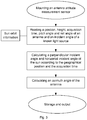
- An antenna attitude measurement method is provided, wherein the method is based on an antenna attitude measurement sensor, the antenna attitude measurement sensor comprising a shell, and a sun position sensor, a three-axis gravity acceleration sensor, a Global Positioning System (GPS) module, a central processing unit, a power module and a storage and output module, which are arranged in the shell, wherein an input end of the central processing unit is connected with output ends of the sun position sensor, the three-axis gravity acceleration sensor and the GPS module respectively, and an output end of the central processing unit is connected with the storage and output module, wherein the power module is connected with the sun position sensor, the three-axis gravity acceleration sensor, the GPS module, the central processing unit and the storage and output module respectively, and wherein a three-axis coordinate system of the sun position sensor forms a translation relationship with a three-axis coordinate system of the three-axis gravity acceleration sensor, the method comprising:
- the sunlight is combined with the other attitude measurement information of the antenna to realize the measurement of a direction of the antenna, so that orientation inaccuracy caused by magnetic interference during conventional magnetic orientation is avoided, the accuracy of the project parameter measurement data of the antenna is ensured, and a reliable foundation is provided for the construction, maintenance and optimization of the communication base station antenna.
- the sun position sensor, the three-axis gravity acceleration sensor and the GPS module in the antenna attitude measurement sensor work under the coordination of the central processing unit, and the central processing unit comprehensively analyzes and calculating the acquired information in combination with the sun orbit information by virtue of a timing function of the GPS module, thereby obtaining each project parameter of the antenna.
- Manual operation in measurement only includes the fixation of the attitude measurement sensor on the antenna with a space attitude the same as that of the antenna, so that the project parameters of the antenna can be measured by one piece of equipment and one operation, and working efficiency and accuracy are greatly improved.
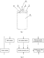
- An antenna attitude measurement sensor mainly includes a shell 2, and a sun position sensor 3, a three-axis gravity acceleration sensor 4, a GPS module 5, a central processing unit, a power module and a storage and output module, which are arranged in the shell, wherein an input end of the central processing unit is connected with output ends of the sun position sensor, the three-axis gravity acceleration sensor and the GPS module respectively, and an output end of the central processing unit is connected with the storage and output module; and the power module is connected with the sun position sensor, the three-axis gravity acceleration sensor, the GPS module, the central processing unit and the storage and output module respectively.
- a horizontal plane of the sun position sensor is parallel to a horizontal plane of the three-axis gravity acceleration sensor, and an initial 0-degree angle of the three-axis gravity acceleration sensor is consistent with a 0-degree angle of the sun position sensor, that is, a three-axis coordinate system of the sun position sensor forms a translation relationship with a three-axis coordinate system of the three-axis gravity acceleration sensor.
- the sun position sensor includes a dial surface, a style 6 and a style shadow angle sensor, and when the sun shines on a sundial at a certain moment in a certain day, a projection angle of the style on the dial surface can be determined by the style shadow angle sensor on the dial surface.
- the projection angle of the style on the dial surface is determined by taking a photo for image processing by a camera, thereby obtaining an incident azimuth angle ⁇ of the sun relative to the dial surface.
- An antenna attitude measurement method wherein the antenna attitude measurement method is based on an antenna attitude measurement sensor, and includes:
- the three-axis coordinate system of the antenna attitude measurement sensor may not be parallel to the three-axis coordinate system of the antenna, that is, a fixed offset angle can be kept (the offset angle is obtained after spatial rotation about an origin of the three-axis coordinate system), and the offset angle is eliminated (i.e. reverse rotation by the same angle) is eliminated from a final result to obtain a basic project parameter of the antenna.
- the direction of the antenna can be measured by adopting a manually arranged light source at a known position instead of the sun.
- the light source at the known position is used, if an angle cannot be formed above the sundial, the azimuth of the antenna can be measured by placing the light source at the known position below the sundial and inverting the sundial.
- the synchronous timing of the GPS module may not be required during the angle acquisition of the sun position sensor.
- the present invention can be applied to one-time project measurement, or can be placed on the antenna for the real-time monitoring of the attitude of the antenna for a long time.
- a clock module can be adopted instead of the GPS module, and only a synchronization function of the clock module is used for synchronously recording formation time of a specific angle on the sundial.
Landscapes
- Engineering & Computer Science (AREA)
- Radar, Positioning & Navigation (AREA)
- Remote Sensing (AREA)
- Physics & Mathematics (AREA)
- General Physics & Mathematics (AREA)
- Computer Networks & Wireless Communication (AREA)
- Astronomy & Astrophysics (AREA)
- Automation & Control Theory (AREA)
- Position Fixing By Use Of Radio Waves (AREA)
- Mobile Radio Communication Systems (AREA)
- Navigation (AREA)
Claims (1)
- Antennenlagemessverfahren, wobei das Verfahren auf einem Antennenlagemesssensor basiert, wobei der Antennenlagemesssensor ein Gehäuse (2) und einen Sonnenpositionssensor (3), einen Dreiachsen-Schwerkraft-Beschleunigungssensor (4), ein Global-Positioning-System(GPS)-Modul (5), eine zentrale Verarbeitungseinheit, ein Strommodul und ein Speicher- und Ausgabemodul, die in dem Gehäuse (2) angeordnet sind, umfasst, wobei ein Eingangsende der zentralen Verarbeitungseinheit mit Ausgangsenden jeweils des Sonnenpositionssensors (3), des Dreiachsen-Schwerkraft-Beschleunigungssensors (4) und des GPS-Moduls (5) verbunden ist und ein Ausgangsende der zentralen Verarbeitungseinheit mit dem Speicher- und Ausgabemodul verbunden ist, wobei das Strommodul jeweils mit dem Sonnenpositionssensor (3), dem Dreiachsen-Schwerkraft-Beschleunigungssensor (4), dem GPS-Modul (5), der zentralen Verarbeitungseinheit und dem Speicher- und Ausgabemodul verbunden ist und wobei ein Dreiachsen-Koordinatensystem des Sonnenpositionssensors (3) eine Translationsbeziehung mit einem Dreiachsen-Koordinatensystem des Dreiachsen-Schwerkraft-Beschleunigungssensors (4) ausbildet, wobei das Verfahren Folgendes umfasst:a. stabiles Montieren des Antennenlagemesssensors an einer gemessenen Antenne (1), damit ein Dreiachsen-Koordinatensystem des Antennenlagemesssensors zu einem Dreiachsen-Koordinatensystem der Antenne (1) parallel stehen kann;b. Erfassen, durch das GPS-Modul (5), einer geographischen Position und Höhe der Antenne (1) und von Normalzeit bei einem entsprechenden Azimutwinkel, Erhalten, durch den Dreiachsen-Schwerkraft-Beschleunigungssensor (4), eines Nickwinkels γ und eines Rollwinkels θ der Antenne (1) und Erfassen, durch den Sonnenpositionssensor (2), eines Azimutwinkels φ des einfallenden Sonnenlichts auf eine Referenzoberfläche der Antenne (1) relativ zu dem Sonnenpositionssensor (2);c. Ableiten eines vertikalen Einfallswinkels α und eines horizontalen Einfallswinkels β des Sonnenlichts relativ zu einer lokalen geographischen Referenzoberfläche in Kombination mit Sonnenumlaufinformationen gemäß der geographischen Position der Antenne (1) und der Normalzeit, die durch das GPS-Modul (5) in dem Antennenlagemesssensor erfasst werden;d. Berechnen eines Azimutwinkels δ der Antenne (1) gemäß Daten, die in Schritten b und c erhalten wurden, vermittels einer Formel wie folgt:
 e. Wiederholen der Schritte b bis d und Messen, Speichern und Ausgeben mehrerer Sätze von Antennenprojektparameterdatenoptimierungsergebnissen, wobei die Projektparameterdaten einen Azimutwinkel, einen Nickwinkel, einen Rollwinkel, eine Höhe und eine physische Position der Antenne (1) beinhalten.
Applications Claiming Priority (2)
| Application Number | Priority Date | Filing Date | Title |
|---|---|---|---|
| CN201210396600.5A CN102901484B (zh) | 2012-10-18 | 2012-10-18 | 天线测姿传感器以及天线测姿方法 |
| PCT/CN2013/084719 WO2014059881A1 (zh) | 2012-10-18 | 2013-09-30 | 天线测姿传感器以及天线测姿方法 |
Publications (3)
| Publication Number | Publication Date |
|---|---|
| EP2910896A1 EP2910896A1 (de) | 2015-08-26 |
| EP2910896A4 EP2910896A4 (de) | 2016-08-03 |
| EP2910896B1 true EP2910896B1 (de) | 2020-04-08 |
Family
ID=47573850
Family Applications (1)
| Application Number | Title | Priority Date | Filing Date |
|---|---|---|---|
| EP13847867.2A Active EP2910896B1 (de) | 2012-10-18 | 2013-09-30 | Verfahren zur messung der lage einer antenne |
Country Status (5)
| Country | Link |
|---|---|
| US (1) | US9945663B2 (de) |
| EP (1) | EP2910896B1 (de) |
| JP (1) | JP6455789B2 (de) |
| CN (1) | CN102901484B (de) |
| WO (1) | WO2014059881A1 (de) |
Families Citing this family (23)
| Publication number | Priority date | Publication date | Assignee | Title |
|---|---|---|---|---|
| CN102901484B (zh) * | 2012-10-18 | 2014-07-23 | 毕诗捷 | 天线测姿传感器以及天线测姿方法 |
| CN103471563B (zh) * | 2013-09-27 | 2015-05-20 | 重庆大学 | 分布式相控阵天线的子阵波束指向角度校正方法 |
| CN103983235B (zh) * | 2014-05-30 | 2016-05-18 | 西安融思电子信息技术有限公司 | 基站天线工程参数测量方法 |
| EP3183712B1 (de) * | 2014-08-18 | 2020-07-22 | Google LLC | Bestimmung der kompassausrichtung von bildern |
| CN104571144A (zh) * | 2014-12-05 | 2015-04-29 | 中国联合网络通信集团有限公司 | 远程控制单元rcu |
| WO2017008304A1 (zh) * | 2015-07-16 | 2017-01-19 | 华为技术有限公司 | 一种天线姿态的检测方法和装置 |
| CN106711607B (zh) * | 2015-07-31 | 2020-06-05 | 中国电信股份有限公司 | 一种天线方位角的远程测量方法、装置及网管系统 |
| CN106384889B (zh) * | 2015-07-31 | 2019-08-23 | 中国电信股份有限公司 | 一种天线调节装置和方法 |
| CN107843231A (zh) * | 2016-09-21 | 2018-03-27 | 中国移动通信集团公司 | 一种天线方位角检测方法和装置 |
| CN106595584B (zh) * | 2017-01-26 | 2023-05-02 | 京信通信技术(广州)有限公司 | 天线姿态数据获取装置、获取方法及天线装置 |
| KR101885069B1 (ko) * | 2017-02-24 | 2018-08-03 | 김태희 | 3차원 기울기 감지장치 및 이를 통한 기울기 감지 방법 |
| KR101903753B1 (ko) * | 2018-02-26 | 2018-10-05 | 김태희 | 3차원 기울기 감지장치 |
| JP6989829B2 (ja) * | 2018-07-05 | 2022-01-12 | キム、テヒ | 3次元傾き感知装置及びこれを用いた傾き感知方法 |
| CN109596122B (zh) * | 2018-12-06 | 2020-09-04 | 上海航天控制技术研究所 | 一种通用型星敏感器数据测试处理器 |
| CN110146050B (zh) * | 2019-02-18 | 2021-03-30 | 广东星舆科技有限公司 | 一种通信基站天线监测方法 |
| CN110133701A (zh) * | 2019-05-23 | 2019-08-16 | 广东星舆科技有限公司 | 用于监测基站天线工参变化的装置及基站天线调节方法 |
| CN113008221A (zh) * | 2019-12-18 | 2021-06-22 | 中移物联网有限公司 | 天线姿态的测试设备、方法及系统 |
| CN112461229A (zh) * | 2020-11-13 | 2021-03-09 | 安徽四创电子股份有限公司 | 一种基于低成本模组的高精度姿态测量系统 |
| CN112799102A (zh) * | 2020-12-18 | 2021-05-14 | 易瓦特科技股份公司 | 基于双天线的方向角校正方法、装置、设备和存储介质 |
| CN114383702A (zh) * | 2022-01-25 | 2022-04-22 | 河南牧原智能科技有限公司 | 一种用于动物体重测量的视觉估重装置 |
| CN114812531B (zh) * | 2022-03-31 | 2023-06-06 | 武汉大学 | 一种定向方法及装置 |
| CN115103387B (zh) * | 2022-05-13 | 2025-06-24 | 福建省邮电规划设计院有限公司 | 一种天线工程参数采集及异常告警装置及方法 |
| CN116147572B (zh) * | 2023-04-20 | 2024-02-06 | 深圳市智宇实业发展有限公司 | 一种基于物联网的天线姿态监控预警系统 |
Citations (1)
| Publication number | Priority date | Publication date | Assignee | Title |
|---|---|---|---|---|
| JP2012088073A (ja) * | 2010-10-15 | 2012-05-10 | Ntt Docomo Inc | 方位推定装置およびプログラム |
Family Cites Families (16)
| Publication number | Priority date | Publication date | Assignee | Title |
|---|---|---|---|---|
| US6621453B2 (en) * | 2001-09-21 | 2003-09-16 | Honeywell International Inc. | Satellite attitude adjustment for GPS initialization |
| JP5043358B2 (ja) * | 2006-04-04 | 2012-10-10 | ラピスセミコンダクタ株式会社 | 傾斜角演算方法及び傾斜角演算装置 |
| US7739045B2 (en) * | 2006-05-31 | 2010-06-15 | Honeywell International Inc. | Rapid self-alignment of a strapdown inertial system through real-time reprocessing |
| US20090040106A1 (en) * | 2007-05-25 | 2009-02-12 | Le Quoc M | Cellular Antennas and Communications Methods |
| CN101373137B (zh) | 2007-08-21 | 2010-10-06 | 椗光堂发展有限公司 | 电子日晷罗盘及利用该罗盘的测量方法 |
| KR101482650B1 (ko) * | 2008-07-22 | 2015-01-15 | 에스케이텔레콤 주식회사 | 기지국 안테나 각도 측정장치 및 방법 |
| CN102157790A (zh) * | 2010-02-12 | 2011-08-17 | 宗鹏 | 一种用于动中通的天线跟踪系统 |
| US8694051B2 (en) * | 2010-05-07 | 2014-04-08 | Qualcomm Incorporated | Orientation sensor calibration |
| CN102032893A (zh) | 2011-01-01 | 2011-04-27 | 江苏省东方世纪网络信息有限公司 | 一种手持式姿态测量终端 |
| CN201983783U (zh) * | 2011-01-18 | 2011-09-21 | 江苏省东方世纪网络信息有限公司 | 一种手持式姿态测量终端 |
| GB2488806A (en) * | 2011-03-09 | 2012-09-12 | Instro Prec Ltd | Digital solar compass |
| CN102692225B (zh) * | 2011-03-24 | 2015-03-11 | 北京理工大学 | 一种用于低成本小型无人机的姿态航向参考系统 |
| CN102230971B (zh) * | 2011-03-29 | 2012-10-31 | 哈尔滨工程大学 | Gps多天线测姿方法 |
| CN202255354U (zh) * | 2011-09-07 | 2012-05-30 | 厦门特力通信息技术有限公司 | 一种手持天线信息测试仪 |
| CN102401645B (zh) | 2011-10-03 | 2013-11-06 | 西安三元达海天天线有限公司 | 室外天线姿态检测装置及检测方法 |
| CN102901484B (zh) | 2012-10-18 | 2014-07-23 | 毕诗捷 | 天线测姿传感器以及天线测姿方法 |
-
2012
- 2012-10-18 CN CN201210396600.5A patent/CN102901484B/zh active Active
-
2013
- 2013-09-30 JP JP2015537129A patent/JP6455789B2/ja active Active
- 2013-09-30 EP EP13847867.2A patent/EP2910896B1/de active Active
- 2013-09-30 WO PCT/CN2013/084719 patent/WO2014059881A1/zh not_active Ceased
- 2013-09-30 US US14/434,627 patent/US9945663B2/en active Active
Patent Citations (1)
| Publication number | Priority date | Publication date | Assignee | Title |
|---|---|---|---|---|
| JP2012088073A (ja) * | 2010-10-15 | 2012-05-10 | Ntt Docomo Inc | 方位推定装置およびプログラム |
Also Published As
| Publication number | Publication date |
|---|---|
| JP6455789B2 (ja) | 2019-01-23 |
| US20150260513A1 (en) | 2015-09-17 |
| JP2016502773A (ja) | 2016-01-28 |
| EP2910896A4 (de) | 2016-08-03 |
| US9945663B2 (en) | 2018-04-17 |
| CN102901484B (zh) | 2014-07-23 |
| EP2910896A1 (de) | 2015-08-26 |
| WO2014059881A1 (zh) | 2014-04-24 |
| CN102901484A (zh) | 2013-01-30 |
Similar Documents
| Publication | Publication Date | Title |
|---|---|---|
| EP2910896A1 (de) | Antennenpositionsmesssensor und messverfahren für antennenposition | |
| CN112731358B (zh) | 一种多激光雷达外参在线标定方法 | |
| CN103837126B (zh) | 以天体位置作为标校基准的三维空间方向角测量装置及方法 | |
| CN112556632B (zh) | 一种利用协同精密定位监测地质体形变结构的使用方法 | |
| CN102968631A (zh) | 山区多光谱遥感卫星影像的自动几何纠正与正射校正方法 | |
| CN103983235A (zh) | 基站天线工程参数测量方法 | |
| CN103576702A (zh) | 一种毫米波气象雷达天线角度标校方法 | |
| CN119779163B (zh) | 一种水库大坝视觉位移实时监测方法 | |
| CN103697885B (zh) | 自动补偿磁偏角的远程定位方法 | |
| CN104459728A (zh) | 一种基于gnss定位的磁偏角校准方法 | |
| CN105424084A (zh) | 潮滩冲淤组网观测方法、系统以及冲淤监测仪 | |
| CN112437868A (zh) | 三维倾斜度感测装置及利用其的倾斜度感测方法 | |
| CN103852799A (zh) | 一种基于ppp技术的船载重力测量方法 | |
| CN205825952U (zh) | 一种在塔下采集基站工程参数的装置 | |
| CN120195714B (zh) | 一种地面定点激光通信终端高精度初始指向方法及系统 | |
| CN101324435A (zh) | 一种获得方向信息的方法与装置 | |
| KR101349384B1 (ko) | 지형 기준점 설정에 따른 지피에스 좌표 합성 타입의 수치지도 제작시스템 | |
| US20110149070A1 (en) | Light source detection system and method | |
| CN113375632B (zh) | 一种用于定日镜初始安装偏差测试装置及方法 | |
| CN109613567B (zh) | 一种基于全球卫星导航系统的变电站接地网测试电极定位仪 | |
| CN103292776B (zh) | 移动智能设备、获取太阳位置的方法及预报日出日落的方法 | |
| EP3324191B1 (de) | Vorrichtung zur bestimmung des richtungsfehlers eines windsensors | |
| CN106772222B (zh) | 确定卫星数字波束天线来波方向的方法及装置 | |
| CN104596501A (zh) | 一种基于移动地理信息平台的地图定位动态矫正方法 | |
| CN116560207B (zh) | 一种用于测量世界时的方法 |
Legal Events
| Date | Code | Title | Description |
|---|---|---|---|
| PUAI | Public reference made under article 153(3) epc to a published international application that has entered the european phase |
Free format text: ORIGINAL CODE: 0009012 |
|
| 17P | Request for examination filed |
Effective date: 20150504 |
|
| AK | Designated contracting states |
Kind code of ref document: A1 Designated state(s): AL AT BE BG CH CY CZ DE DK EE ES FI FR GB GR HR HU IE IS IT LI LT LU LV MC MK MT NL NO PL PT RO RS SE SI SK SM TR |
|
| AX | Request for extension of the european patent |
Extension state: BA ME |
|
| DAX | Request for extension of the european patent (deleted) | ||
| REG | Reference to a national code |
Ref country code: DE Ref legal event code: R079 Ref document number: 602013067788 Country of ref document: DE Free format text: PREVIOUS MAIN CLASS: G01C0001000000 Ipc: G01C0017340000 |
|
| RA4 | Supplementary search report drawn up and despatched (corrected) |
Effective date: 20160701 |
|
| RIC1 | Information provided on ipc code assigned before grant |
Ipc: H01Q 1/12 20060101ALI20160627BHEP Ipc: G01C 17/34 20060101AFI20160627BHEP Ipc: G01S 3/782 20060101ALI20160627BHEP Ipc: H01Q 1/24 20060101ALI20160627BHEP Ipc: G01S 19/53 20100101ALI20160627BHEP |
|
| STAA | Information on the status of an ep patent application or granted ep patent |
Free format text: STATUS: EXAMINATION IS IN PROGRESS |
|
| 17Q | First examination report despatched |
Effective date: 20180809 |
|
| GRAP | Despatch of communication of intention to grant a patent |
Free format text: ORIGINAL CODE: EPIDOSNIGR1 |
|
| STAA | Information on the status of an ep patent application or granted ep patent |
Free format text: STATUS: GRANT OF PATENT IS INTENDED |
|
| INTG | Intention to grant announced |
Effective date: 20191028 |
|
| GRAS | Grant fee paid |
Free format text: ORIGINAL CODE: EPIDOSNIGR3 |
|
| GRAA | (expected) grant |
Free format text: ORIGINAL CODE: 0009210 |
|
| STAA | Information on the status of an ep patent application or granted ep patent |
Free format text: STATUS: THE PATENT HAS BEEN GRANTED |
|
| AK | Designated contracting states |
Kind code of ref document: B1 Designated state(s): AL AT BE BG CH CY CZ DE DK EE ES FI FR GB GR HR HU IE IS IT LI LT LU LV MC MK MT NL NO PL PT RO RS SE SI SK SM TR |
|
| REG | Reference to a national code |
Ref country code: CH Ref legal event code: EP Ref country code: AT Ref legal event code: REF Ref document number: 1254984 Country of ref document: AT Kind code of ref document: T Effective date: 20200415 |
|
| REG | Reference to a national code |
Ref country code: DE Ref legal event code: R096 Ref document number: 602013067788 Country of ref document: DE |
|
| REG | Reference to a national code |
Ref country code: IE Ref legal event code: FG4D |
|
| REG | Reference to a national code |
Ref country code: FI Ref legal event code: FGE |
|
| REG | Reference to a national code |
Ref country code: SE Ref legal event code: TRGR |
|
| REG | Reference to a national code |
Ref country code: NL Ref legal event code: MP Effective date: 20200408 |
|
| REG | Reference to a national code |
Ref country code: LT Ref legal event code: MG4D |
|
| PG25 | Lapsed in a contracting state [announced via postgrant information from national office to epo] |
Ref country code: PT Free format text: LAPSE BECAUSE OF FAILURE TO SUBMIT A TRANSLATION OF THE DESCRIPTION OR TO PAY THE FEE WITHIN THE PRESCRIBED TIME-LIMIT Effective date: 20200817 Ref country code: IS Free format text: LAPSE BECAUSE OF FAILURE TO SUBMIT A TRANSLATION OF THE DESCRIPTION OR TO PAY THE FEE WITHIN THE PRESCRIBED TIME-LIMIT Effective date: 20200808 Ref country code: NO Free format text: LAPSE BECAUSE OF FAILURE TO SUBMIT A TRANSLATION OF THE DESCRIPTION OR TO PAY THE FEE WITHIN THE PRESCRIBED TIME-LIMIT Effective date: 20200708 Ref country code: GR Free format text: LAPSE BECAUSE OF FAILURE TO SUBMIT A TRANSLATION OF THE DESCRIPTION OR TO PAY THE FEE WITHIN THE PRESCRIBED TIME-LIMIT Effective date: 20200709 Ref country code: NL Free format text: LAPSE BECAUSE OF FAILURE TO SUBMIT A TRANSLATION OF THE DESCRIPTION OR TO PAY THE FEE WITHIN THE PRESCRIBED TIME-LIMIT Effective date: 20200408 Ref country code: LT Free format text: LAPSE BECAUSE OF FAILURE TO SUBMIT A TRANSLATION OF THE DESCRIPTION OR TO PAY THE FEE WITHIN THE PRESCRIBED TIME-LIMIT Effective date: 20200408 |
|
| REG | Reference to a national code |
Ref country code: AT Ref legal event code: MK05 Ref document number: 1254984 Country of ref document: AT Kind code of ref document: T Effective date: 20200408 |
|
| PG25 | Lapsed in a contracting state [announced via postgrant information from national office to epo] |
Ref country code: BG Free format text: LAPSE BECAUSE OF FAILURE TO SUBMIT A TRANSLATION OF THE DESCRIPTION OR TO PAY THE FEE WITHIN THE PRESCRIBED TIME-LIMIT Effective date: 20200708 Ref country code: HR Free format text: LAPSE BECAUSE OF FAILURE TO SUBMIT A TRANSLATION OF THE DESCRIPTION OR TO PAY THE FEE WITHIN THE PRESCRIBED TIME-LIMIT Effective date: 20200408 Ref country code: LV Free format text: LAPSE BECAUSE OF FAILURE TO SUBMIT A TRANSLATION OF THE DESCRIPTION OR TO PAY THE FEE WITHIN THE PRESCRIBED TIME-LIMIT Effective date: 20200408 Ref country code: RS Free format text: LAPSE BECAUSE OF FAILURE TO SUBMIT A TRANSLATION OF THE DESCRIPTION OR TO PAY THE FEE WITHIN THE PRESCRIBED TIME-LIMIT Effective date: 20200408 |
|
| PG25 | Lapsed in a contracting state [announced via postgrant information from national office to epo] |
Ref country code: AL Free format text: LAPSE BECAUSE OF FAILURE TO SUBMIT A TRANSLATION OF THE DESCRIPTION OR TO PAY THE FEE WITHIN THE PRESCRIBED TIME-LIMIT Effective date: 20200408 |
|
| REG | Reference to a national code |
Ref country code: DE Ref legal event code: R097 Ref document number: 602013067788 Country of ref document: DE |
|
| PG25 | Lapsed in a contracting state [announced via postgrant information from national office to epo] |
Ref country code: AT Free format text: LAPSE BECAUSE OF FAILURE TO SUBMIT A TRANSLATION OF THE DESCRIPTION OR TO PAY THE FEE WITHIN THE PRESCRIBED TIME-LIMIT Effective date: 20200408 Ref country code: ES Free format text: LAPSE BECAUSE OF FAILURE TO SUBMIT A TRANSLATION OF THE DESCRIPTION OR TO PAY THE FEE WITHIN THE PRESCRIBED TIME-LIMIT Effective date: 20200408 Ref country code: DK Free format text: LAPSE BECAUSE OF FAILURE TO SUBMIT A TRANSLATION OF THE DESCRIPTION OR TO PAY THE FEE WITHIN THE PRESCRIBED TIME-LIMIT Effective date: 20200408 Ref country code: RO Free format text: LAPSE BECAUSE OF FAILURE TO SUBMIT A TRANSLATION OF THE DESCRIPTION OR TO PAY THE FEE WITHIN THE PRESCRIBED TIME-LIMIT Effective date: 20200408 Ref country code: IT Free format text: LAPSE BECAUSE OF FAILURE TO SUBMIT A TRANSLATION OF THE DESCRIPTION OR TO PAY THE FEE WITHIN THE PRESCRIBED TIME-LIMIT Effective date: 20200408 Ref country code: CZ Free format text: LAPSE BECAUSE OF FAILURE TO SUBMIT A TRANSLATION OF THE DESCRIPTION OR TO PAY THE FEE WITHIN THE PRESCRIBED TIME-LIMIT Effective date: 20200408 Ref country code: SM Free format text: LAPSE BECAUSE OF FAILURE TO SUBMIT A TRANSLATION OF THE DESCRIPTION OR TO PAY THE FEE WITHIN THE PRESCRIBED TIME-LIMIT Effective date: 20200408 Ref country code: EE Free format text: LAPSE BECAUSE OF FAILURE TO SUBMIT A TRANSLATION OF THE DESCRIPTION OR TO PAY THE FEE WITHIN THE PRESCRIBED TIME-LIMIT Effective date: 20200408 |
|
| PLBE | No opposition filed within time limit |
Free format text: ORIGINAL CODE: 0009261 |
|
| STAA | Information on the status of an ep patent application or granted ep patent |
Free format text: STATUS: NO OPPOSITION FILED WITHIN TIME LIMIT |
|
| PG25 | Lapsed in a contracting state [announced via postgrant information from national office to epo] |
Ref country code: PL Free format text: LAPSE BECAUSE OF FAILURE TO SUBMIT A TRANSLATION OF THE DESCRIPTION OR TO PAY THE FEE WITHIN THE PRESCRIBED TIME-LIMIT Effective date: 20200408 Ref country code: SK Free format text: LAPSE BECAUSE OF FAILURE TO SUBMIT A TRANSLATION OF THE DESCRIPTION OR TO PAY THE FEE WITHIN THE PRESCRIBED TIME-LIMIT Effective date: 20200408 |
|
| 26N | No opposition filed |
Effective date: 20210112 |
|
| REG | Reference to a national code |
Ref country code: DE Ref legal event code: R119 Ref document number: 602013067788 Country of ref document: DE |
|
| PG25 | Lapsed in a contracting state [announced via postgrant information from national office to epo] |
Ref country code: MC Free format text: LAPSE BECAUSE OF FAILURE TO SUBMIT A TRANSLATION OF THE DESCRIPTION OR TO PAY THE FEE WITHIN THE PRESCRIBED TIME-LIMIT Effective date: 20200408 |
|
| REG | Reference to a national code |
Ref country code: CH Ref legal event code: PL |
|
| PG25 | Lapsed in a contracting state [announced via postgrant information from national office to epo] |
Ref country code: SI Free format text: LAPSE BECAUSE OF FAILURE TO SUBMIT A TRANSLATION OF THE DESCRIPTION OR TO PAY THE FEE WITHIN THE PRESCRIBED TIME-LIMIT Effective date: 20200408 |
|
| REG | Reference to a national code |
Ref country code: BE Ref legal event code: MM Effective date: 20200930 |
|
| PG25 | Lapsed in a contracting state [announced via postgrant information from national office to epo] |
Ref country code: LU Free format text: LAPSE BECAUSE OF NON-PAYMENT OF DUE FEES Effective date: 20200930 |
|
| PG25 | Lapsed in a contracting state [announced via postgrant information from national office to epo] |
Ref country code: DE Free format text: LAPSE BECAUSE OF NON-PAYMENT OF DUE FEES Effective date: 20210401 |
|
| PG25 | Lapsed in a contracting state [announced via postgrant information from national office to epo] |
Ref country code: LI Free format text: LAPSE BECAUSE OF NON-PAYMENT OF DUE FEES Effective date: 20200930 Ref country code: IE Free format text: LAPSE BECAUSE OF NON-PAYMENT OF DUE FEES Effective date: 20200930 Ref country code: CH Free format text: LAPSE BECAUSE OF NON-PAYMENT OF DUE FEES Effective date: 20200930 Ref country code: BE Free format text: LAPSE BECAUSE OF NON-PAYMENT OF DUE FEES Effective date: 20200930 |
|
| PG25 | Lapsed in a contracting state [announced via postgrant information from national office to epo] |
Ref country code: TR Free format text: LAPSE BECAUSE OF FAILURE TO SUBMIT A TRANSLATION OF THE DESCRIPTION OR TO PAY THE FEE WITHIN THE PRESCRIBED TIME-LIMIT Effective date: 20200408 Ref country code: MT Free format text: LAPSE BECAUSE OF FAILURE TO SUBMIT A TRANSLATION OF THE DESCRIPTION OR TO PAY THE FEE WITHIN THE PRESCRIBED TIME-LIMIT Effective date: 20200408 Ref country code: CY Free format text: LAPSE BECAUSE OF FAILURE TO SUBMIT A TRANSLATION OF THE DESCRIPTION OR TO PAY THE FEE WITHIN THE PRESCRIBED TIME-LIMIT Effective date: 20200408 |
|
| PG25 | Lapsed in a contracting state [announced via postgrant information from national office to epo] |
Ref country code: MK Free format text: LAPSE BECAUSE OF FAILURE TO SUBMIT A TRANSLATION OF THE DESCRIPTION OR TO PAY THE FEE WITHIN THE PRESCRIBED TIME-LIMIT Effective date: 20200408 |
|
| PGFP | Annual fee paid to national office [announced via postgrant information from national office to epo] |
Ref country code: FI Payment date: 20250929 Year of fee payment: 13 |
|
| PGFP | Annual fee paid to national office [announced via postgrant information from national office to epo] |
Ref country code: GB Payment date: 20250829 Year of fee payment: 13 |
|
| PGFP | Annual fee paid to national office [announced via postgrant information from national office to epo] |
Ref country code: FR Payment date: 20250829 Year of fee payment: 13 |
|
| PGFP | Annual fee paid to national office [announced via postgrant information from national office to epo] |
Ref country code: SE Payment date: 20250918 Year of fee payment: 13 |