EP2910954B1 - Procédé de comptage de pas et appareil électronique utilisant celui-ci - Google Patents
Procédé de comptage de pas et appareil électronique utilisant celui-ci Download PDFInfo
- Publication number
- EP2910954B1 EP2910954B1 EP15155635.4A EP15155635A EP2910954B1 EP 2910954 B1 EP2910954 B1 EP 2910954B1 EP 15155635 A EP15155635 A EP 15155635A EP 2910954 B1 EP2910954 B1 EP 2910954B1
- Authority
- EP
- European Patent Office
- Prior art keywords
- values
- axis acceleration
- steps
- electronic apparatus
- value
- Prior art date
- Legal status (The legal status is an assumption and is not a legal conclusion. Google has not performed a legal analysis and makes no representation as to the accuracy of the status listed.)
- Not-in-force
Links
Images




Classifications
-
- G—PHYSICS
- G01—MEASURING; TESTING
- G01C—MEASURING DISTANCES, LEVELS OR BEARINGS; SURVEYING; NAVIGATION; GYROSCOPIC INSTRUMENTS; PHOTOGRAMMETRY OR VIDEOGRAMMETRY
- G01C22/00—Measuring distance traversed on the ground by vehicles, persons, animals or other moving solid bodies, e.g. using odometers, using pedometers
- G01C22/006—Pedometers
-
- A—HUMAN NECESSITIES
- A61—MEDICAL OR VETERINARY SCIENCE; HYGIENE
- A61B—DIAGNOSIS; SURGERY; IDENTIFICATION
- A61B5/00—Measuring for diagnostic purposes; Identification of persons
- A61B5/103—Measuring devices for testing the shape, pattern, colour, size or movement of the body or parts thereof, for diagnostic purposes
- A61B5/11—Measuring movement of the entire body or parts thereof, e.g. head or hand tremor or mobility of a limb
- A61B5/112—Gait analysis
-
- G—PHYSICS
- G01—MEASURING; TESTING
- G01P—MEASURING LINEAR OR ANGULAR SPEED, ACCELERATION, DECELERATION, OR SHOCK; INDICATING PRESENCE, ABSENCE, OR DIRECTION, OF MOVEMENT
- G01P15/00—Measuring acceleration; Measuring deceleration; Measuring shock, i.e. sudden change of acceleration
- G01P15/18—Measuring acceleration; Measuring deceleration; Measuring shock, i.e. sudden change of acceleration in two or more dimensions
Definitions
- the invention relates to a method for counting steps and an electronic apparatus using the same. Particularly, the invention relates to a method for counting steps according to signals detected by a microelectromechanical system (MEMS) sensor and an electronic apparatus using the same.
- MEMS microelectromechanical system
- a step counter is a device capable of counting steps of a user when the user walks or runs.
- the step counter has many methods for counting steps. Among these methods, a most direct one is to place an object having a weight in the step counter, and measure a bounce rate of the object according to, for example, an electrical method or a mechanical method.
- the step counter is generally designed in a larger size in order to accommodate the above object and measuring components. If the step counter is deigned in a smaller size, the method for counting steps adopted by the step counter has to be modified to a method for counting the steps according to signals detected by a microelectromechanical system (MEMS) sensor.
- MEMS microelectromechanical system
- the MEMS sensor is, for example, a detecting device such as an accelerometer, a magnetometer, a gyroscope, etc.
- EP-A1-1 994 883 describes a body movement detector including a step counter with a three-axis accelerometer. When counting the steps gravity components are considered with the three-axis acceleration values. It is further determined if the user is in a walking or running status.
- the invention is directed to a method for counting steps and an electronic apparatus using the same, by which a step counting result is accurately generated according to signals detected by a microelectromechanical system (MEMS) sensor.
- MEMS microelectromechanical system
- the invention provides a method for counting steps, which is adapted to an electronic apparatus, and the method includes following steps.
- An orientation and a plurality of first three-axis acceleration values of the electronic apparatus are obtained.
- a specific ratio of an acceleration of gravity is removed from each of the first three-axis acceleration values according to the orientation to generate a plurality of second three-axis acceleration values.
- a plurality of inner product values and a plurality of outer product values are calculated according to the second three-axis acceleration values. It is determined whether a user of the electronic apparatus is in a walking status according to the second three-axis acceleration values. If yes, the inner product values are set as reference values, and if not, the outer product values are set as the reference values.
- a number of steps corresponding to the second three-axis acceleration values is calculated according to the reference values.
- the invention provides an electronic apparatus including a detection unit, a storage unit and a processing unit.
- the detection unit detects an orientation and a plurality of first three-axis acceleration values of the electronic apparatus.
- the storage unit stores a plurality of modules.
- the processing unit is coupled to the detection unit and the storage unit, and accesses the modules to execute the following steps.
- the orientation and a plurality of first three-axis acceleration values of the electronic apparatus are obtained.
- a specific ratio of acceleration of gravity is removed from each of the first three-axis acceleration values according to the orientation to generate a plurality of second three-axis acceleration values.
- a plurality of inner product values and a plurality of outer product values are calculated according to the second three-axis acceleration values.
- the method for counting steps of the invention can be used to accurately generate the step counting result.
- FIG. 1 is a functional block diagram of an electronic apparatus according to an embodiment of the invention.
- the electronic apparatus 100 includes a detection unit 110, a storage unit 120 and a processing unit 130.
- the electronic apparatus 100 is, for example, a smart phone, a tablet personal computer (PC), a watch, a step counter, a personal digital assistant (PDA), a wearable device, or other similar product.
- PC personal computer
- PDA personal digital assistant
- the detection unit 110 is, for example, an accelerometer, a magnetometer, a gyroscope, etc., or combination thereof, though the invention is not limited thereto.
- the detection unit 110 can detect an orientation and a plurality of first three-axis acceleration values of the electronic apparatus 100.
- the orientation is, for example, an azimuth angle of the electronic apparatus 100 in a three-dimensional space.
- the first three-axis acceleration values are, for example, a plurality of three-axis acceleration sampling values of the electronic apparatus captured by the detection unit 110 at different time points, though the invention is not limited thereto.
- the first three-axis acceleration values can be respectively represented by an X-axis acceleration component, a Y-axis acceleration component and a Z-axis acceleration component.
- the detection unit 110 can detect a moving status (i.e. the orientation and the first three-axis acceleration values) of the electronic apparatus 100 generated due to the activity of the user.
- the storage unit 120 is, for example, a fixed or movable random access memory (RAM) of any type, a read-only memory (ROM), a flash memory, a hard disk or other similar devices or a combination of the devices, which is not limited by the invention.
- RAM fixed or movable random access memory
- ROM read-only memory
- flash memory a hard disk or other similar devices or a combination of the devices, which is not limited by the invention.
- the processing unit 130 is coupled to the detection unit 110 and the storage unit 120.
- the processing unit 130 is, for example, a single chip, a general-purpose processor, a special-purpose processor, a conventional processor, a digital signal processor, a plurality of microprocessors, one or a plurality of microprocessors combined with a digital signal processor core, a controller, a micro controller, an application specific integrated circuit (ASIC), a field programmable gate array (FPGA), any other type of integrated circuit, a state machine, a processor based on an advanced RISC machine (ARM) and similar products.
- ASIC application specific integrated circuit
- FPGA field programmable gate array
- the processing unit 130 may access a plurality of modules stored in the storage unit 120 to execute various steps of the method for counting steps provided by the invention.
- FIG. 2 is a flowchart illustrating a method for counting steps according to an embodiment of the invention. The method provided by the present embodiment can be executed by the electronic apparatus 100 of FIG. 1 , and detailed steps of the method are described below with reference of various components shown in FIG. 1 .
- step S210 the processing unit obtains the orientation and a plurality of the first three-axis acceleration values of the electronic apparatus 100 from the detection unit 110. Then, in step S220, the processing unit 130 removes a specific ratio of acceleration of gravity from each of the first three-axis acceleration values according to the orientation to generate a plurality of second three-axis acceleration values.
- the second three-axis acceleration values can be respectively represented by an X-axis acceleration component, a Y-axis acceleration component and a Z-axis acceleration component.
- the specific ratio can be 70%, though the invention is not limited thereto.
- the processing unit 130 only removes a part of the acceleration of gravity from each of the first three-axis acceleration values, and does not completely remove the acceleration of gravity from each of the first three-axis acceleration values.
- a reason thereof is that if the acceleration of gravity is completely removed from each of the first three-axis acceleration values, each of the second three-axis acceleration values is rather close to a noise value to cause a wrong step counting result, and details thereof are described with reference of FIG. 3A to FIG. 3C .
- FIG. 3A is a schematic diagram of a plurality of first three-axis acceleration values according to an embodiment of the invention.
- a vertical axis represents a magnitude of the first-axis acceleration values, and a unit thereof is, for example, g (i.e. 9.8 metre/second 2 ), and a horizontal axis is a time axis with a unit of, for example, second.
- a corresponding relationship between the X-axis acceleration component of each of the first three-axis acceleration values and the time axis is shown as a curve x; a corresponding relationship between the Y-axis acceleration component of each of the first three-axis acceleration values and the time axis is shown as a curve y; and a corresponding relationship between the Z-axis acceleration component of each of the first three-axis acceleration values and the time axis is shown as a curve z.
- an average of the curve x is about 1 g
- an average of the curve y or the curve z is about 0 g. Therefore, based on different trends of the curves x, y and z, it is known that the curve x is more related to the activity of the user, which may provide more information required for counting the steps.
- FIG. 3B is a schematic diagram of completely removing the acceleration of gravity from the first three-axis acceleration values according to an embodiment of the invention.
- the curve x is very close to the curve y and the curve z, which results in a fact that the processing unit 130 generates a wrong step counting result while counting the steps.
- FIG. 3C is a schematic diagram of removing a specific ratio of the acceleration of gravity from the first three-axis acceleration values according to an embodiment of the invention.
- the processing unit 130 when the processing unit 130 only removes the specific ratio (for example, 70%) of the acceleration of gravity from each of the first three-axis acceleration values, the curve x is still separated from the curve y and the curve z, and the processing unit 130 can generate an accurate step counting result while counting the steps.
- the processing unit 130 calculates a plurality of inner product values and a plurality of outer product values according to the second three-axis acceleration values. Similar to the first three-axis acceleration values, each of the second three-axis acceleration values can also be regarded as a sampling value corresponding to different time points. Therefore, the processing unit 130 can perform an inner production operation on the second-axis acceleration values corresponding to two continuous time points to calculate the inner product value.
- an i th (i is a positive integer) second three-axis acceleration value is represented as ( x i , y i , z i ), where x i is the X-axis acceleration component of the i th second three-axis acceleration value, y i is the Y-axis acceleration component of the i th second three-axis acceleration value, and z i is the Z-axis acceleration component of the i th second three-axis acceleration value.
- an (i-1) th second three-axis acceleration value is represented as ( x i -1 , y i -1 , z i -1 ), where x i -1 is the X-axis acceleration component of the (i-1) th second three-axis acceleration value, y i -1 is the Y-axis acceleration component of the (i-1) th second three-axis acceleration value, and z i -1 is the Z-axis acceleration component of the (i-1) th second three-axis acceleration value.
- the processing unit 130 can calculate an i th inner product value and an i th outer product value.
- the i th inner product value is, for example, x i x i ⁇ 1 ⁇ y i y i ⁇ 1 + z i z i ⁇ 1 2 x i 2 + y i 2 + z i 2 x i ⁇ 1 2 + y i ⁇ 1 2 + z i ⁇ 1 2
- the i th outer product value is, for example, [( y i z i - z i y i ) 2 + ( z i x i -1 - x i z i ) 2 + ( x i y i -1 -y i x i -1 ) 2 ] 2 , though the invention is not limited thereto.
- step S240 the processing unit 130 determines whether the user of the electronic apparatus 100 is in a walking status according to the second three-axis acceleration values.
- the processing unit 130 can calculate a plurality of magnitude values corresponding to the second three-axis acceleration values. Taking the i th second three-axis acceleration value as an example, the magnitude value thereof is, for example, x i 2 + y i 2 + z i 2 , though the invention is not limited thereto.
- the processing unit 130 calculates an average of the magnitude values, and determines whether the average is higher than a first predetermined threshold value (for example, 0.2). If yes, the processing unit 130 determines that the user is in the walking status, and a step S250 is executed. If not, the processing unit 130 determines that the user is not in the walking status (i.e. the user is probably in a running status), and a step S260 is executed.
- a first predetermined threshold value for example, 0.2
- the processing unit 130 can determine whether the user is in the walking status by determining whether the average of the second three-axis acceleration values is greater than the first predetermined threshold value.
- step S250 the processing unit 130 sets the inner product values as reference values.
- step S260 the processing unit 130 sets the outer product values as the reference values.
- step S270 the processing unit 130 executes a step S270 to calculate a number of steps corresponding to the second three-axis acceleration values according to the reference values.
- the processing unit 130 when the processing unit 130 obtains each of the second three-axis acceleration values of the electronic apparatus 100, the processing unit 130 simultaneously calculates the inner product value and the outer product value corresponding to each of the second three-axis acceleration values. Then, when the processing unit 130 determines that the user is in the walking status, the processing unit 130 can calculate the number of steps according to each of the inner product values. When the processing unit 130 determines that the user is not in the walking status, the processing unit 130 can calculate the number of steps according to each of the outer product values.
- the second three-axis acceleration values calculated by the processing unit 130 present a smaller fluctuation, and the second three-axis acceleration values have a smaller noise.
- the processing unit 130 calculates the number of steps according to the outer product values corresponding to the second three-axis acceleration values, since information used for counting the number of steps is probably eliminated when the outer product values are calculated, a wrong number of steps is probably derived.
- the number of steps is calculated according to the inner product values corresponding to the second three-axis acceleration values, the information used for counting the number of steps can be effectively retained, so as to produce an accurate step counting result.
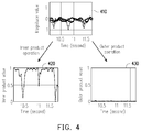
- FIG. 4 is a schematic diagram of calculating the inner product values and the outer product values according to the second three-axis acceleration values according to an embodiment of the invention.
- a chart 410 illustrates a corresponding relationship between each of the second three-axis acceleration values and the time axis.
- a chart 420 illustrates a plurality of inner product values calculated by the processing unit 130 according to each of the second three-axis acceleration values in the chart 410.
- a chart 430 illustrates a plurality of outer product values calculated by the processing unit 130 according to each of the second three-axis acceleration values in the chart 410.
- a pattern presented by each of the second three-axis acceleration values in the chart 410 corresponds to the walking status of the user.
- the chart 420 calculated by the processing unit 130 can still retain a pattern trend similar as that of the chart 410.
- a pattern trend of the chart 430 is quite different with that of the chart 410. Therefore, when the processing unit 130 determines that the user is in the walking status, the processing unit 130 calculates the number of steps according to the inner product values in the chart 420, so as to obtain an accurate step counting result.
- the second three-axis acceleration values calculated by the processing unit 130 present a larger fluctuation, and the second three-axis acceleration values have a larger noise.
- the processing unit 130 still calculates the number of steps according to the inner product values corresponding to the second three-axis acceleration values, a wrong number of steps is probably derived due to excessive noise.
- the number of steps is calculated according to the outer product values corresponding to the second three-axis acceleration values, the negative influence on determination of the number of steps caused by the noise can be effectively avoided, so as to produce the accurate step counting result.
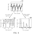
- FIG. 5 is a schematic diagram of calculating the inner product values and the outer product values according to the second three-axis acceleration values according to an embodiment of the invention.
- a chart 510 illustrates a corresponding relationship between each of the second three-axis acceleration values and the time axis.
- a chart 520 illustrates a plurality of inner product values calculated by the processing unit 130 according to each of the second three-axis acceleration values in the chart 510.
- a chart 530 illustrates a plurality of outer product values calculated by the processing unit 130 according to each of the second three-axis acceleration values in the chart 510.
- a pattern presented by each of the second three-axis acceleration values in the chart 510 corresponds to the running status of the user.
- the chart 530 calculated by the processing unit 130 can still retain a pattern trend similar as that of the chart 510.
- the processing unit 130 determines that the user is not in the walking status (i.e. in the running status)
- the processing unit 130 calculates the number of steps according to the outer product values in the chart 530, so as to obtain an accurate step counting result.
- FIG. 6 is a flowchart illustrating details of the embodiment of FIG. 2 .
- implementation details of the step S270 of FIG. 2 are introduced, though the invention is not limited thereto.
- the processing unit 130 filters noises in the reference values.
- the processing unit 130 performs a moving average (MA) operation to each of the reference values to calculate a moving average of each of the reference values.
- d 1 i is the moving average corresponding to the i th reference value
- d i is the i th reference value.
- step S620 the processing unit 130 calculates a plurality of slope values corresponding to the reference values.
- d 2 i is the slope value corresponding to the i th reference value.
- step S630 when plus and minus signs of two continuous slope values are different and a difference between the two continuous slope values is greater than a second predetermined threshold value (for example, 0.2), a counting value is accumulated, where the two continuous slope values are, for example, d 2 i and d 2 i - 1 (where i is any positive integer).
- a second predetermined threshold value for example, 0.2
- FIG. 7 is a schematic diagram of accumulating the counting value according to the slope values according to an embodiment of the invention.
- a chart 710 illustrates a corresponding relationship between each of the slope values and the time axis.
- Each of peak values 721-725 illustrated in a chart 720 corresponds to a time point when the plus and minus signs of two continuous slope values are different.
- the peak value 721 corresponds to a time point when the slope value is 0 (i.e. a time point when the slope value is changed from a positive value to a negative value).
- the peak value 722 corresponds to a time point when the slope value is 0 (i.e.
- the peak value 723 corresponds to a time point when the slope value is 0 (i.e. a time point when the slope value is changed from a positive value to a negative value).
- the peak value 724 corresponds to a time point when the slope value is 0 (i.e. a time point when the slope value is changed from a negative value to a positive value).
- the peak value 725 corresponds to a time point when the slope value is 0 (i.e. a time point when the slope value is changed from a positive value to a negative value).
- the processing unit 130 since the plus and minus signs of the two continuous slope values 711 and 712 are different and a difference between the two continuous slope values 711 and 712 is greater than the second predetermined threshold value (for example, 0.2), the processing unit 130 accumulates the counting value. Then, since the plus and minus signs of the two continuous slope values 713 and 714 are different and a difference between the two continuous slope values 713 and 714 is greater than the second predetermined threshold value (for example, 0.2), the processing unit 130 again accumulates the counting value.
- the second predetermined threshold value for example, 0.2
- the processing unit 130 does not accumulates the counting value. In this way, influence of the step counting result due to slight disturbance can be avoided.
- FIG. 8 is a schematic diagram of accumulating the counting value according to the slope values according to an embodiment of the invention.
- a chart 810 illustrates a corresponding relationship between each of the slope values and the time axis.
- Each of peak values 821-827 illustrated in a chart 820 corresponds to a time point when the plus and minus signs of two continuous slope values are different.
- the processing unit 130 since the plus and minus signs of the two continuous slope values 811 and 812 are different and a difference between the two continuous slope values 811 and 812 is greater than the second predetermined threshold value (for example, 0.2), the processing unit 130 accumulates the counting value. Then, since the plus and minus signs of the two continuous slope values 813 and 814 are different and a difference between the two continuous slope values 813 and 814 is greater than the second predetermined threshold value (for example, 0.2), the processing unit 130 again accumulates the counting value.
- the second predetermined threshold value for example, 0.2
- the processing unit 130 can divide the counting value by 2 to obtain the number of steps corresponding to the second three-axis acceleration values.
- the processing unit 130 can further execute steps S650-S670 to accurately calculate the corresponding number of steps.
- the processing unit 130 determines whether the average is between a first estimation value (for example, 0.2) and a second estimation value (for example, 0.5). If yes, the step S660 is executed, and if not, the step S670 is executed.
- a first estimation value for example, 0.2
- a second estimation value for example, 0.5
- the processing unit 130 can multiply the number of steps by a specific parameter to update the number of steps.
- the specific parameter is, for example, represented as: ⁇ motion ⁇ ⁇ walk ⁇ motion ⁇ ⁇ walk + ⁇
- a walk is the first estimation value
- a motion is the second estimation value
- ⁇ is an error rate estimation value (for example, 0.3).
- the processing unit 130 can multiply the number of steps by the specific parameter to correct the number of steps. In this way, the electronic apparatus 100 can still produce the correct step counting result when the user is changing the motion status.
- the processing unit 130 can maintain the number of steps.
- the processing unit 130 does not multiply the number of steps by the specific parameter to correct the number of steps.
- the method for counting steps of the invention can correctly generate the step counting result. Moreover, by adaptively multiplying the number of steps by the specific parameter, according to the method of the invention, the electronic apparatus 100 can still provide the correct step counting result when the user is changing the motion status.
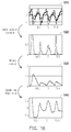
- FIG. 9 is a schematic diagram of counting steps according to the first three-axis acceleration values according to an embodiment of the invention.
- a chart 910 illustrates a corresponding relationship between each of the first three-axis acceleration values and the time axis.
- a chart 920 illustrates the inner product values corresponding to each of the first three-axis acceleration values in the chart 910.
- a chart 930 illustrates the moving averages corresponding to each of the inner product values in the chart 920.
- a chart 940 illustrates the slop values corresponding to each of the moving averages in the chart 930.
- the processing unit 130 can adopt the inner product values of the chart 920 to implement follow-up operations, so as to generate the correct step counting result.
- FIG. 10 is a schematic diagram of counting steps according to the first three-axis acceleration values according to an embodiment of the invention.
- a chart 1010 illustrates a corresponding relationship between each of the first three-axis acceleration values and the time axis.
- a chart 1020 illustrates the outer product values corresponding to each of the first three-axis acceleration values in the chart 1010.
- a chart 1030 illustrates the moving averages corresponding to each of the outer product values in the chart 1020.
- a chart 1040 illustrates the slop values corresponding to each of the moving averages in the chart 1030.
- the processing unit 130 can adopt the outer product values of the chart 1020 to implement follow-up operations, so as to generate the correct step counting result.
- the method for counting steps of the invention can be used to accurately generate the step counting result. Moreover, by adaptively multiplying the number of steps by the specific parameter, according to the method provided by the invention, the electronic apparatus can still provide the correct step counting result when the user is changing the motion status.
Landscapes
- Health & Medical Sciences (AREA)
- Physics & Mathematics (AREA)
- Life Sciences & Earth Sciences (AREA)
- Engineering & Computer Science (AREA)
- General Physics & Mathematics (AREA)
- Remote Sensing (AREA)
- Radar, Positioning & Navigation (AREA)
- Biomedical Technology (AREA)
- Surgery (AREA)
- Biophysics (AREA)
- Oral & Maxillofacial Surgery (AREA)
- Heart & Thoracic Surgery (AREA)
- Medical Informatics (AREA)
- Molecular Biology (AREA)
- Pathology (AREA)
- Animal Behavior & Ethology (AREA)
- General Health & Medical Sciences (AREA)
- Public Health (AREA)
- Veterinary Medicine (AREA)
- Dentistry (AREA)
- Physiology (AREA)
- Measurement Of The Respiration, Hearing Ability, Form, And Blood Characteristics Of Living Organisms (AREA)
- Measurement Of Distances Traversed On The Ground (AREA)
Claims (10)
- Une méthode de comptage de pas, adaptée à un appareil électronique (100), la méthode de comptage de pas comprenant :l'obtention (S210) d'une orientation et d'une pluralité de premières valeurs d'accélération suivant trois axes de l'appareil électronique (100) ;la suppression (S220) d'un rapport spécifique d'une accélération gravitationnelle de chacune des premières valeurs d'accélération suivant trois axes selon l'orientation pour générer une pluralité de secondes valeurs d'accélération suivant trois axes;le calcul (S230) d'une pluralité de valeurs de produits intrinsèques et d'une pluralité de valeurs de produits extrinsèques selon les secondes valeurs d'accélération suivant trois axes ;la détermination (S240) du fait de savoir si un utilisateur de l'appareil électronique (100) est dans un mode de marche selon les secondes valeurs d'accélération suivant trois axes ;dans l'affirmative, la fixation (S250) des valeurs de produits intrinsèques en tant que valeurs de référence ;dans la négative, la fixation (S260) des valeurs de produits extrinsèques en tant que valeurs de référence ; etle calcul (S270) d'un nombre de pas correspondant aux secondes valeurs d'accélération suivant trois axes en fonction des valeurs de références.
- La méthode de comptage de pas telle que revendiquée dans la revendication 1, dans laquelle l'étape de détermination du fait de savoir si l'utilisateur de l'appareil électronique (100) est dans un mode de marche en fonction des secondes valeurs d'accélération suivant trois axes comporte :la calcul d'une pluralité d'amplitudes correspondant aux secondes valeurs d'accélération suivant trois axes ;le calcul d'une moyenne des valeurs d'amplitudes ; etla détermination de savoir si la moyenne est supérieure à un premier seuil ;dans l'affirmative, la détermination du fait de savoir si l'utilisateur est dans le mode de marche ; etdans la négative la détermination du fait de savoir si l'utilisateur n'est pas dans le mode de marche.
- La méthode de comptage de pas telle que revendiquée dans la revendication 1 ou 2, dans laquelle l'étape de calcul du nombre de pas correspondant aux secondes valeurs d'accélération suivant trois axes en fonction des valeurs de références comporte :le filtrage (S610) d'un bruit au sein des valeurs de références ;le calcul (S620) d'une pluralité de valeurs de pentes correspondant aux valeurs de référence ;l'accumulation (S630) d'une valeur de comptage lorsque sont distinctes les signes positifs et négatifs des valeurs de pentes continues au sein des valeurs de pentes et lorsqu'une différence entre les deux valeurs de pentes continues est supérieure à un second seuil prédéterminé ; etla division (S640) de la valeur de comptage par 2 afin d'obtenir un nombre de pas correspondant aux secondes valeurs d'accélération suivant les trois axes.
- La méthode de comptage de pas telle que revendiquée dans l'une quelconque des revendications 1 à 3, dans laquelle à la suite de l'étape de division par 2 de la valeur de comptage dans le but d'obtenir le nombre de pas correspondant aux secondes valeurs d'accélération suivant trois axes, la méthode comporte en outre :la détermination (S650) du fait de savoir si la moyenne se situe entre une première valeur estimée et une seconde valeur estimée ;dans l'affirmative, la multiplication (S660) du nombre de pas par un paramètre spécifique pour mettre à jour le nombre de pas ; etdans la négative, le maintien inchangé (S670) du nombre de pas.
- La méthode de comptage de pas telle que revendiquée dans l'une quelconque des revendications 1 à 4, dans laquelle le paramètre spécifique est :
 est une valeur estimée de taux d'erreur.
- Un appareil électronique (100), comprenant :une unité de détection (110), détectant une orientation et une pluralité de premières valeurs d'accélération suivant trois axes de l'appareil électronique (100) ;une unité de stockage (120), pour le stockage d'une pluralité de modules ; etune unité de traitement (130), couplée à l'unité de détection (110) et à l'unité de stockage, et accédant aux modules en vue de l'exécution des étapes suivantes ;l'obtention (S210) d'une orientation et d'une pluralité de premières valeurs d'accélération suivant trois axes de l'appareil électronique (100) ;la suppression (S220) d'un rapport spécifique d'une accélération gravitationnelle de chacune des premières valeurs d'accélération suivant trois axes selon l'orientation dans le but de générer une pluralité de secondes valeurs d'accélération suivant trois axes;le calcul (S230) d'une pluralité de valeurs de produits intrinsèques et d'une pluralité de valeurs de produits extrinsèques selon les secondes valeurs d'accélération suivant trois axes ;la détermination (S240) du fait de savoir si un utilisateur de l'appareil électronique (100) est dans un mode de marche selon les secondes valeurs d'accélération suivant trois axes ;dans l'affirmative, la fixation (S250) des valeurs de produits intrinsèques en tant que valeurs de référence ;dans la négative, la fixation (S260) des valeurs de produits extrinsèques en tant que valeurs de référence ; etle calcul (S270) d'un nombre de pas correspondant aux secondes valeurs d'accélération suivant trois axes en fonction des valeurs de références.
- L'appareil électronique (100) tel que revendiqué dans la revendication 6, dans lequel l'unité de traitement (130) est configuré pour :calculer une pluralité d'amplitudes correspondant aux secondes valeurs d'accélération suivant trois axes ;calculer une moyenne des valeurs d'amplitudes ; etdéterminer si la moyenne est supérieure à un premier seuil ;dans l'affirmative, déterminer si l'utilisateur est dans le mode de marche ; etdans la négative, déterminer si l'utilisateur n'est pas dans le mode de marche.
- L'appareil électronique (100) tel que revendiqué dans la revendication 6 ou 7, dans lequel l'unité de traitement (130) est configuré pour :filtrer (S610) un bruit au sein des valeurs de références ;calculer (S620) une pluralité de valeurs de pentes correspondant aux valeurs de référence ;accumuler (S630) une valeur de comptage lorsque sont distinctes les signes positifs et négatifs des valeurs de pentes continues au sein des valeurs de pentes et lorsqu'une différence entre les deux valeurs de pentes continues est supérieure à un second seuil prédéterminé ; etdiviser (S640) la valeur de comptage par 2 afin d'obtenir un nombre de pas correspondant aux secondes valeurs d'accélération suivant les trois axes.
- L'appareil électronique (100) tel que revendiqué dans la revendication 8, dans lequel l'unité de traitement (130) est configurée pour :déterminer (S650) si la moyenne se situe entre une première valeur estimée et une seconde valeur estimée ;dans l'affirmative, multiplier (S660) le nombre de pas par un paramètre spécifique pour mettre à jour le nombre de pas ; etdans la négative, maintenir inchangé (S670) le nombre de pas.
- L'appareil électronique (100) tel que revendiqué dans la revendication 9, dans lequel le paramètre spécifique est :
 est une valeur estimée de taux d'erreur.
Applications Claiming Priority (1)
| Application Number | Priority Date | Filing Date | Title |
|---|---|---|---|
| TW103106314A TWI502167B (zh) | 2014-02-25 | 2014-02-25 | 計步方法及其電子裝置 |
Publications (2)
| Publication Number | Publication Date |
|---|---|
| EP2910954A1 EP2910954A1 (fr) | 2015-08-26 |
| EP2910954B1 true EP2910954B1 (fr) | 2016-04-13 |
Family
ID=52577654
Family Applications (1)
| Application Number | Title | Priority Date | Filing Date |
|---|---|---|---|
| EP15155635.4A Not-in-force EP2910954B1 (fr) | 2014-02-25 | 2015-02-18 | Procédé de comptage de pas et appareil électronique utilisant celui-ci |
Country Status (3)
| Country | Link |
|---|---|
| US (1) | US20150241243A1 (fr) |
| EP (1) | EP2910954B1 (fr) |
| TW (1) | TWI502167B (fr) |
Families Citing this family (6)
| Publication number | Priority date | Publication date | Assignee | Title |
|---|---|---|---|---|
| US20160179218A1 (en) * | 2014-12-23 | 2016-06-23 | Intel Corporation | Systems and methods for improving the quality of motion sensor generated user input to mobile devices |
| WO2017065089A1 (fr) * | 2015-10-15 | 2017-04-20 | アルプス電気株式会社 | Dispositif de mesure de comptage de pas et programme de mesure de comptage de pas |
| CN105953794B (zh) * | 2016-04-26 | 2018-10-19 | 杭州欣晟达信息技术有限公司 | 一种基于mems传感器的计步导航方法 |
| CN107144291B (zh) * | 2017-05-23 | 2019-11-05 | 维沃移动通信有限公司 | 一种数据处理方法及移动终端 |
| TWI640751B (zh) * | 2017-06-09 | 2018-11-11 | 研鼎智能股份有限公司 | Step counting method |
| CN110132303A (zh) * | 2019-05-21 | 2019-08-16 | 出门问问信息科技有限公司 | 计步测试数据采集方法、存储介质和电子设备 |
Family Cites Families (6)
| Publication number | Priority date | Publication date | Assignee | Title |
|---|---|---|---|---|
| KR100571849B1 (ko) * | 2005-02-04 | 2006-04-17 | 삼성전자주식회사 | 보행자의 보행 횟수 계수방법 및 장치 |
| TWI273442B (en) * | 2005-08-23 | 2007-02-11 | Far Eastone Telecomm Co Ltd | Method for determining a moving object entering a specific geographic zone, and recording medium having software programs for executing the same |
| JP4904861B2 (ja) * | 2006-03-14 | 2012-03-28 | ソニー株式会社 | 体動検出装置、体動検出方法および体動検出プログラム |
| JP4644274B2 (ja) * | 2008-07-29 | 2011-03-02 | 京セラ株式会社 | 携帯機器、歩数カウント方法および重力方向検出方法 |
| CN102484660B (zh) * | 2010-01-07 | 2014-06-11 | 株式会社东芝 | 移动状态推测装置、方法及程序 |
| US8694251B2 (en) * | 2010-11-25 | 2014-04-08 | Texas Instruments Incorporated | Attitude estimation for pedestrian navigation using low cost mems accelerometer in mobile applications, and processing methods, apparatus and systems |
-
2014
- 2014-02-25 TW TW103106314A patent/TWI502167B/zh not_active IP Right Cessation
-
2015
- 2015-02-10 US US14/617,940 patent/US20150241243A1/en not_active Abandoned
- 2015-02-18 EP EP15155635.4A patent/EP2910954B1/fr not_active Not-in-force
Also Published As
| Publication number | Publication date |
|---|---|
| US20150241243A1 (en) | 2015-08-27 |
| TWI502167B (zh) | 2015-10-01 |
| EP2910954A1 (fr) | 2015-08-26 |
| TW201533429A (zh) | 2015-09-01 |
Similar Documents
| Publication | Publication Date | Title |
|---|---|---|
| EP2910954B1 (fr) | Procédé de comptage de pas et appareil électronique utilisant celui-ci | |
| US8589113B2 (en) | Movement detection device, electronic device, movement detection method and storage medium stored with a program | |
| EP2653957B1 (fr) | Dispositif de détection de mouvement de fonctionnement, procédé de détection de mouvement de fonctionnement et programme correspondant | |
| EP2899547B1 (fr) | Procédé et appareil pour déterminer l'accélération d'un véhicule | |
| US8942950B2 (en) | Motion detection device, electronic device, motion detection method, and program storage medium | |
| US20150317890A1 (en) | Detecting changes in position of a device in a horizontal or vertical direction | |
| JP5417970B2 (ja) | 歩数計及び歩数計数方法 | |
| EP2807452A1 (fr) | Méthodologie d'étalonnage automatique en utilisation pour capteurs de dispositifs mobiles | |
| US10309983B2 (en) | Systems and methods for motion detection | |
| US9702899B2 (en) | Pedometer with lag correction | |
| US10324108B2 (en) | Dynamic offset correction for calibration of MEMS sensor | |
| CN209186713U (zh) | 用于表征运动的设备 | |
| WO2012169051A1 (fr) | Appareil et procédé de détermination d'une chute | |
| Sarbishei | On the accuracy improvement of low-power orientation filters using IMU and MARG sensor arrays | |
| CN109425364B (zh) | 利用假阳性拒绝的用于执行计步的电子设备 | |
| KR101639351B1 (ko) | 웨어러블 입력 시스템 및 모션 인식 방법 | |
| JP7215144B2 (ja) | 計測装置、計測方法及び計測プログラム | |
| JP6848571B2 (ja) | 姿勢算出装置、姿勢計測システム、及び姿勢算出方法 | |
| CN104880198A (zh) | 计步方法及其电子装置 | |
| CN111625755B (zh) | 数据处理方法、装置、服务器、终端和可读存储介质 | |
| WO2014191803A1 (fr) | Détection et classification d'activités de marche basées sur l'accélération, sur des dispositifs mobiles | |
| EP3514498B1 (fr) | Dispositif de mesure de quantité physique | |
| CN108731675A (zh) | 待定位物航向变化量的测量方法、测量装置和电子设备 | |
| JP7120361B2 (ja) | 補正装置、姿勢算出装置、補正方法、及び、プログラム | |
| EP3224575B1 (fr) | Dispositifs de comptage de pas et procédés de comptage de pas |
Legal Events
| Date | Code | Title | Description |
|---|---|---|---|
| PUAI | Public reference made under article 153(3) epc to a published international application that has entered the european phase |
Free format text: ORIGINAL CODE: 0009012 |
|
| AK | Designated contracting states |
Kind code of ref document: A1 Designated state(s): AL AT BE BG CH CY CZ DE DK EE ES FI FR GB GR HR HU IE IS IT LI LT LU LV MC MK MT NL NO PL PT RO RS SE SI SK SM TR |
|
| AX | Request for extension of the european patent |
Extension state: BA ME |
|
| 17P | Request for examination filed |
Effective date: 20150727 |
|
| RBV | Designated contracting states (corrected) |
Designated state(s): AL AT BE BG CH CY CZ DE DK EE ES FI FR GB GR HR HU IE IS IT LI LT LU LV MC MK MT NL NO PL PT RO RS SE SI SK SM TR |
|
| GRAP | Despatch of communication of intention to grant a patent |
Free format text: ORIGINAL CODE: EPIDOSNIGR1 |
|
| INTG | Intention to grant announced |
Effective date: 20151029 |
|
| GRAS | Grant fee paid |
Free format text: ORIGINAL CODE: EPIDOSNIGR3 |
|
| GRAA | (expected) grant |
Free format text: ORIGINAL CODE: 0009210 |
|
| AK | Designated contracting states |
Kind code of ref document: B1 Designated state(s): AL AT BE BG CH CY CZ DE DK EE ES FI FR GB GR HR HU IE IS IT LI LT LU LV MC MK MT NL NO PL PT RO RS SE SI SK SM TR |
|
| REG | Reference to a national code |
Ref country code: GB Ref legal event code: FG4D |
|
| REG | Reference to a national code |
Ref country code: AT Ref legal event code: REF Ref document number: 790702 Country of ref document: AT Kind code of ref document: T Effective date: 20160415 Ref country code: CH Ref legal event code: EP |
|
| REG | Reference to a national code |
Ref country code: IE Ref legal event code: FG4D |
|
| REG | Reference to a national code |
Ref country code: DE Ref legal event code: R096 Ref document number: 602015000012 Country of ref document: DE |
|
| REG | Reference to a national code |
Ref country code: LT Ref legal event code: MG4D |
|
| REG | Reference to a national code |
Ref country code: AT Ref legal event code: MK05 Ref document number: 790702 Country of ref document: AT Kind code of ref document: T Effective date: 20160413 |
|
| REG | Reference to a national code |
Ref country code: NL Ref legal event code: MP Effective date: 20160413 |
|
| PG25 | Lapsed in a contracting state [announced via postgrant information from national office to epo] |
Ref country code: LT Free format text: LAPSE BECAUSE OF FAILURE TO SUBMIT A TRANSLATION OF THE DESCRIPTION OR TO PAY THE FEE WITHIN THE PRESCRIBED TIME-LIMIT Effective date: 20160413 Ref country code: NL Free format text: LAPSE BECAUSE OF FAILURE TO SUBMIT A TRANSLATION OF THE DESCRIPTION OR TO PAY THE FEE WITHIN THE PRESCRIBED TIME-LIMIT Effective date: 20160413 Ref country code: FI Free format text: LAPSE BECAUSE OF FAILURE TO SUBMIT A TRANSLATION OF THE DESCRIPTION OR TO PAY THE FEE WITHIN THE PRESCRIBED TIME-LIMIT Effective date: 20160413 Ref country code: PL Free format text: LAPSE BECAUSE OF FAILURE TO SUBMIT A TRANSLATION OF THE DESCRIPTION OR TO PAY THE FEE WITHIN THE PRESCRIBED TIME-LIMIT Effective date: 20160413 Ref country code: NO Free format text: LAPSE BECAUSE OF FAILURE TO SUBMIT A TRANSLATION OF THE DESCRIPTION OR TO PAY THE FEE WITHIN THE PRESCRIBED TIME-LIMIT Effective date: 20160713 |
|
| PG25 | Lapsed in a contracting state [announced via postgrant information from national office to epo] |
Ref country code: GR Free format text: LAPSE BECAUSE OF FAILURE TO SUBMIT A TRANSLATION OF THE DESCRIPTION OR TO PAY THE FEE WITHIN THE PRESCRIBED TIME-LIMIT Effective date: 20160714 Ref country code: PT Free format text: LAPSE BECAUSE OF FAILURE TO SUBMIT A TRANSLATION OF THE DESCRIPTION OR TO PAY THE FEE WITHIN THE PRESCRIBED TIME-LIMIT Effective date: 20160816 Ref country code: ES Free format text: LAPSE BECAUSE OF FAILURE TO SUBMIT A TRANSLATION OF THE DESCRIPTION OR TO PAY THE FEE WITHIN THE PRESCRIBED TIME-LIMIT Effective date: 20160413 Ref country code: RS Free format text: LAPSE BECAUSE OF FAILURE TO SUBMIT A TRANSLATION OF THE DESCRIPTION OR TO PAY THE FEE WITHIN THE PRESCRIBED TIME-LIMIT Effective date: 20160413 Ref country code: HR Free format text: LAPSE BECAUSE OF FAILURE TO SUBMIT A TRANSLATION OF THE DESCRIPTION OR TO PAY THE FEE WITHIN THE PRESCRIBED TIME-LIMIT Effective date: 20160413 Ref country code: SE Free format text: LAPSE BECAUSE OF FAILURE TO SUBMIT A TRANSLATION OF THE DESCRIPTION OR TO PAY THE FEE WITHIN THE PRESCRIBED TIME-LIMIT Effective date: 20160413 Ref country code: AT Free format text: LAPSE BECAUSE OF FAILURE TO SUBMIT A TRANSLATION OF THE DESCRIPTION OR TO PAY THE FEE WITHIN THE PRESCRIBED TIME-LIMIT Effective date: 20160413 Ref country code: LV Free format text: LAPSE BECAUSE OF FAILURE TO SUBMIT A TRANSLATION OF THE DESCRIPTION OR TO PAY THE FEE WITHIN THE PRESCRIBED TIME-LIMIT Effective date: 20160413 |
|
| PG25 | Lapsed in a contracting state [announced via postgrant information from national office to epo] |
Ref country code: BE Free format text: LAPSE BECAUSE OF FAILURE TO SUBMIT A TRANSLATION OF THE DESCRIPTION OR TO PAY THE FEE WITHIN THE PRESCRIBED TIME-LIMIT Effective date: 20160413 Ref country code: IT Free format text: LAPSE BECAUSE OF FAILURE TO SUBMIT A TRANSLATION OF THE DESCRIPTION OR TO PAY THE FEE WITHIN THE PRESCRIBED TIME-LIMIT Effective date: 20160413 |
|
| REG | Reference to a national code |
Ref country code: FR Ref legal event code: PLFP Year of fee payment: 3 |
|
| REG | Reference to a national code |
Ref country code: DE Ref legal event code: R097 Ref document number: 602015000012 Country of ref document: DE |
|
| PG25 | Lapsed in a contracting state [announced via postgrant information from national office to epo] |
Ref country code: EE Free format text: LAPSE BECAUSE OF FAILURE TO SUBMIT A TRANSLATION OF THE DESCRIPTION OR TO PAY THE FEE WITHIN THE PRESCRIBED TIME-LIMIT Effective date: 20160413 Ref country code: CZ Free format text: LAPSE BECAUSE OF FAILURE TO SUBMIT A TRANSLATION OF THE DESCRIPTION OR TO PAY THE FEE WITHIN THE PRESCRIBED TIME-LIMIT Effective date: 20160413 Ref country code: DK Free format text: LAPSE BECAUSE OF FAILURE TO SUBMIT A TRANSLATION OF THE DESCRIPTION OR TO PAY THE FEE WITHIN THE PRESCRIBED TIME-LIMIT Effective date: 20160413 Ref country code: SK Free format text: LAPSE BECAUSE OF FAILURE TO SUBMIT A TRANSLATION OF THE DESCRIPTION OR TO PAY THE FEE WITHIN THE PRESCRIBED TIME-LIMIT Effective date: 20160413 Ref country code: RO Free format text: LAPSE BECAUSE OF FAILURE TO SUBMIT A TRANSLATION OF THE DESCRIPTION OR TO PAY THE FEE WITHIN THE PRESCRIBED TIME-LIMIT Effective date: 20160413 |
|
| PLBE | No opposition filed within time limit |
Free format text: ORIGINAL CODE: 0009261 |
|
| STAA | Information on the status of an ep patent application or granted ep patent |
Free format text: STATUS: NO OPPOSITION FILED WITHIN TIME LIMIT |
|
| PG25 | Lapsed in a contracting state [announced via postgrant information from national office to epo] |
Ref country code: SM Free format text: LAPSE BECAUSE OF FAILURE TO SUBMIT A TRANSLATION OF THE DESCRIPTION OR TO PAY THE FEE WITHIN THE PRESCRIBED TIME-LIMIT Effective date: 20160413 |
|
| 26N | No opposition filed |
Effective date: 20170116 |
|
| PG25 | Lapsed in a contracting state [announced via postgrant information from national office to epo] |
Ref country code: SI Free format text: LAPSE BECAUSE OF FAILURE TO SUBMIT A TRANSLATION OF THE DESCRIPTION OR TO PAY THE FEE WITHIN THE PRESCRIBED TIME-LIMIT Effective date: 20160413 |
|
| PG25 | Lapsed in a contracting state [announced via postgrant information from national office to epo] |
Ref country code: MC Free format text: LAPSE BECAUSE OF FAILURE TO SUBMIT A TRANSLATION OF THE DESCRIPTION OR TO PAY THE FEE WITHIN THE PRESCRIBED TIME-LIMIT Effective date: 20160413 |
|
| REG | Reference to a national code |
Ref country code: IE Ref legal event code: MM4A |
|
| PG25 | Lapsed in a contracting state [announced via postgrant information from national office to epo] |
Ref country code: LU Free format text: LAPSE BECAUSE OF NON-PAYMENT OF DUE FEES Effective date: 20170218 |
|
| REG | Reference to a national code |
Ref country code: FR Ref legal event code: PLFP Year of fee payment: 4 |
|
| PG25 | Lapsed in a contracting state [announced via postgrant information from national office to epo] |
Ref country code: IE Free format text: LAPSE BECAUSE OF NON-PAYMENT OF DUE FEES Effective date: 20170218 |
|
| REG | Reference to a national code |
Ref country code: CH Ref legal event code: PL |
|
| PG25 | Lapsed in a contracting state [announced via postgrant information from national office to epo] |
Ref country code: MT Free format text: LAPSE BECAUSE OF NON-PAYMENT OF DUE FEES Effective date: 20170218 |
|
| PG25 | Lapsed in a contracting state [announced via postgrant information from national office to epo] |
Ref country code: AL Free format text: LAPSE BECAUSE OF FAILURE TO SUBMIT A TRANSLATION OF THE DESCRIPTION OR TO PAY THE FEE WITHIN THE PRESCRIBED TIME-LIMIT Effective date: 20160413 |
|
| PG25 | Lapsed in a contracting state [announced via postgrant information from national office to epo] |
Ref country code: LI Free format text: LAPSE BECAUSE OF NON-PAYMENT OF DUE FEES Effective date: 20180228 Ref country code: CH Free format text: LAPSE BECAUSE OF NON-PAYMENT OF DUE FEES Effective date: 20180228 |
|
| PG25 | Lapsed in a contracting state [announced via postgrant information from national office to epo] |
Ref country code: HU Free format text: LAPSE BECAUSE OF FAILURE TO SUBMIT A TRANSLATION OF THE DESCRIPTION OR TO PAY THE FEE WITHIN THE PRESCRIBED TIME-LIMIT; INVALID AB INITIO Effective date: 20150218 |
|
| PG25 | Lapsed in a contracting state [announced via postgrant information from national office to epo] |
Ref country code: BG Free format text: LAPSE BECAUSE OF FAILURE TO SUBMIT A TRANSLATION OF THE DESCRIPTION OR TO PAY THE FEE WITHIN THE PRESCRIBED TIME-LIMIT Effective date: 20160413 |
|
| PG25 | Lapsed in a contracting state [announced via postgrant information from national office to epo] |
Ref country code: CY Free format text: LAPSE BECAUSE OF FAILURE TO SUBMIT A TRANSLATION OF THE DESCRIPTION OR TO PAY THE FEE WITHIN THE PRESCRIBED TIME-LIMIT Effective date: 20160413 |
|
| PG25 | Lapsed in a contracting state [announced via postgrant information from national office to epo] |
Ref country code: MK Free format text: LAPSE BECAUSE OF FAILURE TO SUBMIT A TRANSLATION OF THE DESCRIPTION OR TO PAY THE FEE WITHIN THE PRESCRIBED TIME-LIMIT Effective date: 20160413 |
|
| PG25 | Lapsed in a contracting state [announced via postgrant information from national office to epo] |
Ref country code: TR Free format text: LAPSE BECAUSE OF FAILURE TO SUBMIT A TRANSLATION OF THE DESCRIPTION OR TO PAY THE FEE WITHIN THE PRESCRIBED TIME-LIMIT Effective date: 20160413 |
|
| PG25 | Lapsed in a contracting state [announced via postgrant information from national office to epo] |
Ref country code: IS Free format text: LAPSE BECAUSE OF FAILURE TO SUBMIT A TRANSLATION OF THE DESCRIPTION OR TO PAY THE FEE WITHIN THE PRESCRIBED TIME-LIMIT Effective date: 20160813 |
|
| PGFP | Annual fee paid to national office [announced via postgrant information from national office to epo] |
Ref country code: DE Payment date: 20240116 Year of fee payment: 10 Ref country code: GB Payment date: 20240118 Year of fee payment: 10 |
|
| PGFP | Annual fee paid to national office [announced via postgrant information from national office to epo] |
Ref country code: FR Payment date: 20240123 Year of fee payment: 10 |
|
| REG | Reference to a national code |
Ref country code: DE Ref legal event code: R119 Ref document number: 602015000012 Country of ref document: DE |
|
| GBPC | Gb: european patent ceased through non-payment of renewal fee |
Effective date: 20250218 |
|
| PG25 | Lapsed in a contracting state [announced via postgrant information from national office to epo] |
Ref country code: DE Free format text: LAPSE BECAUSE OF NON-PAYMENT OF DUE FEES Effective date: 20250902 |
|
| PG25 | Lapsed in a contracting state [announced via postgrant information from national office to epo] |
Ref country code: GB Free format text: LAPSE BECAUSE OF NON-PAYMENT OF DUE FEES Effective date: 20250218 |
|
| PG25 | Lapsed in a contracting state [announced via postgrant information from national office to epo] |
Ref country code: FR Free format text: LAPSE BECAUSE OF NON-PAYMENT OF DUE FEES Effective date: 20250228 |