EP2910976A1 - Dispositif de vérification et procédé de détection d'une contamination de surface sur des objets allongés - Google Patents
Dispositif de vérification et procédé de détection d'une contamination de surface sur des objets allongés Download PDFInfo
- Publication number
- EP2910976A1 EP2910976A1 EP15155422.7A EP15155422A EP2910976A1 EP 2910976 A1 EP2910976 A1 EP 2910976A1 EP 15155422 A EP15155422 A EP 15155422A EP 2910976 A1 EP2910976 A1 EP 2910976A1
- Authority
- EP
- European Patent Office
- Prior art keywords
- test device
- detectors
- detector
- elongated
- elongate
- Prior art date
- Legal status (The legal status is an assumption and is not a legal conclusion. Google has not performed a legal analysis and makes no representation as to the accuracy of the status listed.)
- Granted
Links
Images


Classifications
-
- G—PHYSICS
- G01—MEASURING; TESTING
- G01T—MEASUREMENT OF NUCLEAR OR X-RADIATION
- G01T1/00—Measuring X-radiation, gamma radiation, corpuscular radiation, or cosmic radiation
- G01T1/16—Measuring radiation intensity
- G01T1/167—Measuring radioactive content of objects, e.g. contamination
Definitions
- the present invention relates to a device for detecting surface contamination on elongate objects according to the preamble of claim 1;
- This device is also referred to as a test device in connection with the invention.
- part of the invention is a method for detecting surface contamination on elongate objects according to the preamble of claim 9 and a control device for a Inventive test device according to the preamble of claim 11.
- contamination measuring instruments are available, which are designed as hand-held measuring instruments. Therefore, the quality of the measurements depends largely on the operator of the meter. In addition, with these measuring devices measurements on single or multiple curved surfaces only partially possible, or require a lot of time.
- the metrological problem on such objects are different (measuring) distances between the measuring device and the surface section to be tested, because a detector of the measuring device generally does not completely cover the surface of the tube to be tested in a setting or position. Only a few centimeters remain as effective measuring surface, the detection or the measurement is often incomplete.
- the currently used analog contamination meters are not able to save the measurement results and output logs.
- the connection to a communication network for evaluation is not provided, and this is required in DIN ISO 25457-1.
- the WO 2010/046106 A1 shows a tester and a test method for material testing of elongate objects.
- the elongated object passes through a detection element, which is designed as a continuous coil.
- the intended measurements can be carried out without contact.
- JP H01-116 481 A For example, a device is known with the aid of which it is possible to detect the beta rays emitted by the surface of a drum in an interferometer. This device is not suitable for testing pipes or other elongate articles of relatively small diameter and consequently of a small radius of curvature.
- the object of the present invention is to provide a test device with a corresponding method, wherein a surface contamination can be determined with an accuracy that meets the legal requirements automatically on pipes, rods and cables with different diameters.
- the detectors are used to detect an ionizing (radioactive) radiation, wherein signals of the detectors are evaluated by a special measuring electronics.
- a special measuring electronics Preferably, three, four or even five to ten detectors are provided, which are arranged on the circumference of the elongated object. Preference is given to using small-sized, in particular narrow, detectors.
- the number of detectors, the distance between the detectors and the distance between the detectors and the elongated object are dependent on eg the cross-sectional profile or the diameter of the elongated object to be tested.
- the detection limit is significant over which - depending on the diameter of the elongated object - the maximum distance between the detectors and the elongate object can be automatically calculated and adjusted accordingly.
- the detectors can be adjusted such that the predetermined distance to the elongate object is reached or undershot.
- the elongated object is positioned against fixed detectors.
- the arrangement of the detectors is adapted to the circumference of the elongate object and the elongate object is subsequently positioned at the calculated distance. All these functions can preferably be carried out automatically by appropriately designed devices.
- a rotating device can rotate the elongate object on a support table about the longitudinal axis.
- a plurality of detectors in the circumferential direction at an equal distance from elongated object are arranged.
- a plurality of detectors can be arranged one after the other in the longitudinal direction of the elongated object in the test apparatus.
- the distance corresponds to a maximum of the distance, which is determined by the detection limit.
- a defined test section is defined on the circumference of the elongated object.
- the elongate object can be further advanced in the longitudinal direction by a predetermined length through the inspection device and a new, subsequent circumferential path can be detected.
- At least one detector may be arranged in a distance to the elongated object which deviates from at least one other detector.
- an offset arrangement of detectors can be provided, which is arranged on a smaller peripheral surface of the elongated object.
- the test device is suitable for elongated objects with almost any diameter. Prefers however, a diameter of> 6 cm is suitable.
- the elongate objects may be tubes, rods, rods or cables, in particular power cables.
- objects that have just been formed are detected with the testing device.
- the test apparatus may also include an inner tube detector, which detects a surface contamination in the interior of a tube at the same time or with a time offset.
- the at least one detector comprises a beta detector which detects a beta radiation.
- gamma detectors could also be used which detect the spectrum of gamma radiation from a source of ionizing radiation.
- the test apparatus comprises or is connected to a memory device for storing detection results and a data processing device.
- the data processing device can be designed, for example, as a microprocessor and can comprise a computer program which is also programmed for the application of the method according to the invention.
- the data processing device may also, for example, a database in the storage device manage in which the results are stored.
- the database or the memory device can be integrated into a communication network for further processing of the detection results via corresponding devices.
- the memory element and / or the data processing device can also be arranged, for example, on an external personal computer.
- the test apparatus comprises an output device for outputting the detection results or for printing release documents.
- the testing device can serve as a "clearance measuring station" according to ⁇ 29 StrlSchV.
- ⁇ 29 StrlSchV radioactive substances that are contaminated may only be used or disposed of as non-radioactive substances if the competent authority issues a release with the corresponding release documents. This can only happen if the clearance values specified in the Radiation Protection Ordinance are exceeded, which is determined by the method according to the invention and documented in the release documents.
- test device is part of a communication network.
- the storage device, the data processing device and / or the output device also be integrated externally in the communication network.
- the inventive method the time and personnel costs in the contamination measurement is significantly reduced. Often many kilometers of piping, rods, rods and power cables are detected. In addition, the reliability of the detection results is greatly improved by the inventive method.
- the documents or protocols required for the release process are created automatically.
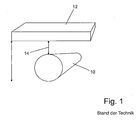
- FIG. 1 shows in a schematic representation of an elongated object 10, which is formed as a tube.
- a detector 12 is guided over the entire surface of the object 10 at a predetermined distance 14.
- the distance 14 corresponds essentially to a detection limit for measurements of ionizing (radioactive) radiation, which can be determined according to DIN ISO 11929.
- the detection limit is dependent on the diameter of the elongate object 10.
- the detector 12 is usually hand-held, so that large measurement inaccuracies are unavoidable.
- One Log of the detected measured values can not be output automatically.
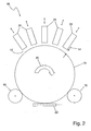
- FIG. 2 shows a test device 16 according to the invention in a schematic representation and in a first embodiment.
- an elongate object 10 for example a pipe, a rod, a rod or a cable, in particular a power cable
- the elongate object 10 can be mounted so as to be movable in the longitudinal direction and / or in the circumferential direction.
- the elongate object 10 can be rotated in the circumferential direction via rotatable rollers 18 (see arrow 20).
- a longitudinal feed 22 for example by rollers, a movable carriage or a conveyor belt, can be moved.
- the rotation by the rollers 18 and the feed in the longitudinal direction by the longitudinal feed 22 can be carried out continuously or stepwise and sequentially.
- at least the movement through the longitudinal feed 22 is stepwise.
- the test apparatus 16 is provided for detecting surface contamination on elongated articles 10 of almost any diameter.
- detectors 24 in the arranged by the measurement rules given distance 14 to the elongated object 10.
- the detectors are used for detecting an ionizing radiation, wherein signals of the detectors 24 by a transmitter 28 (see FIG. 5 ) be evaluated.
- signals of the detectors 24 by a transmitter 28 Preferably, five to ten detectors 24 are provided.
- the distance 14 is known to be determined according to the specifications of DIN ISO 11929 and corresponds to a maximum of the detection limit, which is dependent on the diameter of the elongate object 10 (see also explanation to FIG. 1 ).
- the calculation of the detection limit can be carried out, for example, in the evaluation electronics 28.
- the detectors 24 can be moved in the radial direction. This is indicated by the double arrows (without reference numeral) in the Figures 2 and 3 indicated.
- the adjustment of the distance 14 between the detectors 24 and the article 10 may be manual or automatic. The latter alternative is preferred, because it saves working time and also the correct setting of the distance 14 can be automatically recorded and documented.
- a distance and an arrangement of the individual detectors 24 to each other are uniformly formed in this embodiment.
- the detectors 24 are particularly compact and narrow.
- five detectors 24 are provided which cover a circumferential angle of about 120 °.
- the number of detectors 24 and their arrangement around the article 10 can also be chosen differently.
- three detectors 24 can be arranged at a distance of 120 °.
- the detectors 24 can be controlled by a controller 26 acting radially to the elongate object 10 (see FIG Fig. 4 ) are spatially adjusted so that the distance 14 is adjustable. It is also possible that the article 10 is positioned relative to fixed detectors 24.
- the arrangement of the detectors 24 is adapted to the diameter of the article 10 and the article 10 is then positioned in the calculated distance 14. This can happen, for example, by a vertical displacement of the longitudinal feed 22. These functions are preferably carried out automatically.
- beta detectors particularly preferred is the use of beta detectors.
- Gamma detectors could also be used.
- the method according to the invention can be executed in a control device 30.
- the control device 30 (see FIG. 4 ) is designed, for example, as a measuring computer with a data processing device, which additionally has a Memory device 32 (see Fig. 4 ) for storing detection results.
- the data processing device is designed, for example, as a microprocessor.
- the controller 30 may also, for example, manage a database in the storage device 32 in which the detection results are stored.
- the memory device and / or the data processing device could also be arranged, for example, on a networked with the test device 16, external personal computer.
- the test apparatus may also include an output device 34 (see Fig. 5 ) for outputting the detection results or for printing release documents.
- the testing device 16 could serve as a "clearance measuring station" in accordance with ⁇ 29 StrlSchV. According to ⁇ 29 StrlSchV, radioactive substances that are contaminated may not be used or disposed of as non-radioactive substances unless the competent authority has granted prior approval. This can only happen if the release values laid down in the Radiation Protection Ordinance are exceeded, which is determined by the method according to the invention. The release of radioactive substances and nuclear plant components is governed by DIN ISO 25457-1.
- the tester may be part of a communication network. Thus it is possible, also outside, thus outside the Tester 16 to store the detection results and print release documents.
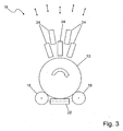
- FIG. 3 shows the test device 16 according to the invention in a schematic representation and in a second embodiment.
- the individual detectors 24 are arranged offset from one another. However, all distances 14 of the detectors 24 to the elongate object 10 are within the previously calculated detection limit.
- the staggered arrangement of the detectors 24 is then particularly advantageous to apply, if it is a particularly small diameter of the elongate object 10.
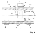
- FIG. 4 shows an embodiment of a test device 16 according to the invention with which the outer surface 10.1 and the inner surface 10.2 of a tubular elongated object 10 can be tested simultaneously or sequentially for ionizing radiation.
- one or more inner tube detectors 124 are attached to a rod 126.
- the inner tube detector 124 and the detectors 24 arranged outside the tube 10 are arranged in a plane in this embodiment.
- the inner tube detector 124 and the detectors disposed outside the tube 10 are opposed to each other. This facilitates the adjustment of the distance 14 between the detectors 24 located outside the tube 10 and the outer surface 10.1 of the tube 10 and the distance 214 between the inner tube detector 124 and the inner surface 10.2 of the tube 10.
- the inner tube detector is used 124 as the detectors 24 also movable in the radial direction.
- centering means 128 are attached in the form of a disc, which ensure that the distance 214 is maintained and that the inner tube detector 124 contacts the tube 10.
- FIG. 5 shows a block diagram with all functional units of the test apparatus 16 with their influence on each other.
- the starting point is the control device 30, which on the one hand controls the evaluation electronics 28 for the evaluation of the signals of the detectors 24, 124.
- the control device 30 controls the axial feed control 36 with the feed 22, and the radial feed control 38 with the driven rollers 18.
- the Ausnceelekttronik 28 also controls the radially acting on the elongated object 10 positioning or control 26 of the detectors 24 with the Distance 14 between detectors 24 and the object 10 is adjusted.
- the distance 124 between the inner tube detector 124 and the article 10 is controlled in an optional functional block 27, as described in the description FIG. 2 . 3 and 4 was explained.
- step 112 is followed by adjusting the propulsion 22 to move the elongated article 10 in the longitudinal direction by a predetermined length.
- the longitudinal movement is matched to the length of the measuring range formed by the arrangement of the detectors 24, so that successively the entire surface of the object 10 is detected outside and inside.
- steps 104 to 110 are repeated.
- step 116 follows. Reaching the free end of the elongate object 10 can be achieved, for example, by means of a correspondingly designed axial feed control 36 (see FIG Fig. 4 ) be determined. In step 116, the output of the detection result or the printing of release documents for the elongate object 10 takes place at the output device 34 (see FIG Fig. 4 ).
- steps 104 to 114 are repeated.
Landscapes
- Physics & Mathematics (AREA)
- Health & Medical Sciences (AREA)
- Life Sciences & Earth Sciences (AREA)
- General Physics & Mathematics (AREA)
- High Energy & Nuclear Physics (AREA)
- Molecular Biology (AREA)
- Spectroscopy & Molecular Physics (AREA)
- Measurement Of Radiation (AREA)
Applications Claiming Priority (1)
| Application Number | Priority Date | Filing Date | Title |
|---|---|---|---|
| DE102014202786.1A DE102014202786A1 (de) | 2014-02-17 | 2014-02-17 | Prüfvorrichtung und Verfahren zum Detektieren einer Oberflächenkontamination an langgestreckten Gegenständen |
Publications (2)
| Publication Number | Publication Date |
|---|---|
| EP2910976A1 true EP2910976A1 (fr) | 2015-08-26 |
| EP2910976B1 EP2910976B1 (fr) | 2019-07-24 |
Family
ID=52484364
Family Applications (1)
| Application Number | Title | Priority Date | Filing Date |
|---|---|---|---|
| EP15155422.7A Active EP2910976B1 (fr) | 2014-02-17 | 2015-02-17 | Dispositif de vérification et procédé de détection d'une contamination de surface sur des objets allongés |
Country Status (2)
| Country | Link |
|---|---|
| EP (1) | EP2910976B1 (fr) |
| DE (1) | DE102014202786A1 (fr) |
Cited By (5)
| Publication number | Priority date | Publication date | Assignee | Title |
|---|---|---|---|---|
| WO2019243495A1 (fr) * | 2018-06-22 | 2019-12-26 | Soletanche Freyssinet S.A.S. | Dispositif de détection d'un contaminant sur un mât d'échafaudage |
| CN112462407A (zh) * | 2020-11-10 | 2021-03-09 | 中国核动力研究设计院 | 一种燃料板表面污染定位检测装置和系统 |
| DE102019125975A1 (de) * | 2019-09-26 | 2021-04-01 | RWE Nuclear GmbH | Verfahren und Vorrichtung zum Messen einer radiologischen Kontamination eines Werkstückes |
| WO2022017663A1 (fr) * | 2020-07-20 | 2022-01-27 | Safetec Entsorgungs- Und Sicherheitstechnik Gmbh | Procédé de mesure de sûreté nucléaire d'un matériau à mesurer au moyen d'un système de mesure de dégagement, produit-programme informatique et système de mesure de dégagement |
| EP4524617A1 (fr) * | 2023-09-15 | 2025-03-19 | Aachen Institute for Nuclear Training GmbH | Procédé de vérification de la contrainte de rayonnement à l'intérieur de volumes internes, dispositif de mesure conçu à cet effet et produit programme informatique ainsi qu'utilisation |
Families Citing this family (1)
| Publication number | Priority date | Publication date | Assignee | Title |
|---|---|---|---|---|
| DE102023106072A1 (de) * | 2023-03-10 | 2024-09-12 | Safetec Gmbh | Messverfahren, Messsystem und Verwendung des Messsystems |
Citations (10)
| Publication number | Priority date | Publication date | Assignee | Title |
|---|---|---|---|---|
| JPS6076680A (ja) * | 1983-10-03 | 1985-05-01 | Mitsubishi Heavy Ind Ltd | 表面線量率測定装置 |
| JPH01116481A (ja) | 1987-10-30 | 1989-05-09 | Hitachi Ltd | 表面汚染モニタ |
| JPH02114192A (ja) * | 1988-10-24 | 1990-04-26 | Hitachi Plant Eng & Constr Co Ltd | 長尺物の放射線量検査装置 |
| DE3685891T2 (de) | 1985-03-08 | 1992-12-24 | Hitachi Ltd | Verfahren und vorrichtung zur messung der verteilung von radioaktivitaet. |
| US5371363A (en) * | 1993-07-26 | 1994-12-06 | Lilimpakis; Emmanuel | Device for measuring radiation within a pipe |
| US5444746A (en) * | 1990-08-20 | 1995-08-22 | Kansai Electric Power Co., Ltd. | Contamination inspecting device for portable articles |
| JP3225127B2 (ja) * | 1993-03-04 | 2001-11-05 | 株式会社東芝 | 放射性廃棄物収納容器用放射能濃度測定装置 |
| US6624425B2 (en) | 2001-05-03 | 2003-09-23 | Bio-Imaging Research, Inc. | Waste inspection tomography and non-destructive assay |
| WO2010006295A2 (fr) * | 2008-07-10 | 2010-01-14 | Innovative American Technology Inc. | Système de vérification d'un rayonnement cbrne de chariot à portique à performance élevée |
| WO2010046106A1 (fr) | 2008-10-23 | 2010-04-29 | Institut Dr. Foerster Gmbh & Co. Kg | Procédé et dispositif de contrôle d’objets longs au moyen d’une bobine |
-
2014
- 2014-02-17 DE DE102014202786.1A patent/DE102014202786A1/de not_active Ceased
-
2015
- 2015-02-17 EP EP15155422.7A patent/EP2910976B1/fr active Active
Patent Citations (10)
| Publication number | Priority date | Publication date | Assignee | Title |
|---|---|---|---|---|
| JPS6076680A (ja) * | 1983-10-03 | 1985-05-01 | Mitsubishi Heavy Ind Ltd | 表面線量率測定装置 |
| DE3685891T2 (de) | 1985-03-08 | 1992-12-24 | Hitachi Ltd | Verfahren und vorrichtung zur messung der verteilung von radioaktivitaet. |
| JPH01116481A (ja) | 1987-10-30 | 1989-05-09 | Hitachi Ltd | 表面汚染モニタ |
| JPH02114192A (ja) * | 1988-10-24 | 1990-04-26 | Hitachi Plant Eng & Constr Co Ltd | 長尺物の放射線量検査装置 |
| US5444746A (en) * | 1990-08-20 | 1995-08-22 | Kansai Electric Power Co., Ltd. | Contamination inspecting device for portable articles |
| JP3225127B2 (ja) * | 1993-03-04 | 2001-11-05 | 株式会社東芝 | 放射性廃棄物収納容器用放射能濃度測定装置 |
| US5371363A (en) * | 1993-07-26 | 1994-12-06 | Lilimpakis; Emmanuel | Device for measuring radiation within a pipe |
| US6624425B2 (en) | 2001-05-03 | 2003-09-23 | Bio-Imaging Research, Inc. | Waste inspection tomography and non-destructive assay |
| WO2010006295A2 (fr) * | 2008-07-10 | 2010-01-14 | Innovative American Technology Inc. | Système de vérification d'un rayonnement cbrne de chariot à portique à performance élevée |
| WO2010046106A1 (fr) | 2008-10-23 | 2010-04-29 | Institut Dr. Foerster Gmbh & Co. Kg | Procédé et dispositif de contrôle d’objets longs au moyen d’une bobine |
Cited By (7)
| Publication number | Priority date | Publication date | Assignee | Title |
|---|---|---|---|---|
| WO2019243495A1 (fr) * | 2018-06-22 | 2019-12-26 | Soletanche Freyssinet S.A.S. | Dispositif de détection d'un contaminant sur un mât d'échafaudage |
| JP2021528645A (ja) * | 2018-06-22 | 2021-10-21 | ソルタンシュ フレシネ ソシエテ パー アクション サンプリフィエ | 足場ポール上の汚染物質を検出するための装置 |
| US11313978B2 (en) * | 2018-06-22 | 2022-04-26 | Soletanche Freyssinet S.A.S. | Device for detecting a contaminant on a scaffolding pole |
| DE102019125975A1 (de) * | 2019-09-26 | 2021-04-01 | RWE Nuclear GmbH | Verfahren und Vorrichtung zum Messen einer radiologischen Kontamination eines Werkstückes |
| WO2022017663A1 (fr) * | 2020-07-20 | 2022-01-27 | Safetec Entsorgungs- Und Sicherheitstechnik Gmbh | Procédé de mesure de sûreté nucléaire d'un matériau à mesurer au moyen d'un système de mesure de dégagement, produit-programme informatique et système de mesure de dégagement |
| CN112462407A (zh) * | 2020-11-10 | 2021-03-09 | 中国核动力研究设计院 | 一种燃料板表面污染定位检测装置和系统 |
| EP4524617A1 (fr) * | 2023-09-15 | 2025-03-19 | Aachen Institute for Nuclear Training GmbH | Procédé de vérification de la contrainte de rayonnement à l'intérieur de volumes internes, dispositif de mesure conçu à cet effet et produit programme informatique ainsi qu'utilisation |
Also Published As
| Publication number | Publication date |
|---|---|
| DE102014202786A1 (de) | 2015-08-20 |
| EP2910976B1 (fr) | 2019-07-24 |
Similar Documents
| Publication | Publication Date | Title |
|---|---|---|
| EP2910976B1 (fr) | Dispositif de vérification et procédé de détection d'une contamination de surface sur des objets allongés | |
| EP2135030B1 (fr) | Procédé et dispositif destinés à la mesure optique de filets extérieurs | |
| EP2252855B1 (fr) | Procédé et dispositif de détermination de la position et de l'orientation d'un échantillon | |
| DE2930407A1 (de) | Geraet zur untersuchung von rohren in einer anlage | |
| EP2660557A1 (fr) | Dispositif et procédé de mesure 3D d'un tuyau | |
| EP2699364B1 (fr) | Procédé et dispositif permettant de déterminer l'épaisseur d'un produit laminé | |
| DE102012100639B4 (de) | Härteprüfgerät und Verfahren zum Einstellen eines Härteprüfgerätes | |
| EP2737852A1 (fr) | Procédé de détection des propriétés d'imagerie géométriques d'un détecteur à panneau plat, systèm de test adapté suivant et corps de calibrage | |
| DE102014110548A1 (de) | Roboterarmsystem und Verfahren zum Kalibrieren einer Parallelität | |
| WO2014202340A1 (fr) | Dispositif et procédé permettant de déterminer le poids en particulier d'un contenant rempli de produit | |
| EP3225971A1 (fr) | Dispositif et procédé de détermination d'une concentration d'au moins une matière dans un milieu liquide | |
| DE102013009245B4 (de) | Rohrgeometrieermittlungsverfahren | |
| DE69005586T2 (de) | Vorrichtung zur Messung der Strahlungsverseuchung von grossen Objekten. | |
| DE69027538T2 (de) | Verfahren zum messen von defekten in einer pipeline | |
| WO2002033347A2 (fr) | Procede permettant de determiner l'alignement d'un corps cylindrique par rapport a une direction de reference | |
| DE10162703A1 (de) | Verfahren und Vorrichtung zur Fehlerausblendung und -Kompensation von durch Gammagraphie hervorgerufenen Störsignalen bei radiometrischen Meßsystemen | |
| DE102012204498A1 (de) | Kanalrohrinspektionsvorrichtung und Verfahren zum Inspizieren von Kanalrohren | |
| EP1092947A2 (fr) | Procédé pour la détection de l' alignement d' un corps cylindrique par rapport à une direction de référence | |
| EP3737935B1 (fr) | Plateforme de cibles pour le traitement de cibles irradiées provenant d'un réacteur nucléaire | |
| DE102010033923B4 (de) | Vorrichtung zum Aufbringen mechanischer Belastungen auf einen Prüfkörper in tomografischen Messungen | |
| DE19843397C1 (de) | Computertomographisches Verfahren und Computertomograph zur Prüfung eine Gegenstandes | |
| DE3546480C2 (de) | Meßeinrichtung für die Wickelhärte eines Wickels | |
| DE4000878C2 (de) | Verfahren zum Prüfen der Koaxialitätsabweichung zwischen einer Meßstelle und einer Bezugsstelle an einem zu prüfenden Gewindeteil, insbesondere Schraube | |
| DE19827364A1 (de) | Verfahren und Vorrichtung zum Messen kegeliger Gewinde | |
| DE102015220002B4 (de) | Verfahren zur kontinuierlichen Vermessung von Außenkonturen sowie Messvorrichtung zur Durchführung des Verfahrens |
Legal Events
| Date | Code | Title | Description |
|---|---|---|---|
| PUAI | Public reference made under article 153(3) epc to a published international application that has entered the european phase |
Free format text: ORIGINAL CODE: 0009012 |
|
| AK | Designated contracting states |
Kind code of ref document: A1 Designated state(s): AL AT BE BG CH CY CZ DE DK EE ES FI FR GB GR HR HU IE IS IT LI LT LU LV MC MK MT NL NO PL PT RO RS SE SI SK SM TR |
|
| AX | Request for extension of the european patent |
Extension state: BA ME |
|
| RAP1 | Party data changed (applicant data changed or rights of an application transferred) |
Owner name: ENBW ENERGIE BADEN-WUERTTEMBERG AG |
|
| 17P | Request for examination filed |
Effective date: 20160226 |
|
| RBV | Designated contracting states (corrected) |
Designated state(s): AL AT BE BG CH CY CZ DE DK EE ES FI FR GB GR HR HU IE IS IT LI LT LU LV MC MK MT NL NO PL PT RO RS SE SI SK SM TR |
|
| STAA | Information on the status of an ep patent application or granted ep patent |
Free format text: STATUS: EXAMINATION IS IN PROGRESS |
|
| 17Q | First examination report despatched |
Effective date: 20181017 |
|
| GRAP | Despatch of communication of intention to grant a patent |
Free format text: ORIGINAL CODE: EPIDOSNIGR1 |
|
| STAA | Information on the status of an ep patent application or granted ep patent |
Free format text: STATUS: GRANT OF PATENT IS INTENDED |
|
| INTG | Intention to grant announced |
Effective date: 20190208 |
|
| GRAS | Grant fee paid |
Free format text: ORIGINAL CODE: EPIDOSNIGR3 |
|
| GRAA | (expected) grant |
Free format text: ORIGINAL CODE: 0009210 |
|
| STAA | Information on the status of an ep patent application or granted ep patent |
Free format text: STATUS: THE PATENT HAS BEEN GRANTED |
|
| AK | Designated contracting states |
Kind code of ref document: B1 Designated state(s): AL AT BE BG CH CY CZ DE DK EE ES FI FR GB GR HR HU IE IS IT LI LT LU LV MC MK MT NL NO PL PT RO RS SE SI SK SM TR |
|
| REG | Reference to a national code |
Ref country code: GB Ref legal event code: FG4D Free format text: NOT ENGLISH |
|
| REG | Reference to a national code |
Ref country code: CH Ref legal event code: EP |
|
| REG | Reference to a national code |
Ref country code: DE Ref legal event code: R096 Ref document number: 502015009712 Country of ref document: DE |
|
| REG | Reference to a national code |
Ref country code: AT Ref legal event code: REF Ref document number: 1158846 Country of ref document: AT Kind code of ref document: T Effective date: 20190815 |
|
| REG | Reference to a national code |
Ref country code: IE Ref legal event code: FG4D Free format text: LANGUAGE OF EP DOCUMENT: GERMAN |
|
| REG | Reference to a national code |
Ref country code: CH Ref legal event code: NV Representative=s name: DREISS PATENTANWAELTE PARTG MBB, DE |
|
| REG | Reference to a national code |
Ref country code: NL Ref legal event code: MP Effective date: 20190724 |
|
| REG | Reference to a national code |
Ref country code: LT Ref legal event code: MG4D |
|
| PG25 | Lapsed in a contracting state [announced via postgrant information from national office to epo] |
Ref country code: BG Free format text: LAPSE BECAUSE OF FAILURE TO SUBMIT A TRANSLATION OF THE DESCRIPTION OR TO PAY THE FEE WITHIN THE PRESCRIBED TIME-LIMIT Effective date: 20191024 Ref country code: NL Free format text: LAPSE BECAUSE OF FAILURE TO SUBMIT A TRANSLATION OF THE DESCRIPTION OR TO PAY THE FEE WITHIN THE PRESCRIBED TIME-LIMIT Effective date: 20190724 Ref country code: PT Free format text: LAPSE BECAUSE OF FAILURE TO SUBMIT A TRANSLATION OF THE DESCRIPTION OR TO PAY THE FEE WITHIN THE PRESCRIBED TIME-LIMIT Effective date: 20191125 Ref country code: HR Free format text: LAPSE BECAUSE OF FAILURE TO SUBMIT A TRANSLATION OF THE DESCRIPTION OR TO PAY THE FEE WITHIN THE PRESCRIBED TIME-LIMIT Effective date: 20190724 Ref country code: NO Free format text: LAPSE BECAUSE OF FAILURE TO SUBMIT A TRANSLATION OF THE DESCRIPTION OR TO PAY THE FEE WITHIN THE PRESCRIBED TIME-LIMIT Effective date: 20191024 Ref country code: LT Free format text: LAPSE BECAUSE OF FAILURE TO SUBMIT A TRANSLATION OF THE DESCRIPTION OR TO PAY THE FEE WITHIN THE PRESCRIBED TIME-LIMIT Effective date: 20190724 Ref country code: FI Free format text: LAPSE BECAUSE OF FAILURE TO SUBMIT A TRANSLATION OF THE DESCRIPTION OR TO PAY THE FEE WITHIN THE PRESCRIBED TIME-LIMIT Effective date: 20190724 Ref country code: SE Free format text: LAPSE BECAUSE OF FAILURE TO SUBMIT A TRANSLATION OF THE DESCRIPTION OR TO PAY THE FEE WITHIN THE PRESCRIBED TIME-LIMIT Effective date: 20190724 |
|
| PG25 | Lapsed in a contracting state [announced via postgrant information from national office to epo] |
Ref country code: IS Free format text: LAPSE BECAUSE OF FAILURE TO SUBMIT A TRANSLATION OF THE DESCRIPTION OR TO PAY THE FEE WITHIN THE PRESCRIBED TIME-LIMIT Effective date: 20191124 Ref country code: LV Free format text: LAPSE BECAUSE OF FAILURE TO SUBMIT A TRANSLATION OF THE DESCRIPTION OR TO PAY THE FEE WITHIN THE PRESCRIBED TIME-LIMIT Effective date: 20190724 Ref country code: GR Free format text: LAPSE BECAUSE OF FAILURE TO SUBMIT A TRANSLATION OF THE DESCRIPTION OR TO PAY THE FEE WITHIN THE PRESCRIBED TIME-LIMIT Effective date: 20191025 Ref country code: RS Free format text: LAPSE BECAUSE OF FAILURE TO SUBMIT A TRANSLATION OF THE DESCRIPTION OR TO PAY THE FEE WITHIN THE PRESCRIBED TIME-LIMIT Effective date: 20190724 Ref country code: AL Free format text: LAPSE BECAUSE OF FAILURE TO SUBMIT A TRANSLATION OF THE DESCRIPTION OR TO PAY THE FEE WITHIN THE PRESCRIBED TIME-LIMIT Effective date: 20190724 Ref country code: ES Free format text: LAPSE BECAUSE OF FAILURE TO SUBMIT A TRANSLATION OF THE DESCRIPTION OR TO PAY THE FEE WITHIN THE PRESCRIBED TIME-LIMIT Effective date: 20190724 |
|
| PG25 | Lapsed in a contracting state [announced via postgrant information from national office to epo] |
Ref country code: TR Free format text: LAPSE BECAUSE OF FAILURE TO SUBMIT A TRANSLATION OF THE DESCRIPTION OR TO PAY THE FEE WITHIN THE PRESCRIBED TIME-LIMIT Effective date: 20190724 |
|
| PG25 | Lapsed in a contracting state [announced via postgrant information from national office to epo] |
Ref country code: RO Free format text: LAPSE BECAUSE OF FAILURE TO SUBMIT A TRANSLATION OF THE DESCRIPTION OR TO PAY THE FEE WITHIN THE PRESCRIBED TIME-LIMIT Effective date: 20190724 Ref country code: IT Free format text: LAPSE BECAUSE OF FAILURE TO SUBMIT A TRANSLATION OF THE DESCRIPTION OR TO PAY THE FEE WITHIN THE PRESCRIBED TIME-LIMIT Effective date: 20190724 Ref country code: EE Free format text: LAPSE BECAUSE OF FAILURE TO SUBMIT A TRANSLATION OF THE DESCRIPTION OR TO PAY THE FEE WITHIN THE PRESCRIBED TIME-LIMIT Effective date: 20190724 Ref country code: DK Free format text: LAPSE BECAUSE OF FAILURE TO SUBMIT A TRANSLATION OF THE DESCRIPTION OR TO PAY THE FEE WITHIN THE PRESCRIBED TIME-LIMIT Effective date: 20190724 Ref country code: PL Free format text: LAPSE BECAUSE OF FAILURE TO SUBMIT A TRANSLATION OF THE DESCRIPTION OR TO PAY THE FEE WITHIN THE PRESCRIBED TIME-LIMIT Effective date: 20190724 |
|
| PG25 | Lapsed in a contracting state [announced via postgrant information from national office to epo] |
Ref country code: SK Free format text: LAPSE BECAUSE OF FAILURE TO SUBMIT A TRANSLATION OF THE DESCRIPTION OR TO PAY THE FEE WITHIN THE PRESCRIBED TIME-LIMIT Effective date: 20190724 Ref country code: CZ Free format text: LAPSE BECAUSE OF FAILURE TO SUBMIT A TRANSLATION OF THE DESCRIPTION OR TO PAY THE FEE WITHIN THE PRESCRIBED TIME-LIMIT Effective date: 20190724 Ref country code: IS Free format text: LAPSE BECAUSE OF FAILURE TO SUBMIT A TRANSLATION OF THE DESCRIPTION OR TO PAY THE FEE WITHIN THE PRESCRIBED TIME-LIMIT Effective date: 20200224 Ref country code: SM Free format text: LAPSE BECAUSE OF FAILURE TO SUBMIT A TRANSLATION OF THE DESCRIPTION OR TO PAY THE FEE WITHIN THE PRESCRIBED TIME-LIMIT Effective date: 20190724 |
|
| REG | Reference to a national code |
Ref country code: DE Ref legal event code: R097 Ref document number: 502015009712 Country of ref document: DE |
|
| PLBE | No opposition filed within time limit |
Free format text: ORIGINAL CODE: 0009261 |
|
| STAA | Information on the status of an ep patent application or granted ep patent |
Free format text: STATUS: NO OPPOSITION FILED WITHIN TIME LIMIT |
|
| PG2D | Information on lapse in contracting state deleted |
Ref country code: IS |
|
| 26N | No opposition filed |
Effective date: 20200603 |
|
| PG25 | Lapsed in a contracting state [announced via postgrant information from national office to epo] |
Ref country code: SI Free format text: LAPSE BECAUSE OF FAILURE TO SUBMIT A TRANSLATION OF THE DESCRIPTION OR TO PAY THE FEE WITHIN THE PRESCRIBED TIME-LIMIT Effective date: 20190724 |
|
| REG | Reference to a national code |
Ref country code: BE Ref legal event code: MM Effective date: 20200229 |
|
| PG25 | Lapsed in a contracting state [announced via postgrant information from national office to epo] |
Ref country code: MC Free format text: LAPSE BECAUSE OF FAILURE TO SUBMIT A TRANSLATION OF THE DESCRIPTION OR TO PAY THE FEE WITHIN THE PRESCRIBED TIME-LIMIT Effective date: 20190724 Ref country code: LU Free format text: LAPSE BECAUSE OF NON-PAYMENT OF DUE FEES Effective date: 20200217 |
|
| PG25 | Lapsed in a contracting state [announced via postgrant information from national office to epo] |
Ref country code: IE Free format text: LAPSE BECAUSE OF NON-PAYMENT OF DUE FEES Effective date: 20200217 |
|
| PG25 | Lapsed in a contracting state [announced via postgrant information from national office to epo] |
Ref country code: BE Free format text: LAPSE BECAUSE OF NON-PAYMENT OF DUE FEES Effective date: 20200229 |
|
| REG | Reference to a national code |
Ref country code: AT Ref legal event code: MM01 Ref document number: 1158846 Country of ref document: AT Kind code of ref document: T Effective date: 20200217 |
|
| PG25 | Lapsed in a contracting state [announced via postgrant information from national office to epo] |
Ref country code: AT Free format text: LAPSE BECAUSE OF NON-PAYMENT OF DUE FEES Effective date: 20200217 |
|
| PG25 | Lapsed in a contracting state [announced via postgrant information from national office to epo] |
Ref country code: MT Free format text: LAPSE BECAUSE OF FAILURE TO SUBMIT A TRANSLATION OF THE DESCRIPTION OR TO PAY THE FEE WITHIN THE PRESCRIBED TIME-LIMIT Effective date: 20190724 Ref country code: CY Free format text: LAPSE BECAUSE OF FAILURE TO SUBMIT A TRANSLATION OF THE DESCRIPTION OR TO PAY THE FEE WITHIN THE PRESCRIBED TIME-LIMIT Effective date: 20190724 |
|
| PG25 | Lapsed in a contracting state [announced via postgrant information from national office to epo] |
Ref country code: MK Free format text: LAPSE BECAUSE OF FAILURE TO SUBMIT A TRANSLATION OF THE DESCRIPTION OR TO PAY THE FEE WITHIN THE PRESCRIBED TIME-LIMIT Effective date: 20190724 |
|
| P01 | Opt-out of the competence of the unified patent court (upc) registered |
Effective date: 20230809 |
|
| PGFP | Annual fee paid to national office [announced via postgrant information from national office to epo] |
Ref country code: CH Payment date: 20240301 Year of fee payment: 10 Ref country code: GB Payment date: 20240213 Year of fee payment: 10 |
|
| PGFP | Annual fee paid to national office [announced via postgrant information from national office to epo] |
Ref country code: FR Payment date: 20240222 Year of fee payment: 10 |
|
| PGFP | Annual fee paid to national office [announced via postgrant information from national office to epo] |
Ref country code: DE Payment date: 20240415 Year of fee payment: 10 |
|
| REG | Reference to a national code |
Ref country code: DE Ref legal event code: R119 Ref document number: 502015009712 Country of ref document: DE |
|
| REG | Reference to a national code |
Ref country code: CH Ref legal event code: PL |
|
| PG25 | Lapsed in a contracting state [announced via postgrant information from national office to epo] |
Ref country code: CH Free format text: LAPSE BECAUSE OF NON-PAYMENT OF DUE FEES Effective date: 20250228 |
|
| GBPC | Gb: european patent ceased through non-payment of renewal fee |
Effective date: 20250217 |
|
| PG25 | Lapsed in a contracting state [announced via postgrant information from national office to epo] |
Ref country code: DE Free format text: LAPSE BECAUSE OF NON-PAYMENT OF DUE FEES Effective date: 20250902 |
|
| PG25 | Lapsed in a contracting state [announced via postgrant information from national office to epo] |
Ref country code: GB Free format text: LAPSE BECAUSE OF NON-PAYMENT OF DUE FEES Effective date: 20250217 |
|
| PG25 | Lapsed in a contracting state [announced via postgrant information from national office to epo] |
Ref country code: FR Free format text: LAPSE BECAUSE OF NON-PAYMENT OF DUE FEES Effective date: 20250228 |