EP2910977B1 - Verfahren zur Überwachung einer Stromversorgungsleitung in einem seismischen Kabel, entsprechendes System, Computerprogrammprodukt und nicht transitorisches computerlesbares Trägermedium - Google Patents
Verfahren zur Überwachung einer Stromversorgungsleitung in einem seismischen Kabel, entsprechendes System, Computerprogrammprodukt und nicht transitorisches computerlesbares Trägermedium Download PDFInfo
- Publication number
- EP2910977B1 EP2910977B1 EP14305240.5A EP14305240A EP2910977B1 EP 2910977 B1 EP2910977 B1 EP 2910977B1 EP 14305240 A EP14305240 A EP 14305240A EP 2910977 B1 EP2910977 B1 EP 2910977B1
- Authority
- EP
- European Patent Office
- Prior art keywords
- optical
- cable
- master
- seismic
- power supply
- Prior art date
- Legal status (The legal status is an assumption and is not a legal conclusion. Google has not performed a legal analysis and makes no representation as to the accuracy of the status listed.)
- Not-in-force
Links
Images

Classifications
-
- G—PHYSICS
- G01—MEASURING; TESTING
- G01R—MEASURING ELECTRIC VARIABLES; MEASURING MAGNETIC VARIABLES
- G01R31/00—Arrangements for testing electric properties; Arrangements for locating electric faults; Arrangements for electrical testing characterised by what is being tested not provided for elsewhere
- G01R31/50—Testing of electric apparatus, lines, cables or components for short-circuits, continuity, leakage current or incorrect line connections
- G01R31/58—Testing of lines, cables or conductors
-
- G—PHYSICS
- G01—MEASURING; TESTING
- G01V—GEOPHYSICS; GRAVITATIONAL MEASUREMENTS; DETECTING MASSES OR OBJECTS; TAGS
- G01V1/00—Seismology; Seismic or acoustic prospecting or detecting
- G01V1/16—Receiving elements for seismic signals; Arrangements or adaptations of receiving elements
- G01V1/20—Arrangements of receiving elements, e.g. geophone pattern
- G01V1/201—Constructional details of seismic cables, e.g. streamers
-
- G—PHYSICS
- G01—MEASURING; TESTING
- G01M—TESTING STATIC OR DYNAMIC BALANCE OF MACHINES OR STRUCTURES; TESTING OF STRUCTURES OR APPARATUS, NOT OTHERWISE PROVIDED FOR
- G01M11/00—Testing of optical apparatus; Testing structures by optical methods not otherwise provided for
- G01M11/08—Testing mechanical properties
- G01M11/083—Testing mechanical properties by using an optical fiber in contact with the device under test [DUT]
-
- G—PHYSICS
- G01—MEASURING; TESTING
- G01R—MEASURING ELECTRIC VARIABLES; MEASURING MAGNETIC VARIABLES
- G01R15/00—Details of measuring arrangements of the types provided for in groups G01R17/00 - G01R29/00, G01R33/00 - G01R33/26 or G01R35/00
- G01R15/14—Adaptations providing voltage or current isolation, e.g. for high-voltage or high-current networks
- G01R15/24—Adaptations providing voltage or current isolation, e.g. for high-voltage or high-current networks using light-modulating devices
-
- G—PHYSICS
- G01—MEASURING; TESTING
- G01R—MEASURING ELECTRIC VARIABLES; MEASURING MAGNETIC VARIABLES
- G01R31/00—Arrangements for testing electric properties; Arrangements for locating electric faults; Arrangements for electrical testing characterised by what is being tested not provided for elsewhere
- G01R31/08—Locating faults in cables, transmission lines, or networks
- G01R31/081—Locating faults in cables, transmission lines, or networks according to type of conductors
- G01R31/083—Locating faults in cables, transmission lines, or networks according to type of conductors in cables, e.g. underground
-
- G—PHYSICS
- G01—MEASURING; TESTING
- G01V—GEOPHYSICS; GRAVITATIONAL MEASUREMENTS; DETECTING MASSES OR OBJECTS; TAGS
- G01V1/00—Seismology; Seismic or acoustic prospecting or detecting
- G01V1/16—Receiving elements for seismic signals; Arrangements or adaptations of receiving elements
- G01V1/18—Receiving elements, e.g. seismometer, geophone or torque detectors, for localised single point measurements
-
- G—PHYSICS
- G01—MEASURING; TESTING
- G01V—GEOPHYSICS; GRAVITATIONAL MEASUREMENTS; DETECTING MASSES OR OBJECTS; TAGS
- G01V1/00—Seismology; Seismic or acoustic prospecting or detecting
- G01V1/38—Seismology; Seismic or acoustic prospecting or detecting specially adapted for water-covered areas
Definitions
- the field of the invention is that of equipments for the seismic prospection, and more particularly seismic cables designed for hydrocarbon exploration.
- the invention pertains to a technique for monitoring an electrical power supply line comprised in a seismic cable.
- the present invention can be applied notably, but not exclusively, to marine seismic prospection.
- the operations of acquiring seismic data on site conventionally use networks of sensors distributed along cables in order to form linear acoustic antennas, also referred to as “streamers” or “seismic streamers” or “seismic cables”.
- the seismic streamers are towed through water behind a seismic vessel at a water depth that can be more or less deep.
- a seismic cable is understood to be a seismic streamer which can be maintained at a selected depth under the sea surface or a cable lying on the sea bed, for example in an Ocean Bottom configuration, also known as Ocean Bottom Cable (OBC) for seabed acquisition.
- OBC Ocean Bottom Cable
- a c marine seismic method is usually based on analysis of reflected seismic waves.
- one or more submerged seismic sources are activated in order to propagate seismic wave trains.
- the pressure wave generated by the seismic source passes through the column of water and insonifies the different layers of the sea bed.
- Part of the seismic waves (i.e. acoustic signals) reflected are then detected by the sensors (e.g. hydrophones, geophones, accelerometers or the like) distributed over the length of the seismic cables.
- the sensors e.g. hydrophones, geophones, accelerometers or the like
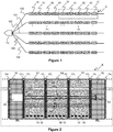
- a seismic cable 100 generally comprises a plurality of controllers 20, such as telemetry modules, arranged along the seismic cable 100. Part of cable comprised between two controllers 20 forms a portion of cable. Each portion of cable is itself divided into a plurality of cable sections comprising each a plurality of seismic sensors, such as hydrophones or geophones or accelerometers, arranged along the section and adapted for detecting acoustic signals.
- the seismic cable 100 shown in figure 1 comprises, for example, two portions of cable P1 and P2 each comprising three cable sections S1 to S3 comprising seismic sensors for data acquisition.
- the seismic sensors are referenced 10 in figure 2 , which illustrates in detail the block referenced A in figure 1 , i.e. a portion P2 of the seismic cable referenced 100.
- Each cable section S1 to S3 may further comprise a plurality of nodes (not shown on the figures) distributed along the cable at intervals that are not necessarily regular.
- nodes are connected to the controllers via electrical wires (not shown on figures). More precisely, all the nodes are provided serially along the electrical wires from the head end of the seismic cable until the tail end of the seismic cable, with the controllers being distributed between groups of nodes on the electrical wires.
- a node is adapted for collecting seismic data issued from a given associated set of sensors 10 and to digitize them before sending them, via the controllers 20, to the central unit situated on the seismic vessel.
- Controllers are assembled in series along the seismic cable and each associated with at least one of the nodes, each controller providing power supply and synchronization of the nodes wherewith it is associated. More precisely, the controllers concentrate the data issued from a plurality of nodes. Then, the controllers direct the concentrated data received from the nodes and the sensors upon data transmission lines (such as telemetry line 40) for carrying data from or towards the controllers 20, and to route said data towards the recorder vessel 115.
- data transmission lines such as telemetry line 40
- Each node is made up of four basic components:
- Sensing units are usually composed of two subunits: sensors and analog-to-digital converters (ADCs).
- ADCs analog-to-digital converters
- the analog signals produced by the sensors based on the observed phenomenon are converted to digital signals by the ADC, and then fed into the processing unit.
- the processing unit which is generally associated with a small storage unit for buffering, manages the procedures that make the nodes collaborate with the other nodes to carry out the assigned sensing tasks.
- a transceiver unit connects the node to the network.
- each node performs the analog to digital conversion of the signal from sensors. If sensors are digital (sensors are micro-machined accelerometer for example), no conversion is performed by the corresponding node. Then, these data are sent to a central data processing unit onboard the recorder vessel 115 via the network of data transmission lines. More precisely, each node has the capabilities to collect data and route data back to a controller 20. The data are conventionally sent from the nodes to the central processing unit via controllers 20.
- Each controller performs different functions, including:
- the nodes and controllers are thus devised to only perform signal processing functions. In other words, the nodes and controllers progressively return the seismic data to the central processing unit.
- the power supplying lines supply the controllers and the sensors with a high voltage (such as a voltage about 300V-1000V), so as to limit the level of current in said power supplying lines.
- a high voltage such as a voltage about 300V-1000V
- a module of each controller converts the High Voltage received from a power supplying line to a Low Voltage to power the seismic sensors bi-directionally via the power lines.
- the controllers also retrieve and process data from the seismic sensors connected on each side, via electrical wires, and operate interface between the sensors and the data transmission lines 40 by directing the data received from the sensors on the data transmission lines 40.
- each cable section S1 to S3 has a connector on each of its ends, namely: connectors O1 1 , O1 2 for the section S1, connectors O2 1 , O2 2 for the section S2 and connectors O3 1 , O3 2 for the section S3.
- Each controller 20 1 and 20 2 has a connector on each of its ends, namely: connectors Om 1 , Om 2 for the controller 20 1 and connectors Os 1 , Os 2 for the controller 20 2 .
- a connector of a given section is adapted to connect a connector of a section adjacent to said given section, or a connector of a controller adjacent to said given section, so as to allow an electrical and/or optical interconnection when connected.
- Figure 2 illustrates the configuration of a common seismic cable which comprises:
- the data transmission line 40 is generally consisted of a set of electrical copper wires for carrying electrical signals and/or a set of optical fibers for carrying optical signals from or towards the controllers 20.
- the data conveyed by the transmission line 40 belongs to the group comprising: seismic data issued from sensors 10 and control data issued from nodes (for example results of tests on sensors), control data issued from a master controller to a slave controller and/or from a slave controller to a master controller (for example leakage of a controller, overconsumption of a controller).
- the electrical power supply line 50 is adapted for supplying in cascade pairs of master and slave controllers 20 on portions of the electrical power supply line 50.
- a master controller of a pair of master and slave controllers is responsible for monitoring the portion of electrical power supply line comprised between this pair of master and slave controllers.
- the master controller 20 1 is responsible for managing the electrical power supply to the slave controller 20 2 .
- the master controller 20 1 also monitors the electrical power supply of nodes arranged along the cable portion P2.
- the master controller manages the power supply to the slave controller which can be placed before (i.e. vessel side, as illustrated on figure 2 ) or after (i.e. seismic cable end side), and not necessary immediately adjacent to the master controller.
- the slave controller 20 2 is placed immediately adjacent to the master controller 20 1 , so that the power supply is carried out for two immediate successive master and slave controllers. This is, of course, a particular embodiment of implementation.
- the controllers are supplied with high voltage from the seismic vessel (typically comprised between 300 and 900 V) via the electrical power supply line 50, which poses problems of safety.
- each portion of seismic cable 100 comprised between a master controller 20 1 and the slave controller 20 2 is equipped with a safety loop that allows to stop the high voltage supply if necessary.
- the safety loop SL is composed of a pair of two electrical copper wires 61, 62 comprised between the master 20 1 and slave 20 2 controllers.
- the pair of electrical copper wires 61 and 62 are connected via an impedance element 63, of specific impedance value, which is comprised in the slave controller 20 2 .
- a measurement unit 64 placed within the master controller 20 1 is adapted for performing an impedance measurement.
- the master controller 20 1 can propagates (or continues to propagate) the high voltage to the slave controller 20 2 via the portion of the electrical power supply line 50 comprised between these two controllers.
- the master controller 20 1 must stop (or not launch) the electrical supply sent to the slave controller 20 2 to allow interventions (seismic cable retrieving, fault or damage location, change of deficient portion or elements of the cable, etc.).
- WO2007111389 discloses a power cable capable of detecting failure, that includes a conductor, and an auxiliary line which is inserted into an inner layer provided between the conductor and an outermost layer and is installed to extend in a longitudinal direction in a spiral arrangement.
- Document GB2437840 deals with an array of seismic sensor stations that comprises a plurality of array cables each comprising a series of array cable modules and a multi-fibre lead cable.
- Each array cable module comprises a series of seismic sensor stations connected by the lead cable.
- Each sensor station houses a plurality of optical sensors, and all stations within the same array cable module share a common sensor fibre.
- the invention in at least one embodiment, is aimed especially at overcoming these different drawbacks of the prior art.
- a particular embodiment of the invention proposes a method for monitoring an electrical power supply line comprised in a seismic cable, according to claim 1.
- the method is characterized in that, for at least one given pair of master and slave controllers, the master controller performs a step of monitoring a portion of said electrical power supply line comprised between said master and slave controllers, by using an optical loop established on a portion of said optical transmission line comprised between said master and slave controllers.
- the optical loop starts from the master controller and passes through the slave controller.
- the invention thus allows, in taking advantage of the optical architecture present within the seismic cable, to implement a purely optical monitoring of the electrical power supply line.
- the invention relies on the astute using of the optical transmission line usually used for conveying optical signals, to implement a new function consisting in verifying the proper functioning of the electrical power supply line.
- an optical loop is established on the optical transmission line portion comprised between a pair of master and slave controllers, to check the proper functioning of the electrical supply line portion comprised between said pair of controllers and thereby avoiding any possible accidental exposure to high voltage in the event of opening of the electrical supply line.
- the monitoring system according to the invention does not require any conventional electrical loop to ensure the electrical power supply line monitoring. This therefore enables to reduce the streamer weight and offers a cost-effective seismic cable.
- the master controller manages the power supply to the to the slave controller which can be placed before or after the master controller, and adjacent or not to the master controller.
- the principle of the invention thus relies on the measurement, by the master controller, of reflection of an optical signal on the slave controller in order to ensure that the electrical supply line is not open.
- the principle is aimed at verifying the seismic cable is not open by verifying the optical transmission line portion comprised between two controllers is not open.
- the master controller further performs:
- This first piece of monitoring information can be thus used for detecting default on the electrical power supply line:
- said at least one given pair of master and slave controllers being separated by a cable portion comprising a plurality of cable sections, each cable section having an optical connector on both ends of said cable section, the master controller further performs, if the effective propagation duration is different from the first reference propagation duration:
- This second piece of monitoring information makes it possible to detect a failure location of the electrical power supply line.
- the method according to the invention enables to know in which cable section of the cable portion the failure occurred. This makes the intervention and maintenance times on the electrical power supply line much easier and faster. This relies on the use of the presence of optical connectors along the seismic cable, to establish an optical sub-loop starting from the master controller and passing through the last connector on which the signal is reflected, which provides useful additional information on the location of a failure detected on the seismic cable.
- the master controller further performs the steps of:
- a local processing of monitoring information can be thus carried out at the slave controller level to take a decision to stop supplying the slave controller of said electrical power supply line portion.
- the master controller further performs a step of sending said first second piece of monitoring information and/or said second piece of monitoring information to a remote control system, accompanied with an identifier of said master controller, so as to take a positive or negative decision to stop supplying on said electrical power supply line.
- the processing of monitoring information can be carried out at a remote location, for example by a control system placed on-board a vessel (towing the seismic cable), to take a decision to stop supplying the electrical power supply line.
- the identifier enables the control system to identify the master controller concerned and thus the portion of electrical power supply line concerned.
- the invention pertains to a system for monitoring an electrical power supply line comprised in a seismic cable and extending along said seismic cable, according to claim 6.
- this particular embodiment relies on a wholly novel and inventive approach taking advantage of the optical transmission line usually used for conveying optical signals, to implement an optical loop enabling to check the proper functioning of the electrical power supply line.
- the principle of the invention indeed consists in verifying the seismic cable is not open by verifying the optical transmission line portion comprised between two controllers is not open.
- the monitoring system according to the invention does not require any dedicated electrical monitoring loop to ensure the electrical power supply line monitoring. This enables a simple and cost-effective implementation of the monitoring system.
- the optical loop aims at verifying the seismic cable is not open by verifying the optical transmission line portion comprised between two controllers is not open.
- the principle is based on the measurement, by the master controller, of reflection of an optical signal on the slave controller in order to ensure that the electrical supply line is not open.
- said means for monitoring comprise means for processing the optical return signal received by the optical sensor.
- said light signal reflecting means comprise a device having a return loss coefficient which is upper than -15dB.
- said light signal reflecting means comprise a device belonging to the following group:
- the reflective mirror can be obtained by means of an optical fiber whose end is polished to act as mirror reflecting the optical signal from the optical source through an angle of approximately 180 degrees along the axis of the fiber. More broadly, the light signal reflecting means can be any device that comprises an at least partially reflective surface.
- said at least one given pair of master and slave controllers are separated by a cable portion comprising a plurality of cable sections, each cable section comprising an optical connector on both ends of said cable section having a return loss coefficient which is upper than -15dB when disconnected.
- an optical connector disconnected is detected as a function of its return loss coefficient, which enables to easily locate which cable section is defective.
- each optical connector is a right-cleaved physical contact optical connector.
- This kind of connectors costs little.
- a right-cleaved physical contact means that the contact area of each connector coupled is polished without angle.
- the seismic cable belongs to the group comprising:
- the invention pertains to a computer program product according to claim 13.
- the invention pertains to a non-transitory computer-readable carrier medium, storing a program which, when executed by a computer or a processor causes the computer or the processor to carry out the above-mentioned method (in any of its different embodiments).
- the invention relies on the use of a safety optical loop to carry out the monitoring of an electrical power supply line within a seismic cable.
- the seismic cable according to the invention comprises:
- the electrical transmission line typically comprises at least one pair of copper wires. It conveys electrical data comprising notably, but not exclusively, seismic data and test data between the controllers and nodes.
- the electrical transmission line is further used for powering the nodes arranged on the cable with a low voltage power.
- the optical transmission line typically comprises one or several optical fibers which convey optical data comprising notably, but not exclusively, seismic data and control data from master controller to slave controller and/or from slave controller to master controller.
- the optical transmission line typically cooperates with an optical light source (hereafter referenced as "Tx”) comprised in the master controller and with an optical light receiver (hereafter referenced as “Rx”) comprised in the slave controller, used respectively for optical data transmission and reception.
- Tx optical light source
- Rx optical light receiver
- FIG 3 illustrates a particular embodiment of the monitoring system according to the invention, implemented in a portion 220 of a seismic cable, for example the seismic cable 100 illustrated on Figure 1 .
- the seismic cable portion 220 is comprised between a master controller C 1 and a slave controller C 2 , the master controller C 1 managing the power supply of the slave controller C 2 .
- the seismic cable portion 220 is divided into a set of successive cable sections dedicated to data acquisition, referenced S 10 , S 20 , S 30 , ... S p .
- Each cable section may comprise a plurality of nodes (not shown on the figures) distributed along the cable at intervals that are not necessarily regular.
- a node is adapted for collecting seismic data issued from a given associated set of sensors 210 and to digitize them before sending them, via the controllers, to the central unit situated on the seismic vessel.
- the seismic sensors 210 such as hydrophones or geophones or accelerometers, are arranged along the section and are adapted for detecting acoustic signals.
- Each cable section comprises an optical connector on both ends, adapted for allowing a mechanical and optical interconnection with another cable section or with a controller.
- the cable section S 10 has the optical connectors O10 1 , O10 2 .
- the cable section S 20 has the optical connectors O20 1 , O20 2 .
- the cable section S 30 has the optical connectors O30 1 , O30 2 .
- the cable section S P has the optical connectors OP 1 , OP 2 .
- the master controller C 1 has a connector on each of its ends, namely the connectors OM 1 , OM 2 .
- the slave controller C 2 has a connector on each of its ends, namely the connectors OS 1 , OS 2 .
- the connector OM 2 is adapted to mat with the connector O10 1 of the first section S 10 of the cable portion 220, whereas the connector OM 1 is adapted to mat with a connector of a section of another cable portion not shown on the figure.
- the connector OS 1 is adapted to mat with the connector Op 2 of the last section S p of the cable portion 220, whereas the connector OS 2 is adapted to mat with a connector of a section of another cable portion not shown on the figure.
- the optical connectors are of the type that have a return loss coefficient upper than -15dB when they are disconnected (or not connected).
- each optical connector illustrated on Figure 3 is right-cleaved physical contact optical connectors (for a right-cleaved physical contact, the contact area between two connectors coupled is polished without angle, in opposition with the connectors APC ("Angled Physical Contact") where the contact area between two connectors is polished with an angle of 8 or 9 degrees.
- APC Angled Physical Contact
- the return loss is lower than -30 dB even if the optical connector is disconnected).
- each cable section comprises seismic sensors and nodes distributed along the cable at intervals that are not necessarily regular.
- a node is adapted for collecting and processing seismic data issued from a given set of sensors 210, then to sent them to the central unit situated on the seismic vessel via the controllers.
- the nodes are not shown on the figures to avoid overburdening them.
- the seismic cable portion 220 further comprises a portion of the optical transmission line, referenced 240, and a portion of the electrical power supply line, referenced 250.
- the operating principle of the invention is based on the addition of optical means arranged to cooperate with the portion 240 of the optical transmission line comprised between the pair of master and slave controllers C 1 , C 2 so as to form an optical loop, starting from the master controller C 1 and passing through the slave controller C 2 .
- the optical means according to the invention comprises:
- the optical loop is designed to operate as follows.
- the optical source 310 comprised in the master controller C 1 , injects a light pulse 315 of known amplitude, acting as a test signal, over the portion 240 of the optical transmission line. If the cable portion 220 has no defect (i.e. is not open or defective), the light pulse 315 goes through the optical transmission line portion 240 towards the slave controller C 2 , takes a deflection via the light beam splitter 350 in order to be directed to the optical reflective mirror 360. The light pulse 315 reflected by the mirror 360 forms a return signal that is then injected over the portion 240 of the optical transmission line via the light beam splitter 350.
- the return signal 325 goes through the optical transmission line portion 240 towards the master controller C 1 , and takes a deflection via the light beam splitter 330 in order to be directed to the optical sensor 320.
- the master controller C 1 further comprises a monitoring unit 380 that uses this optical loop established on the portion 240 of optical transmission line, to monitor the portion 250 of the electrical power supply line comprised between the master C 1 and slave C 2 controllers. If the optical loop is detected as being closed, the monitoring unit 380 considers the portion 250 of the electrical power supply line has no defect. If the optical loop is detected as being open, the monitoring unit 380 considers the portion 250 of the electrical power supply line defective.
- the principle of the invention is therefore of checking, thanks to the optical loop, if the seismic cable is not open or defected by checking that the optical transmission line portion is not cut.
- the electrical power supply line monitoring is carried out by means of a processing of the optical return signal, described in detail below in relation with figures 4 and 5 .
- a processing unit comprised in the monitoring unit 380 performs this return signal processing.
- An optical circulator is rather used as a light beam splitter when the optical transmission line is based on a bidirectional communications on one fiber schema and a coupler (cooperating with an isolator) is rather used as a light beam splitter when the optical transmission line is based on a unidirectional communications schema.
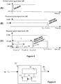
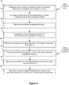
- FIG. 5 is a flowchart of a particular embodiment of the method according to the invention, implemented by the master controller C 1 of figure 3 .
- This algorithm more particularly synthesizes the running of the different steps needed for monitoring the portion 250 of the electrical power supply line of a seismic cable. Using an optical loop
- the master controller C 1 sends, via the optical source 310, the optical controller test signal 315 through the portion 240 of the optical transmission line between the master controller C 1 and slave controller C 2 .
- An example of test signal emitted by the controller C 1 is represented on the chronogram (A) of Figure 4 .
- the master controller C 1 receives, via the optical sensor 320, an optical return signal 325.
- This return signal 325 is supposed to result from a reflection of the optical test signal 315 by the slave controller, and more precisely by the optical reflective mirror 360 comprised in the slave controller C 2 .
- An example of a return signal received by the controller C 1 is represented on the chronogram (B) of Figure 4 .
- the return signal illustrated here is the reference optical signal resulting from the reflection of the optical test signal on the reflective mirror 360 arranged at the end of optical line.
- the reflective mirror 360 has typically a return loss coefficient typically upper than - 15dB.
- the master controller C 1 then processes the optical return signal 325.
- the master controller C 1 determines the effective duration (T) elapsed between an emission instant of the test signal 315 and a reception instant of the optical return signal 325, in order to compare it with a reference duration of a first type, hereafter referenced T ref .
- the reference duration of the first type T ref is understood to be the expected propagation duration necessary to an optical signal to propagate on the optical loop, starting from the master controller C 1 , passing through the slave controller C 2 and coming back to the master controller C 1 .
- the master controller C 1 makes a check to see if the effective duration T determined in the previous step is equal to the reference duration of the first type T ref .
- the master controller C 1 If the effective duration T is equal to the reference duration of the first type T ref , the master controller C 1 considers that the portion 250 of the electrical line supply line has no failure. Indeed, a positive result of the check step means that the optical loop is closed and the controller master controller C 1 can propagate or continues to propagate the high voltage to the slave controller C 2 via the electrical line portion 250.
- the master controller C 1 If the effective duration T is different from the reference duration of the first type T ref , the master controller C 1 considers that the portion 250 of the electrical line supply line is open or defective. Indeed, a negative result of the check step means that the optical loop is open and the controller master controller C 1 must stop supplying the slave controller C 2 or not propagate the high voltage to the slave controller C 2 via the electrical line portion 250.
- the master controller C 1 generates a first piece of monitoring information as a function of the result of the step 54:
- this first piece of monitoring information is used to know if the electrical line portion 250 is considered as being defective or not defective.
- a negative result of the step 54 means that either no optical return signal has been detected by the optical sensor 320 or the optical return signal 325 detected by the optical sensor 320 does not result from a reflection of the optical test signal 315 by the slave controller C 2 , but results from a reflection of the optical test signal 315 by one of the pairs of connected optical connectors (OM 2 - O10 1 (called P 1 ); O10 2 - O20 1 (called P 2 ); O20 2 - O30 1 (called P 3 ); O30 2 - O40 1 (called P 4 ) ... Op 2 - OS 1 (called P m )) of the cable portion 220.
- the electrical line portion 250 is considered as being open or defective.
- the master controller C 1 makes, at the step 56 , a comparison between the effective duration T determined in the step 53 (i.e. duration elapsed between the emission instant of the test signal 315 and the reception instant of the optical return signal 325) and reference durations of a second type, hereafter referenced reference durations T x .
- a reference duration of the second type T x is understood to be the propagation duration necessary to an optical signal to propagate on an optical sub-loop starting from the master controller C 1 , passing through the pair of optical connector P x , and coming back to the master controller C 1 .
- the signal reflected by the connector is very low ( ⁇ -50 dB or -30 dB) that which is difficult to detect with standard components used for transmission, and this value is the same as the connector is connected or disconnected.
- the optical return signal to be take into account by the master controller C 1 for the signal processing is the one that results from a reflection on the last optical connector placed slave along the optical transmission line portion. Due to the presence of a plurality of optical connectors, and so the plurality of return signals, it is important to note that only the last return signal received by the controller C 1 is taken into account in the processing.
- the chronogram (C) of figure 4 illustrates the reception level of the optical return signals received by master controller C 1 and that results from reflections of the test signal 315 on the pairs of optical connectors P 1 , P 2 et P x .
- the signals 401 and 402 results from a reflection of the test signal by the pairs of connected optical connectors P 1 , P 2 respectively.
- the return signal 403 is the last return signal received by the optical sensor 320. It results from a reflection of the test signal by the pair of optical connector P x which is the last slave connector capable of reflecting the optical signal.
- a right-cleaved physical contact optical connector when disconnected, it has a return loss level (loss of optical signal power resulting from the reflection caused by a discontinuity) (typically upper than -15dB), which is much higher than the same optical connector but connected (typically equal to -30dB).
- the effective duration T determined in the step 53 is then compared with the reference durations of the second type T 1 , T 2 , T 3 , ... ,T m .
- the master controller C 1 generates a second piece of information relative to the location of a failure detected on the electrical power supply line comprised between the two controllers C 1 and C 2 .
- the principle here is thus of detecting the furthest slave optical sub-loop not open in order to provide an additional piece of information on the location of a failure detected on the seismic cable.
- the master controller C 1 then delivers a decision to stop supplying the slave controller C 2 via the portion 250 of the electrical power supply line as a function of the first piece of monitoring information and/or the second piece of monitoring information. Therefore, it is possible not only to stop supplying the slave controller C 2 if the portion of electrical power supply line is detected as defective, but it is also possible to have a piece of information on the location of the failure detected on the electrical power supply line.
- the decision-making process performed at the step 58 can be implemented either by the master controller C 1 as described above or by a remote control system.
- the processing of monitoring information can be carried out at a remote location, for example by a control system placed on-board the 115 vessel, to take a decision to stop supplying the electrical power supply line.
- a step of sending the first second piece of monitoring information and/or the second piece of monitoring information to a remote control system must be done by the controller C 1 prior the execution of step 58.
- An identifier enables the remote control system to identify the master controller C 1 concerned can be also sent with the monitoring information.
- the method described above can be executed either before starting to supply the electrical power supply line (at seismic cable level or at seismic cable portion level) or during operation, for example implemented at regular time interval during optical data communications.
- the technique of monitoring according to the invention can be implemented by a master controller for which the slave controller is placed immediately following (or preceding) the master controller along the seismic. But it can also be implemented by a master controller for which the slave controller is not the immediate successive (or preceding) controller but a following (or preceding) controller separated from the slave controller by at least one controller.
- the technique of monitoring according to the invention can be implemented in a bidirectional way. Indeed, the power supply can be carried out from a master concentrator placed at cable end side towards a slave concentrator placed nearer the seismic vessel, and vice versa.
- FIG 6 shows the simplified structure of a monitoring device 70 according to a particular embodiment of the invention.
- the monitoring device 70 can be the monitoring unit 380 comprised in the master controller C 1 of figure 3 for example.
- the monitoring device 70 comprises a non-volatile memory 73 (e.g. a read-only memory (ROM) or a hard disk), a volatile memory 71 (e.g. a random access memory or RAM) and a processor 72.
- the non-volatile memory 73 is a non-transitory computer-readable carrier medium. It stores executable program code instructions, which are executed by the processor 72 in order to enable implementation of the method described above in relation with figure 5 (method for monitoring an electrical power supply line comprised in a seismic cable).
- the aforementioned program code instructions are transferred from the non-volatile memory 73 to the volatile memory 71 so as to be executed by the processor 72.
- the volatile memory 71 likewise includes registers for storing the variables and parameters required for this execution.
- the processor 72 receives an optical return signal (referenced 74) supposed to result from a reflection of a test signal by the slave controller and carries out the electrical power supply line monitoring as a function of the return signal (corresponding to the steps 52 to 58).
- the processor 72 executes the program code instructions allowing to the device to deliver a decision 75 to stop supplying the electrical power supply line as a function of the return signal 74.
- the invention is not limited to a purely software-based implementation, in the form of computer program instructions, but that it can also be implemented in hardware form or any form combining a hardware portion and a software portion.
- the exemplary embodiment here above described is applied to marine seismic exploration using seismic streamers.
- the invention of course is not limited to this particular field of application and can be applied to other field of application like marine seismic exploration using Ocean Bottom Cables (OBC) for seabed acquisition, for example.
- OBC Ocean Bottom Cables
Landscapes
- Physics & Mathematics (AREA)
- Life Sciences & Earth Sciences (AREA)
- General Physics & Mathematics (AREA)
- Remote Sensing (AREA)
- Engineering & Computer Science (AREA)
- Environmental & Geological Engineering (AREA)
- Acoustics & Sound (AREA)
- Geology (AREA)
- General Life Sciences & Earth Sciences (AREA)
- Geophysics (AREA)
- Analytical Chemistry (AREA)
- Chemical & Material Sciences (AREA)
- Oceanography (AREA)
- Geophysics And Detection Of Objects (AREA)
- Arrangements For Transmission Of Measured Signals (AREA)
- Remote Monitoring And Control Of Power-Distribution Networks (AREA)
Claims (14)
- Verfahren zum Überwachen einer Stromversorgungsleitung, die in einem seismischen Kabel (100) enthalten ist und sich entlang des seismischen Kabels erstreckt, wobei das Verfahren den Schritt des Bereitstellens von Folgendem umfasst:- eines seismischen Kabels,- einer Mehrzahl von seismischen Sensoren (210), die entlang des seismischen Kabels angeordnet sind,
einer Mehrzahl von Master- und Slave-Steuerungen, die entlang des seismischen Kabels angeordnet sind,- einer optischen Übertragungsleitung, die sich entlang des seismischen Kabels erstreckt, um Datensignale von oder hin zu den Master- und Slave-Steuerungen der Mehrzahl zu übertragen,wobei die Stromversorgungsleitung mindestens ein Paar aus Master- und Slave-Steuerung der Mehrzahl versorgt,
dadurch gekennzeichnet, dass für mindestens ein gegebenes Paar aus Master- und Slave-Steuerung (C1, C2) die Master-Steuerung (C1) einen Schritt des Überwachens eines Abschnitts (250) der Stromversorgungsleitung ausführt, die zwischen der Master- und der Slave-Steuerung (C1, C2) enthalten ist, die folgenden Schritte umfassend:- Emittieren (51) eines optischen Testsignals durch einen Abschnitt der optischen Übertragungsleitung (240), die zwischen der Master- und der Slave-Steuerung enthalten ist, um eine optische Schleife zu bilden, die von der Master-Steuerung (C1) ausgeht und durch die Slave-Steuerung (C2) verläuft,- Empfangen (52) eine optischen Rücklaufsignals, das aus einer Reflexion des Testsignal durch die Slave-Steuerung entstehen soll,und dass der Abschnitt der Stromversorgungsleitung als eine Funktion des Rücklaufsignals überwacht wird. - Verfahren nach Anspruch 1, wobei die Master-Steuerung ferner Folgendes ausführt:- einen Schritt des Bestimmens (53) einer effektiven Fortpflanzungsdauer, die zwischen einem Moment der Emission des optischen Testsignals und einem Moment des Empfangs des optischen Rücklaufsignals verstrichen ist,- einen ersten Schritt des Vergleichens (54) der effektiven Fortpflanzungsdauer mit einer ersten Referenzfortpflanzungsdauer, die wie eine Funktion einer festgelegten Entfernung (L) ist, welche die Master- und die Slave-Steuerungen trennt,- einen Schritt des Beziehens (55) eines ersten Teils von Überwachungsinformationen als eine Funktion des Ergebnisses des ersten Schritts des Vergleichens.
- Verfahren nach Anspruch 2, wobei mindestens ein gegebenes Paar aus Master- und Slave-Steuerung (C1, C2) durch einen Kabelabschnitt (220) getrennt ist, der eine Mehrzahl von Kabelteilabschnitten (S10 bis Sp) umfasst, wobei jeder Kabelteilabschnitt an beiden Enden des Kabelteilabschnitts ein optisches Verbindungsstück umfasst,
und wobei die Master-Steuerung, wenn sich die effektive Fortpflanzungsdauer von der ersten Referenzfortpflanzungsdauer unterscheidet, ferner Folgendes ausführt:- einen zweiten Schritt des Vergleichens (56) der effektiven Fortpflanzungsdauer mit mindestens einer zweiten Referenzfortpflanzungsdauer, die jede wie eine Funktion einer festgelegten Entfernung (L1, L2, L3) ist, welche die Master-Steuerung und eines der optischen Verbindungsstücke des Kabelabschnitts (220) trennt,- einen zweiten Schritt des Beziehens (57) eines zweiten Teils von Überwachungsinformationen als eine Funktion des Ergebnisses des zweiten Schritts des Vergleichens. - Verfahren nach einem der Ansprüche 2 und 3, wobei die Master-Steuerung ferner die folgenden Schritte ausführt:- Verarbeiten des ersten Teils von Überwachungsinformationen und optional des zweiten Teils von Überwachungsinformationen,- Liefern (58) einer positiven oder negativen Entscheidung zum Unterbrechen der Versorgung der Slave-Steuerung über den Abschnitt der Stromversorgungsleitung als eine Funktion des Ergebnisses des Schritts des Verarbeitens.
- Verfahren nach einem der Ansprüche 2 und 3, wobei die Master-Steuerung ferner einen Schritt des Sendes des ersten zweiten Teils von Überwachungsinformationen und optional des zweiten Teils von Überwachungsinformationen an ein fernes Steuersystem, begleitet von einer Kennung der Master-Steuerung, ausführt, um eine positive oder negative Entscheidung zum Unterbrechen der Versorgung über die Stromversorgungsleitung vorzunehmen.
- System zum Überwachen einer Stromversorgungsleitung, die in einem seismischen Kabel enthalten ist und sich entlang des seismischen Kabels erstreckt, wobei das System Folgendes umfasst:- ein seismisches Kabel,- eine Mehrzahl von seismischen Sensoren (210), die entlang des seismischen Kabels angeordnet sind,
eine Mehrzahl von Master- und Slave-Steuerungen, die entlang des seismischen Kabels angeordnet sind,- eine optische Übertragungsleitung (240), die sich entlang des seismischen Kabels erstreckt, um Datensignale von oder hin zu den Master- und Slave-Steuerungen der Mehrzahl zu übertragen,wobei die Stromversorgungsleitung mindestens ein Paar aus Master- und Slave-Steuerung der Mehrzahl versorgt,
dadurch gekennzeichnet, dass es für mindestens ein gegebenes Paar aus Master- und Slave-Steuerung (C1, C2) ferner Folgendes umfasst:- optische Mittel, die dafür angeordnet sind, mit einem Abschnitt der optischen Übertragungsleitung zusammenzuarbeiten, die zwischen der Master- und der Slave-Steuerung (C1, C2) enthalten ist, um eine optische Schleife zu bilden, die von der Master-Steuerung (C1) ausgeht und durch die Slave-Steuerung (C2) verläuft,- Mittel zum Überwachen, welche die optische Schleife verwenden, um einen Abschnitt der Stromversorgungsleitung zu überwachen, die zwischen der Master- und der Slave-Steuerung (C1, C2) enthalten ist,wobei die optischen Mittel Folgendes umfassen:- an der Seite der Master-Steuerung (C1):• eine optische Quelle (310), die dafür angeordnet ist, ein optisches Testsignal durch den Abschnitt der optischen Übertragungsleitung zu erzeugen,• einen optischen Sensor (320), der dafür angeordnet ist, ein optisches Rücklaufsignal zu empfangen, das aus einer Reflexion des Testsignals durch reflektierende Mittel entstehen soll, die in der Slave-Steuerung enthalten sind,- an der Seite der Slave-Steuerung (C2):• die lichtsignalreflektierenden Mittel (360), die zum Reflektieren des optischen Testsignals angeordnet sind, das von der Master-Steuerung kommt. - System nach Anspruch 6, wobei die Mittel zum Überwachen Mittel zum Verarbeiten des optischen Rücklaufsignals umfassen, das von dem optischen Sensor empfangen wird.
- System nach einem der Ansprüche 6 und 7, wobei die lichtsignalreflektierenden Mittel ein Gerät umfassen, das einen Rücklaufverlust-Koeffizienten aufweist, der über-15 dB liegt.
- System nach Anspruch 8, wobei das Gerät zu der folgenden Gruppe gehört:- ein optisch reflektierender Spiegel,- ein nicht verbundenes rechtsgeschnittenes physisch kontaktierendes optisches Verbindungsstück.
- System nach einem der Ansprüche 6 bis 8, wobei das mindestens eine gegebene Paar aus Master- und Slave-Steuerung (C1, C2) durch einen Kabelabschnitt (220) getrennt sind, der eine Mehrzahl von Kabelteilabschnitten umfasst, wobei jeder Kabelteilabschnitt an beiden Enden des Kabelteilabschnitts ein optisches Verbindungsstück umfasst, der einen Rücklaufverlust-Koeffizienten aufweist, der über -15dB liegt, wenn es nicht verbunden ist.
- System nach Anspruch 10, wobei jedes optische Verbindungsstück ein rechtsgeschnittenes physisch kontaktierendes optisches Verbindungsstück ist.
- System nach einem der Ansprüche 6 bis 11, wobei das seismische Kabel (100) zu der Gruppe gehört, die Folgendes umfasst:- eine seismische Hydrophonkette,ein Unterseekabel.
- Computerprogrammprodukt, dadurch gekennzeichnet, dass es Programmcodebefehle umfasst, um ein System nach einem der Ansprüche 6 bis 12 zu veranlassen, die Schritte des Verfahrens nach einem der Ansprüche 1 bis 5 auszuführen.
- Nicht-flüchtiges, computerlesbares Trägermedium, das ein Computerprogrammprodukt nach Anspruch 13 speichert.
Priority Applications (7)
| Application Number | Priority Date | Filing Date | Title |
|---|---|---|---|
| EP14305240.5A EP2910977B1 (de) | 2014-02-21 | 2014-02-21 | Verfahren zur Überwachung einer Stromversorgungsleitung in einem seismischen Kabel, entsprechendes System, Computerprogrammprodukt und nicht transitorisches computerlesbares Trägermedium |
| CA2881346A CA2881346A1 (en) | 2014-02-21 | 2015-02-05 | Method for monitoring an electrical power supply line comprised in a seismic cable, corresponding system, computer program product and non-transitory computer-readable carrier medium |
| BR102015003300-1A BR102015003300A2 (pt) | 2014-02-21 | 2015-02-13 | Método para monitorar uma linha de fonte de alimentação elétrica compreendida em um cabo sísmico, sistema correspondente, produto de programa de computador e meio condutor legível por computador não transitório |
| CN201510084481.3A CN104865612B (zh) | 2014-02-21 | 2015-02-16 | 用于监测包含在地震电缆中的电力供应线路的方法及系统 |
| MX2015002157A MX350961B (es) | 2014-02-21 | 2015-02-18 | Método para monitorear una línea de suministro de energía eléctrica comprendida en un cable sísmico, y correspondiente sistema, producto de programa de computación y medio portador legible por computadora no transitorio. |
| RU2015105994A RU2672768C2 (ru) | 2014-02-21 | 2015-02-20 | Способ контроля линии электропитания, содержащейся в сейсмическом кабеле, соответствующая система и машиночитаемый носитель информации |
| US14/629,035 US9766281B2 (en) | 2014-02-21 | 2015-02-23 | Method for monitoring an electrical power supply line comprised in a seismic cable, corresponding system, computer program product and non-transitory computer-readable carrier medium |
Applications Claiming Priority (1)
| Application Number | Priority Date | Filing Date | Title |
|---|---|---|---|
| EP14305240.5A EP2910977B1 (de) | 2014-02-21 | 2014-02-21 | Verfahren zur Überwachung einer Stromversorgungsleitung in einem seismischen Kabel, entsprechendes System, Computerprogrammprodukt und nicht transitorisches computerlesbares Trägermedium |
Publications (2)
| Publication Number | Publication Date |
|---|---|
| EP2910977A1 EP2910977A1 (de) | 2015-08-26 |
| EP2910977B1 true EP2910977B1 (de) | 2020-08-05 |
Family
ID=50236127
Family Applications (1)
| Application Number | Title | Priority Date | Filing Date |
|---|---|---|---|
| EP14305240.5A Not-in-force EP2910977B1 (de) | 2014-02-21 | 2014-02-21 | Verfahren zur Überwachung einer Stromversorgungsleitung in einem seismischen Kabel, entsprechendes System, Computerprogrammprodukt und nicht transitorisches computerlesbares Trägermedium |
Country Status (7)
| Country | Link |
|---|---|
| US (1) | US9766281B2 (de) |
| EP (1) | EP2910977B1 (de) |
| CN (1) | CN104865612B (de) |
| BR (1) | BR102015003300A2 (de) |
| CA (1) | CA2881346A1 (de) |
| MX (1) | MX350961B (de) |
| RU (1) | RU2672768C2 (de) |
Families Citing this family (5)
| Publication number | Priority date | Publication date | Assignee | Title |
|---|---|---|---|---|
| EP2910977B1 (de) * | 2014-02-21 | 2020-08-05 | Sercel | Verfahren zur Überwachung einer Stromversorgungsleitung in einem seismischen Kabel, entsprechendes System, Computerprogrammprodukt und nicht transitorisches computerlesbares Trägermedium |
| EP3430415B1 (de) * | 2016-03-15 | 2020-10-21 | Schlumberger Technology B.V. | System und verfahren zur erkennung von leckstrom in einem seismischen landsystem |
| US11079506B2 (en) | 2016-12-16 | 2021-08-03 | Pgs Geophysical As | Multicomponent streamer |
| US10964668B2 (en) | 2017-02-28 | 2021-03-30 | Pgs Geophysical As | Stacked transistor packages |
| US12461265B2 (en) | 2021-12-16 | 2025-11-04 | Pgs Geophysical As | Seismic data acquisition with extended dynamic range |
Family Cites Families (14)
| Publication number | Priority date | Publication date | Assignee | Title |
|---|---|---|---|---|
| US4408307A (en) * | 1978-12-26 | 1983-10-04 | Texas Instruments Incorporated | Optical transmission of digital seismic data |
| US4394616A (en) * | 1980-11-17 | 1983-07-19 | Geosource Inc. | Cable break locator |
| US5303202A (en) * | 1993-09-01 | 1994-04-12 | Carroll Paul E | Method for detecting breaks in geophone cables for seismic data acquisition system |
| CA2264632C (en) * | 1997-05-02 | 2007-11-27 | Baker Hughes Incorporated | Wellbores utilizing fiber optic-based sensors and operating devices |
| US20040105533A1 (en) * | 1998-08-07 | 2004-06-03 | Input/Output, Inc. | Single station wireless seismic data acquisition method and apparatus |
| NO309695B1 (no) * | 1999-02-10 | 2001-03-12 | Geco As | Åpen krets-detektor og fremgangsmåte for påvisning av en åpen krets i systemer for innsamling av seismiske data basert på deteksjon av impedansendringer |
| EP1999761A4 (de) * | 2006-03-24 | 2012-08-29 | Korea Electrotech Res Inst | Stromkabel mit der fähigkeit zur detektion eines fehlers |
| GB0606010D0 (en) * | 2006-03-25 | 2006-05-03 | Qinetiq Ltd | Fibre-Optic Sensor Array |
| US7366055B2 (en) * | 2006-05-05 | 2008-04-29 | Optoplan As | Ocean bottom seismic sensing system |
| CN105910633B (zh) * | 2009-05-27 | 2019-10-29 | 希里克萨有限公司 | 光学传感器及使用方法 |
| CN102970094B (zh) * | 2012-11-08 | 2015-02-25 | 浙江大学 | 一种海底观测网接驳盒时间同步方法 |
| EP2910977B1 (de) * | 2014-02-21 | 2020-08-05 | Sercel | Verfahren zur Überwachung einer Stromversorgungsleitung in einem seismischen Kabel, entsprechendes System, Computerprogrammprodukt und nicht transitorisches computerlesbares Trägermedium |
| US9519278B2 (en) * | 2014-06-09 | 2016-12-13 | Richard J. Petrocy | Modularized self-addressing apparatus and method |
| US9074742B1 (en) * | 2014-06-09 | 2015-07-07 | Richard J. Petrocy | Modularized display apparatus and method |
-
2014
- 2014-02-21 EP EP14305240.5A patent/EP2910977B1/de not_active Not-in-force
-
2015
- 2015-02-05 CA CA2881346A patent/CA2881346A1/en not_active Abandoned
- 2015-02-13 BR BR102015003300-1A patent/BR102015003300A2/pt not_active Application Discontinuation
- 2015-02-16 CN CN201510084481.3A patent/CN104865612B/zh not_active Expired - Fee Related
- 2015-02-18 MX MX2015002157A patent/MX350961B/es active IP Right Grant
- 2015-02-20 RU RU2015105994A patent/RU2672768C2/ru not_active IP Right Cessation
- 2015-02-23 US US14/629,035 patent/US9766281B2/en not_active Expired - Fee Related
Non-Patent Citations (1)
| Title |
|---|
| None * |
Also Published As
| Publication number | Publication date |
|---|---|
| MX350961B (es) | 2017-09-27 |
| RU2672768C2 (ru) | 2018-11-19 |
| CA2881346A1 (en) | 2015-08-21 |
| US20150241497A1 (en) | 2015-08-27 |
| BR102015003300A2 (pt) | 2018-03-13 |
| RU2015105994A (ru) | 2016-09-10 |
| EP2910977A1 (de) | 2015-08-26 |
| MX2015002157A (es) | 2015-08-20 |
| US9766281B2 (en) | 2017-09-19 |
| CN104865612B (zh) | 2019-12-24 |
| RU2015105994A3 (de) | 2018-07-12 |
| CN104865612A (zh) | 2015-08-26 |
Similar Documents
| Publication | Publication Date | Title |
|---|---|---|
| EP2910977B1 (de) | Verfahren zur Überwachung einer Stromversorgungsleitung in einem seismischen Kabel, entsprechendes System, Computerprogrammprodukt und nicht transitorisches computerlesbares Trägermedium | |
| US4092629A (en) | Decentralized seismic data processing system | |
| EP2977787B1 (de) | System und verfahren zur überwachung der leistung eines optischen subsystems in cloud-lidar-systemen | |
| US4628493A (en) | Sensor system with time division multiplexing telemetry | |
| US7660192B2 (en) | Seismic streamer receiver selection systems and methods | |
| EP2249184A1 (de) | Verfahren und System zur passiven akustischen Überwachung in seismischen Aufnahmeoperationen | |
| US8351293B2 (en) | Multi-vessel communication system | |
| NO20241047A1 (en) | Monitoring marine seismic cables with optical fiber | |
| CN103728658B (zh) | 容许供电和/或数据传输线故障的地震勘探的地震电缆 | |
| Ellmauthaler et al. | Distributed acoustic sensing of subsea wells | |
| EP3009865B1 (de) | Elektrisch isolierter streamerabschnitt | |
| Lentz et al. | Scientific monitoring and reliable telecommunications (SMART) cable systems: integration of sensors into telecommunications repeaters | |
| EP3018498B1 (de) | Seismische detektionsleitung mit identifizierten elementen und betriebsverfahren | |
| FR3114206A1 (fr) | Système et Procédé pour la détection de défauts dans des guides d’ondes allongés. | |
| CN110412651A (zh) | 一种分段式海洋地震电缆 | |
| EP2757390B1 (de) | Erfassungsvorrichtung mit Mitteln zur Erkennung einer Verbindungstrennung eines Satzes aus mindestens einem analogen seismischen Sensor | |
| US20150346366A1 (en) | Seismic acquisition system comprising at least one connecting module to which is connected an auxiliary equipment, corresponding connecting module and data management system | |
| US8483010B2 (en) | Providing communications redundancy using one or more loop connections in a subterranean survey system | |
| Lentz | New applications for submarine cables | |
| CN111638554A (zh) | 海洋地震数据接收系统及数据处理方法 | |
| EP4545918A1 (de) | Quasiverteilte erfassung unter verwendung verbesserter erfassungsstrukturen | |
| CA2730813A1 (en) | Method for towing marine sensor streamers | |
| US20170310388A1 (en) | Analyzing Optical Networks | |
| US4908802A (en) | Apparatus for fiber optic seismic exploration system | |
| CN119936971A (zh) | 一种地震数据采集系统 |
Legal Events
| Date | Code | Title | Description |
|---|---|---|---|
| PUAI | Public reference made under article 153(3) epc to a published international application that has entered the european phase |
Free format text: ORIGINAL CODE: 0009012 |
|
| AK | Designated contracting states |
Kind code of ref document: A1 Designated state(s): AL AT BE BG CH CY CZ DE DK EE ES FI FR GB GR HR HU IE IS IT LI LT LU LV MC MK MT NL NO PL PT RO RS SE SI SK SM TR |
|
| AX | Request for extension of the european patent |
Extension state: BA ME |
|
| 17P | Request for examination filed |
Effective date: 20150909 |
|
| RBV | Designated contracting states (corrected) |
Designated state(s): AL AT BE BG CH CY CZ DE DK EE ES FI FR GB GR HR HU IE IS IT LI LT LU LV MC MK MT NL NO PL PT RO RS SE SI SK SM TR |
|
| 17Q | First examination report despatched |
Effective date: 20160620 |
|
| STAA | Information on the status of an ep patent application or granted ep patent |
Free format text: STATUS: EXAMINATION IS IN PROGRESS |
|
| GRAP | Despatch of communication of intention to grant a patent |
Free format text: ORIGINAL CODE: EPIDOSNIGR1 |
|
| STAA | Information on the status of an ep patent application or granted ep patent |
Free format text: STATUS: GRANT OF PATENT IS INTENDED |
|
| INTG | Intention to grant announced |
Effective date: 20200514 |
|
| GRAS | Grant fee paid |
Free format text: ORIGINAL CODE: EPIDOSNIGR3 |
|
| GRAA | (expected) grant |
Free format text: ORIGINAL CODE: 0009210 |
|
| STAA | Information on the status of an ep patent application or granted ep patent |
Free format text: STATUS: THE PATENT HAS BEEN GRANTED |
|
| AK | Designated contracting states |
Kind code of ref document: B1 Designated state(s): AL AT BE BG CH CY CZ DE DK EE ES FI FR GB GR HR HU IE IS IT LI LT LU LV MC MK MT NL NO PL PT RO RS SE SI SK SM TR |
|
| REG | Reference to a national code |
Ref country code: GB Ref legal event code: FG4D |
|
| REG | Reference to a national code |
Ref country code: CH Ref legal event code: EP |
|
| REG | Reference to a national code |
Ref country code: AT Ref legal event code: REF Ref document number: 1299503 Country of ref document: AT Kind code of ref document: T Effective date: 20200815 |
|
| REG | Reference to a national code |
Ref country code: DE Ref legal event code: R096 Ref document number: 602014068522 Country of ref document: DE |
|
| REG | Reference to a national code |
Ref country code: IE Ref legal event code: FG4D |
|
| REG | Reference to a national code |
Ref country code: NL Ref legal event code: FP |
|
| REG | Reference to a national code |
Ref country code: NO Ref legal event code: T2 Effective date: 20200805 Ref country code: LT Ref legal event code: MG4D |
|
| REG | Reference to a national code |
Ref country code: AT Ref legal event code: MK05 Ref document number: 1299503 Country of ref document: AT Kind code of ref document: T Effective date: 20200805 |
|
| PG25 | Lapsed in a contracting state [announced via postgrant information from national office to epo] |
Ref country code: SE Free format text: LAPSE BECAUSE OF FAILURE TO SUBMIT A TRANSLATION OF THE DESCRIPTION OR TO PAY THE FEE WITHIN THE PRESCRIBED TIME-LIMIT Effective date: 20200805 Ref country code: HR Free format text: LAPSE BECAUSE OF FAILURE TO SUBMIT A TRANSLATION OF THE DESCRIPTION OR TO PAY THE FEE WITHIN THE PRESCRIBED TIME-LIMIT Effective date: 20200805 Ref country code: FI Free format text: LAPSE BECAUSE OF FAILURE TO SUBMIT A TRANSLATION OF THE DESCRIPTION OR TO PAY THE FEE WITHIN THE PRESCRIBED TIME-LIMIT Effective date: 20200805 Ref country code: LT Free format text: LAPSE BECAUSE OF FAILURE TO SUBMIT A TRANSLATION OF THE DESCRIPTION OR TO PAY THE FEE WITHIN THE PRESCRIBED TIME-LIMIT Effective date: 20200805 Ref country code: BG Free format text: LAPSE BECAUSE OF FAILURE TO SUBMIT A TRANSLATION OF THE DESCRIPTION OR TO PAY THE FEE WITHIN THE PRESCRIBED TIME-LIMIT Effective date: 20201105 Ref country code: AT Free format text: LAPSE BECAUSE OF FAILURE TO SUBMIT A TRANSLATION OF THE DESCRIPTION OR TO PAY THE FEE WITHIN THE PRESCRIBED TIME-LIMIT Effective date: 20200805 Ref country code: PT Free format text: LAPSE BECAUSE OF FAILURE TO SUBMIT A TRANSLATION OF THE DESCRIPTION OR TO PAY THE FEE WITHIN THE PRESCRIBED TIME-LIMIT Effective date: 20201207 Ref country code: GR Free format text: LAPSE BECAUSE OF FAILURE TO SUBMIT A TRANSLATION OF THE DESCRIPTION OR TO PAY THE FEE WITHIN THE PRESCRIBED TIME-LIMIT Effective date: 20201106 Ref country code: ES Free format text: LAPSE BECAUSE OF FAILURE TO SUBMIT A TRANSLATION OF THE DESCRIPTION OR TO PAY THE FEE WITHIN THE PRESCRIBED TIME-LIMIT Effective date: 20200805 |
|
| PG25 | Lapsed in a contracting state [announced via postgrant information from national office to epo] |
Ref country code: IS Free format text: LAPSE BECAUSE OF FAILURE TO SUBMIT A TRANSLATION OF THE DESCRIPTION OR TO PAY THE FEE WITHIN THE PRESCRIBED TIME-LIMIT Effective date: 20201205 Ref country code: PL Free format text: LAPSE BECAUSE OF FAILURE TO SUBMIT A TRANSLATION OF THE DESCRIPTION OR TO PAY THE FEE WITHIN THE PRESCRIBED TIME-LIMIT Effective date: 20200805 Ref country code: RS Free format text: LAPSE BECAUSE OF FAILURE TO SUBMIT A TRANSLATION OF THE DESCRIPTION OR TO PAY THE FEE WITHIN THE PRESCRIBED TIME-LIMIT Effective date: 20200805 Ref country code: LV Free format text: LAPSE BECAUSE OF FAILURE TO SUBMIT A TRANSLATION OF THE DESCRIPTION OR TO PAY THE FEE WITHIN THE PRESCRIBED TIME-LIMIT Effective date: 20200805 |
|
| PG25 | Lapsed in a contracting state [announced via postgrant information from national office to epo] |
Ref country code: RO Free format text: LAPSE BECAUSE OF FAILURE TO SUBMIT A TRANSLATION OF THE DESCRIPTION OR TO PAY THE FEE WITHIN THE PRESCRIBED TIME-LIMIT Effective date: 20200805 Ref country code: SM Free format text: LAPSE BECAUSE OF FAILURE TO SUBMIT A TRANSLATION OF THE DESCRIPTION OR TO PAY THE FEE WITHIN THE PRESCRIBED TIME-LIMIT Effective date: 20200805 Ref country code: CZ Free format text: LAPSE BECAUSE OF FAILURE TO SUBMIT A TRANSLATION OF THE DESCRIPTION OR TO PAY THE FEE WITHIN THE PRESCRIBED TIME-LIMIT Effective date: 20200805 Ref country code: DK Free format text: LAPSE BECAUSE OF FAILURE TO SUBMIT A TRANSLATION OF THE DESCRIPTION OR TO PAY THE FEE WITHIN THE PRESCRIBED TIME-LIMIT Effective date: 20200805 Ref country code: EE Free format text: LAPSE BECAUSE OF FAILURE TO SUBMIT A TRANSLATION OF THE DESCRIPTION OR TO PAY THE FEE WITHIN THE PRESCRIBED TIME-LIMIT Effective date: 20200805 |
|
| REG | Reference to a national code |
Ref country code: DE Ref legal event code: R097 Ref document number: 602014068522 Country of ref document: DE |
|
| PG25 | Lapsed in a contracting state [announced via postgrant information from national office to epo] |
Ref country code: AL Free format text: LAPSE BECAUSE OF FAILURE TO SUBMIT A TRANSLATION OF THE DESCRIPTION OR TO PAY THE FEE WITHIN THE PRESCRIBED TIME-LIMIT Effective date: 20200805 |
|
| PLBE | No opposition filed within time limit |
Free format text: ORIGINAL CODE: 0009261 |
|
| STAA | Information on the status of an ep patent application or granted ep patent |
Free format text: STATUS: NO OPPOSITION FILED WITHIN TIME LIMIT |
|
| PG25 | Lapsed in a contracting state [announced via postgrant information from national office to epo] |
Ref country code: SK Free format text: LAPSE BECAUSE OF FAILURE TO SUBMIT A TRANSLATION OF THE DESCRIPTION OR TO PAY THE FEE WITHIN THE PRESCRIBED TIME-LIMIT Effective date: 20200805 |
|
| 26N | No opposition filed |
Effective date: 20210507 |
|
| PG25 | Lapsed in a contracting state [announced via postgrant information from national office to epo] |
Ref country code: IT Free format text: LAPSE BECAUSE OF FAILURE TO SUBMIT A TRANSLATION OF THE DESCRIPTION OR TO PAY THE FEE WITHIN THE PRESCRIBED TIME-LIMIT Effective date: 20200805 |
|
| PG25 | Lapsed in a contracting state [announced via postgrant information from national office to epo] |
Ref country code: SI Free format text: LAPSE BECAUSE OF FAILURE TO SUBMIT A TRANSLATION OF THE DESCRIPTION OR TO PAY THE FEE WITHIN THE PRESCRIBED TIME-LIMIT Effective date: 20200805 |
|
| REG | Reference to a national code |
Ref country code: DE Ref legal event code: R119 Ref document number: 602014068522 Country of ref document: DE |
|
| REG | Reference to a national code |
Ref country code: NO Ref legal event code: MMEP |
|
| PG25 | Lapsed in a contracting state [announced via postgrant information from national office to epo] |
Ref country code: MC Free format text: LAPSE BECAUSE OF FAILURE TO SUBMIT A TRANSLATION OF THE DESCRIPTION OR TO PAY THE FEE WITHIN THE PRESCRIBED TIME-LIMIT Effective date: 20200805 |
|
| GBPC | Gb: european patent ceased through non-payment of renewal fee |
Effective date: 20210221 |
|
| REG | Reference to a national code |
Ref country code: BE Ref legal event code: MM Effective date: 20210228 |
|
| PG25 | Lapsed in a contracting state [announced via postgrant information from national office to epo] |
Ref country code: CH Free format text: LAPSE BECAUSE OF NON-PAYMENT OF DUE FEES Effective date: 20210228 Ref country code: LU Free format text: LAPSE BECAUSE OF NON-PAYMENT OF DUE FEES Effective date: 20210221 Ref country code: LI Free format text: LAPSE BECAUSE OF NON-PAYMENT OF DUE FEES Effective date: 20210228 |
|
| PG25 | Lapsed in a contracting state [announced via postgrant information from national office to epo] |
Ref country code: NO Free format text: LAPSE BECAUSE OF NON-PAYMENT OF DUE FEES Effective date: 20210228 |
|
| REG | Reference to a national code |
Ref country code: NL Ref legal event code: MM Effective date: 20210301 |
|
| PG25 | Lapsed in a contracting state [announced via postgrant information from national office to epo] |
Ref country code: NL Free format text: LAPSE BECAUSE OF NON-PAYMENT OF DUE FEES Effective date: 20210301 |
|
| PG25 | Lapsed in a contracting state [announced via postgrant information from national office to epo] |
Ref country code: DE Free format text: LAPSE BECAUSE OF NON-PAYMENT OF DUE FEES Effective date: 20210901 Ref country code: GB Free format text: LAPSE BECAUSE OF NON-PAYMENT OF DUE FEES Effective date: 20210221 Ref country code: FR Free format text: LAPSE BECAUSE OF NON-PAYMENT OF DUE FEES Effective date: 20210228 Ref country code: IE Free format text: LAPSE BECAUSE OF NON-PAYMENT OF DUE FEES Effective date: 20210221 |
|
| PG25 | Lapsed in a contracting state [announced via postgrant information from national office to epo] |
Ref country code: IS Free format text: LAPSE BECAUSE OF FAILURE TO SUBMIT A TRANSLATION OF THE DESCRIPTION OR TO PAY THE FEE WITHIN THE PRESCRIBED TIME-LIMIT Effective date: 20201205 |
|
| PG25 | Lapsed in a contracting state [announced via postgrant information from national office to epo] |
Ref country code: BE Free format text: LAPSE BECAUSE OF NON-PAYMENT OF DUE FEES Effective date: 20210228 |
|
| PG25 | Lapsed in a contracting state [announced via postgrant information from national office to epo] |
Ref country code: HU Free format text: LAPSE BECAUSE OF FAILURE TO SUBMIT A TRANSLATION OF THE DESCRIPTION OR TO PAY THE FEE WITHIN THE PRESCRIBED TIME-LIMIT; INVALID AB INITIO Effective date: 20140221 |
|
| PG25 | Lapsed in a contracting state [announced via postgrant information from national office to epo] |
Ref country code: CY Free format text: LAPSE BECAUSE OF FAILURE TO SUBMIT A TRANSLATION OF THE DESCRIPTION OR TO PAY THE FEE WITHIN THE PRESCRIBED TIME-LIMIT Effective date: 20200805 |
|
| PG25 | Lapsed in a contracting state [announced via postgrant information from national office to epo] |
Ref country code: MK Free format text: LAPSE BECAUSE OF FAILURE TO SUBMIT A TRANSLATION OF THE DESCRIPTION OR TO PAY THE FEE WITHIN THE PRESCRIBED TIME-LIMIT Effective date: 20200805 |
|
| PG25 | Lapsed in a contracting state [announced via postgrant information from national office to epo] |
Ref country code: TR Free format text: LAPSE BECAUSE OF FAILURE TO SUBMIT A TRANSLATION OF THE DESCRIPTION OR TO PAY THE FEE WITHIN THE PRESCRIBED TIME-LIMIT Effective date: 20200805 |
|
| PG25 | Lapsed in a contracting state [announced via postgrant information from national office to epo] |
Ref country code: MT Free format text: LAPSE BECAUSE OF FAILURE TO SUBMIT A TRANSLATION OF THE DESCRIPTION OR TO PAY THE FEE WITHIN THE PRESCRIBED TIME-LIMIT Effective date: 20200805 |