EP2911032B1 - Dispositif électronique et son capot de protection - Google Patents
Dispositif électronique et son capot de protection Download PDFInfo
- Publication number
- EP2911032B1 EP2911032B1 EP15155954.9A EP15155954A EP2911032B1 EP 2911032 B1 EP2911032 B1 EP 2911032B1 EP 15155954 A EP15155954 A EP 15155954A EP 2911032 B1 EP2911032 B1 EP 2911032B1
- Authority
- EP
- European Patent Office
- Prior art keywords
- cover
- electronic device
- sealing member
- sealing
- catching
- Prior art date
- Legal status (The legal status is an assumption and is not a legal conclusion. Google has not performed a legal analysis and makes no representation as to the accuracy of the status listed.)
- Not-in-force
Links
Images


Classifications
-
- H—ELECTRICITY
- H05—ELECTRIC TECHNIQUES NOT OTHERWISE PROVIDED FOR
- H05K—PRINTED CIRCUITS; CASINGS OR CONSTRUCTIONAL DETAILS OF ELECTRIC APPARATUS; MANUFACTURE OF ASSEMBLAGES OF ELECTRICAL COMPONENTS
- H05K5/00—Casings, cabinets or drawers for electric apparatus
- H05K5/06—Hermetically-sealed casings
- H05K5/061—Hermetically-sealed casings sealed by a gasket held between a removable cover and a body, e.g. O-ring, packing
-
- A—HUMAN NECESSITIES
- A45—HAND OR TRAVELLING ARTICLES
- A45C—PURSES; LUGGAGE; HAND CARRIED BAGS
- A45C11/00—Receptacles for purposes not provided for in groups A45C1/00-A45C9/00
-
- G—PHYSICS
- G06—COMPUTING OR CALCULATING; COUNTING
- G06F—ELECTRIC DIGITAL DATA PROCESSING
- G06F1/00—Details not covered by groups G06F3/00 - G06F13/00 and G06F21/00
- G06F1/16—Constructional details or arrangements
- G06F1/1613—Constructional details or arrangements for portable computers
- G06F1/1633—Constructional details or arrangements of portable computers not specific to the type of enclosures covered by groups G06F1/1615 - G06F1/1626
- G06F1/1635—Details related to the integration of battery packs and other power supplies such as fuel cells or integrated AC adapter
-
- G—PHYSICS
- G06—COMPUTING OR CALCULATING; COUNTING
- G06F—ELECTRIC DIGITAL DATA PROCESSING
- G06F1/00—Details not covered by groups G06F3/00 - G06F13/00 and G06F21/00
- G06F1/16—Constructional details or arrangements
- G06F1/1613—Constructional details or arrangements for portable computers
- G06F1/1633—Constructional details or arrangements of portable computers not specific to the type of enclosures covered by groups G06F1/1615 - G06F1/1626
- G06F1/1656—Details related to functional adaptations of the enclosure, e.g. to provide protection against EMI, shock, water, or to host detachable peripherals like a mouse or removable expansions units like PCMCIA cards, or to provide access to internal components for maintenance or to removable storage supports like CDs or DVDs, or to mechanically mount accessories
-
- H—ELECTRICITY
- H04—ELECTRIC COMMUNICATION TECHNIQUE
- H04M—TELEPHONIC COMMUNICATION
- H04M1/00—Substation equipment, e.g. for use by subscribers
- H04M1/02—Constructional features of telephone sets
- H04M1/0202—Portable telephone sets, e.g. cordless phones, mobile phones or bar type handsets
- H04M1/0249—Details of the mechanical connection between the housing parts or relating to the method of assembly
- H04M1/0252—Details of the mechanical connection between the housing parts or relating to the method of assembly by means of a snap-on mechanism
-
- H—ELECTRICITY
- H04—ELECTRIC COMMUNICATION TECHNIQUE
- H04M—TELEPHONIC COMMUNICATION
- H04M1/00—Substation equipment, e.g. for use by subscribers
- H04M1/02—Constructional features of telephone sets
- H04M1/18—Telephone sets specially adapted for use in ships, mines, or other places exposed to adverse environment
-
- H—ELECTRICITY
- H05—ELECTRIC TECHNIQUES NOT OTHERWISE PROVIDED FOR
- H05K—PRINTED CIRCUITS; CASINGS OR CONSTRUCTIONAL DETAILS OF ELECTRIC APPARATUS; MANUFACTURE OF ASSEMBLAGES OF ELECTRICAL COMPONENTS
- H05K5/00—Casings, cabinets or drawers for electric apparatus
- H05K5/0086—Casings, cabinets or drawers for electric apparatus portable, e.g. battery operated apparatus
-
- H—ELECTRICITY
- H05—ELECTRIC TECHNIQUES NOT OTHERWISE PROVIDED FOR
- H05K—PRINTED CIRCUITS; CASINGS OR CONSTRUCTIONAL DETAILS OF ELECTRIC APPARATUS; MANUFACTURE OF ASSEMBLAGES OF ELECTRICAL COMPONENTS
- H05K5/00—Casings, cabinets or drawers for electric apparatus
- H05K5/02—Details
- H05K5/0247—Electrical details of casings, e.g. terminals, passages for cables or wiring
-
- H—ELECTRICITY
- H05—ELECTRIC TECHNIQUES NOT OTHERWISE PROVIDED FOR
- H05K—PRINTED CIRCUITS; CASINGS OR CONSTRUCTIONAL DETAILS OF ELECTRIC APPARATUS; MANUFACTURE OF ASSEMBLAGES OF ELECTRICAL COMPONENTS
- H05K5/00—Casings, cabinets or drawers for electric apparatus
- H05K5/02—Details
- H05K5/03—Covers
-
- H—ELECTRICITY
- H05—ELECTRIC TECHNIQUES NOT OTHERWISE PROVIDED FOR
- H05K—PRINTED CIRCUITS; CASINGS OR CONSTRUCTIONAL DETAILS OF ELECTRIC APPARATUS; MANUFACTURE OF ASSEMBLAGES OF ELECTRICAL COMPONENTS
- H05K5/00—Casings, cabinets or drawers for electric apparatus
- H05K5/10—Casings, cabinets or drawers for electric apparatus comprising several parts forming a closed casing
- H05K5/15—Casings, cabinets or drawers for electric apparatus comprising several parts forming a closed casing assembled by resilient members
-
- H—ELECTRICITY
- H04—ELECTRIC COMMUNICATION TECHNIQUE
- H04M—TELEPHONIC COMMUNICATION
- H04M1/00—Substation equipment, e.g. for use by subscribers
- H04M1/02—Constructional features of telephone sets
- H04M1/0202—Portable telephone sets, e.g. cordless phones, mobile phones or bar type handsets
- H04M1/026—Details of the structure or mounting of specific components
- H04M1/0262—Details of the structure or mounting of specific components for a battery compartment
-
- H—ELECTRICITY
- H04—ELECTRIC COMMUNICATION TECHNIQUE
- H04M—TELEPHONIC COMMUNICATION
- H04M1/00—Substation equipment, e.g. for use by subscribers
- H04M1/72—Mobile telephones; Cordless telephones, i.e. devices for establishing wireless links to base stations without route selection
- H04M1/724—User interfaces specially adapted for cordless or mobile telephones
- H04M1/72448—User interfaces specially adapted for cordless or mobile telephones with means for adapting the functionality of the device according to specific conditions
- H04M1/7246—User interfaces specially adapted for cordless or mobile telephones with means for adapting the functionality of the device according to specific conditions by connection of exchangeable housing parts
-
- H—ELECTRICITY
- H04—ELECTRIC COMMUNICATION TECHNIQUE
- H04M—TELEPHONIC COMMUNICATION
- H04M2250/00—Details of telephonic subscriber devices
- H04M2250/04—Details of telephonic subscriber devices including near field communication means, e.g. RFID
-
- Y—GENERAL TAGGING OF NEW TECHNOLOGICAL DEVELOPMENTS; GENERAL TAGGING OF CROSS-SECTIONAL TECHNOLOGIES SPANNING OVER SEVERAL SECTIONS OF THE IPC; TECHNICAL SUBJECTS COVERED BY FORMER USPC CROSS-REFERENCE ART COLLECTIONS [XRACs] AND DIGESTS
- Y02—TECHNOLOGIES OR APPLICATIONS FOR MITIGATION OR ADAPTATION AGAINST CLIMATE CHANGE
- Y02E—REDUCTION OF GREENHOUSE GAS [GHG] EMISSIONS, RELATED TO ENERGY GENERATION, TRANSMISSION OR DISTRIBUTION
- Y02E60/00—Enabling technologies; Technologies with a potential or indirect contribution to GHG emissions mitigation
- Y02E60/10—Energy storage using batteries
Definitions
- the present disclosure relates to an electronic device and a protective cover therefor.
- portable terminals such as a mobile phone, an Motion Picture Expert Group (MPEG) audio layer 3 (MP3) player, a Portable Media Player (PMP), and an electronic book, by which a user can access various contents while carrying the electronic device are widely used.
- MPEG Motion Picture Expert Group
- MP3 Motion Picture Expert Group
- PMP Portable Media Player
- Various functions such as an ability to shoot photos or record moving images, play music, videos, and multimedia, and execute game functions, as well as a wireless transmission/reception function, are being integrated into the portable terminals.
- a display unit is provided on a front surface of the portable terminal, such that the multiple functions can be used, and a recent portable terminal, such as a smart phone, is provided with a display unit through which an entire front surface of the terminal is sensitive to a touch.
- the electronic device such as a portable terminal, is provided with various cases, or protective covers, which may be generally referred to as a cover.
- a battery cover for covering a battery may be provided on a rear surface of the electronic device.
- the battery cover may be variously classified according to a mounting location or a cover state of the electronic device.
- the battery cover may include a form which can be provided only on a rear surface of the electronic device, in detail, a form in which a display is exposed and only a periphery of an external appearance of the electronic device or a rear case is covered such that the display unit is used, or a form in which the entire electronic device is covered through a flip type case and the display unit is covered such that the display unit is used.
- WO 2013/080669 A1 relates to an apparatus comprising a casing having an opening; a lid body for opening/closing the opening; and placed in a gap between the opening and the lid body closing the opening, a ring-shaped dust-proofing member and a ring-shaped waterproofing member that exist for the purpose of sealing the gap.
- the ring-shaped dust-proofing member is placed on the outer edge of the casing relative to the ring-shaped waterproofing member, leaving a space to the ring-shaped waterproofing member.
- the lid body has closed the opening, the ring-shaped dust-proofing member and the ring-shaped waterproofing member are compressed by the casing and the lid body.
- US 2011/293981 A1 relates to a mobile device that includes a housing, a gasket and a lid assembly.
- the housing defines receiving chamber to receive a battery and a receiving groove configured in a circle around the receiving chamber.
- the gasket is received in the receiving groove.
- the lid assembly attached to the housing to cover the receiving chamber includes a first lid and a second lid.
- the first lid includes a projecting rib to engage with the receiving groove to force the gasket in the receiving groove.
- the second lid is slideably attached to the first lid and engages to the housing to force the first lid on the housing.
- the antenna can include a flexible board having a first region and a second region; a high frequency antenna pattern formed in the first region of the flexible board to transceive a wireless signal by detecting a magnetic flux; a low frequency antenna pattern formed in the second region of the flexible board to generate an Induced current; and a magnetic sheet stacked on one surface of the flexible board to simultaneously cover both of the high frequency antenna pattern and the low frequency antenna pattern, the magnetic sheet having a high magnetic permeability for both a high frequency and a low frequency.
- An electronic device such as a portable terminal and an electronic device protective cover, for example, a flip type cover, may include at least one cover according to an in-use environment of the electronic device and/or an in-use form by a user such that the cover may be detachably attached to a body of the electronic device to be replaced.
- the cover may be a rear cover form covering only a rear surface of the body or a flip type form covering both a display unit provided on a front surface of the body and a rear surface of the body, so that a cover, in a form desired by the user, may be replaced in consideration of an in-use environment of the electronic device or a design of the electronic device.
- gaps may be generated in the electronic device due to a need for coupling of components or connection parts with external devices.
- the gaps of the electronic devices may cause various water submersion paths on the electronic device. That is, when moisture is introduced through the gaps generated in the electronic device due to a need for coupling of components or connection parts with external devices, electrical terminals and spaces for attaching a battery may be exposed to the moisture that may damage an internal circuit of the electronic device.
- the battery cover for mounting and covering a battery is engaged with the body of the electronic device, a gap may be generated between the battery cover and the body.
- the electronic device is vulnerable to various water submersion situations due to various gaps generated between the electronic device and the battery cover.
- first, second, etc. can be used for describing various elements, the structural elements are not restricted by the terms. The terms are only used to distinguish one element from another element. For example, without departing from the scope of the present disclosure, a first structural element may be named a second structural element. Similarly, the second structural element also may be named the first structural element. As used herein, the term "and/or" includes any and all combinations of one or more associated items.
- an electronic device may refer to a terminal, a portable terminal, a mobile terminal, a communication terminal, a portable communication terminal, a portable mobile terminal, a display device, and the like.
- the electronic device may be a smartphone, a portable phone, a game player, a Television (TV), a display unit, a heads-up display unit for a vehicle, a notebook computer, a laptop computer, a tablet Personal Computer (PC), a Personal Media Player (PMP), a Personal Digital Assistant (PDA), and the like.
- the electronic device may be implemented as a portable communication terminal which has a wireless communication function and a pocket size.
- the electronic device may be a flexible device or a flexible display unit.
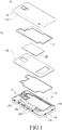
- FIG. 1 is an exploded perspective view schematically showing an electronic device according to an embodiment of the present disclosure.
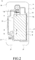
- FIG. 2 is a view showing a state in which an electronic device is coupled according to an embodiment of the present disclosure.
- an electronic device 10 may include a body 11, a cover 12, a first sealing member 13 for sealing a space between the body and the cover, and a second sealing member 15 for sealing the cover in which two configurations are stacked.
- the electronic device 10 may include the body 11 including a rear case 11a and a sealing surface 11b, the cover 12, in which an inner cover 12b and an outer cover 12a are stacked to be coupled to each other, and which includes a finger extraction recess 25 formed at a portion of an end of the outer cover 12a, the first sealing member 13 coupled to an inner surface of the inner cover 12b of the cover 12, an electronic module EM provided between the outer cover 12a and inner cover 12b that are stacked and coupled to each other, and a second sealing member 15 for sealing a space between the outer cover 12a and the inner cover 12b that are stacked and coupled to each other.
- the body 11 may be configured as a smartphone, a mobile phone, a navigation device, a gaming device, a TV, a vehicular head unit, a notebook computer, a laptop computer, a tablet computer, a PMP, a PDA, and any other similar and/or suitable device configuration.
- a screen may be viewed from a front surface of the body 11, and a display unit (not shown), through which an input is realized, may be provided.
- the rear case 11a is coupled to a rear surface of the body 11 to cover internal components of the body 11.
- the rear case 11a may include a battery mounting space S1, hereinafter, referred to as a space S1, such that the space S1 accommodates a battery B.
- the body 11 may also include a coupling unit 21 (see FIG. 2 ) that includes coupling recesses 21a and an auxiliary coupling unit 22 including second fastening parts 22a.
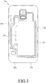
- FIG. 3 is a view schematically showing a rear case of an electronic device according to an embodiment of the present disclosure.
- the sealing surface 11b to which the first sealing member 13 is attached is provided on one surface of the rear case 11a.
- the sealing surface 11b is provided at a peripheral circumference of the space S1 and may be formed in a closed curve shape according the peripheral circumference of the space S1. If the cover 12 is coupled to the rear case 11a on a rear surface of the body 11, the first sealing member 13 is attached to the sealing surface 11b to seal a gap between the body 11 and the cover 12, preventing introduction of moisture or foreign substances into the gap.
- the coupling unit 21 may be provided along a peripheral circumference of the rear case 11a and along a circumference of an end of the cover 12 of the present disclosure, such that the cover 12 may be coupled to a rear surface of the body 11 (see FIGS. 2 and 10 ).
- the coupling unit 21 includes the coupling recesses 21a provided along a peripheral circumference of the rear case 11a, and coupling bosses 21b (see FIGS. 4 and 5 ) provided along a circumference of an end of the cover 11b to be engaged with or released from the coupling recesses 21a.
- the coupling recesses 21a may be formed at a peripheral circumference of the rear case 11a, and the coupling bosses 21b, which may be hook shaped, engaged with the coupling recesses 21a may be formed along an end of the cover 12. Accordingly, the cover 12 may be attached to or detached from the rear case 11b as the coupling bosses 21b is engaged with or released from the coupling recesses 21a.
- a configuration of the coupling unit 21 is not limited thereto. The shape or configuration of the coupling unit 21 may be arbitrarily modified and changed as long as the cover 12 may be coupled while covering a rear surface of the body.
- the second fastening parts 22a which may also be referred to as recessed parts 22a, of the auxiliary coupling unit 22 may be formed between the space S1 of the rear case 11a and the sealing surface 11b of the present disclosure.
- the recessed parts 22a are configured such that first fastening parts 22b, which may also be referred to as catching parts 22b, of the auxiliary coupling unit 22 are caught by or released from the recessed parts 22a, and the first fastening parts 22b are formed in the cover 12. That is, as the catching parts 22b are caught by or released from the recessed parts 22a, the cover 12 may be further attached and coupled to the rear case 11a.
- catching parts 22b which may also be referred to as catching parts 22b
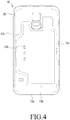
- FIG. 4 is a view showing an outer side of a cover according to an embodiment of the present disclosure.
- FIG. 5 is a view showing an inner side of a cover according to an embodiment of the present disclosure.
- the cover 12 covers a rear surface of the body 11, and may be attached or detached from the rear case 11a.
- the cover 12, may include a form which covers only a rear surface of the body 11, and may also include a form (not shown) which is coupled to a rear surface of the body 11 to cover a front surface of the body 11 as well as a rear surface of the body 11.
- a structure of the cover may include, for example, a first cover such as a front cover and a second cover such as a rear cover.
- the first cover may be rotatably connected to one side of the second cover, and may cover a display unit provided on a first surface of the body 11.
- the second cover may be connected to the front cover, may be coupled to a second surface, such as the rear case 11a, and may cover a rear surface of the electronic device 10 including the space S1 for accommodating the battery B.
- the cover 12 according to an embodiment of the present disclosure, has a structure in which the inner cover 12b and the outer cover 12a are coupled to each other, and the second cover of the flip cover also may have a structure in which the inner cover 12b and the outer cover 12a are coupled to each other.
- the first sealing member 13 provided inside the cover 12 may be provided on an inner side of the second cover of the flip cover (not shown).
- the second cover of the flip cover may be generally referred to as 'a cover'.
- the cover 12 may also be referred to as a cover assembly 12 in which the inner cover 12b and the outer cover 12a are coupled to each other.
- the cover 12 may correspond to one of the cover 12 in which two members, that is, the inner cover 12b and the outer cover 12a are stacked to be coupled to each other so as to form the one of the cover 12 (see FIG. 1 together with FIGS. 7 , 8, and 9 ).
- NFC Near Field Communication
- RFID Radio Frequency Identification
- the cover 12 corresponds to the cover assembly 12, the electronic module EM provided in the inner space S2, as and/or while the inner cover 12b and the outer cover 12a are attached to and detached from each other, may be replaced by an electronic module EM having another function if necessary, and may be replaced as the electronic module EM provided in the inner space S1 malfunctions and/or is damaged.
- the electronic module EM may be replaced before the inner cover 12b and the outer cover 12a are attached to each other.
- the cover assembly 12 may be assembled in a bonded form through a bonding member located between the inner cover 12b and the outer cover 12a.
- the bonded form of the cover assembly 12 is not limited to the bonding member, and may be assembled through an adhesive, thermal fusion, ultrasonic fusion, a catching member, thermal pressing, and through any similar and/or suitable element for bonding and/or method of bonding.
- the inner cover 12b may be manufactured of a plastic material, such as Polycarbonate (PC), Polyphthalamide (PPA), Polyamide (PA), and Acrylonitrile Butadiene Styrene (ABS), may be manufactured of a complex material including a carbon fiber or a glass fiber, and may be manufactured of a metallic material such as Steel Use Stainless (SUS), aluminum, zinc, or magnesium.
- the inner cover 12b may be manufactured of a tape or a sheet.
- the cover 12 may include a coupling boss 22b which is to be coupled to the rear case 11a, the first sealing member 13 for sealing a gap between the body 11 and the cover 12, a second sealing member 15 (see FIG. 7 ) for sealing a gap between the inner cover 12b and the outer cover 12a, and the electronic module EM separately provided from the body 11.
- the cover 12 has a configuration in which the inner cover 12b and the outer cover 12a are coupled to each other.
- the inner cover 12b is stacked on an inner surface of the outer cover 12a, and an inner space S2 (see FIG. 9 ) in which the electronic module EM may be formed between an outer surface of the inner cover 12b and an inner surface of the outer cover 12a (see FIG. 1 together with FIGS. 7 , 8, and 9 ).
- An end of the inner cover 12b is located on the inner side of an end of the outer cover 12a.
- the coupling bosses 21b of the coupling unit 21 may be formed adjacent to each other along a circumference of an end of the inner surface of the outer cover 12a.
- the finger extraction recess 25 may be formed at a portion of an end of the outer cover 12a so that the cover 12 may be separated from the rear case 11a.
- the finger extraction recess 25 is provided at an upper corner of the outer cover 12a. If the finger extraction recess 25 formed at the upper corner of the outer cover 12a is raised while the cover 12 is coupled to the rear case 11a, the cover 12 may be separated from the rear case 11a while the coupling bosses 21b, which are caught by the coupling recesses 21a, are separated.
- a mounting surface 12c, upon which the first sealing member 13 is mounted, is formed on an inner surface of the inner cover 12b.
- the mounting surface 12c may be formed similar to the sealing surface 11b, and the mounting surface 12c also forms a closed curve similar to the sealing surface 11b.
- the mounting surface 12c may be formed to be recessed from an inner surface of the inner cover 12b. In an embodiment of the present disclosure, wherein the mounting surface 12c is recessed from the inner surface of the inner cover 12b, an increase of an overall thickness of the electronic device 10 can be prevented.
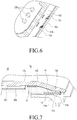
- FIG. 6 is a view showing a catching hook formed on an inner surface of an inner cover according to an embodiment of the present disclosure.
- the catching part 22b of the auxiliary coupling unit 22 may be formed in the inner cover 12b. At least one of the catching part 22b is located on the inner surface of the inner cover 12b, and is located on the inner side of the mounting surface 12c. At least one of the catching part 22b is provided to be opposite to the locations of the recessed parts 22a, and are provided to be positioned in the recessed parts 22a. According to an embodiment of the present disclosure, the catching part 22b may correspond to catching hooks. The catching hooks may be formed to be bent in a direction along which the cover 12 is separated. In further detail, the catching hooks may be bent from one side to an opposite side of the cover 12 having the finger extraction recess 25.
- the cover 12 may be coupled to and engaged with the rear case 11a, and when the cover 12 is separated from the rear case 11a through the finger extraction recess 25, it may be easily separated from the recessed parts 22a.
- the shapes of the catching parts 22b are not limited thereto, and may correspond to catching balls, which will be described below.
- the catching balls may be formed of a resilient material. If the catching balls are introduced into the recessed parts 22a, they may be coupled to the recessed parts 22a while the shapes of the catching balls resiliently vary.
- the cover 12 If the cover 12 is separated from the rear case 11a, it may be separated from the recessed parts 22a while the shapes of the catching balls resiliently vary (see FIG. 11 ).
- the configuration of the auxiliary coupling unit 22 including the catching parts 22b and the recessed parts 22a will be described in detail below.
- FIG. 7 is a view showing a section taken along line A-A' of FIG. 2 according to an embodiment of the present disclosure.
- the first sealing member 13 may be provided primarily to seal a gap between the rear case 11a and the cover 12, and also may be provided to seal a gap between the inner cover 12b and the outer cover 12a (see FIG. 8 ).
- the first sealing member 13 may be formed along an inner surface of the cover 12 while forming a closed curve (see FIG. 1 and FIG. 7 ).
- An inner space S2 and a coupling member 14 are also illustrated in FIG. 7 .
- the first sealing member 13 is coupled to the mounting surface 12c formed on an inner surface of the inner cover 12b of the cover 12 to be recessed.
- the first sealing member 13 coupled to the mounting surface 12c may be formed to have a height from the inner surface of the inner cover. Accordingly, if the cover 12 is coupled to the rear case 11a, the first sealing member 13 may be provided to be attached to the sealing surface 11b of the above-described rear case 11a.
- a thin film type auxiliary sealing part 13c extending from the first sealing member 13 may be further provided on a rear surface of the first sealing member 13. The thin film type auxiliary sealing part 13c may be located between the sealing surface 11b and the first sealing member 13.
- the auxiliary sealing unit 13c can block the gap to further prevent the space from being submerged.
- the first sealing member 13 is attached along a circumference of the space S1, and seals a submersion path between the cover 12 and the rear case 11a, in more detail, a path through which the space S1 is submerged.
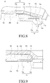
- FIGS. 8 and 9 are views showing a section taken along line A-A' of FIG. 2 and are views showing another embodiment of a first sealing member according to various embodiments of the present disclosure.
- the first sealing member 13 may include a first sealing part 13a and a second sealing part 13b.
- the first sealing part 13a may be mounted to the mounting surface 12c to cover a gap between the body 11 and the cover 12.
- the second sealing part 13b may extend from the first sealing part 13a to seal a gap generated between an end of the inner cover 12b and an inner surface of the outer cover 12a while the inner cover 12b and the outer cover 12a are coupled to each other.
- the first sealing member 13, according to the embodiment of the present disclosure illustrated in FIG. 7 does not include the first sealing part 13a.
- the first sealing member 13, according to the embodiment of the present disclosure illustrated in FIGS. 8 and 9 is provided with both the first sealing part 13a and the second sealing part 13b extending from the first sealing part 13a.
- the first sealing member 13 including only the first sealing part 13a may seal a gap between the cover 12 and the body 11. Furthermore, the first sealing member 13 including the first sealing part 13a and the second sealing part 13b may seal a gap between the cover 12 and the body 11 and also seal a gap between the inner cover 12b and the outer cover 12a.
- the first sealing member 13 discussed in the above described embodiments of the present disclosure includes a closed curve-shaped resilient material, and protrudes toward the sealing surface 11b while being coupled to the mounting surface 12c. If the cover 12 is engaged with a rear surface of the body 11 to cover the rear case 11a, the first sealing member 13 of a resilient material is pressed by and attached to the sealing surface 11b so that a submersion path, that is, a gap between the rear case 11a and the cover 12 or a gap between the inner cover 12b and the outer cover 12a, may be blocked.
- the first sealing member 13 may be coupled to the mounting surface 12c by the coupling member 14.
- the coupling member 14 includes a double-sided tape.
- a configuration of the coupling member 14 is not limited to the double-sided tape.
- the first sealing member 13 of a resilient material may be dually injection-molded into the mounting surface 12c of the cover 12, the first sealing member 13 may be coupled to the mounting surface 12c, however, a configuration of coupling the first sealing member 13 to the mounting surface 12c may be arbitrarily modified or changed.
- the first sealing member 13 of a resilient material may be attached and coupled to the mounting surface 12c through a high temperature and/or a high pressure operation.
- the second sealing member 15 may seal the inner space S2 between the outer cover 12a and the inner cover 12b.
- the cover 12 according to an embodiment of the present disclosure, has a structure of a cover assembly 12 in which the inner cover 12b and the outer cover 12a are stacked so as to be coupled to each other while being attached to each other, such that the cover 12 may include the electronic module EM having a function separately from the body 11. Accordingly, when the inner cover 12b and the outer cover 12a are stacked so as to be coupled, a gap may be generated between the inner cover 12b and the outer cover 12a and moisture and/or foreign substances may be introduced into the inner space S2 through the gap.
- the second sealing member 15 is provided between the inner cover 12b and the outer cover 12a along a circumference of the inner space S2 to seal the inner space S2 from the outside.
- the second sealing member 15, according to an embodiment of the present disclosure, may include at least one of an adhesive, a waterproof tape, and a rubber member to seal a gap between the inner cover 12b and the outer cover 12a after the inner cover 12b and the outer cover 12a are coupled to each other.
- FIG. 10 is a view showing a section taken along line B-B' of FIG. 2 according to an embodiment of the present disclosure.
- the auxiliary coupling unit 22 may be provided on the inner surface of the inner cover 12b and the rear case 11a.
- a battery module BM may be disposed between the inner cover 12b and the outer cover 12a in the space S2.
- the auxiliary coupling unit 22 couples a portion of the cover 12, which becomes farther from the body 11, to the rear case 11a through the first sealing member 13.
- the cover 12 is coupled to a rear surface of the rear case 11a then the first sealing member 13 is attached to the sealing surface 11b, however, a force that pushes the cover 12 in an opposite direction of the body 11 is applied to the cover 12 while the first sealing member 13 is attached to the sealing surface 11b.
- portions of the cover 12, other than the peripheral circumference of an end of the cover 12, coupled to the rear case 11a may fail to maintain their original shapes and are deformed in a direction in which the portions of the cover 12 become farther away from the rear case 11a.
- the auxiliary coupling unit 22 may prevent the cover 12 from being deformed in a direction in which the cover 12 becomes farther away from one surface of the rear case 11a through a resilient force of the first sealing member 13 to make a coupling force firmer.
- the auxiliary coupling unit 22 may be provided in a direction in which the cover 12 is separated from the body 11.
- the cover 12 is bent from one side to an opposite side and the coupling bosses 21b are separated from the coupling recesses 21a. Accordingly, the cover 12 may be coupled to or released from the body 11 in the separation direction of the cover 12 such that the auxiliary coupling unit 22 is separated along the releasing direction when the cover 12 is separated from the body 11 while being bent from one side to an opposite side of the body 11.
- the auxiliary coupling unit 22 may include the recessed parts 22a and the catching parts 22b.
- the recessed parts 22a may be formed between the space S1 of the rear case 11a and the sealing surface 11b.
- the catching parts 22b protruding from an inner surface of the inner cover 12, for example, the hooks (see FIG. 10 ) or the catching balls (see FIG. 11 ), may be caught by or released from the recessed parts 22a. That is, as the catching parts 22b are caught by and fixed to the recessed parts 22a, the cover 12 may be further attached and coupled to the rear case 11a.
- the catching parts 22b may be catching hooks protruding from the inner side of the inner cover 12b toward the recessed parts 22a. As discussed above, the catching hooks are located on the inner surface of the inner cover 11b, and are located on the inner side of the mounting surface 12c. The catching hooks 22b are provided to be opposite to the locations of the recessed parts 22a and are provided to be positioned in the recessed parts 22a. The catching hooks may be formed to be bent in a direction along which the cover 12 is separated. In detail, the catching hooks may be bent from one side to an opposite side of the cover 12 having the finger extraction recess 25.
- a force is applied from one side of the body 11 to an opposite side of the body 11, and the cover 12 is bent from one side of the body 11 to an opposite side of the body 11.
- the catching hooks are bent in the separation direction of the cover 12, they may be separated while being spaced apart from the recessed parts 22a in a direction in which the cover 12 is bent when the cover 12 is separated from the rear case 11a while being coupled to the rear case 11a.
- FIG. 11 is a view showing a section taken along line B-B' of FIG. 2 , and is a view showing another embodiment of a catching part according to an embodiment of the present disclosure.
- the electronic device has the substantially same configuration as the above-described configuration, but the shapes of catching parts thereof are different.
- the description of the configuration of the above-described embodiment will be applied to the present embodiment.
- the catching parts 22b may be catching balls.
- the catching balls protrude toward the recessed parts 22a on the mounting surface 12c, and ends of the catching balls have the shapes of balls.
- the ends of the ball shapes are larger than the recessed parts 22a, and are sized to be large enough to be inserted into or extracted from the recessed parts 22a.
- the catching balls may be formed of a resilient material. If the catching balls larger than the recessed parts 22a are introduced into the recessed parts 22a, they may be introduced into and coupled to the recessed parts 22a while the shapes of the catching balls resiliently vary. If the cover 12 is separated from the rear case 11a, it may be separated from the recessed parts 22a while the shapes of the catching balls resiliently vary.
- the auxiliary coupling unit 22 includes the catching parts 22b and the recessed parts 22a.
- one or more of the catching parts 22b provided on the inner surface of the cover 12 and configured on the inner side of the first sealing member 13 to couple the cover 12 to the body 12, correspond to the recessed parts 22a.
- the recessed parts 22a are provided on one surface of the body 11 to be engaged with the catching parts 22b, the catching parts 22b are detachably disposed on the body, and the catching parts 22b are formed around the space S1 correspond to the recessed parts 22a.
- the auxiliary coupling unit 22, that is, the catching parts 22b and the recessed parts 22a are not limited thereto. That is, the shape and configuration of the auxiliary coupling unit 22 may be variously modified or changed.
- the first fastening parts may correspond to recessed parts and the second fastening parts may correspond to catching parts.
- the electronic device is provided such that a gap generated through coupling, for example, a gap between the cover and the rear case or a gap between the inner cover and the outer cover of the cover assembly 12 may be sealed, so that introduction of foreign substances into the electronic device through the gap can be prevented.
- a gap generated through coupling for example, a gap between the cover and the rear case or a gap between the inner cover and the outer cover of the cover assembly 12 may be sealed, so that introduction of foreign substances into the electronic device through the gap can be prevented.
Landscapes
- Engineering & Computer Science (AREA)
- Computer Hardware Design (AREA)
- Theoretical Computer Science (AREA)
- General Engineering & Computer Science (AREA)
- Microelectronics & Electronic Packaging (AREA)
- Human Computer Interaction (AREA)
- Physics & Mathematics (AREA)
- General Physics & Mathematics (AREA)
- Signal Processing (AREA)
- Power Engineering (AREA)
- Casings For Electric Apparatus (AREA)
- Telephone Set Structure (AREA)
Claims (13)
- Dispositif électronique comprenant :un corps (11) configuré pour loger le dispositif électronique et comprenant un espace pour accueillir une batterie sur une surface du corps (11) ; etun couvercle (12) configuré pour recouvrir au moins l'espace et étant attaché, de manière détachable, au corps (11),dans lequel le couvercle (12) comprend :un premier organe d'étanchéité (13) situé entre la surface du corps (11) et une surface intérieure du couvercle (12) et formé pour entourer l'espace ;dans lequel le couvercle (12) comprend en outre :un couvercle extérieur (12a) ;un couvercle intérieur (12b) situé entre le couvercle extérieur (12a) et le corps (11) lorsque le couvercle (12) est attaché au corps (11) ;un module électronique, dans lequel au moins une portion du module électronique est insérée entre le couvercle extérieur (12a) et le couvercle intérieur (12b) ; etle premier organe d'étanchéité couplé à une surface intérieure du couvercle intérieur.
- Dispositif électronique selon la revendication 1, dans lequel le module électronique comprend au moins l'un d'un chargeur sans fil, d'un chargeur solaire, d'une unité d'antenne, d'un module de communication, d'un processeur, d'un composant de communication en champ proche, NFC, d'une batterie, d'une unité d'identification de radiofréquences, RFID, d'un composant d'émission de chaleur, d'un capteur, d'un affichage, d'une caméra, d'un flash, d'un bouton électrique, d'une unité acoustique et d'un connecteur électrique.
- Dispositif électronique selon la revendication 1, comprenant en outre un deuxième organe d'étanchéité (15) configuré pour entourer le module électronique,
dans lequel le deuxième organe d'étanchéité (15) est situé entre le couvercle extérieur (12a) et le couvercle intérieur (12b). - Dispositif électronique selon la revendication 3, dans lequel le deuxième organe d'étanchéité (15) comprend au moins l'un d'un adhésif, d'un ruban imperméable et d'un organe de caoutchouc.
- Dispositif électronique selon la revendication 1, dans lequel le premier organe d'étanchéité (13) comprend :une première partie d'étanchéité (13a) configurée pour recouvrir un espacement entre le corps (11) et le couvercle (12) ; etune deuxième partie d'étanchéité (13b) s'étendant depuis la première partie d'étanchéité (13a) et configurée pour sceller un espacement entre une extrémité du couvercle intérieur (12b) et une surface intérieure du couvercle extérieur (12a).
- Dispositif électronique selon la revendication 1, comprenant en outre une unité d'étanchéité auxiliaire de type à film mince (13c) s'étendant depuis le premier organe d'étanchéité (13), bloquant un espacement généré entre une surface d'étanchéité (11b) du corps (11) et le premier organe d'étanchéité (13),
dans lequel l'unité d'étanchéité auxiliaire de type à film mince (13c) est disposée entre la surface d'étanchéité (11b) et le premier organe d'étanchéité (13) . - Dispositif électronique selon la revendication 1, dans lequel le premier organe d'étanchéité (13) présente une forme de courbe fermée.
- Dispositif électronique selon la revendication 7, dans lequel le premier organe d'étanchéité (13) est disposé sur une surface d'étanchéité (11b) du corps (11), et
dans lequel la surface d'étanchéité est prévue à une circonférence périphérique de l'espace et est formée dans une forme de courbe fermée sur la base de la circonférence périphérique de l'espace. - Dispositif électronique selon la revendication 1, comprenant en outre :une unité de couplage (21) configurée pour coupler le couvercle (12) à une surface du corps (11) prévue le long d'une circonférence périphérique du couvercle (12) et d'une circonférence périphérique d'un boîtier arrière, etune unité de couplage auxiliaire (22) configurée pour coupler le couvercle (12) à la surface du corps (11) entre l'espace et l'organe d'étanchéité.
- Dispositif électronique selon la revendication 9, dans lequel l'unité de couplage auxiliaire (22) comprend :au moins une première partie de fixation (22b) configurée pour coupler le couvercle (12) au corps (11) et prévue sur une surface intérieure du couvercle (12) et sur un intérieur du premier organe d'étanchéité (13) ; etau moins une deuxième partie de fixation (22a) configurée pour se mettre en prise avec les premières parties de fixation (22b) sur la surface du corps (11),dans lequel l'au moins une deuxième partie de fixation (22a) est disposée de sorte que les premières parties de fixation (22b) soient fixées, de manière détachable, aux deuxièmes parties de fixation (22a), etdans lequel l'au moins une deuxième partie de fixation (22a) est formée autour de l'espace.
- Dispositif électronique selon la revendication 10,
dans lequel l'au moins une première partie de fixation (22b) est une partie d'accrochage prévue sur une surface intérieure du couvercle (12), et
dans lequel l'au moins une deuxième partie de fixation (22a) est une partie évidée par laquelle la partie d'accrochage (22b) est accrochée ou de laquelle la partie d'accrochage (22b) est libérée. - Dispositif électronique selon la revendication 11,
dans lequel la partie d'accrochage (22b) est un crochet d'accrochage qui est plié dans un sens dans lequel le couvercle (12) est séparé. - Dispositif électronique selon la revendication 11,
dans lequel la partie d'accrochage (22b) est une bille d'accrochage constituée d'un matériau élastique.
Applications Claiming Priority (1)
| Application Number | Priority Date | Filing Date | Title |
|---|---|---|---|
| KR1020140020939A KR102246134B1 (ko) | 2014-02-21 | 2014-02-21 | 전자 장치 및 전자 장치 보호 커버 |
Publications (2)
| Publication Number | Publication Date |
|---|---|
| EP2911032A1 EP2911032A1 (fr) | 2015-08-26 |
| EP2911032B1 true EP2911032B1 (fr) | 2018-12-19 |
Family
ID=52596760
Family Applications (1)
| Application Number | Title | Priority Date | Filing Date |
|---|---|---|---|
| EP15155954.9A Not-in-force EP2911032B1 (fr) | 2014-02-21 | 2015-02-20 | Dispositif électronique et son capot de protection |
Country Status (3)
| Country | Link |
|---|---|
| US (1) | US9560783B2 (fr) |
| EP (1) | EP2911032B1 (fr) |
| KR (1) | KR102246134B1 (fr) |
Families Citing this family (29)
| Publication number | Priority date | Publication date | Assignee | Title |
|---|---|---|---|---|
| USD777716S1 (en) * | 2015-02-19 | 2017-01-31 | Spigen Korea Co., Ltd. | Case for electronic devices |
| USD806060S1 (en) | 2015-02-23 | 2017-12-26 | Spigen Korea Co., Ltd. | Case for electronic devices |
| USD780164S1 (en) * | 2015-02-23 | 2017-02-28 | Spigen Korea Co., Ltd. | Case for electronic device |
| USD780165S1 (en) * | 2015-02-23 | 2017-02-28 | Spigen Korea Co., Ltd. | Case for electronic device |
| USD823290S1 (en) * | 2015-02-23 | 2018-07-17 | Spigen Korea Co., Ltd. | Case for electronic devices |
| JP2016213567A (ja) | 2015-04-30 | 2016-12-15 | アイコム株式会社 | 電子機器及び電子機器の制御方法 |
| JP6447346B2 (ja) * | 2015-04-30 | 2019-01-09 | アイコム株式会社 | 電子機器及び電子機器の制御方法 |
| KR102514770B1 (ko) * | 2015-10-02 | 2023-03-29 | 삼성전자주식회사 | 방수 구조를 포함하는 전자 장치 |
| US9872408B2 (en) | 2015-10-02 | 2018-01-16 | Samsung Electronics Co., Ltd. | Electronic device including waterproof structure |
| USD831633S1 (en) | 2016-08-19 | 2018-10-23 | Spigen Korea Co., Ltd. | Case for electronic communications device |
| USD902905S1 (en) | 2016-08-19 | 2020-11-24 | Spigen Korea Co., Ltd. | Case for electronic communications device |
| USD902906S1 (en) | 2016-08-19 | 2020-11-24 | Spigen Korea Co., Ltd. | Case for electronic communications device |
| JP6663595B2 (ja) * | 2017-09-13 | 2020-03-13 | カシオ計算機株式会社 | 電池蓋構造および携帯端末 |
| USD857000S1 (en) | 2018-01-08 | 2019-08-20 | Spigen Korea Co., Ltd. | Case for electronic communications device |
| USD857684S1 (en) | 2018-01-08 | 2019-08-27 | Spigen Korea Co., Ltd. | Case for electronic communications device |
| USD856999S1 (en) | 2018-01-08 | 2019-08-20 | Spigen Korea Co., Ltd. | Case for electronic communications device |
| USD860187S1 (en) | 2018-07-18 | 2019-09-17 | Spigen Korea Co., Ltd. | Case for electronic communications device |
| USD860188S1 (en) | 2018-07-19 | 2019-09-17 | Spigen Korea Co., Ltd. | Case for electronic communications device |
| USD857686S1 (en) | 2018-07-20 | 2019-08-27 | Spigen Korea Co., Ltd. | Case for electronic communications device |
| USD890738S1 (en) | 2019-01-10 | 2020-07-21 | Spigen Korea Co., Ltd. | Case for electronic communications device |
| USD879764S1 (en) * | 2019-02-27 | 2020-03-31 | Spigen Korea Co., Ltd. | Case for electronic communications device |
| USD899412S1 (en) | 2019-03-18 | 2020-10-20 | Spigen Korea Co., Ltd. | Case for electronic communications device |
| KR102679883B1 (ko) * | 2019-04-30 | 2024-07-01 | 삼성전자 주식회사 | 전자부품의 방수구조를 갖는 전자장치 |
| KR20210009641A (ko) * | 2019-07-17 | 2021-01-27 | 삼성전자주식회사 | 복합 시트 및 이를 포함하는 전자 장치 |
| KR102727436B1 (ko) | 2019-07-29 | 2024-11-06 | 삼성전자주식회사 | 솔리드 스테이트 드라이브 장치 |
| USD934223S1 (en) | 2019-08-22 | 2021-10-26 | Spigen Korea Co., Ltd. | Case for electronic communications device |
| USD910004S1 (en) | 2020-03-20 | 2021-02-09 | Spigen Korea Co., Ltd. | Case for electronic communications device |
| CN113315861B (zh) * | 2021-06-11 | 2024-04-19 | 维沃移动通信有限公司 | 电子设备 |
| CN116981207A (zh) | 2022-04-22 | 2023-10-31 | 台达电子工业股份有限公司 | 电子装置 |
Family Cites Families (16)
| Publication number | Priority date | Publication date | Assignee | Title |
|---|---|---|---|---|
| SE515918C2 (sv) * | 1999-03-15 | 2001-10-29 | Ericsson Telefon Ab L M | Utbytbar panel hos en mobilradiostation, främre del för ett hus hos en mobilradiostation, mobilradiostation samt sätt för att bortagbart fästa den utbytbara panelen vid en mobilradiostation |
| JP2007258877A (ja) * | 2006-03-22 | 2007-10-04 | Tokai Rika Co Ltd | 携帯機 |
| US8068331B2 (en) * | 2006-09-06 | 2011-11-29 | Roche Diagnostics Operations, Inc. | Enclosure to prevent fluid ingress of a device having a touch screen interface |
| JP5457226B2 (ja) * | 2010-02-26 | 2014-04-02 | 富士通株式会社 | シール構造、電子装置、携帯装置及びシール方法 |
| US8792249B2 (en) * | 2010-05-14 | 2014-07-29 | Sony Corporation | Waterproofing structure of mobile terminal and mobile terminal including the same |
| CN102263208B (zh) | 2010-05-31 | 2013-09-25 | 国基电子(上海)有限公司 | 便携式移动终端 |
| KR20120041604A (ko) * | 2010-10-21 | 2012-05-02 | (주) 캐치웰 | 모바일 단말기의 배터리 조립체 |
| JP2012095152A (ja) | 2010-10-27 | 2012-05-17 | Nec Corp | 携帯電子機器 |
| JP5472125B2 (ja) * | 2011-01-07 | 2014-04-16 | カシオ計算機株式会社 | 携帯機器 |
| US20120162881A1 (en) * | 2010-12-22 | 2012-06-28 | Casio Computer Co., Ltd. | Mobile device |
| WO2013080669A1 (fr) * | 2011-11-28 | 2013-06-06 | Necカシオモバイルコミュニケーションズ株式会社 | Structure anti-poussière et dispositif électronique |
| US8770402B2 (en) | 2012-01-26 | 2014-07-08 | Iceberg Commerce Inc. | Waterproof protective case for a mobile device |
| KR200461453Y1 (ko) * | 2012-01-31 | 2012-07-12 | 박정식 | 투시창을 갖는 모바일 단말기 케이스 |
| KR101892030B1 (ko) | 2012-03-21 | 2018-08-29 | 삼성전자주식회사 | 휴대 단말기의 배터리 커버 방수 장치 |
| KR101580518B1 (ko) | 2012-04-05 | 2015-12-28 | 엘지전자 주식회사 | 안테나 및 이를 구비한 이동 단말기 |
| KR101929879B1 (ko) * | 2012-04-09 | 2019-03-15 | 삼성전자주식회사 | 휴대 단말기 |
-
2014
- 2014-02-21 KR KR1020140020939A patent/KR102246134B1/ko not_active Expired - Fee Related
-
2015
- 2015-02-13 US US14/622,090 patent/US9560783B2/en active Active
- 2015-02-20 EP EP15155954.9A patent/EP2911032B1/fr not_active Not-in-force
Non-Patent Citations (1)
| Title |
|---|
| None * |
Also Published As
| Publication number | Publication date |
|---|---|
| EP2911032A1 (fr) | 2015-08-26 |
| KR102246134B1 (ko) | 2021-04-29 |
| US9560783B2 (en) | 2017-01-31 |
| KR20150099326A (ko) | 2015-08-31 |
| US20150245522A1 (en) | 2015-08-27 |
Similar Documents
| Publication | Publication Date | Title |
|---|---|---|
| EP2911032B1 (fr) | Dispositif électronique et son capot de protection | |
| KR102308940B1 (ko) | 방수 구조를 포함하는 전자 장치 | |
| KR102613138B1 (ko) | 센서 키 조립체의 방수 구조를 포함하는 전자 장치 | |
| CN104979630B (zh) | 天线模块及包括该天线模块的电子装置 | |
| KR102348755B1 (ko) | 트레이, 트레이 분리용 지그 및 그것을 포함하는 전자 장치 | |
| US10171896B2 (en) | Electronic device with side speaker hole | |
| KR102497472B1 (ko) | 방수 구조를 포함하는 전자 장치 | |
| EP3136693B1 (fr) | Dispositif électronique comportant une structure étanche à l'eau | |
| CN110140340B (zh) | 电池的保护电路模块外壳及包括所述外壳的电子装置 | |
| KR102207162B1 (ko) | 카메라 장치 및 카메라 장치를 구비한 전자 장치 | |
| EP2911033B1 (fr) | Dispositif de protection de matériel et dispositifs électroniques comprenant ceux-ci | |
| US10109946B2 (en) | Sealed circuit board connectors and electronic device including same | |
| US10911848B2 (en) | Sound component with sealing member and electronic device with the same | |
| US10686920B2 (en) | Mobile terminal | |
| US20160360632A1 (en) | Electronic device | |
| US20240280943A1 (en) | Electronic device comprising speaker structure | |
| EP3509278A1 (fr) | Composant électronique, et dispositif électronique le comprenant | |
| CN107809570A (zh) | 具有防水摄像头的智能穿戴设备 | |
| EP2908508B1 (fr) | Dispositif électronique comportant une ouverture | |
| KR102219839B1 (ko) | 전자 장치용 커버 디바이스 | |
| JP2014093611A (ja) | 電子機器 | |
| US12348930B2 (en) | Electronic apparatus | |
| CN107250926B (zh) | 电子设备 | |
| KR20130010803A (ko) | 이동 단말기 |
Legal Events
| Date | Code | Title | Description |
|---|---|---|---|
| PUAI | Public reference made under article 153(3) epc to a published international application that has entered the european phase |
Free format text: ORIGINAL CODE: 0009012 |
|
| AK | Designated contracting states |
Kind code of ref document: A1 Designated state(s): AL AT BE BG CH CY CZ DE DK EE ES FI FR GB GR HR HU IE IS IT LI LT LU LV MC MK MT NL NO PL PT RO RS SE SI SK SM TR |
|
| AX | Request for extension of the european patent |
Extension state: BA ME |
|
| 17P | Request for examination filed |
Effective date: 20160226 |
|
| RBV | Designated contracting states (corrected) |
Designated state(s): AL AT BE BG CH CY CZ DE DK EE ES FI FR GB GR HR HU IE IS IT LI LT LU LV MC MK MT NL NO PL PT RO RS SE SI SK SM TR |
|
| STAA | Information on the status of an ep patent application or granted ep patent |
Free format text: STATUS: EXAMINATION IS IN PROGRESS |
|
| 17Q | First examination report despatched |
Effective date: 20171024 |
|
| GRAP | Despatch of communication of intention to grant a patent |
Free format text: ORIGINAL CODE: EPIDOSNIGR1 |
|
| STAA | Information on the status of an ep patent application or granted ep patent |
Free format text: STATUS: GRANT OF PATENT IS INTENDED |
|
| INTG | Intention to grant announced |
Effective date: 20180704 |
|
| GRAS | Grant fee paid |
Free format text: ORIGINAL CODE: EPIDOSNIGR3 |
|
| GRAA | (expected) grant |
Free format text: ORIGINAL CODE: 0009210 |
|
| STAA | Information on the status of an ep patent application or granted ep patent |
Free format text: STATUS: THE PATENT HAS BEEN GRANTED |
|
| AK | Designated contracting states |
Kind code of ref document: B1 Designated state(s): AL AT BE BG CH CY CZ DE DK EE ES FI FR GB GR HR HU IE IS IT LI LT LU LV MC MK MT NL NO PL PT RO RS SE SI SK SM TR |
|
| REG | Reference to a national code |
Ref country code: GB Ref legal event code: FG4D |
|
| REG | Reference to a national code |
Ref country code: CH Ref legal event code: EP |
|
| REG | Reference to a national code |
Ref country code: IE Ref legal event code: FG4D |
|
| REG | Reference to a national code |
Ref country code: DE Ref legal event code: R096 Ref document number: 602015021736 Country of ref document: DE |
|
| REG | Reference to a national code |
Ref country code: AT Ref legal event code: REF Ref document number: 1079361 Country of ref document: AT Kind code of ref document: T Effective date: 20190115 |
|
| REG | Reference to a national code |
Ref country code: NL Ref legal event code: FP |
|
| PG25 | Lapsed in a contracting state [announced via postgrant information from national office to epo] |
Ref country code: LV Free format text: LAPSE BECAUSE OF FAILURE TO SUBMIT A TRANSLATION OF THE DESCRIPTION OR TO PAY THE FEE WITHIN THE PRESCRIBED TIME-LIMIT Effective date: 20181219 Ref country code: HR Free format text: LAPSE BECAUSE OF FAILURE TO SUBMIT A TRANSLATION OF THE DESCRIPTION OR TO PAY THE FEE WITHIN THE PRESCRIBED TIME-LIMIT Effective date: 20181219 Ref country code: NO Free format text: LAPSE BECAUSE OF FAILURE TO SUBMIT A TRANSLATION OF THE DESCRIPTION OR TO PAY THE FEE WITHIN THE PRESCRIBED TIME-LIMIT Effective date: 20190319 Ref country code: BG Free format text: LAPSE BECAUSE OF FAILURE TO SUBMIT A TRANSLATION OF THE DESCRIPTION OR TO PAY THE FEE WITHIN THE PRESCRIBED TIME-LIMIT Effective date: 20190319 Ref country code: LT Free format text: LAPSE BECAUSE OF FAILURE TO SUBMIT A TRANSLATION OF THE DESCRIPTION OR TO PAY THE FEE WITHIN THE PRESCRIBED TIME-LIMIT Effective date: 20181219 Ref country code: FI Free format text: LAPSE BECAUSE OF FAILURE TO SUBMIT A TRANSLATION OF THE DESCRIPTION OR TO PAY THE FEE WITHIN THE PRESCRIBED TIME-LIMIT Effective date: 20181219 |
|
| REG | Reference to a national code |
Ref country code: LT Ref legal event code: MG4D |
|
| REG | Reference to a national code |
Ref country code: AT Ref legal event code: MK05 Ref document number: 1079361 Country of ref document: AT Kind code of ref document: T Effective date: 20181219 |
|
| PG25 | Lapsed in a contracting state [announced via postgrant information from national office to epo] |
Ref country code: SE Free format text: LAPSE BECAUSE OF FAILURE TO SUBMIT A TRANSLATION OF THE DESCRIPTION OR TO PAY THE FEE WITHIN THE PRESCRIBED TIME-LIMIT Effective date: 20181219 Ref country code: RS Free format text: LAPSE BECAUSE OF FAILURE TO SUBMIT A TRANSLATION OF THE DESCRIPTION OR TO PAY THE FEE WITHIN THE PRESCRIBED TIME-LIMIT Effective date: 20181219 Ref country code: AL Free format text: LAPSE BECAUSE OF FAILURE TO SUBMIT A TRANSLATION OF THE DESCRIPTION OR TO PAY THE FEE WITHIN THE PRESCRIBED TIME-LIMIT Effective date: 20181219 Ref country code: GR Free format text: LAPSE BECAUSE OF FAILURE TO SUBMIT A TRANSLATION OF THE DESCRIPTION OR TO PAY THE FEE WITHIN THE PRESCRIBED TIME-LIMIT Effective date: 20190320 |
|
| PG25 | Lapsed in a contracting state [announced via postgrant information from national office to epo] |
Ref country code: PT Free format text: LAPSE BECAUSE OF FAILURE TO SUBMIT A TRANSLATION OF THE DESCRIPTION OR TO PAY THE FEE WITHIN THE PRESCRIBED TIME-LIMIT Effective date: 20190419 Ref country code: ES Free format text: LAPSE BECAUSE OF FAILURE TO SUBMIT A TRANSLATION OF THE DESCRIPTION OR TO PAY THE FEE WITHIN THE PRESCRIBED TIME-LIMIT Effective date: 20181219 Ref country code: CZ Free format text: LAPSE BECAUSE OF FAILURE TO SUBMIT A TRANSLATION OF THE DESCRIPTION OR TO PAY THE FEE WITHIN THE PRESCRIBED TIME-LIMIT Effective date: 20181219 Ref country code: IT Free format text: LAPSE BECAUSE OF FAILURE TO SUBMIT A TRANSLATION OF THE DESCRIPTION OR TO PAY THE FEE WITHIN THE PRESCRIBED TIME-LIMIT Effective date: 20181219 Ref country code: PL Free format text: LAPSE BECAUSE OF FAILURE TO SUBMIT A TRANSLATION OF THE DESCRIPTION OR TO PAY THE FEE WITHIN THE PRESCRIBED TIME-LIMIT Effective date: 20181219 |
|
| PG25 | Lapsed in a contracting state [announced via postgrant information from national office to epo] |
Ref country code: IS Free format text: LAPSE BECAUSE OF FAILURE TO SUBMIT A TRANSLATION OF THE DESCRIPTION OR TO PAY THE FEE WITHIN THE PRESCRIBED TIME-LIMIT Effective date: 20190419 Ref country code: SK Free format text: LAPSE BECAUSE OF FAILURE TO SUBMIT A TRANSLATION OF THE DESCRIPTION OR TO PAY THE FEE WITHIN THE PRESCRIBED TIME-LIMIT Effective date: 20181219 Ref country code: EE Free format text: LAPSE BECAUSE OF FAILURE TO SUBMIT A TRANSLATION OF THE DESCRIPTION OR TO PAY THE FEE WITHIN THE PRESCRIBED TIME-LIMIT Effective date: 20181219 Ref country code: RO Free format text: LAPSE BECAUSE OF FAILURE TO SUBMIT A TRANSLATION OF THE DESCRIPTION OR TO PAY THE FEE WITHIN THE PRESCRIBED TIME-LIMIT Effective date: 20181219 Ref country code: SM Free format text: LAPSE BECAUSE OF FAILURE TO SUBMIT A TRANSLATION OF THE DESCRIPTION OR TO PAY THE FEE WITHIN THE PRESCRIBED TIME-LIMIT Effective date: 20181219 |
|
| REG | Reference to a national code |
Ref country code: DE Ref legal event code: R097 Ref document number: 602015021736 Country of ref document: DE |
|
| REG | Reference to a national code |
Ref country code: CH Ref legal event code: PL |
|
| PLBE | No opposition filed within time limit |
Free format text: ORIGINAL CODE: 0009261 |
|
| STAA | Information on the status of an ep patent application or granted ep patent |
Free format text: STATUS: NO OPPOSITION FILED WITHIN TIME LIMIT |
|
| PG25 | Lapsed in a contracting state [announced via postgrant information from national office to epo] |
Ref country code: LU Free format text: LAPSE BECAUSE OF NON-PAYMENT OF DUE FEES Effective date: 20190220 Ref country code: MC Free format text: LAPSE BECAUSE OF FAILURE TO SUBMIT A TRANSLATION OF THE DESCRIPTION OR TO PAY THE FEE WITHIN THE PRESCRIBED TIME-LIMIT Effective date: 20181219 Ref country code: AT Free format text: LAPSE BECAUSE OF FAILURE TO SUBMIT A TRANSLATION OF THE DESCRIPTION OR TO PAY THE FEE WITHIN THE PRESCRIBED TIME-LIMIT Effective date: 20181219 Ref country code: DK Free format text: LAPSE BECAUSE OF FAILURE TO SUBMIT A TRANSLATION OF THE DESCRIPTION OR TO PAY THE FEE WITHIN THE PRESCRIBED TIME-LIMIT Effective date: 20181219 |
|
| REG | Reference to a national code |
Ref country code: BE Ref legal event code: MM Effective date: 20190228 |
|
| 26N | No opposition filed |
Effective date: 20190920 |
|
| REG | Reference to a national code |
Ref country code: IE Ref legal event code: MM4A |
|
| PG25 | Lapsed in a contracting state [announced via postgrant information from national office to epo] |
Ref country code: LI Free format text: LAPSE BECAUSE OF NON-PAYMENT OF DUE FEES Effective date: 20190228 Ref country code: CH Free format text: LAPSE BECAUSE OF NON-PAYMENT OF DUE FEES Effective date: 20190228 |
|
| PG25 | Lapsed in a contracting state [announced via postgrant information from national office to epo] |
Ref country code: IE Free format text: LAPSE BECAUSE OF NON-PAYMENT OF DUE FEES Effective date: 20190220 |
|
| PG25 | Lapsed in a contracting state [announced via postgrant information from national office to epo] |
Ref country code: SI Free format text: LAPSE BECAUSE OF FAILURE TO SUBMIT A TRANSLATION OF THE DESCRIPTION OR TO PAY THE FEE WITHIN THE PRESCRIBED TIME-LIMIT Effective date: 20181219 Ref country code: BE Free format text: LAPSE BECAUSE OF NON-PAYMENT OF DUE FEES Effective date: 20190228 Ref country code: FR Free format text: LAPSE BECAUSE OF NON-PAYMENT OF DUE FEES Effective date: 20190228 |
|
| PG25 | Lapsed in a contracting state [announced via postgrant information from national office to epo] |
Ref country code: TR Free format text: LAPSE BECAUSE OF FAILURE TO SUBMIT A TRANSLATION OF THE DESCRIPTION OR TO PAY THE FEE WITHIN THE PRESCRIBED TIME-LIMIT Effective date: 20181219 |
|
| PG25 | Lapsed in a contracting state [announced via postgrant information from national office to epo] |
Ref country code: MT Free format text: LAPSE BECAUSE OF NON-PAYMENT OF DUE FEES Effective date: 20190220 |
|
| PGFP | Annual fee paid to national office [announced via postgrant information from national office to epo] |
Ref country code: NL Payment date: 20210121 Year of fee payment: 7 |
|
| PG25 | Lapsed in a contracting state [announced via postgrant information from national office to epo] |
Ref country code: CY Free format text: LAPSE BECAUSE OF FAILURE TO SUBMIT A TRANSLATION OF THE DESCRIPTION OR TO PAY THE FEE WITHIN THE PRESCRIBED TIME-LIMIT Effective date: 20181219 |
|
| PGFP | Annual fee paid to national office [announced via postgrant information from national office to epo] |
Ref country code: DE Payment date: 20210120 Year of fee payment: 7 Ref country code: GB Payment date: 20210122 Year of fee payment: 7 |
|
| PG25 | Lapsed in a contracting state [announced via postgrant information from national office to epo] |
Ref country code: HU Free format text: LAPSE BECAUSE OF FAILURE TO SUBMIT A TRANSLATION OF THE DESCRIPTION OR TO PAY THE FEE WITHIN THE PRESCRIBED TIME-LIMIT; INVALID AB INITIO Effective date: 20150220 |
|
| PG25 | Lapsed in a contracting state [announced via postgrant information from national office to epo] |
Ref country code: MK Free format text: LAPSE BECAUSE OF FAILURE TO SUBMIT A TRANSLATION OF THE DESCRIPTION OR TO PAY THE FEE WITHIN THE PRESCRIBED TIME-LIMIT Effective date: 20181219 |
|
| REG | Reference to a national code |
Ref country code: DE Ref legal event code: R119 Ref document number: 602015021736 Country of ref document: DE |
|
| REG | Reference to a national code |
Ref country code: NL Ref legal event code: MM Effective date: 20220301 |
|
| GBPC | Gb: european patent ceased through non-payment of renewal fee |
Effective date: 20220220 |
|
| PG25 | Lapsed in a contracting state [announced via postgrant information from national office to epo] |
Ref country code: NL Free format text: LAPSE BECAUSE OF NON-PAYMENT OF DUE FEES Effective date: 20220301 |
|
| PG25 | Lapsed in a contracting state [announced via postgrant information from national office to epo] |
Ref country code: GB Free format text: LAPSE BECAUSE OF NON-PAYMENT OF DUE FEES Effective date: 20220220 Ref country code: DE Free format text: LAPSE BECAUSE OF NON-PAYMENT OF DUE FEES Effective date: 20220901 |