EP2911164B1 - Elektromagnetische Betätigungsvorrichtung - Google Patents
Elektromagnetische Betätigungsvorrichtung Download PDFInfo
- Publication number
- EP2911164B1 EP2911164B1 EP15000334.1A EP15000334A EP2911164B1 EP 2911164 B1 EP2911164 B1 EP 2911164B1 EP 15000334 A EP15000334 A EP 15000334A EP 2911164 B1 EP2911164 B1 EP 2911164B1
- Authority
- EP
- European Patent Office
- Prior art keywords
- armature
- pole core
- shaft
- spring
- compression spring
- Prior art date
- Legal status (The legal status is an assumption and is not a legal conclusion. Google has not performed a legal analysis and makes no representation as to the accuracy of the status listed.)
- Active
Links
- 230000006835 compression Effects 0.000 claims description 16
- 238000007906 compression Methods 0.000 claims description 16
- 238000004804 winding Methods 0.000 claims description 10
- 230000005291 magnetic effect Effects 0.000 claims description 6
- 230000000694 effects Effects 0.000 claims description 2
- 238000004519 manufacturing process Methods 0.000 description 6
- 230000000181 anti-adherent effect Effects 0.000 description 1
- 230000000712 assembly Effects 0.000 description 1
- 238000000429 assembly Methods 0.000 description 1
- 230000005294 ferromagnetic effect Effects 0.000 description 1
- 230000003993 interaction Effects 0.000 description 1
- 230000036316 preload Effects 0.000 description 1
- 238000000926 separation method Methods 0.000 description 1
Images
Classifications
-
- H—ELECTRICITY
- H01—ELECTRIC ELEMENTS
- H01F—MAGNETS; INDUCTANCES; TRANSFORMERS; SELECTION OF MATERIALS FOR THEIR MAGNETIC PROPERTIES
- H01F7/00—Magnets
- H01F7/06—Electromagnets; Actuators including electromagnets
- H01F7/08—Electromagnets; Actuators including electromagnets with armatures
- H01F7/13—Electromagnets; Actuators including electromagnets with armatures characterised by pulling-force characteristics
-
- H—ELECTRICITY
- H01—ELECTRIC ELEMENTS
- H01F—MAGNETS; INDUCTANCES; TRANSFORMERS; SELECTION OF MATERIALS FOR THEIR MAGNETIC PROPERTIES
- H01F7/00—Magnets
- H01F7/06—Electromagnets; Actuators including electromagnets
- H01F7/08—Electromagnets; Actuators including electromagnets with armatures
- H01F7/16—Rectilinearly-movable armatures
- H01F7/1607—Armatures entering the winding
-
- H—ELECTRICITY
- H01—ELECTRIC ELEMENTS
- H01F—MAGNETS; INDUCTANCES; TRANSFORMERS; SELECTION OF MATERIALS FOR THEIR MAGNETIC PROPERTIES
- H01F7/00—Magnets
- H01F7/06—Electromagnets; Actuators including electromagnets
- H01F7/08—Electromagnets; Actuators including electromagnets with armatures
- H01F7/081—Magnetic constructions
- H01F2007/085—Yoke or polar piece between coil bobbin and armature having a gap, e.g. filled with nonmagnetic material
Definitions
- the invention relates to an electromagnetic actuator, in particular proportional magnet or solenoid, having the features in the preamble of claim 1.
- Such electromagnetic actuators are available in a variety of embodiments in the market. In many cases, these devices are provided for actuating valves. In particular, in such an application, the response of the actuator is of particular importance for achieving a safe and desirable function of valves and related systems. More specifically, for certain switching or control functions, a certain curve of the magnetic force-stroke characteristic is required. For the manufacturer of such actuators, this means that it can be adjusted as needed, i. depending on which course of the F-s characteristic curve is required, the actuator must provide the respectively corresponding response or operating behavior. To meet these requirements, a corresponding cost in the production is required.
- the EP 0 464 370 A1 describes an electromagnetic actuator, in particular a proportional solenoid or a solenoid, with a magnet armature which is guided axially movably in a pole tube which is at least partially surrounded by a coil winding and which has a separating region forming a magnetic decoupling and to which a pole core adjoins, a magnetic force acting on the armature when the coil winding is energized, acting against it it tries to move to him acting restoring force in the direction of the pole core, wherein an armature acting on the compression spring is provided, which biases the armature against a fixed end position, from which the armature by energizing the coil winding against the spring force is movable, wherein the adjusting device for the armature opposite end of the compression spring has a support element which is positionally adjustable to a desired spring bias generating axial position, wherein an adjustment is provided by means of which the effect of the restoring force is adjustable to a desired target value, wherein
- the invention has the object to provide an actuator of said genus available, in which a desired response and performance can be achieved with low production costs.
- a significant feature of the invention is that the shaft has a coaxial inner through hole in which a tension member is axially movable, having at one end a driver, the anchor for a retraction movement of the tension member Emergency operation moves against the action of the compression spring.
- the actuating device can be equipped in a particularly rational manner with a device for emergency operation.
- an adjusting device is provided, by means of which the action of the restoring force acting on the armature can be set to a desired desired value. Due to the possibility of modifying the restoring force acting on the armature in the desired manner, the actuating device can be calibrated for a respective desired F-s characteristic curve. Without tight production tolerances would have to be met and without structural changes would be required, this can be a same production batch adapted to different operating requirements, so that a particularly efficient production can be achieved. In particular, the wishes of customers can be met in an economical manner, which require a special course of the force-stroke characteristic even at low quantities.
- an armature engaging compression spring which biases the armature against a predetermined end position from which the armature is movable by energizing the coil winding against the spring force, wherein the adjusting means for the armature opposite end of the compression spring has a support member which on a a desired spring tension generating axial position is position adjustable.
- an external thread on the shaft rotatable in the passage of the pole core and the external thread associated internal thread in the passage of the pole core may be provided, wherein preferably at the projecting from the pole core end of the shaft a point of attachment for a setting rotary tool is formed , For example, an external hexagon or the like for a turning tool.
- a tension member in the form of a rotatable in the through hole of the shank pull rod may be provided which has a cooperating with an internal thread in the through hole external thread to produce a retraction and is accessible at its end remote from the armature for a rotary actuator. An emergency operation is thus carried out in a simple manner by turning the pull rod.
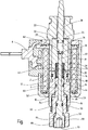
- a coil winding is denoted by 2, which is located on a bobbin 4 and can be supplied with current via an electrical connection device 6.
- the bobbin 4 surrounds a pole tube 8 and a longitudinal portion of a pole core 10, which adjoins the open end of the pole tube 8 lying in the figure below. With this, the pole core 10 is connected in such a way that it engages with its end 14 in the pole tube 8 and is fixed by means of a flanging 12 of the pole tube 8.
- the bobbin 4 with the winding 2 is surrounded by a ferromagnetic pot-shaped magnet housing 16 which is penetrated at the bottom in the figure by an end protruding from the housing 16 end portion 18 of the pole core 10 and is closed at the opposite end by a pole piece 20, which surrounds an end portion 22 protruding from the housing 16, in which the inner end surface 24 of the pole tube 8 is formed.
- a magnet armature 28 is guided axially movable.
- the armature 28 is biased by means of a helical compression spring 30 in an axial end position, which is shown in the figure and in which it rests against an annular disc 32 which is located on the end surface 24 of the pole tube end portion 22. From the end position shown in the figure, the armature 28 is movable by energizing the coil winding 2 against the restoring force of the compression spring 30.
- the annular disc 32 may be formed by a so-called. Anti-adhesive disc.
- the magnet armature 28 has a coaxial passageway formed by three bore sections.
- a rod-like actuator 36 which extends through the end portion 22 and is provided as an actuator for an actuation or control operation, such as a valve actuation.
- the inner end 38 of the bore portion 34 is adjoined by a tapered central bore portion 40, which in turn merges into a lower, enlarged diameter bore portion 42.
- This bore portion 42 forms part of the spring housing for the compression spring 30th
- a coaxial passage is provided, which is also formed by a stepped bore, with an armature 28 facing first bore portion 44, whose diameter to that of the facing Bore portion 42 of the armature 28 corresponds, so that the bore portion 44 in the pole core 10, the spring housing of the compression spring 30 continues.
- the bore portion 44 is adjoined in the pole core 10 by a bore section 48 with its internal thread 50, the section 48 having the internal thread 50 extending to the outer end of the end section 18 of the pole core 10. From the outer end, a shaft 52 is screwed into the passage of the pole core 10, which is part of a device for adjusting the spring action of the compression spring 30.
- the shaft 52 has for this purpose a threaded portion 54 with external thread 56 which can be screwed to the internal thread 50 in the pole core 10.
- the shaft 52 has a tapered, guided in the bore portion 44 of the pole core 10 setting part at the end of an annular disc 46 abuts against which the facing, projecting into the bore portion 44 end of the compression spring 30 is supported.
- the spring preload is thus adjustable by rotational actuation of the shaft 52.
- a coaxial through-hole 58 is formed for a pull rod 60.
- This extends with its inner end through the bore sections 42 and 40 in the armature 28 through into its bore portion 34 into it.
- the end of the pull rod 60 is widened by caulking in such a way that a driver 62 is formed, the armature 28 entrains in a retraction movement of the drawbar 60 which extends downward in the figure, that is moved against the action of the tension spring 30.
- an emergency manual operation of the device can be effected.
- an internal thread 64 for the interaction with an external thread 66 at the end portion 68 of the tie rod 60 is formed in an enlarged end portion of the through hole 58.
- the drawbar 60 by means of a in End portion 68 located hexagon socket 70 is rotatable to produce a retracting movement of the tie rod 60.
Landscapes
- Physics & Mathematics (AREA)
- Electromagnetism (AREA)
- Engineering & Computer Science (AREA)
- Power Engineering (AREA)
- Electromagnets (AREA)
Description
- Die Erfindung betrifft eine elektromagnetische Betätigungsvorrichtung, insbesondere Proportionalmagnet oder Schaltmagnet, mit den Merkmalen im Oberbegriff von Anspruch 1.
- Derartige elektromagnetische Betätigungsvorrichtungen sind in einer Vielzahl von Ausführungsformen auf dem Markt erhältlich. Vielfach sind diese Vorrichtungen zur Betätigung von Ventilen vorgesehen. Insbesondere bei einem derartigen Einsatz ist das Ansprechverhalten der Betätigungsvorrichtung für das Erreichen einer sicheren und gewünschten Funktion betreffender Ventile und zugehöriger Systeme von besonderer Bedeutung. Genauer gesagt, ist für betreffende Schalt- oder Steuerfunktionen ein bestimmter Verlauf der Magnetkraft-Hubweg-Kennlinie erforderlich. Für den Hersteller derartiger Betätigungsvorrichtungen bedeutet dies, dass er je nach Bedarf, d.h. abhängig davon, welcher Verlauf der F-s-Kennlinie erforderlich ist, die Betätigungsvorrichtung mit dem jeweils entsprechenden Ansprech- oder Betriebsverhalten zur Verfügung stellen muss. Um diesen Anforderungen gerecht zu werden, ist ein entsprechender Kostenaufwand bei der Herstellung erforderlich.
- Die
EP 0 464 370 A1 beschreibt eine elektromagnetische Betätigungsvorrichtung, insbesondere einen Proportionalmagneten oder einen Schaltmagneten, mit einem Magnetanker, der in einem von einer Spulenwicklung zumindest teilweise umgebenen Polrohr axial bewegbar geführt ist, das einen eine magnetische Entkopplung bildenden Trennbereich aufweist und an das sich ein Polkern anschließt, wobei bei Bestromung der Spulenwicklung am Anker eine Magnetkraft wirkt, die diesen gegen eine an ihm angreifende Rückstellkraft in Richtung auf den Polkern zu bewegen sucht, wobei eine am Anker angreifende Druckfeder vorgesehen ist, die den Magnetanker gegen eine festgelegte Endposition vorspannt, aus der der Anker durch Bestromen der Spulenwicklung gegen die Federkraft bewegbar ist, wobei die Einstelleinrichtung für das dem Anker entgegengesetzte Ende der Druckfeder ein Abstützelement aufweist, das auf eine eine gewünschte Federvorspannung erzeugende Axialposition lageeinstellbar ist, wobei eine Einstelleinrichtung vorgesehen ist, mittels deren die Wirkung der Rückstellkraft auf einen gewünschten Sollwert einstellbar ist, wobei das dem Magnetanker abgewandte Ende der Druckfeder in einen koaxialen Durchgang im Polkern eingreift und wobei das Abstützelement der Einstelleinrichtung durch das Ende eines Schaftes gebildet ist, der im Durchgang des Polkerns mittels einer Einstellschraubeneinrichtung axial einstellbar geführt ist. Der Schaft ist dabei bohrungsfrei ausgeführt. - Weitere elektromagnetische Betätigungsvorrichtungen gehen aus der
US 2006/0145113 A1 , derUS 4 339 109 , derDE 40 21 623 A1 und derUS 2009/0140189 A1 hervor. - Im Hinblick auf diese Problematik stellt sich die Erfindung die Aufgabe, eine Betätigungsvorrichtung der besagten Gattung zur Verfügung zu stellen, bei der sich ein gewünschtes Ansprech- und Betriebsverhalten mit geringem Fertigungsaufwand erreichen lässt.
- Erfindungsgemäß ist diese Aufgabe durch eine elektromagnetische Betätigungsvorrichtung gelöst, die die Merkmale des Patentanspruchs 1 in seiner Gesamtheit aufweist.
- Gemäß dem kennzeichnenden Teil des Anspruchs 1 besteht eine wesentliche Besonderheit der Erfindung darin, dass der Schaft eine koaxiale innere Durchgangsbohrung besitzt, in der ein Zugglied axial beweglich ist, das an einem Ende einen Mitnehmer aufweist, der bei einer Rückziehbewegung des Zuggliedes den Anker für eine Notbetätigung gegen die Wirkung der Druckfeder bewegt. Dadurch lässt sich die Betätigungsvorrichtung auf besonders rationelle Weise mit einer Einrichtung zur Notbetätigung ausrüsten.
- Es ist ferner vorgesehen, dass eine Einstelleinrichtung vorgesehen ist, mittels deren die Wirkung der am Anker angreifenden Rückstellkraft auf einen gewünschten Sollwert einstellbar ist. Durch die Möglichkeit, die am Anker wirkende Rückstellkraft in gewünschter Weise zu modifizieren, lässt sich die Betätigungsvorrichtung für eine jeweils gewünschte F-s-Kennlinie kalibrieren. Ohne dass enge Fertigungstoleranzen eingehalten werden müssten und ohne dass bauliche Veränderungen erforderlich wären, lässt sich dadurch eine baugleiche Fertigungscharge an unterschiedliche Betriebsanforderungen anpassen, so dass eine besonders rationelle Fertigung erreichbar ist. Insbesondere kann auf wirtschaftliche Weise auch den Wünschen von Kunden entsprochen werden, die auch bei geringen Stückzahlen einen besonderen Verlauf der Kraft-Hubweg-Kennlinie benötigen.
- Es ist eine am Anker angreifende Druckfeder vorgesehen, die den Magnetanker gegen eine festgelegte Endposition vorspannt, aus der der Anker durch Bestromen der Spulenwicklung gegen die Federkraft bewegbar ist, wobei die Einstelleinrichtung für das dem Anker entgegengesetzte Ende der Druckfeder ein Abstützelement aufweist, das auf eine eine gewünschte Federspannung erzeugende Axialposition lageeinstellbar ist.
- Die Kalibrierung der Betätigungsvorrichtung durch Betätigen einer Einstellschraubeneinrichtung gestaltet sich darüber hinaus besonders einfach und ermöglicht dadurch eine besonders rationelle Fertigung.
- In besonders vorteilhafter Weise kann mittels der Einstelleinrichtung die wirksame Federkraft einer die Rückstellkraft erzeugenden Federanordnung einstellbar sein. Dadurch sind die Probleme vermieden, die sich ansonsten aufgrund der normalerweise auftretenden Unterschiedlichkeiten von Federhärte und/oder Federkonstante bei Federanordnungen ergeben.
- Mit besonderem Vorteil kann zur Bildung der Einstellschraubeneinrichtung ein Außengewinde an dem im Durchgang des Polkerns drehbaren Schaft und ein dem Außengewinde zugeordnetes Innengewinde im Durchgang des Polkerns vorgesehen sein, wobei vorzugsweise am aus dem Polkern ragenden Ende des Schaftes eine Ansatzstelle für ein Einstell-Drehwerkzeug ausgebildet ist, beispielsweise ein Außensechskant oder dergleichen für ein Drehwerkzeug.
- In vorteilhafter Weise kann ein Zugglied in Form einer in der Durchgangsbohrung des Schaftes drehbaren Zugstange vorgesehen sein, die zur Erzeugung einer Rückziehbewegung ein mit einem Innengewinde in der Durchgangsbohrung zusammenwirkendes Außengewinde aufweist und an ihrem vom Anker abgewandten Ende für eine Drehbetätigung zugänglich ist. Eine Notbetätigung ist dadurch auf einfache Weise durch Drehen der Zugstange durchführbar.
- Nachstehend ist die Erfindung anhand der Zeichnung im Einzelnen erläutert, in deren einziger Figur ein Ausführungsbeispiel im Längsschnitt dargestellt ist.
- In der Figur ist eine Spulenwicklung mit 2 bezeichnet, die sich auf einem Spulenkörper 4 befindet und über eine elektrische Anschlusseinrichtung 6 bestrombar ist. Der Spulenkörper 4 umgibt ein Polrohr 8 und einen Längenabschnitt eines Polkerns 10, der sich an das in der Figur unten liegende, offene Ende des Polrohres 8 anschließt. Mit diesem ist der Polkern 10 in der Weise verbunden, dass er mit seinem Ende 14 in das Polrohr 8 eingreift und mittels einer Einbördelung 12 des Polrohres 8 festgelegt ist. Der Spulenkörper 4 mit der Wicklung 2 ist von einem ferromagnetischen, topfartigen Magnetgehäuse 16 umgeben, das am in der Figur unten liegenden Ende von einem aus dem Gehäuse 16 ragenden Endabschnitt 18 des Polkerns 10 durchgriffen ist und am entgegengesetzten Ende durch ein Polstück 20 geschlossen ist, das ein aus dem Gehäuse 16 herausragendes Endteil 22 umgibt, in dem die innere Endfläche 24 des Polrohres 8 ausgebildet ist. Im Polrohr 8, an dem sich in der bei derartigen Magnetsystemen üblichen Weise in einer Position kurz vor dem Ende 14 des Polkerns 10 eine Trennstelle 26 zur magnetischen Entkopplung befindet, ist ein Magnetanker 28 axial bewegbar geführt. Der Anker 28 ist mittels einer Schrauben-Druckfeder 30 in eine axiale Endposition vorgespannt, die in der Figur dargestellt ist und in der er an einer Ringscheibe 32 anliegt, die sich an der Endfläche 24 des Polrohr-Endteils 22 befindet. Aus der in der Figur gezeigten Endposition ist der Magnetanker 28 durch Bestromen der Spulenwicklung 2 gegen die Rückstellkraft der Druckfeder 30 bewegbar. Die Ringscheibe 32 kann durch eine sog. Antiklebscheibe gebildet sein.
- Der Magnetanker 28 weist einen koaxialen Durchgangskanal auf, der durch drei Bohrungsabschnitte gebildet ist. In dem in der Figur am weitesten oben liegenden Bohrungsabschnitt 34 ist ein stangenartiges Betätigungsglied 36 befestigt, das sich durch das Endteil 22 hindurch erstreckt und als Stellglied für einen Betätigungs- oder Steuervorgang, beispielsweise eine Ventilbetätigung, vorgesehen ist. An das innere Ende 38 des Bohrungsabschnitts 34 schließt sich ein verjüngter, mittlerer Bohrungsabschnitt 40 an, der wiederum in einen unteren, demgegenüber im Durchmesser erweiterten Bohrungsabschnitt 42 übergeht. Dieser Bohrungsabschnitt 42 bildet einen Teil des Federgehäuses für die Druckfeder 30.
- Im Polkern 10 ist ein koaxialer Durchgang vorgesehen, der ebenfalls durch eine gestufte Bohrung gebildet ist, mit einem dem Anker 28 zugewandten, ersten Bohrungsabschnitt 44, dessen Durchmesser demjenigen des zugewandten Bohrungsabschnitts 42 des Ankers 28 entspricht, so dass der Bohrungsabschnitt 44 im Polkern 10 das Federgehäuse der Druckfeder 30 fortsetzt. An den Bohrungsabschnitt 44 schließt sich im Polkern 10 ein Bohrungsabschnitt 48 mit seinem Innengewinde 50 an, wobei sich der Abschnitt 48 mit dem Innengewinde 50 bis zum äußeren Ende des Endabschnitts 18 des Polkerns 10 erstreckt. Vom äußeren Ende her ist in den Durchgang des Polkerns 10 ein Schaft 52 einschraubbar, der Bestandteil einer Einrichtung zur Einstellung der Federwirkung der Druckfeder 30 ist. Der Schaft 52 weist hierfür einen Gewindeabschnitt 54 mit Außengewinde 56 auf, das mit dem Innengewinde 50 im Polkern 10 verschraubbar ist. An den Gewindeabschnitt 54 schließt sich zum äußeren Ende des Schaftes 52 hin ein Betätigungskopf 59 an, der für eine Drehbetätigung eine Ansatzstelle, beispielsweise in Form eines Außensechskants, bildet. An den Gewindeabschnitt 54 anschließend weist der Schaft 52 ein verjüngtes, im Bohrungsabschnitt 44 des Polkerns 10 geführtes Einstellteil auf, an dessen Ende eine Ringscheibe 46 anliegt, an der sich das zugekehrte, in den Bohrungsabschnitt 44 ragende Ende der Druckfeder 30 abstützt. Die Federvorspannung ist somit durch Drehbetätigung des Schaftes 52 einstellbar.
- Im Schaft 52 ist eine koaxiale Durchgangsbohrung 58 für eine Zugstange 60 ausgebildet. Diese erstreckt sich mit ihrem inneren Ende durch die Bohrungsabschnitte 42und 40 im Anker 28 hindurch bis in dessen Bohrungsabschnitt 34 hinein. Dort ist das Ende der Zugstange 60 durch Verstemmen derart geweitet, dass ein Mitnehmer 62 gebildet ist, der bei einer Rückziehbewegung der Zugstange 60, die in der Figur nach unten verläuft, den Anker 28 mitnimmt, d.h. gegen die Wirkung der Zugfeder 30 bewegt. Dadurch kann durch Bewegen der Zugstange 60 eine Nothandbetätigung der Vorrichtung bewirkt werden. Zu diesem Zweck ist in einem erweiterten Endteil der Durchgangsbohrung 58 ein Innengewinde 64 für die Zusammenwirkung mit einem Außengewinde 66 am Endteil 68 der Zugstange 60 ausgebildet. Für eine Notbetätigung ist die Zugstange 60 mittels eines im Endteil 68 befindlichen Innensechskants 70 drehbar, um eine Rückziehbewegung der Zugstange 60 zu erzeugen.
Claims (5)
- Elektromagnetische Betätigungsvorrichtung, insbesondere Proportionalmagnet oder Schaltmagnet, mit einem Magnetanker (28), der in einem von einer Spulenwicklung (2) zumindest teilweise umgebenen Polrohr (8) axial bewegbar geführt ist, das einen eine magnetische Entkopplung bildenden Trennbereich (26) aufweist und an das sich ein Polkern (10) anschließt, wobei bei Bestromung der Spulenwicklung (2) am Anker (28) eine Magnetkraft wirkt, die diesen gegen eine an ihm angreifende Rückstellkraft (30) in Richtung auf den Polkern (10) zu bewegen sucht, wobei eine Einstelleinrichtung (52) vorgesehen ist, mittels deren die Wirkung der Rückstellkraft (30) auf einen gewünschten Sollwert einstellbar ist, wobei eine am Anker (28) angreifende Druckfeder (30) vorgesehen ist, die den Magnetanker (28) gegen eine festgelegte Endposition (24, 32) vorspannt, aus der der Anker (28) durch Bestromen der Spulenwicklung (2) gegen die Federkraft bewegbar ist, wobei die Einstelleinrichtung für das dem Anker (28) entgegengesetzte Ende der Druckfeder (30) ein Abstützelement (52) aufweist, das auf eine eine gewünschte Federvorspannung erzeugende Axialposition lageeinstellbar ist, wobei das dem Magnetanker (28) abgewandte Ende der Druckfeder (30) in einen koaxialen Durchgang (44, 48) im Polkern (10) eingreift und wobei das Abstützelement der Einstelleinrichtung durch das Ende eines Schaftes (52) gebildet ist, der im Durchgang (44, 48) des Polkerns (10) mittels einer Einstellschraubeneinrichtung (50, 54, 56) axial einstellbar geführt ist, dadurch gekennzeichnet, dass der Schaft (52) eine koaxiale innere Durchgangsbohrung (58) besitzt, in der ein Zugglied (60) axial beweglich ist, das an einem Ende einen Mitnehmer (62) aufweist, der bei einer Rückziehbewegung des Zuggliedes (60) den Anker (28) für eine Notbetätigung gegen die Wirkung der Druckfeder (30) bewegt.
- Elektromagnetische Betätigungsvorrichtung nach Anspruch 1, dadurch gekennzeichnet, dass mittels der Einstelleinrichtung (52) die wirksame Federkraft einer die Rückstellkraft erzeugenden Federanordnung (30) einstellbar ist.
- Elektromagnetische Betätigungsvorrichtung nach Anspruch 1 oder 2, dadurch gekennzeichnet, dass zur Bildung der Einstellschraubeneinrichtung ein Außengewinde (56) an dem im Durchgang des Polkerns (10) drehbaren Schaft (52) und ein dem Außengewinde (56) zugeordnetes Innengewinde (50) im Durchgang (48) des Polkerns (10) vorgesehen sind.
- Elektromagnetische Betätigungsvorrichtung nach einem der vorstehenden Ansprüche, dadurch gekennzeichnet, dass am aus dem Polkern (10) ragenden Ende des Schaftes (52) eine Ansatzstelle (59) für ein Einstell-Drehwerkzeug ausgebildet ist.
- Elektromagnetische Betätigungsvorrichtung nach einem der vorstehenden Ansprüche, dadurch gekennzeichnet, dass ein Zugglied in Form einer in der Durchgangsbohrung (58) des Schaftes (52) drehbaren Zugstange (60) vorgesehen ist, die zur Erzeugung einer Rückziehbewegung ein mit einem Innengewinde (64) in der Durchgangsbohrung (58) zusammenwirkendes Außengewinde (66) aufweist und an ihrem vom Anker (28) abgewandten Ende (68) für eine Drehbetätigung zugänglich ist.
Applications Claiming Priority (1)
| Application Number | Priority Date | Filing Date | Title |
|---|---|---|---|
| DE102014002523.3A DE102014002523A1 (de) | 2014-02-22 | 2014-02-22 | Elektromagnetische Betätigungsvorrichtung |
Publications (2)
| Publication Number | Publication Date |
|---|---|
| EP2911164A1 EP2911164A1 (de) | 2015-08-26 |
| EP2911164B1 true EP2911164B1 (de) | 2017-03-29 |
Family
ID=52473728
Family Applications (1)
| Application Number | Title | Priority Date | Filing Date |
|---|---|---|---|
| EP15000334.1A Active EP2911164B1 (de) | 2014-02-22 | 2015-02-05 | Elektromagnetische Betätigungsvorrichtung |
Country Status (2)
| Country | Link |
|---|---|
| EP (1) | EP2911164B1 (de) |
| DE (1) | DE102014002523A1 (de) |
Family Cites Families (7)
| Publication number | Priority date | Publication date | Assignee | Title |
|---|---|---|---|---|
| US4339109A (en) * | 1979-04-04 | 1982-07-13 | Aisin Seiki Kabushiki Kaisha | Electromagnetically operated valve unit |
| DE4021623A1 (de) * | 1990-07-06 | 1992-01-09 | Bosch Gmbh Robert | Stelleinrichtung |
| DE4021624A1 (de) * | 1990-07-06 | 1992-01-09 | Bosch Gmbh Robert | Stelleinrichtung |
| US7219875B2 (en) * | 2005-01-05 | 2007-05-22 | Eaton Corporation | Solenoid operated valve with magnetic flux director for reducing friction |
| US20060272714A1 (en) * | 2005-06-03 | 2006-12-07 | Conrado Carrillo | Magnetic circuit design for linear actuator with small coil diameter |
| JP5125441B2 (ja) * | 2007-11-21 | 2013-01-23 | アイシン・エィ・ダブリュ株式会社 | リニアソレノイド装置および電磁弁 |
| ITBO20070858A1 (it) * | 2007-12-31 | 2009-07-01 | Santis Enzo De | Attuatore elettromagnetico per una elettrovalvola proporzionale |
-
2014
- 2014-02-22 DE DE102014002523.3A patent/DE102014002523A1/de not_active Withdrawn
-
2015
- 2015-02-05 EP EP15000334.1A patent/EP2911164B1/de active Active
Non-Patent Citations (1)
| Title |
|---|
| None * |
Also Published As
| Publication number | Publication date |
|---|---|
| EP2911164A1 (de) | 2015-08-26 |
| DE102014002523A1 (de) | 2015-08-27 |
Similar Documents
| Publication | Publication Date | Title |
|---|---|---|
| EP2176576B1 (de) | Magnetventil | |
| EP2630016B1 (de) | Magnetventil, bremssystem | |
| DE102007047422A1 (de) | Elektromagnetisches Druckventil | |
| EP2269198A1 (de) | Elektromagnetventil | |
| EP2405166A2 (de) | Magnetimpulsventil | |
| EP2966329B1 (de) | Elektromagnetventil für den kfz-bereich | |
| DE102013010833A1 (de) | Elektromagnetische Betätigungsvorrichtung | |
| EP1151363A1 (de) | Proportional-druckregelventil | |
| WO2013174624A1 (de) | Ventilvorrichtung für einen hydraulikkreislauf sowie ölpumpenregelanordnung | |
| EP2274752A1 (de) | Elektromagnetventil | |
| EP2911164B1 (de) | Elektromagnetische Betätigungsvorrichtung | |
| DE102010015514A1 (de) | Verriegelungseinheit | |
| EP2510528A1 (de) | Elektromagnetantrieb für ein ventil | |
| DE102009032365B4 (de) | Elektromagnetantrieb für ein Ventil | |
| WO1997018568A1 (de) | Hubmagnetanordnung | |
| EP1734541A2 (de) | Elektromagnet mit Steuerkonus | |
| EP3070721B1 (de) | Betätigungsvorrichtung | |
| DE102004051332A1 (de) | Betätigungsvorrichtung | |
| EP1780740B1 (de) | Magnetvorsteuerventil für hydromechanische Trennschalter | |
| DE102021129998A1 (de) | Elektromagnetischer Aktuator, elektropneumatische Ventileinrichtung und Bremsen-Ventileinrichtung | |
| DE102012204466A1 (de) | Elektromagnetische Stellvorrichtung | |
| DE102019115969A1 (de) | Gas-Sicherheitsventil | |
| EP1488297A1 (de) | Druckregelventil | |
| EP0861493A1 (de) | Hubmagnetanordnung | |
| DE102010014072A1 (de) | Betätigungsvorrichtung |
Legal Events
| Date | Code | Title | Description |
|---|---|---|---|
| PUAI | Public reference made under article 153(3) epc to a published international application that has entered the european phase |
Free format text: ORIGINAL CODE: 0009012 |
|
| AK | Designated contracting states |
Kind code of ref document: A1 Designated state(s): AL AT BE BG CH CY CZ DE DK EE ES FI FR GB GR HR HU IE IS IT LI LT LU LV MC MK MT NL NO PL PT RO RS SE SI SK SM TR |
|
| AX | Request for extension of the european patent |
Extension state: BA ME |
|
| 17P | Request for examination filed |
Effective date: 20150819 |
|
| GRAP | Despatch of communication of intention to grant a patent |
Free format text: ORIGINAL CODE: EPIDOSNIGR1 |
|
| RIC1 | Information provided on ipc code assigned before grant |
Ipc: H01F 7/13 20060101AFI20160922BHEP Ipc: H01F 7/16 20060101ALI20160922BHEP Ipc: H01F 7/08 20060101ALN20160922BHEP |
|
| INTG | Intention to grant announced |
Effective date: 20161020 |
|
| GRAS | Grant fee paid |
Free format text: ORIGINAL CODE: EPIDOSNIGR3 |
|
| GRAA | (expected) grant |
Free format text: ORIGINAL CODE: 0009210 |
|
| AK | Designated contracting states |
Kind code of ref document: B1 Designated state(s): AL AT BE BG CH CY CZ DE DK EE ES FI FR GB GR HR HU IE IS IT LI LT LU LV MC MK MT NL NO PL PT RO RS SE SI SK SM TR |
|
| REG | Reference to a national code |
Ref country code: GB Ref legal event code: FG4D Free format text: NOT ENGLISH |
|
| REG | Reference to a national code |
Ref country code: CH Ref legal event code: EP |
|
| REG | Reference to a national code |
Ref country code: AT Ref legal event code: REF Ref document number: 880441 Country of ref document: AT Kind code of ref document: T Effective date: 20170415 |
|
| REG | Reference to a national code |
Ref country code: IE Ref legal event code: FG4D Free format text: LANGUAGE OF EP DOCUMENT: GERMAN |
|
| REG | Reference to a national code |
Ref country code: DE Ref legal event code: R096 Ref document number: 502015000755 Country of ref document: DE |
|
| PG25 | Lapsed in a contracting state [announced via postgrant information from national office to epo] |
Ref country code: LT Free format text: LAPSE BECAUSE OF FAILURE TO SUBMIT A TRANSLATION OF THE DESCRIPTION OR TO PAY THE FEE WITHIN THE PRESCRIBED TIME-LIMIT Effective date: 20170329 Ref country code: FI Free format text: LAPSE BECAUSE OF FAILURE TO SUBMIT A TRANSLATION OF THE DESCRIPTION OR TO PAY THE FEE WITHIN THE PRESCRIBED TIME-LIMIT Effective date: 20170329 Ref country code: NO Free format text: LAPSE BECAUSE OF FAILURE TO SUBMIT A TRANSLATION OF THE DESCRIPTION OR TO PAY THE FEE WITHIN THE PRESCRIBED TIME-LIMIT Effective date: 20170629 Ref country code: GR Free format text: LAPSE BECAUSE OF FAILURE TO SUBMIT A TRANSLATION OF THE DESCRIPTION OR TO PAY THE FEE WITHIN THE PRESCRIBED TIME-LIMIT Effective date: 20170630 Ref country code: HR Free format text: LAPSE BECAUSE OF FAILURE TO SUBMIT A TRANSLATION OF THE DESCRIPTION OR TO PAY THE FEE WITHIN THE PRESCRIBED TIME-LIMIT Effective date: 20170329 |
|
| REG | Reference to a national code |
Ref country code: NL Ref legal event code: MP Effective date: 20170329 |
|
| PG25 | Lapsed in a contracting state [announced via postgrant information from national office to epo] |
Ref country code: BG Free format text: LAPSE BECAUSE OF FAILURE TO SUBMIT A TRANSLATION OF THE DESCRIPTION OR TO PAY THE FEE WITHIN THE PRESCRIBED TIME-LIMIT Effective date: 20170629 Ref country code: LV Free format text: LAPSE BECAUSE OF FAILURE TO SUBMIT A TRANSLATION OF THE DESCRIPTION OR TO PAY THE FEE WITHIN THE PRESCRIBED TIME-LIMIT Effective date: 20170329 Ref country code: RS Free format text: LAPSE BECAUSE OF FAILURE TO SUBMIT A TRANSLATION OF THE DESCRIPTION OR TO PAY THE FEE WITHIN THE PRESCRIBED TIME-LIMIT Effective date: 20170329 Ref country code: SE Free format text: LAPSE BECAUSE OF FAILURE TO SUBMIT A TRANSLATION OF THE DESCRIPTION OR TO PAY THE FEE WITHIN THE PRESCRIBED TIME-LIMIT Effective date: 20170329 |
|
| PG25 | Lapsed in a contracting state [announced via postgrant information from national office to epo] |
Ref country code: NL Free format text: LAPSE BECAUSE OF FAILURE TO SUBMIT A TRANSLATION OF THE DESCRIPTION OR TO PAY THE FEE WITHIN THE PRESCRIBED TIME-LIMIT Effective date: 20170329 |
|
| PG25 | Lapsed in a contracting state [announced via postgrant information from national office to epo] |
Ref country code: EE Free format text: LAPSE BECAUSE OF FAILURE TO SUBMIT A TRANSLATION OF THE DESCRIPTION OR TO PAY THE FEE WITHIN THE PRESCRIBED TIME-LIMIT Effective date: 20170329 Ref country code: CZ Free format text: LAPSE BECAUSE OF FAILURE TO SUBMIT A TRANSLATION OF THE DESCRIPTION OR TO PAY THE FEE WITHIN THE PRESCRIBED TIME-LIMIT Effective date: 20170329 Ref country code: SK Free format text: LAPSE BECAUSE OF FAILURE TO SUBMIT A TRANSLATION OF THE DESCRIPTION OR TO PAY THE FEE WITHIN THE PRESCRIBED TIME-LIMIT Effective date: 20170329 Ref country code: ES Free format text: LAPSE BECAUSE OF FAILURE TO SUBMIT A TRANSLATION OF THE DESCRIPTION OR TO PAY THE FEE WITHIN THE PRESCRIBED TIME-LIMIT Effective date: 20170329 Ref country code: RO Free format text: LAPSE BECAUSE OF FAILURE TO SUBMIT A TRANSLATION OF THE DESCRIPTION OR TO PAY THE FEE WITHIN THE PRESCRIBED TIME-LIMIT Effective date: 20170329 |
|
| PG25 | Lapsed in a contracting state [announced via postgrant information from national office to epo] |
Ref country code: IS Free format text: LAPSE BECAUSE OF FAILURE TO SUBMIT A TRANSLATION OF THE DESCRIPTION OR TO PAY THE FEE WITHIN THE PRESCRIBED TIME-LIMIT Effective date: 20170729 Ref country code: PL Free format text: LAPSE BECAUSE OF FAILURE TO SUBMIT A TRANSLATION OF THE DESCRIPTION OR TO PAY THE FEE WITHIN THE PRESCRIBED TIME-LIMIT Effective date: 20170329 Ref country code: SM Free format text: LAPSE BECAUSE OF FAILURE TO SUBMIT A TRANSLATION OF THE DESCRIPTION OR TO PAY THE FEE WITHIN THE PRESCRIBED TIME-LIMIT Effective date: 20170329 Ref country code: PT Free format text: LAPSE BECAUSE OF FAILURE TO SUBMIT A TRANSLATION OF THE DESCRIPTION OR TO PAY THE FEE WITHIN THE PRESCRIBED TIME-LIMIT Effective date: 20170731 |
|
| REG | Reference to a national code |
Ref country code: DE Ref legal event code: R097 Ref document number: 502015000755 Country of ref document: DE |
|
| REG | Reference to a national code |
Ref country code: FR Ref legal event code: PLFP Year of fee payment: 4 |
|
| PG25 | Lapsed in a contracting state [announced via postgrant information from national office to epo] |
Ref country code: DK Free format text: LAPSE BECAUSE OF FAILURE TO SUBMIT A TRANSLATION OF THE DESCRIPTION OR TO PAY THE FEE WITHIN THE PRESCRIBED TIME-LIMIT Effective date: 20170329 |
|
| PLBE | No opposition filed within time limit |
Free format text: ORIGINAL CODE: 0009261 |
|
| STAA | Information on the status of an ep patent application or granted ep patent |
Free format text: STATUS: NO OPPOSITION FILED WITHIN TIME LIMIT |
|
| PG25 | Lapsed in a contracting state [announced via postgrant information from national office to epo] |
Ref country code: IT Free format text: LAPSE BECAUSE OF FAILURE TO SUBMIT A TRANSLATION OF THE DESCRIPTION OR TO PAY THE FEE WITHIN THE PRESCRIBED TIME-LIMIT Effective date: 20170329 |
|
| 26N | No opposition filed |
Effective date: 20180103 |
|
| PG25 | Lapsed in a contracting state [announced via postgrant information from national office to epo] |
Ref country code: SI Free format text: LAPSE BECAUSE OF FAILURE TO SUBMIT A TRANSLATION OF THE DESCRIPTION OR TO PAY THE FEE WITHIN THE PRESCRIBED TIME-LIMIT Effective date: 20170329 |
|
| REG | Reference to a national code |
Ref country code: CH Ref legal event code: PL |
|
| PG25 | Lapsed in a contracting state [announced via postgrant information from national office to epo] |
Ref country code: MT Free format text: LAPSE BECAUSE OF FAILURE TO SUBMIT A TRANSLATION OF THE DESCRIPTION OR TO PAY THE FEE WITHIN THE PRESCRIBED TIME-LIMIT Effective date: 20170329 Ref country code: MC Free format text: LAPSE BECAUSE OF FAILURE TO SUBMIT A TRANSLATION OF THE DESCRIPTION OR TO PAY THE FEE WITHIN THE PRESCRIBED TIME-LIMIT Effective date: 20170329 |
|
| REG | Reference to a national code |
Ref country code: BE Ref legal event code: MM Effective date: 20180228 |
|
| PG25 | Lapsed in a contracting state [announced via postgrant information from national office to epo] |
Ref country code: LU Free format text: LAPSE BECAUSE OF NON-PAYMENT OF DUE FEES Effective date: 20180205 Ref country code: LI Free format text: LAPSE BECAUSE OF NON-PAYMENT OF DUE FEES Effective date: 20180228 Ref country code: CH Free format text: LAPSE BECAUSE OF NON-PAYMENT OF DUE FEES Effective date: 20180228 |
|
| REG | Reference to a national code |
Ref country code: IE Ref legal event code: MM4A |
|
| PG25 | Lapsed in a contracting state [announced via postgrant information from national office to epo] |
Ref country code: IE Free format text: LAPSE BECAUSE OF NON-PAYMENT OF DUE FEES Effective date: 20180205 |
|
| PG25 | Lapsed in a contracting state [announced via postgrant information from national office to epo] |
Ref country code: BE Free format text: LAPSE BECAUSE OF NON-PAYMENT OF DUE FEES Effective date: 20180228 |
|
| PG25 | Lapsed in a contracting state [announced via postgrant information from national office to epo] |
Ref country code: TR Free format text: LAPSE BECAUSE OF FAILURE TO SUBMIT A TRANSLATION OF THE DESCRIPTION OR TO PAY THE FEE WITHIN THE PRESCRIBED TIME-LIMIT Effective date: 20170329 |
|
| PG25 | Lapsed in a contracting state [announced via postgrant information from national office to epo] |
Ref country code: CY Free format text: LAPSE BECAUSE OF FAILURE TO SUBMIT A TRANSLATION OF THE DESCRIPTION OR TO PAY THE FEE WITHIN THE PRESCRIBED TIME-LIMIT Effective date: 20170329 Ref country code: MK Free format text: LAPSE BECAUSE OF NON-PAYMENT OF DUE FEES Effective date: 20170329 Ref country code: HU Free format text: LAPSE BECAUSE OF FAILURE TO SUBMIT A TRANSLATION OF THE DESCRIPTION OR TO PAY THE FEE WITHIN THE PRESCRIBED TIME-LIMIT; INVALID AB INITIO Effective date: 20150205 |
|
| PG25 | Lapsed in a contracting state [announced via postgrant information from national office to epo] |
Ref country code: AL Free format text: LAPSE BECAUSE OF FAILURE TO SUBMIT A TRANSLATION OF THE DESCRIPTION OR TO PAY THE FEE WITHIN THE PRESCRIBED TIME-LIMIT Effective date: 20170329 |
|
| REG | Reference to a national code |
Ref country code: AT Ref legal event code: MM01 Ref document number: 880441 Country of ref document: AT Kind code of ref document: T Effective date: 20200205 |
|
| PG25 | Lapsed in a contracting state [announced via postgrant information from national office to epo] |
Ref country code: AT Free format text: LAPSE BECAUSE OF NON-PAYMENT OF DUE FEES Effective date: 20200205 |
|
| PGFP | Annual fee paid to national office [announced via postgrant information from national office to epo] |
Ref country code: FR Payment date: 20241209 Year of fee payment: 11 |
|
| PGFP | Annual fee paid to national office [announced via postgrant information from national office to epo] |
Ref country code: DE Payment date: 20250228 Year of fee payment: 11 |
|
| PGFP | Annual fee paid to national office [announced via postgrant information from national office to epo] |
Ref country code: GB Payment date: 20250116 Year of fee payment: 11 |