EP2911175A1 - Elektromagnetisches Relais - Google Patents
Elektromagnetisches Relais Download PDFInfo
- Publication number
- EP2911175A1 EP2911175A1 EP15152910.4A EP15152910A EP2911175A1 EP 2911175 A1 EP2911175 A1 EP 2911175A1 EP 15152910 A EP15152910 A EP 15152910A EP 2911175 A1 EP2911175 A1 EP 2911175A1
- Authority
- EP
- European Patent Office
- Prior art keywords
- fixed contact
- movable
- contact plate
- contacts
- electromagnetic relay
- Prior art date
- Legal status (The legal status is an assumption and is not a legal conclusion. Google has not performed a legal analysis and makes no representation as to the accuracy of the status listed.)
- Granted
Links
Images


Classifications
-
- H—ELECTRICITY
- H01—ELECTRIC ELEMENTS
- H01H—ELECTRIC SWITCHES; RELAYS; SELECTORS; EMERGENCY PROTECTIVE DEVICES
- H01H50/00—Details of electromagnetic relays
- H01H50/54—Contact arrangements
- H01H50/56—Contact spring sets
-
- H—ELECTRICITY
- H01—ELECTRIC ELEMENTS
- H01H—ELECTRIC SWITCHES; RELAYS; SELECTORS; EMERGENCY PROTECTIVE DEVICES
- H01H50/00—Details of electromagnetic relays
- H01H50/64—Driving arrangements between movable part of magnetic circuit and contact
- H01H50/641—Driving arrangements between movable part of magnetic circuit and contact intermediate part performing a rectilinear movement
- H01H50/642—Driving arrangements between movable part of magnetic circuit and contact intermediate part performing a rectilinear movement intermediate part being generally a slide plate, e.g. a card
-
- H—ELECTRICITY
- H01—ELECTRIC ELEMENTS
- H01H—ELECTRIC SWITCHES; RELAYS; SELECTORS; EMERGENCY PROTECTIVE DEVICES
- H01H1/00—Contacts
- H01H1/12—Contacts characterised by the manner in which co-operating contacts engage
- H01H1/14—Contacts characterised by the manner in which co-operating contacts engage by abutting
- H01H1/24—Contacts characterised by the manner in which co-operating contacts engage by abutting with resilient mounting
- H01H1/26—Contacts characterised by the manner in which co-operating contacts engage by abutting with resilient mounting with spring blade support
-
- H—ELECTRICITY
- H01—ELECTRIC ELEMENTS
- H01H—ELECTRIC SWITCHES; RELAYS; SELECTORS; EMERGENCY PROTECTIVE DEVICES
- H01H50/00—Details of electromagnetic relays
- H01H50/02—Bases; Casings; Covers
- H01H50/04—Mounting complete relay or separate parts of relay on a base or inside a case
- H01H50/041—Details concerning assembly of relays
- H01H50/042—Different parts are assembled by insertion without extra mounting facilities like screws, in an isolated mounting part, e.g. stack mounting on a coil-support
Definitions
- the present invention relates to an electromagnetic relay.
- a relay including a contact spring and a fixed contact plate (see Japanese Laid-open Patent Publication No. 5-242753 ).
- a tip of the contact spring is divided into two parts, and twin contacts are provided on the divided two parts, respectively.
- a single contact is provided on a base end of the contact spring.
- Fixed contacts are provided on positions on the fixed contact plate opposite to the twin contacts and the single contact, respectively.
- the relay sometimes includes two or more contact sets each of which is composed of the fixed contact and the movable contact.
- the two contact sets have the same specifications. That is, when each of the fixed contact and the movable contact included in one contact set is the twin contacts, each of the fixed contact and the movable contact included in the other contact set is also the twin contacts.
- each of the fixed contact and the movable contact included in one contact set is the single contact, each of the fixed contact and the movable contact included in the other contact set is also the single contact.
- a high load and a low load cannot be handled with only a single relay at the same time.
- a single contact can handle the high load, but cannot handle the low load.
- the twin contacts can handle the low load, but cannot handle the high load.
- an electromagnetic relay including: an electromagnet; a twin contact set that includes first twin contacts provided on a first movable spring, and second twin contacts that are provided on a first fixed contact plate and disposed opposite to the first twin contacts; a single contact set that includes a first single contact provided on a second movable spring, and a second single contact that is provided on a second fixed contact plate and disposed opposite to the first single contact; and a card that moves in response to excitation or non-excitation of the electromagnet, and moves the first and the second movable springs simultaneously with the movement of the card.
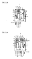
- FIGs. 1A to 1C are diagrams illustrating the schematic configuration of an electromagnetic relay 1 according to a present embodiment.
- FIG. 1A illustrate a left side face of the electromagnetic relay 1.
- FIG. 1B illustrate a front face of the electromagnetic relay 1.
- FIG. 1C illustrate a right side face of the electromagnetic relay 1.
- the electromagnetic relay 1 includes a fixing mold 2 corresponding to a frame, a spool 5, a coil 6, an iron core 7, movable springs 10 and 20, fixed contact plates 9 and 21, a return spring 11, a coil terminal 12, an armature 13, a hinge spring 14, a movable terminal 17 and a card 22.
- the movable springs 10 and 20 are plate springs, and the fixed contact plates 9 and 21 are metal such as brass.
- FIG. 2 illustrates the schematic configuration of the fixing mold 2.
- the fixing mold 2 is made of a resin or the like, and includes four projecting units 4 that can attach either the fixed contact plate 9 or 21.
- An insertion slot 4a for inserting the fixed contact plate 9 or 21 is formed on an upper part of each of the projecting units 4.
- a groove 4b is formed on the upper part of each of the projecting units 4 so that a part of the fixed contact plate 9 or 21 contacts the upper part of each of the projecting units 4.
- the fixing mold 2 includes a regulating unit 15 that extends upward and regulates the movement of the armature 13.
- a groove 2b for placing the spool 5, the coil 6 and the iron core 7 which constitute an electromagnet is formed on the fixing mold 2.
- a hole, a slot and a rib for mounting respective parts are properly formed on the fixing mold 2.
- the fixed contact plate 9 is inserted into one of the projecting units 4 (i.e., the projecting unit 4 of the left side). Then, a pair of movable springs 10 (i.e., two movable springs 10) are provided on both sides of the fixed contact plate 9 so as to be opposite to the fixed contact plate 9.
- the fixed contact plate 21 is inserted into one of the projecting units 4 (i.e., the projecting unit 4 of the right side). Then, a pair of movable springs 20 (i.e., two movable springs 20) are provided on both sides of the fixed contact plate 21 so as to be opposite to the fixed contact plate 21. As illustrated in FIGs.
- FIG. 3A illustrates the schematic configuration of the movable spring 10
- FIG. 3B illustrates the schematic configuration of the movable spring 20
- FIG. 3C is a side view of the pair of movable springs 10 and 20.
- FIG. 3D illustrates the schematic configuration of the movable terminal 17.
- FIGs. 4A and 4B illustrate the fixed contact plates 9 and 21, respectively.
- a cut 10c is formed near the upper end of the movable spring 10, and two spring elements 10d are formed.
- Contacts 10a (hereinafter, each contact thereof is also referred to as "a twin contact") constituting twin contacts are provided on the respective spring elements 10d.
- the twin contacts 10a are contacts for handling a low load (e.g. a load of a control system which processes an electric current of 10mA). Even if the twin contact 10a provided on one of the spring elements 10d and a fixed contact mentioned later becomes contact failure, contact with the fixed contact can be maintained by the twin contact 10a provided on the other one of the spring elements 10d.
- the twin contacts 10a can secure reliability of the contact. Moreover, a stopper 10b that contacts the fixing mold 2 and regulates a limit location of the insertion of the movable spring 10 is formed near a lower end of the movable spring 10.
- a single contact 20a is provided near the upper end of the movable spring 20.
- the single contact 20a is a contact for handling a high load (e.g. a load of a power supply system which processes an electric current of 5A). Since the single contact 20a is larger than the movable spring 10, the single contact 20a prevents the contacts from being welded and being worn away at the time of the high load, and is excellent in the durability. Therefore, the single contact 20a can secure reliability of the contact in the case of the high load.
- a stopper 20b that contacts the fixing mold 2 and regulates a limit position of the insertion of the movable spring 20 is formed near a lower end of the movable spring 20.
- the movable springs 10 and 20 are bent at positions (i.e. positions illustrated by a dotted line) located slightly above the stoppers 10b and 20b so as to come close to the fixed contact plates 9 and 21, respectively.
- the movable springs 10 and 20 are inserted from above the projecting units 4, but the movable terminal 17 of FIG. 3D is press-fitted from the bottom face of the fixing mold 2. At this time, each of the lower ends of the movable springs 10 and 20 is put between peripheral parts of a cut 17a of the movable terminal 17, and the movable springs 10 and 20 are electrically connected to the movable terminal 17.
- the fixed contact plate 9 includes two twin contacts 9a that contact the twin contacts 10a of the movable spring 10 of FIG. 3A .
- the twin contacts 9a are formed on each of front and rear faces of the fixed contact plate 9. Therefore, the pair of movable springs 10 and the fixed contact plate 9 form two switches of a normally-on switch and a normally-off switch.
- the normally-on switch means a switch that is in an on-state by contacting one contact with another contact when no coil voltage is applied.
- the normally-off switch means a switch that is in an off-state by separating one contact from another contact when no coil voltage is applied.
- the two switches of the normally-on switch and the normally-off switch can be provided for one projecting unit 4.
- only the pair of movable springs 10 and the fixed contact plate 9 constituting the normally-on switch, or only the pair of movable springs 10 and the fixed contact plate 9 constituting the normally-off switch may be provided for one projecting unit 4 according to a using way of the electromagnetic relay.
- the fixed contact plate 21 of FIG. 4B includes a single contact 21 a that contacts a single contact 20a of the movable spring 20 of FIG. 3B .
- the single contact 21 a are formed on each of front and rear faces of the fixed contact plate 21. Therefore, the pair of movable springs 20 and the fixed contact plate 21 form two switches of a normally-on switch and a normally-off switch. Only the pair of movable springs 20 and the fixed contact plate 21 constituting the normally-on switch, or only the pair of movable springs 20 and the fixed contact plate 21 constituting the normally-off switch may be provided for one projecting unit 4.
- the fixed contact plate 9 Since the fixed contact plate 9 is formed integrally to a fixed terminal 9b from a position where the twin contact 9a is provided, the fixed terminal 9b is exposed from the bottom of the fixing mold 2 by inserting the fixed contact plate 9 from the projecting unit 4, as illustrated in FIG. 1A . In this case, a jaw part 9c of the fixed contact plate 9 contacts the groove 4b of the projecting unit 4.
- the fixed contact plate 21 is formed integrally to a fixed terminal 21b from a position where the single contact 21 a is provided, the fixed terminal 21b is exposed from the bottom of the fixing mold 2 by inserting the fixed contact plate 21 from the projecting unit 4, as illustrated in FIG. 1C . In this case, a jaw part 21 c of the fixed contact plate 21 contacts the groove 4b of the projecting unit 4.
- FIG. 5A is a diagram illustrating the schematic configuration of the iron core 7.
- FIG. 5B is a diagram illustrating the schematic configuration of the coil terminal 12.
- FIG. 5C is a diagram illustrating the schematic configuration of the return spring 11.
- FIG. 6A is a sectional view of the electromagnetic relay 1 taken along a line B-B in FIG. 1B .
- FIG. 6B is a diagram of the electromagnetic relay 1 as seen from above. In FIG. 6B , two pairs of the movable springs 10 and two pairs of the movable springs 20 are provided.
- the iron core 7 is almost a U-shape, and one end of the iron core 7 (i.e., an end portion of an upper side of the iron core 7) is inserted into a central portion of the spool 5.
- a screw unit 8 extending vertically downward is provided on the iron core 7.
- the screw unit 8 is exposed to the outside via a through-hole 2a provided on the center of the fixing mold 2.
- the screw unit 8 exposed to the outside is fixed to the fixing mold 2 by a screw 19. That is, the iron core 7 is fixed to the fixing mold 2.
- the coil terminal 12 illustrated in FIG. 5B includes a head portion 12a, a terminal portion 12b and a stopper 12c.
- the coil terminal 12 is inserted into a through-hole, not shown, of the fixing mold 2 from above the projecting unit 4. At this time, the terminal portion 12b of the coil terminal 12 is exposed from the fixing mold 2, as illustrated in FIGs. 1A and 1C .
- the stopper 12c that regulates a limit position of the insertion of the coil terminal 12 is formed on the coil terminal 12.
- the coil 6 is wound on the head portion 12a, and is fixed thereto by a solder 16. Thereby, the coil terminal 12 is electrically connected to the coil 6.
- the return spring 11 illustrated in FIG. 5C has almost a U-shape so as to cover the iron core 7.
- Two through-holes 11a in which a part of card 22 is fitted are formed on an upper part of the return spring 11.
- the return spring 11 is coupled with the card 22, and pushes the card 22 toward the armature 13.
- the return spring 11 includes fixed portions 11b for fixing the return spring 11 to the fixing mold 2.
- leg portions 11 c are bent at a position of a dotted line to push the card 22 toward the armature 13.
- the armature 13 is provided between the iron core 7 and the regulating unit 15, and the hinge spring 14 is provided between the armature 13 and the regulating unit 15. As illustrated in FIGs. 6A and 6B , an upper end of the armature 13 is fixed to the card 22.
- the card 22 is formed with almost a rectangular flat plate, and an opening 22c which exposes the coil 6 is formed on the center of the card 22.
- a concave portion 22b for fixing the armature 13 is formed on a rear face side (i.e., a left side of FIG. 6B ) of the card 22.
- two pairs of projections 22a are projected from each of the right and the left side faces of the flat plate.
- a space is formed between each pair of projections 22a.
- the movable springs 10 contact the respective outsides from the spaces of the two pairs of projections 22a on the right side face (i.e., an upper side of FIG. 6B ).
- the movable springs 20 contact the respective outsides from the spaces of the two pairs of projections 22a on the left side face (i.e., a lower side of FIG. 6B ).
- FIG. 7A is a diagram illustrating a non-operation state of the electromagnetic relay 1.
- FIG. 7B is a diagram illustrating an operation state of the electromagnetic relay 1.
- the fixed contact plate 21 is provided on each of two projecting units 4.
- the movable springs 10 and the fixed contact plates 9 are provided on the projecting units 4, the operation like FIGs. 7A and 7B is performed.
- the iron core 7 does not attract the armature 13 by an electromagnetic force, and the return spring 11 pushes the card 22 in a left direction of FIG. 7A .
- the armature 13 is pushed in the left direction of FIG. 7A by the card 22, and contacts the regulating unit 15.
- the respective movable springs 20 in which the upper ends contacts the card 22 are moved in the left direction of FIG. 7A .
- the contact 20a on the movable spring 20, in the pair of movable springs 20, located on a right side of the fixed contact plate 21 contacts the contact 21 a of the fixed contact plate 21, and the contact 20a on the movable spring 20 located on a left side of the fixed contact plate 21 does not contact the contact 21 a.
- the contact 20a on the movable spring 20, in the pair of movable springs 20, located on the left side of the fixed contact plate 21 contacts the contact 21 a of the fixed contact plate 21, and a contact state between the contact 21 a and the contact 20a on the movable spring 20 located on the right side of the fixed contact plate 21 is released.
- the electromagnetic relay 1 becomes the non-operation state of FIG. 7A .
- the electromagnetic relay 1 becomes the operation state of FIG. 7B .
- on/off of the voltage to be applied to the coil 6 is switched, the operation state of FIG. 7B and the non-operation state of FIG. 7A are alternately switched.
- FIG. 8A is a diagram schematically illustrating the circuit configuration of the electromagnetic relay 1.
- FIG. 8B is a time chart illustrating the operation of the electromagnetic relay 1.
- the electromagnetic relay 1 includes four switch sets 31 to 34, and coil terminals D and E.
- the number of switch sets included in the electromagnetic relay 1 is not limited to four.
- Each of the coil terminals D and E corresponds to the above-mentioned coil terminals 12.
- Each of the switch sets 31 to 34 has three contacts composed of two movable contacts and a single fixed contact, and forms the two switches of the normally-on switch and the normally-off switch.
- the switch set 31 includes two movable contacts 31 A and 31B, and a single fixed contact 31c, constitutes the normally-on switch by the contacts 31 C and 31 B, and constitutes the normally-off switch by the contacts 31 C and 31 A.
- Each of the switch sets 31 to 34 corresponds to any one of a set of the twin contacts 10a on the pair of movable springs 10 and the twin contacts 9a on the fixed contact plate 9 disposed between the movable springs 10, or a set of the single contacts 20a on the pair of movable springs 20 and the single contacts 21 a on the fixed contact plate 21 disposed between the movable springs 20.
- the contact 31 c corresponds to the twin contacts 9a on the fixed contact plate 9
- each of the contacts 31A and 31B corresponds to the twin contacts 10a on the pair of movable springs 10.
- the switch set 32 corresponds to the set of the single contacts 20a on the pair of movable springs 20 and the single contacts 21a on the fixed contact plate 21 disposed between the movable springs 20, for example, the contact 32C corresponds to the single contacts 21 a on the fixed contact plate 21, and each of the contacts 31 A and 31B corresponds to the single contacts 20a on the pair of movable springs 20.
- the card moves by a biasing force of the return spring, and after a constant time lag, the contacts to be connected to the contacts 31C, 32C, 33C and 34C are simultaneously switched from the contacts 31A, 32A, 33A and 34A to the contacts 31B, 32B, 33B and 34B, respectively.
- the plurality of switches can be switched simultaneously, and it is possible to handle a plurality of loads at the same time by forming contact configuration of each switch so as to be suited for a desired load.
- the switch sets 31 to 34 include the pair of movable springs 10 and the fixed contact plate 9 disposed between the movable springs 10, and the pair of movable springs 20 and the fixed contact plate 21 disposed between the movable springs 20, it is possible to handle the high load and the low load at the same time.
- the electromagnetic relay 1 of FIGs. 1A and 1C has a twin contact set that includes the twin contacts 10a on the pair of movable springs 10 and the twin contacts 9a on the fixed contact plate 9 disposed between the movable springs 10, and a single contact set that includes the single contacts 20a on the pair of movable springs 20 and the single contacts 21 a on the fixed contact plate 21 disposed between the movable springs 20.
- each of the number of twin contact sets and the number of single contact sets is not limited to one.
- the electromagnetic relay 1 may include two twin contact sets and two single contact sets, as illustrated in FIGs. 9A and 9B . Moreover, the electromagnetic relay 1 may include one twin contact set and three single contact sets, as illustrated in FIGs. 10A and 10B . On the contrary, the electromagnetic relay 1 may include three twin contact sets and one single contact set. In addition, the electromagnetic relay 1 may include one twin contact set and two single contact sets, as illustrated in FIGs. 11A and 11B . On the contrary, the electromagnetic relay 1 may include two twin contact sets and one single contact set. In this case, the fixed contact plate 9 or 21 is not provided on one of the projecting units 4.
- the number of the projecting units 4 included in the fixing mold 2 is not limited to four.
- the fixing mold 2 needs to include at least two projecting units 4.
- the plurality of projecting units 4 are disposed so as to be opposite to the right and the left side faces of the electromagnet, the plurality of projecting units 4 may be disposed so as to be opposite to only one of the right and the left side faces of the electromagnet.
- the electromagnetic relay 1 includes: the electromagnet composed of the spool 5, the coil 6 and the iron core 7; the twin contact set that includes the twin contacts 10a provided on the movable spring 10, and the twin contacts 9a that are provided on the fixed contact plate 9 and disposed opposite to the twin contacts 10a; the single contact set that includes the single contact 20a provided on the movable spring 20, and the single contact 21 a that is provided on the fixed contact plate 21 and disposed opposite to the single contact 20a; and the card 22 that moves in response to the excitation or non-excitation of the electromagnet, and moves the movable springs 10 and 20 simultaneously with the movement of the card 22. Therefore, the electromagnetic relay 1 can simultaneously handle the high load (e.g. the load of the power supply system which processes the electric current of 5A) and the low load (e.g. the load of the control system which processes the electric current of 10mA), and can secure reliability of the contact.
- the high load e.g. the load of the power supply system which processes the electric current of 5A
- the electromagnetic relay 1 includes: the armature 13 that adjoins one end of the electromagnet in a longitudinal direction, and is attracted by the electromagnetic force of the electromagnet; the card 22 that is fixed to the armature 13 and includes a plurality of pairs of projections 22a extending toward the right and the left side faces of the electromagnet; and the return spring 11 that is opposite to another end of the electromagnet in the longitudinal direction, is coupled with the card 22, and biases the card 22 toward the armature 13; wherein the upper ends of the pair of movable springs 10 and the pair of movable springs 20 contact the plurality of pairs of projections 22a, and follow the movement of the card 22. Therefore, the twin contacts 10a on the pair of movable springs 10 and the single contacts 20a on the pair of movable springs 20 can be simultaneously turned on or off in accordance with the movement of the card 22.
Landscapes
- Physics & Mathematics (AREA)
- Electromagnetism (AREA)
- Electromagnets (AREA)
- Relay Circuits (AREA)
Applications Claiming Priority (1)
| Application Number | Priority Date | Filing Date | Title |
|---|---|---|---|
| JP2014029784A JP6325278B2 (ja) | 2014-02-19 | 2014-02-19 | 電磁継電器 |
Publications (3)
| Publication Number | Publication Date |
|---|---|
| EP2911175A1 true EP2911175A1 (de) | 2015-08-26 |
| EP2911175B1 EP2911175B1 (de) | 2018-01-10 |
| EP2911175B8 EP2911175B8 (de) | 2018-02-21 |
Family
ID=52396597
Family Applications (1)
| Application Number | Title | Priority Date | Filing Date |
|---|---|---|---|
| EP15152910.4A Not-in-force EP2911175B8 (de) | 2014-02-19 | 2015-01-28 | Elektromagnetisches Relais |
Country Status (4)
| Country | Link |
|---|---|
| US (1) | US9793078B2 (de) |
| EP (1) | EP2911175B8 (de) |
| JP (1) | JP6325278B2 (de) |
| CN (1) | CN104851750B (de) |
Families Citing this family (4)
| Publication number | Priority date | Publication date | Assignee | Title |
|---|---|---|---|---|
| USD787450S1 (en) * | 2014-12-04 | 2017-05-23 | Omron Corporation | Electric relay |
| JP2017201593A (ja) * | 2016-05-02 | 2017-11-09 | 富士通コンポーネント株式会社 | 電磁継電器 |
| JP7543743B2 (ja) | 2020-07-10 | 2024-09-03 | オムロン株式会社 | 電磁継電器 |
| CN111956058B (zh) * | 2020-08-27 | 2021-06-01 | 乐清市通达有线电厂 | 压力锅锅盖保护开关 |
Citations (7)
| Publication number | Priority date | Publication date | Assignee | Title |
|---|---|---|---|---|
| US3824511A (en) * | 1972-04-17 | 1974-07-16 | Siemens Ag | Electromagnetic relay |
| US4027131A (en) * | 1974-09-13 | 1977-05-31 | Siemens Aktiengesellschaft | Spring contact assembly |
| DE3625706A1 (de) * | 1986-07-30 | 1988-02-11 | Siemens Ag | Elektromagnetisches relais |
| JPH05242753A (ja) | 1992-02-28 | 1993-09-21 | Matsushita Electric Works Ltd | 接点開閉装置及び電磁リレー |
| JP2000149748A (ja) | 1998-11-09 | 2000-05-30 | Omron Corp | 電磁継電器 |
| FR2811470A1 (fr) * | 2000-07-05 | 2002-01-11 | Chauvin Arnoux | Relais electromagnetique comportant un bloc pour le logement des organes de contact et d'un coulisseau de commande des contacts mobiles |
| US20130222084A1 (en) * | 2010-11-08 | 2013-08-29 | Panasonic Corporation | Electromagnetic relay |
Family Cites Families (14)
| Publication number | Priority date | Publication date | Assignee | Title |
|---|---|---|---|---|
| NL40118C (de) * | 1934-02-23 | |||
| JPS4733473Y1 (de) * | 1969-02-05 | 1972-10-09 | ||
| JPS6092432U (ja) * | 1983-11-30 | 1985-06-24 | 松下電工株式会社 | 電磁継電器 |
| JPH09231896A (ja) | 1996-02-20 | 1997-09-05 | Nec Corp | シーソー式電磁継電器 |
| JPH11339623A (ja) | 1998-05-26 | 1999-12-10 | Matsushita Electric Works Ltd | 電磁継電器 |
| DE19847831C2 (de) * | 1998-10-16 | 2002-11-21 | Tyco Electronics Austria Gmbh | Sicherheitsrelais |
| ES2445990T3 (es) * | 2000-01-28 | 2014-03-06 | Elesta Relays Gmbh | Relé de seguridad, su uso y dispositivo de conexión con tal relé de seguridad |
| JP3934376B2 (ja) | 2001-10-01 | 2007-06-20 | タイコ エレクトロニクス イーシー株式会社 | 電磁継電器 |
| EP1308976A1 (de) * | 2001-11-06 | 2003-05-07 | ELESTA relays GmbH | Relais |
| JP4424260B2 (ja) | 2005-06-07 | 2010-03-03 | オムロン株式会社 | 電磁リレー |
| CH698492B1 (de) * | 2006-03-20 | 2009-08-31 | Elesta Relays Gmbh | Relais. |
| JP2009231032A (ja) * | 2008-03-24 | 2009-10-08 | Kyosan Electric Mfg Co Ltd | 電磁継電器 |
| JP5521852B2 (ja) * | 2010-03-30 | 2014-06-18 | アンデン株式会社 | 電磁継電器 |
| JP5838920B2 (ja) * | 2011-07-18 | 2016-01-06 | アンデン株式会社 | 継電器 |
-
2014
- 2014-02-19 JP JP2014029784A patent/JP6325278B2/ja active Active
-
2015
- 2015-01-28 EP EP15152910.4A patent/EP2911175B8/de not_active Not-in-force
- 2015-01-30 US US14/609,506 patent/US9793078B2/en active Active
- 2015-02-16 CN CN201510083325.5A patent/CN104851750B/zh active Active
Patent Citations (7)
| Publication number | Priority date | Publication date | Assignee | Title |
|---|---|---|---|---|
| US3824511A (en) * | 1972-04-17 | 1974-07-16 | Siemens Ag | Electromagnetic relay |
| US4027131A (en) * | 1974-09-13 | 1977-05-31 | Siemens Aktiengesellschaft | Spring contact assembly |
| DE3625706A1 (de) * | 1986-07-30 | 1988-02-11 | Siemens Ag | Elektromagnetisches relais |
| JPH05242753A (ja) | 1992-02-28 | 1993-09-21 | Matsushita Electric Works Ltd | 接点開閉装置及び電磁リレー |
| JP2000149748A (ja) | 1998-11-09 | 2000-05-30 | Omron Corp | 電磁継電器 |
| FR2811470A1 (fr) * | 2000-07-05 | 2002-01-11 | Chauvin Arnoux | Relais electromagnetique comportant un bloc pour le logement des organes de contact et d'un coulisseau de commande des contacts mobiles |
| US20130222084A1 (en) * | 2010-11-08 | 2013-08-29 | Panasonic Corporation | Electromagnetic relay |
Also Published As
| Publication number | Publication date |
|---|---|
| JP2015153738A (ja) | 2015-08-24 |
| CN104851750A (zh) | 2015-08-19 |
| JP6325278B2 (ja) | 2018-05-16 |
| EP2911175B1 (de) | 2018-01-10 |
| CN104851750B (zh) | 2018-05-29 |
| US20150235792A1 (en) | 2015-08-20 |
| US9793078B2 (en) | 2017-10-17 |
| EP2911175B8 (de) | 2018-02-21 |
Similar Documents
| Publication | Publication Date | Title |
|---|---|---|
| CN106057586B (zh) | 触点装置以及电磁继电器 | |
| USRE49236E1 (en) | Contact device and electromagnetic relay | |
| US9412545B2 (en) | Electromagnetic relay | |
| US10163588B2 (en) | Electromagnetic relay including yoke-retaining bottom plate | |
| CN102222588B (zh) | 电磁继电器 | |
| KR102159887B1 (ko) | 전자기 릴레이 | |
| EP2911175B1 (de) | Elektromagnetisches Relais | |
| KR20130138361A (ko) | 전자 릴레이 | |
| US8050008B2 (en) | Relay device | |
| US11133140B2 (en) | Contact device and electromagnetic relay | |
| US20200279708A1 (en) | Contact device and electromagnetic relay equipped with contact device | |
| JP2018129300A (ja) | リレー | |
| US20080001689A1 (en) | Electromagnetic relay | |
| JP2009199893A (ja) | 電磁継電器 | |
| JP4645663B2 (ja) | リレー | |
| KR101503316B1 (ko) | 전자접촉기 | |
| US10468218B2 (en) | Relay with SMA wire driven mechanism | |
| JP4953828B2 (ja) | 電磁石装置及び電磁継電器 | |
| JP4289301B2 (ja) | 電磁継電器 | |
| CN107251184A (zh) | 线圈端子及具备线圈端子的电磁继电器 | |
| EP2482295A1 (de) | Relais mit mehreren Kontakten | |
| KR102197518B1 (ko) | 전자 접촉기 | |
| US20220102102A1 (en) | Relay | |
| CN117690757A (zh) | 电磁体装置和电磁继电器 | |
| JP2018037164A (ja) | 外部端子及び電磁リレー |
Legal Events
| Date | Code | Title | Description |
|---|---|---|---|
| PUAI | Public reference made under article 153(3) epc to a published international application that has entered the european phase |
Free format text: ORIGINAL CODE: 0009012 |
|
| AK | Designated contracting states |
Kind code of ref document: A1 Designated state(s): AL AT BE BG CH CY CZ DE DK EE ES FI FR GB GR HR HU IE IS IT LI LT LU LV MC MK MT NL NO PL PT RO RS SE SI SK SM TR |
|
| AX | Request for extension of the european patent |
Extension state: BA ME |
|
| 17P | Request for examination filed |
Effective date: 20160219 |
|
| RBV | Designated contracting states (corrected) |
Designated state(s): AL AT BE BG CH CY CZ DE DK EE ES FI FR GB GR HR HU IE IS IT LI LT LU LV MC MK MT NL NO PL PT RO RS SE SI SK SM TR |
|
| GRAP | Despatch of communication of intention to grant a patent |
Free format text: ORIGINAL CODE: EPIDOSNIGR1 |
|
| STAA | Information on the status of an ep patent application or granted ep patent |
Free format text: STATUS: GRANT OF PATENT IS INTENDED |
|
| RIC1 | Information provided on ipc code assigned before grant |
Ipc: H01H 50/64 20060101AFI20170717BHEP Ipc: H01H 50/56 20060101ALI20170717BHEP Ipc: H01H 50/04 20060101ALI20170717BHEP Ipc: H01H 1/26 20060101ALN20170717BHEP |
|
| RIC1 | Information provided on ipc code assigned before grant |
Ipc: H01H 1/26 20060101ALN20170724BHEP Ipc: H01H 50/56 20060101ALI20170724BHEP Ipc: H01H 50/04 20060101ALI20170724BHEP Ipc: H01H 50/64 20060101AFI20170724BHEP |
|
| INTG | Intention to grant announced |
Effective date: 20170808 |
|
| RIN1 | Information on inventor provided before grant (corrected) |
Inventor name: KURATA, YOSHINORI Inventor name: TAKAHASHI, KATSUYUKI Inventor name: KITAJIMA, DAISHI |
|
| GRAS | Grant fee paid |
Free format text: ORIGINAL CODE: EPIDOSNIGR3 |
|
| GRAA | (expected) grant |
Free format text: ORIGINAL CODE: 0009210 |
|
| STAA | Information on the status of an ep patent application or granted ep patent |
Free format text: STATUS: THE PATENT HAS BEEN GRANTED |
|
| AK | Designated contracting states |
Kind code of ref document: B1 Designated state(s): AL AT BE BG CH CY CZ DE DK EE ES FI FR GB GR HR HU IE IS IT LI LT LU LV MC MK MT NL NO PL PT RO RS SE SI SK SM TR |
|
| REG | Reference to a national code |
Ref country code: AT Ref legal event code: REF Ref document number: 963269 Country of ref document: AT Kind code of ref document: T Effective date: 20180115 Ref country code: CH Ref legal event code: EP |
|
| RAP2 | Party data changed (patent owner data changed or rights of a patent transferred) |
Owner name: FUJITSU COMPONENT LIMITED |
|
| REG | Reference to a national code |
Ref country code: IE Ref legal event code: FG4D |
|
| RIN2 | Information on inventor provided after grant (corrected) |
Inventor name: TAKAHASHI, KATSUYUKI Inventor name: KURATA, YOSHINORI Inventor name: KITAJIMA, DAISHI |
|
| REG | Reference to a national code |
Ref country code: DE Ref legal event code: R096 Ref document number: 602015007265 Country of ref document: DE |
|
| REG | Reference to a national code |
Ref country code: FR Ref legal event code: PLFP Year of fee payment: 4 |
|
| REG | Reference to a national code |
Ref country code: NL Ref legal event code: MP Effective date: 20180110 |
|
| REG | Reference to a national code |
Ref country code: AT Ref legal event code: MK05 Ref document number: 963269 Country of ref document: AT Kind code of ref document: T Effective date: 20180110 |
|
| PG25 | Lapsed in a contracting state [announced via postgrant information from national office to epo] |
Ref country code: NL Free format text: LAPSE BECAUSE OF FAILURE TO SUBMIT A TRANSLATION OF THE DESCRIPTION OR TO PAY THE FEE WITHIN THE PRESCRIBED TIME-LIMIT Effective date: 20180110 |
|
| PG25 | Lapsed in a contracting state [announced via postgrant information from national office to epo] |
Ref country code: HR Free format text: LAPSE BECAUSE OF FAILURE TO SUBMIT A TRANSLATION OF THE DESCRIPTION OR TO PAY THE FEE WITHIN THE PRESCRIBED TIME-LIMIT Effective date: 20180110 Ref country code: FI Free format text: LAPSE BECAUSE OF FAILURE TO SUBMIT A TRANSLATION OF THE DESCRIPTION OR TO PAY THE FEE WITHIN THE PRESCRIBED TIME-LIMIT Effective date: 20180110 Ref country code: NO Free format text: LAPSE BECAUSE OF FAILURE TO SUBMIT A TRANSLATION OF THE DESCRIPTION OR TO PAY THE FEE WITHIN THE PRESCRIBED TIME-LIMIT Effective date: 20180410 Ref country code: CY Free format text: LAPSE BECAUSE OF FAILURE TO SUBMIT A TRANSLATION OF THE DESCRIPTION OR TO PAY THE FEE WITHIN THE PRESCRIBED TIME-LIMIT Effective date: 20180110 Ref country code: LT Free format text: LAPSE BECAUSE OF FAILURE TO SUBMIT A TRANSLATION OF THE DESCRIPTION OR TO PAY THE FEE WITHIN THE PRESCRIBED TIME-LIMIT Effective date: 20180110 Ref country code: ES Free format text: LAPSE BECAUSE OF FAILURE TO SUBMIT A TRANSLATION OF THE DESCRIPTION OR TO PAY THE FEE WITHIN THE PRESCRIBED TIME-LIMIT Effective date: 20180110 |
|
| PG25 | Lapsed in a contracting state [announced via postgrant information from national office to epo] |
Ref country code: IS Free format text: LAPSE BECAUSE OF FAILURE TO SUBMIT A TRANSLATION OF THE DESCRIPTION OR TO PAY THE FEE WITHIN THE PRESCRIBED TIME-LIMIT Effective date: 20180510 Ref country code: SE Free format text: LAPSE BECAUSE OF FAILURE TO SUBMIT A TRANSLATION OF THE DESCRIPTION OR TO PAY THE FEE WITHIN THE PRESCRIBED TIME-LIMIT Effective date: 20180110 Ref country code: LV Free format text: LAPSE BECAUSE OF FAILURE TO SUBMIT A TRANSLATION OF THE DESCRIPTION OR TO PAY THE FEE WITHIN THE PRESCRIBED TIME-LIMIT Effective date: 20180110 Ref country code: RS Free format text: LAPSE BECAUSE OF FAILURE TO SUBMIT A TRANSLATION OF THE DESCRIPTION OR TO PAY THE FEE WITHIN THE PRESCRIBED TIME-LIMIT Effective date: 20180110 Ref country code: PL Free format text: LAPSE BECAUSE OF FAILURE TO SUBMIT A TRANSLATION OF THE DESCRIPTION OR TO PAY THE FEE WITHIN THE PRESCRIBED TIME-LIMIT Effective date: 20180110 Ref country code: BG Free format text: LAPSE BECAUSE OF FAILURE TO SUBMIT A TRANSLATION OF THE DESCRIPTION OR TO PAY THE FEE WITHIN THE PRESCRIBED TIME-LIMIT Effective date: 20180410 Ref country code: GR Free format text: LAPSE BECAUSE OF FAILURE TO SUBMIT A TRANSLATION OF THE DESCRIPTION OR TO PAY THE FEE WITHIN THE PRESCRIBED TIME-LIMIT Effective date: 20180411 Ref country code: AT Free format text: LAPSE BECAUSE OF FAILURE TO SUBMIT A TRANSLATION OF THE DESCRIPTION OR TO PAY THE FEE WITHIN THE PRESCRIBED TIME-LIMIT Effective date: 20180110 |
|
| REG | Reference to a national code |
Ref country code: CH Ref legal event code: PL |
|
| REG | Reference to a national code |
Ref country code: DE Ref legal event code: R097 Ref document number: 602015007265 Country of ref document: DE |
|
| PG25 | Lapsed in a contracting state [announced via postgrant information from national office to epo] |
Ref country code: LU Free format text: LAPSE BECAUSE OF NON-PAYMENT OF DUE FEES Effective date: 20180128 Ref country code: IT Free format text: LAPSE BECAUSE OF FAILURE TO SUBMIT A TRANSLATION OF THE DESCRIPTION OR TO PAY THE FEE WITHIN THE PRESCRIBED TIME-LIMIT Effective date: 20180110 Ref country code: EE Free format text: LAPSE BECAUSE OF FAILURE TO SUBMIT A TRANSLATION OF THE DESCRIPTION OR TO PAY THE FEE WITHIN THE PRESCRIBED TIME-LIMIT Effective date: 20180110 Ref country code: AL Free format text: LAPSE BECAUSE OF FAILURE TO SUBMIT A TRANSLATION OF THE DESCRIPTION OR TO PAY THE FEE WITHIN THE PRESCRIBED TIME-LIMIT Effective date: 20180110 Ref country code: MC Free format text: LAPSE BECAUSE OF FAILURE TO SUBMIT A TRANSLATION OF THE DESCRIPTION OR TO PAY THE FEE WITHIN THE PRESCRIBED TIME-LIMIT Effective date: 20180110 Ref country code: RO Free format text: LAPSE BECAUSE OF FAILURE TO SUBMIT A TRANSLATION OF THE DESCRIPTION OR TO PAY THE FEE WITHIN THE PRESCRIBED TIME-LIMIT Effective date: 20180110 |
|
| REG | Reference to a national code |
Ref country code: IE Ref legal event code: MM4A |
|
| REG | Reference to a national code |
Ref country code: BE Ref legal event code: MM Effective date: 20180131 |
|
| PLBE | No opposition filed within time limit |
Free format text: ORIGINAL CODE: 0009261 |
|
| STAA | Information on the status of an ep patent application or granted ep patent |
Free format text: STATUS: NO OPPOSITION FILED WITHIN TIME LIMIT |
|
| PG25 | Lapsed in a contracting state [announced via postgrant information from national office to epo] |
Ref country code: CZ Free format text: LAPSE BECAUSE OF FAILURE TO SUBMIT A TRANSLATION OF THE DESCRIPTION OR TO PAY THE FEE WITHIN THE PRESCRIBED TIME-LIMIT Effective date: 20180110 Ref country code: SK Free format text: LAPSE BECAUSE OF FAILURE TO SUBMIT A TRANSLATION OF THE DESCRIPTION OR TO PAY THE FEE WITHIN THE PRESCRIBED TIME-LIMIT Effective date: 20180110 Ref country code: BE Free format text: LAPSE BECAUSE OF NON-PAYMENT OF DUE FEES Effective date: 20180131 Ref country code: SM Free format text: LAPSE BECAUSE OF FAILURE TO SUBMIT A TRANSLATION OF THE DESCRIPTION OR TO PAY THE FEE WITHIN THE PRESCRIBED TIME-LIMIT Effective date: 20180110 Ref country code: CH Free format text: LAPSE BECAUSE OF NON-PAYMENT OF DUE FEES Effective date: 20180131 Ref country code: DK Free format text: LAPSE BECAUSE OF FAILURE TO SUBMIT A TRANSLATION OF THE DESCRIPTION OR TO PAY THE FEE WITHIN THE PRESCRIBED TIME-LIMIT Effective date: 20180110 Ref country code: LI Free format text: LAPSE BECAUSE OF NON-PAYMENT OF DUE FEES Effective date: 20180131 |
|
| 26N | No opposition filed |
Effective date: 20181011 |
|
| PG25 | Lapsed in a contracting state [announced via postgrant information from national office to epo] |
Ref country code: IE Free format text: LAPSE BECAUSE OF NON-PAYMENT OF DUE FEES Effective date: 20180128 |
|
| PG25 | Lapsed in a contracting state [announced via postgrant information from national office to epo] |
Ref country code: SI Free format text: LAPSE BECAUSE OF FAILURE TO SUBMIT A TRANSLATION OF THE DESCRIPTION OR TO PAY THE FEE WITHIN THE PRESCRIBED TIME-LIMIT Effective date: 20180110 |
|
| PG25 | Lapsed in a contracting state [announced via postgrant information from national office to epo] |
Ref country code: MT Free format text: LAPSE BECAUSE OF NON-PAYMENT OF DUE FEES Effective date: 20180128 |
|
| PGFP | Annual fee paid to national office [announced via postgrant information from national office to epo] |
Ref country code: FR Payment date: 20191216 Year of fee payment: 6 |
|
| PG25 | Lapsed in a contracting state [announced via postgrant information from national office to epo] |
Ref country code: TR Free format text: LAPSE BECAUSE OF FAILURE TO SUBMIT A TRANSLATION OF THE DESCRIPTION OR TO PAY THE FEE WITHIN THE PRESCRIBED TIME-LIMIT Effective date: 20180110 |
|
| PGFP | Annual fee paid to national office [announced via postgrant information from national office to epo] |
Ref country code: DE Payment date: 20200114 Year of fee payment: 6 Ref country code: GB Payment date: 20200115 Year of fee payment: 6 |
|
| PG25 | Lapsed in a contracting state [announced via postgrant information from national office to epo] |
Ref country code: PT Free format text: LAPSE BECAUSE OF FAILURE TO SUBMIT A TRANSLATION OF THE DESCRIPTION OR TO PAY THE FEE WITHIN THE PRESCRIBED TIME-LIMIT Effective date: 20180110 |
|
| PG25 | Lapsed in a contracting state [announced via postgrant information from national office to epo] |
Ref country code: HU Free format text: LAPSE BECAUSE OF FAILURE TO SUBMIT A TRANSLATION OF THE DESCRIPTION OR TO PAY THE FEE WITHIN THE PRESCRIBED TIME-LIMIT; INVALID AB INITIO Effective date: 20150128 Ref country code: MK Free format text: LAPSE BECAUSE OF NON-PAYMENT OF DUE FEES Effective date: 20180110 |
|
| REG | Reference to a national code |
Ref country code: DE Ref legal event code: R082 Ref document number: 602015007265 Country of ref document: DE Representative=s name: HL KEMPNER PATENTANWALT, RECHTSANWALT, SOLICIT, DE |
|
| REG | Reference to a national code |
Ref country code: DE Ref legal event code: R119 Ref document number: 602015007265 Country of ref document: DE |
|
| GBPC | Gb: european patent ceased through non-payment of renewal fee |
Effective date: 20210128 |
|
| PG25 | Lapsed in a contracting state [announced via postgrant information from national office to epo] |
Ref country code: FR Free format text: LAPSE BECAUSE OF NON-PAYMENT OF DUE FEES Effective date: 20210131 |
|
| PG25 | Lapsed in a contracting state [announced via postgrant information from national office to epo] |
Ref country code: DE Free format text: LAPSE BECAUSE OF NON-PAYMENT OF DUE FEES Effective date: 20210803 Ref country code: GB Free format text: LAPSE BECAUSE OF NON-PAYMENT OF DUE FEES Effective date: 20210128 |