EP2911210B1 - Générateur d'électricité à faible impact sur l'environnement pour un véhicule à essence - Google Patents
Générateur d'électricité à faible impact sur l'environnement pour un véhicule à essence Download PDFInfo
- Publication number
- EP2911210B1 EP2911210B1 EP15155810.3A EP15155810A EP2911210B1 EP 2911210 B1 EP2911210 B1 EP 2911210B1 EP 15155810 A EP15155810 A EP 15155810A EP 2911210 B1 EP2911210 B1 EP 2911210B1
- Authority
- EP
- European Patent Office
- Prior art keywords
- fuel
- vehicle
- electricity generator
- heat source
- heat
- Prior art date
- Legal status (The legal status is an assumption and is not a legal conclusion. Google has not performed a legal analysis and makes no representation as to the accuracy of the status listed.)
- Revoked
Links
Images


Classifications
-
- F—MECHANICAL ENGINEERING; LIGHTING; HEATING; WEAPONS; BLASTING
- F01—MACHINES OR ENGINES IN GENERAL; ENGINE PLANTS IN GENERAL; STEAM ENGINES
- F01N—GAS-FLOW SILENCERS OR EXHAUST APPARATUS FOR MACHINES OR ENGINES IN GENERAL; GAS-FLOW SILENCERS OR EXHAUST APPARATUS FOR INTERNAL-COMBUSTION ENGINES
- F01N5/00—Exhaust or silencing apparatus combined or associated with devices profiting by exhaust energy
- F01N5/02—Exhaust or silencing apparatus combined or associated with devices profiting by exhaust energy the devices using heat
- F01N5/025—Exhaust or silencing apparatus combined or associated with devices profiting by exhaust energy the devices using heat the device being thermoelectric generators
-
- H—ELECTRICITY
- H10—SEMICONDUCTOR DEVICES; ELECTRIC SOLID-STATE DEVICES NOT OTHERWISE PROVIDED FOR
- H10N—ELECTRIC SOLID-STATE DEVICES NOT OTHERWISE PROVIDED FOR
- H10N10/00—Thermoelectric devices comprising a junction of dissimilar materials, i.e. devices exhibiting Seebeck or Peltier effects
- H10N10/10—Thermoelectric devices comprising a junction of dissimilar materials, i.e. devices exhibiting Seebeck or Peltier effects operating with only the Peltier or Seebeck effects
- H10N10/13—Thermoelectric devices comprising a junction of dissimilar materials, i.e. devices exhibiting Seebeck or Peltier effects operating with only the Peltier or Seebeck effects characterised by the heat-exchanging means at the junction
-
- Y—GENERAL TAGGING OF NEW TECHNOLOGICAL DEVELOPMENTS; GENERAL TAGGING OF CROSS-SECTIONAL TECHNOLOGIES SPANNING OVER SEVERAL SECTIONS OF THE IPC; TECHNICAL SUBJECTS COVERED BY FORMER USPC CROSS-REFERENCE ART COLLECTIONS [XRACs] AND DIGESTS
- Y02—TECHNOLOGIES OR APPLICATIONS FOR MITIGATION OR ADAPTATION AGAINST CLIMATE CHANGE
- Y02T—CLIMATE CHANGE MITIGATION TECHNOLOGIES RELATED TO TRANSPORTATION
- Y02T10/00—Road transport of goods or passengers
- Y02T10/10—Internal combustion engine [ICE] based vehicles
- Y02T10/12—Improving ICE efficiencies
Definitions
- the present invention relates to an electricity generator for a vehicle run on fuel, as well as a vehicle provided with such electricity generator.
- US 2011/240080 discloses a method of controlling the temperature of a thermoelectric generator (TEG) in an exhaust system of an engine.
- the method includes determining the temperature of the heated side of the TEG, determining exhaust gas flow rate through the TEG, and determining the exhaust gas temperature through the TEG.
- a rate of change in temperature of the heated side of the TEG is predicted based on the determined temperature, the determined exhaust gas flow rate, and the determined exhaust gas temperature through the TEG.
- exhaust gas flow rate through the TEG is calculated that will result in a maximum temperature of the heated side of the TEG less than a predetermined critical temperature given the predicted rate of change in temperature of the heated side of the TEG.
- a corresponding apparatus is provided.
- US 2013/079981 discloses implementing an optimized waste heat recovery system, comprising calculating a temperature and a rate of change in temperature of a heat exchanger of a waste heat recovery system, and predicting a temperature and a rate of change in temperature of a material flowing through a channel of the waste heat recovery system.
- the optimized waste heat recovery system calculates a valve position and timing for the channel that is configurable for achieving a rate of material flow that is determined to produce and maintain a defined threshold temperature of the heat exchanger, and actuates the valve according to the calculated valve position and calculated timing.
- US2006/0066106 discloses an auxiliary electrical power generator for a vehicle.
- the generator has a vehicular fuel delivery system with a bulk fuel tank for storing liquid fuel and a fuel pump for providing pressurized liquid fuel to an internal combustion engine.
- a thermoelectric generator is close-coupled to a fuel combustor and converts the heat from fuel combustion into electrical power.
- a combustor fuel delivery system supplies the liquid fuel to the combustor for combustion.
- the aim of the present invention consists in providing an electricity generator for a vehicle run on fuel which compensates for the drawbacks and overcomes the limitations of the known art.
- an object of the present invention is to provide an electricity generator that has a minimal environmental and acoustic impact.
- Another object of the invention consists in providing an electricity generator that has no moving parts and therefore does not necessitate frequent maintenance.
- Another object of the invention consists in providing an electricity generator that can operate under any environmental conditions.
- Another object of the invention consists in providing an electricity generator that does not require a special and expensive type of fuel in order to operate.
- Another object of the invention consists in providing an electricity generator for which there are no difficulties in sourcing and storing the fuel to run it.
- Another object of the invention consists in providing an electricity generator that is capable of offering the widest guarantees of reliability and safety in use, and which is easy to provide and economically competitive when compared to the known art.
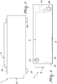
- the electricity generator for a vehicle which comprises at least one tank of a fuel, generally designated by the reference numeral 1, comprises at least one Seebeck-effect thermoelectric generator 3 coupled to a heat source 5 and to a heat sink 7, which are adapted to generate a thermal delta across the thermoelectric generator 3 in order to generate electricity, in the form of voltage and/or electric current.
- the electricity generator 1 further comprises a system 9 for the management and control of the thermal delta.
- the management and control system 9 is adapted to manage the heat generated by the heat source 5 and the heat dissipated by the heat sink 7, so as to control and vary the aforementioned thermal delta so that the thermoelectric generator 3 generates electricity with the maximum yield.
- the heat source 5 is supplied with the fuel present in the at least one tank of the vehicle.
- the tank of the vehicle containing the fuel for supplying the heat source 5 can be the tank that contains the fuel for supplying the vehicle, i.e. the fuel necessary in order to make the vehicle move forward.
- the tank of the vehicle containing the fuel for supplying the heat source 5 can be the tank that contains the fuel for supplying at least one of the user devices that are present on board the vehicle.
- the fuel for supplying the heat source 5 can be the gasoline or Diesel fuel contained in the tank of the vehicle.
- the vehicle it is also possible for the vehicle to be provided with both the above mentioned types of tank, and therefore the heat source 5 will be supplied by the fuel present in one of the two types of tank.
- the fuel for supplying the heat source 5 can be the fuel taken directly from the tank of the system required to ensure the operation of onboard user devices such as refrigerators, stoves and systems for heating the vehicle.
- such fuel can be gas, or even pellets.
- the Seebeck-effect thermoelectric generator 3 comprises a first terminal 30, which comprises a first flat element 31, and a second terminal 32, which comprises a second flat element 33. Between the first flat element 31 and the second flat element 33 there is a layer of semiconductor material 34.
- the heat source 5 faces the first flat element 31, in order to heat it, while the heat sink 7 faces, or is connected to, the second flat element 33 in order to cool it.
- thermoelectric generator 3 When the thermoelectric generator 3 is in operation, i.e. there is a thermal delta across it, electrical energy is generated at the ends of the terminals 30 and 32, in the form of voltage and/or current.
- the heat source 5 comprises a burner that is adapted to produce heat from the combustion of the fuel that is conveyed, by way of adapted supply means, from one of the tanks of the vehicle, directly to the heat source 5.
- the supply of fuel can be selected from the group constituted by gas, Diesel fuel, gasoline, propane gas, LPG, methane and pellets.
- the electricity generator 1 can comprise a remote control system 11, for example wireless, for interfacing with the management and control system 9.
- a remote control system 11 for example wireless
- the user by way of for example the display 110 of the remote control system 11, can set the operating parameters of the electricity generator 1 and display the information of interest.
- the remote control system 11 can also be a cellular telephone, a tablet computer or a computer.
- both the heat source 5 and the heat sink 7 each comprise a temperature sensor, indicated respectively with the reference numerals 50 and 70, which are connected to the management and control system 9.
- the management and control system 9 is capable of managing the operation of the heat source 5 and of the heat sink 7, ensuring the correct delivery of current by the thermoelectric generator 3.
- the heat source 5 can comprise a dedicated control system 51, which is connected to the management and control system 9.
- the heat sink 7 comprises a liquid cooling system, which is integrated in the thermoelectric generator 3 and comprises a pump 71.
- the heat sink 7 is adapted to maintain an operating temperature of the second flat element 33 of around 30°C.
- the heat sink 7 can advantageously comprise a cooling coil which is integrated in the terminal 32.
- the heat sink 7 comprises a heat absorption system, which comprises a forced ventilation system.
- the electricity generator 1 comprises a duct 23 for supplying the fuel, which brings the fuel from one of the tanks of the vehicle to the heat source 5.
- the electricity generator 1 comprises ducts 21, 22 for the passage of the air that circulates in the electricity generator 1.
- the electricity generator 1 comprises two thermoelectric generators 3, which are arranged inclined with respect to each other, so that both present the first flat element 31 to the heat source 5.
- the first flat elements 31 and the heat source 5 define an interspace 55, which has a triangular transverse cross-section.
- the heat generated by the heat source 5 is advantageously kept homogeneous, so as to equally heat the entire surface of both first flat elements of the two thermoelectric generators 3.
- the electricity generator 1 can comprise one or more thermoelectric generators 3, conveniently arranged and conveniently dimensioned.
- the electricity generator 1 can further comprise a plurality of modular thermoelectric generators 3 arranged and combined according to desired geometries.
- thermoelectric generator 3 Activation of the heat source 5 and of the heat sink 7 generates a thermal delta across the Seebeck-effect thermoelectric generator 3, and this determines, at the terminals 30 and 32 of the thermoelectric generator 3, the generation of electric power which can be used to charge the battery of a vehicle, or to run the electrical devices present on the vehicle.
- the heat source 5 is supplied by fuel originating directly from the vehicle, and more specifically from the tank containing the fuel for supplying the vehicle, and/or from other tanks containing fuels to supply the user devices on board the vehicle.
- the electricity generator for a vehicle run on fuel achieves the intended aim and objects in that it makes it possible to produce electric power from the fuel that is already present on the vehicle, even when the vehicle is stationary and the engine of the vehicle is switched off.
- Another advantage of the electricity generator, according to the invention consists in that it produces electric power, on vehicles, in absolute silence and with a reduced environmental impact.
- Another advantage of the electricity generator, according to the invention consists in that it is possible to vary the operating temperature so as to ensure the maximum yield.
- Another advantage of the electricity generator, according to the invention consists in that its operation can be controlled and managed remotely.
- Another advantage consists in that the electricity generator according to the invention has low running costs and simplicity of sourcing and storing of the fuel necessary to supply the heat source. In this manner the problems associated with the presence of hazardous fuels in the event of an accident are also eliminated.
Landscapes
- Engineering & Computer Science (AREA)
- Chemical & Material Sciences (AREA)
- Combustion & Propulsion (AREA)
- Mechanical Engineering (AREA)
- General Engineering & Computer Science (AREA)
- Cooling, Air Intake And Gas Exhaust, And Fuel Tank Arrangements In Propulsion Units (AREA)
Claims (6)
- Générateur d'électricité (1) pour véhicule comprenant au moins un réservoir adapté pour contenir un carburant, qui comprend au moins un générateur thermoélectrique à effet Seebeck (3) couplé à une source de chaleur (5) et à un dissipateur thermique (7) qui sont adaptés pour générer un delta thermique aux bornes dudit générateur thermoélectrique (3) afin de produire de l'électricité, et qui comprend un système (9) pour la commande et la gestion dudit delta thermique qui est adapté pour gérer la génération de chaleur et la dissipation de chaleur, ladite source de chaleur (5) comprenant un brûleur qui est alimenté avec ledit carburant dudit au moins un réservoir dudit véhicule, ladite source de chaleur (5) étant fonctionnelle indépendamment du fonctionnement du moteur du véhicule, caractérisé en ce que ledit dissipateur thermique (7) comprend un système de refroidissement liquide qui est intégré audit générateur thermoélectrique (3), ladite source de chaleur (5) et ledit dissipateur thermique (7) comprenant chacun un capteur de température (50, 70), qui est relié audit système de gestion et de commande (9), ledit système de gestion et de commande étant apte, en se basant sur les informations de température fournies par lesdits capteurs de température (50, 70), à gérer le fonctionnement de la source de chaleur (5) et du dissipateur thermique (7), ledit dissipateur thermique (7) comprenant en outre un système de ventilation forcée.
- Générateur d'électricité (1) selon la revendication 1, caractérisé en ce qu'il comprend un système de commande à distance (11) pour réaliser l'interface avec ledit système de gestion et de commande (9).
- Générateur d'électricité (1) selon l'une ou plusieurs des revendications précédentes, caractérisé en ce que ledit carburant est choisi dans le groupe comprenant le gaz, le gazole, l'essence, le gaz propane, le GPL, le méthane et les granulés.
- Véhicule comprenant un générateur d'électricité (1) selon l'une ou plusieurs des revendications précédentes.
- Véhicule selon la revendication 5, caractérisé en ce que ledit au moins un réservoir contient le carburant destiné à alimenter ledit véhicule.
- Véhicule selon la revendication 4, caractérisé en ce que ledit au moins un réservoir contient le carburant destiné à alimenter au moins un des dispositifs d'utilisateur qui sont présents à bord dudit véhicule.
Applications Claiming Priority (1)
| Application Number | Priority Date | Filing Date | Title |
|---|---|---|---|
| ITMI20140269 | 2014-02-24 |
Publications (2)
| Publication Number | Publication Date |
|---|---|
| EP2911210A1 EP2911210A1 (fr) | 2015-08-26 |
| EP2911210B1 true EP2911210B1 (fr) | 2020-03-11 |
Family
ID=50624960
Family Applications (1)
| Application Number | Title | Priority Date | Filing Date |
|---|---|---|---|
| EP15155810.3A Revoked EP2911210B1 (fr) | 2014-02-24 | 2015-02-19 | Générateur d'électricité à faible impact sur l'environnement pour un véhicule à essence |
Country Status (1)
| Country | Link |
|---|---|
| EP (1) | EP2911210B1 (fr) |
Cited By (2)
| Publication number | Priority date | Publication date | Assignee | Title |
|---|---|---|---|---|
| RU2767007C2 (ru) * | 2020-08-03 | 2022-03-16 | Сергей Витальевич Пономарев | Термоэлектрический генератор бытовой |
| RU2849718C1 (ru) * | 2025-05-23 | 2025-10-28 | Федеральное государственное автономное образовательное учреждение высшего образования "Сибирский федеральный университет" | Термоэлектрическая электростанция |
Families Citing this family (3)
| Publication number | Priority date | Publication date | Assignee | Title |
|---|---|---|---|---|
| IT201900014994A1 (it) | 2019-08-23 | 2021-02-23 | Gb Plast Srl | cogeneratore e impianto di riscaldamento per veicoli comprendente tale cogeneratore |
| IT201900014991A1 (it) * | 2019-08-23 | 2021-02-23 | Gb Plast Srl | Generatore termico |
| IT201900014988A1 (it) | 2019-08-23 | 2021-02-23 | Gb Plast Srl | Generatore termoelettrico ad effetto seebeck |
Citations (7)
| Publication number | Priority date | Publication date | Assignee | Title |
|---|---|---|---|---|
| US20020153036A1 (en) | 2001-04-18 | 2002-10-24 | Edward Starer | Thermopile construction with multiple EMF outputs |
| US20060066106A1 (en) * | 2004-09-30 | 2006-03-30 | Jihui Yang | Auxiliary electrical power generation |
| EP2282357A2 (fr) | 2005-06-28 | 2011-02-09 | Bsst Llc | Générateur d'énergie thermoélectrique pour source d'électricité thermique variable |
| US20110240080A1 (en) | 2010-04-02 | 2011-10-06 | Gm Global Technology Operation, Inc. | Method of controlling temperature of a thermoelectric generator in an exhaust system |
| US20130079981A1 (en) | 2011-09-28 | 2013-03-28 | GM Global Technology Operations LLC | Bypass valve and coolant flow controls for optimum temperatures in waste heat recovery systems |
| ITBO20110093U1 (it) | 2011-11-16 | 2013-05-17 | Giuliano Longhi | Gruppo cogenerativo. |
| US20140020730A1 (en) | 2011-08-15 | 2014-01-23 | Incube Labs, Llc | System for thermoelectric energy generation |
-
2015
- 2015-02-19 EP EP15155810.3A patent/EP2911210B1/fr not_active Revoked
Patent Citations (7)
| Publication number | Priority date | Publication date | Assignee | Title |
|---|---|---|---|---|
| US20020153036A1 (en) | 2001-04-18 | 2002-10-24 | Edward Starer | Thermopile construction with multiple EMF outputs |
| US20060066106A1 (en) * | 2004-09-30 | 2006-03-30 | Jihui Yang | Auxiliary electrical power generation |
| EP2282357A2 (fr) | 2005-06-28 | 2011-02-09 | Bsst Llc | Générateur d'énergie thermoélectrique pour source d'électricité thermique variable |
| US20110240080A1 (en) | 2010-04-02 | 2011-10-06 | Gm Global Technology Operation, Inc. | Method of controlling temperature of a thermoelectric generator in an exhaust system |
| US20140020730A1 (en) | 2011-08-15 | 2014-01-23 | Incube Labs, Llc | System for thermoelectric energy generation |
| US20130079981A1 (en) | 2011-09-28 | 2013-03-28 | GM Global Technology Operations LLC | Bypass valve and coolant flow controls for optimum temperatures in waste heat recovery systems |
| ITBO20110093U1 (it) | 2011-11-16 | 2013-05-17 | Giuliano Longhi | Gruppo cogenerativo. |
Non-Patent Citations (1)
| Title |
|---|
| ADAPTIVE: "GM200-127-14-16 Thermoelectric generator module", PRODUCT DATA SHEET |
Cited By (2)
| Publication number | Priority date | Publication date | Assignee | Title |
|---|---|---|---|---|
| RU2767007C2 (ru) * | 2020-08-03 | 2022-03-16 | Сергей Витальевич Пономарев | Термоэлектрический генератор бытовой |
| RU2849718C1 (ru) * | 2025-05-23 | 2025-10-28 | Федеральное государственное автономное образовательное учреждение высшего образования "Сибирский федеральный университет" | Термоэлектрическая электростанция |
Also Published As
| Publication number | Publication date |
|---|---|
| EP2911210A1 (fr) | 2015-08-26 |
Similar Documents
| Publication | Publication Date | Title |
|---|---|---|
| US11605849B2 (en) | Thermal management system for high power electrical equipment | |
| US9925847B2 (en) | Heating and cooling systems and methods for truck cabs | |
| KR101144444B1 (ko) | 이동형 히팅 시스템 | |
| US7493766B2 (en) | Auxiliary electrical power generation | |
| US9126498B2 (en) | Method and system for distributing a recuperation for a vehicle | |
| EP2911210B1 (fr) | Générateur d'électricité à faible impact sur l'environnement pour un véhicule à essence | |
| US11407283B2 (en) | Cab heating systems and methods for vehicles | |
| EP1953856A2 (fr) | Système de pile à combustible utilisant des sources de chaleur externes pour maintenir la température interne | |
| US11498454B2 (en) | Power battery cooling system and method based on solar sunroof | |
| WO2007130901A3 (fr) | Système de régulation de la température et procédé de mise en oeuvre associé | |
| CN106043288A (zh) | 用于减少混合电动车辆的废气的系统和方法 | |
| US20150214587A1 (en) | Motor vehicle with battery cooling system | |
| US8046998B2 (en) | Waste heat auxiliary power unit | |
| US12083930B2 (en) | Power battery heating system and method using solar sunroof energy | |
| US9283850B2 (en) | Semiconductor device and cooling system for semiconductor device | |
| US20070272292A1 (en) | Thermal-recycling system for a motor vehicle | |
| CN204161096U (zh) | 排气热量回收加温系统和车辆 | |
| US9091192B2 (en) | Waste heat recovery system of vehicle | |
| JP2014234024A (ja) | ハイブリッド車 | |
| JP6249347B2 (ja) | 電池システム | |
| WO2015183219A1 (fr) | Système de chauffage de batterie de véhicule | |
| EP3649002B1 (fr) | Système de réservoir de gaz pour moteur à combustion interne | |
| US20210094382A1 (en) | Vehicle heating system | |
| KR20230041110A (ko) | 연료전지 차량용 냉각 및 가열 장치 | |
| Lawrence | Improving fuel economy via management of auxiliary loads in fuel-cell electric vehicles |
Legal Events
| Date | Code | Title | Description |
|---|---|---|---|
| PUAI | Public reference made under article 153(3) epc to a published international application that has entered the european phase |
Free format text: ORIGINAL CODE: 0009012 |
|
| AK | Designated contracting states |
Kind code of ref document: A1 Designated state(s): AL AT BE BG CH CY CZ DE DK EE ES FI FR GB GR HR HU IE IS IT LI LT LU LV MC MK MT NL NO PL PT RO RS SE SI SK SM TR |
|
| AX | Request for extension of the european patent |
Extension state: BA ME |
|
| 17P | Request for examination filed |
Effective date: 20160222 |
|
| RBV | Designated contracting states (corrected) |
Designated state(s): AL AT BE BG CH CY CZ DE DK EE ES FI FR GB GR HR HU IE IS IT LI LT LU LV MC MK MT NL NO PL PT RO RS SE SI SK SM TR |
|
| STAA | Information on the status of an ep patent application or granted ep patent |
Free format text: STATUS: EXAMINATION IS IN PROGRESS |
|
| 17Q | First examination report despatched |
Effective date: 20181025 |
|
| GRAP | Despatch of communication of intention to grant a patent |
Free format text: ORIGINAL CODE: EPIDOSNIGR1 |
|
| STAA | Information on the status of an ep patent application or granted ep patent |
Free format text: STATUS: GRANT OF PATENT IS INTENDED |
|
| INTG | Intention to grant announced |
Effective date: 20190905 |
|
| GRAS | Grant fee paid |
Free format text: ORIGINAL CODE: EPIDOSNIGR3 |
|
| RAP1 | Party data changed (applicant data changed or rights of an application transferred) |
Owner name: MOBIL TECH SRL |
|
| RIN1 | Information on inventor provided before grant (corrected) |
Inventor name: BARIN, LUCA |
|
| GRAA | (expected) grant |
Free format text: ORIGINAL CODE: 0009210 |
|
| STAA | Information on the status of an ep patent application or granted ep patent |
Free format text: STATUS: THE PATENT HAS BEEN GRANTED |
|
| AK | Designated contracting states |
Kind code of ref document: B1 Designated state(s): AL AT BE BG CH CY CZ DE DK EE ES FI FR GB GR HR HU IE IS IT LI LT LU LV MC MK MT NL NO PL PT RO RS SE SI SK SM TR |
|
| REG | Reference to a national code |
Ref country code: GB Ref legal event code: FG4D |
|
| REG | Reference to a national code |
Ref country code: CH Ref legal event code: EP |
|
| REG | Reference to a national code |
Ref country code: AT Ref legal event code: REF Ref document number: 1244261 Country of ref document: AT Kind code of ref document: T Effective date: 20200315 |
|
| REG | Reference to a national code |
Ref country code: IE Ref legal event code: FG4D |
|
| REG | Reference to a national code |
Ref country code: DE Ref legal event code: R096 Ref document number: 602015048439 Country of ref document: DE |
|
| PG25 | Lapsed in a contracting state [announced via postgrant information from national office to epo] |
Ref country code: RS Free format text: LAPSE BECAUSE OF FAILURE TO SUBMIT A TRANSLATION OF THE DESCRIPTION OR TO PAY THE FEE WITHIN THE PRESCRIBED TIME-LIMIT Effective date: 20200311 Ref country code: FI Free format text: LAPSE BECAUSE OF FAILURE TO SUBMIT A TRANSLATION OF THE DESCRIPTION OR TO PAY THE FEE WITHIN THE PRESCRIBED TIME-LIMIT Effective date: 20200311 Ref country code: NO Free format text: LAPSE BECAUSE OF FAILURE TO SUBMIT A TRANSLATION OF THE DESCRIPTION OR TO PAY THE FEE WITHIN THE PRESCRIBED TIME-LIMIT Effective date: 20200611 |
|
| REG | Reference to a national code |
Ref country code: NL Ref legal event code: MP Effective date: 20200311 |
|
| PG25 | Lapsed in a contracting state [announced via postgrant information from national office to epo] |
Ref country code: BG Free format text: LAPSE BECAUSE OF FAILURE TO SUBMIT A TRANSLATION OF THE DESCRIPTION OR TO PAY THE FEE WITHIN THE PRESCRIBED TIME-LIMIT Effective date: 20200611 Ref country code: GR Free format text: LAPSE BECAUSE OF FAILURE TO SUBMIT A TRANSLATION OF THE DESCRIPTION OR TO PAY THE FEE WITHIN THE PRESCRIBED TIME-LIMIT Effective date: 20200612 Ref country code: SE Free format text: LAPSE BECAUSE OF FAILURE TO SUBMIT A TRANSLATION OF THE DESCRIPTION OR TO PAY THE FEE WITHIN THE PRESCRIBED TIME-LIMIT Effective date: 20200311 Ref country code: LV Free format text: LAPSE BECAUSE OF FAILURE TO SUBMIT A TRANSLATION OF THE DESCRIPTION OR TO PAY THE FEE WITHIN THE PRESCRIBED TIME-LIMIT Effective date: 20200311 Ref country code: HR Free format text: LAPSE BECAUSE OF FAILURE TO SUBMIT A TRANSLATION OF THE DESCRIPTION OR TO PAY THE FEE WITHIN THE PRESCRIBED TIME-LIMIT Effective date: 20200311 |
|
| REG | Reference to a national code |
Ref country code: LT Ref legal event code: MG4D |
|
| PG25 | Lapsed in a contracting state [announced via postgrant information from national office to epo] |
Ref country code: NL Free format text: LAPSE BECAUSE OF FAILURE TO SUBMIT A TRANSLATION OF THE DESCRIPTION OR TO PAY THE FEE WITHIN THE PRESCRIBED TIME-LIMIT Effective date: 20200311 |
|
| PG25 | Lapsed in a contracting state [announced via postgrant information from national office to epo] |
Ref country code: RO Free format text: LAPSE BECAUSE OF FAILURE TO SUBMIT A TRANSLATION OF THE DESCRIPTION OR TO PAY THE FEE WITHIN THE PRESCRIBED TIME-LIMIT Effective date: 20200311 Ref country code: LT Free format text: LAPSE BECAUSE OF FAILURE TO SUBMIT A TRANSLATION OF THE DESCRIPTION OR TO PAY THE FEE WITHIN THE PRESCRIBED TIME-LIMIT Effective date: 20200311 Ref country code: SM Free format text: LAPSE BECAUSE OF FAILURE TO SUBMIT A TRANSLATION OF THE DESCRIPTION OR TO PAY THE FEE WITHIN THE PRESCRIBED TIME-LIMIT Effective date: 20200311 Ref country code: EE Free format text: LAPSE BECAUSE OF FAILURE TO SUBMIT A TRANSLATION OF THE DESCRIPTION OR TO PAY THE FEE WITHIN THE PRESCRIBED TIME-LIMIT Effective date: 20200311 Ref country code: PT Free format text: LAPSE BECAUSE OF FAILURE TO SUBMIT A TRANSLATION OF THE DESCRIPTION OR TO PAY THE FEE WITHIN THE PRESCRIBED TIME-LIMIT Effective date: 20200805 Ref country code: SK Free format text: LAPSE BECAUSE OF FAILURE TO SUBMIT A TRANSLATION OF THE DESCRIPTION OR TO PAY THE FEE WITHIN THE PRESCRIBED TIME-LIMIT Effective date: 20200311 Ref country code: IS Free format text: LAPSE BECAUSE OF FAILURE TO SUBMIT A TRANSLATION OF THE DESCRIPTION OR TO PAY THE FEE WITHIN THE PRESCRIBED TIME-LIMIT Effective date: 20200711 Ref country code: CZ Free format text: LAPSE BECAUSE OF FAILURE TO SUBMIT A TRANSLATION OF THE DESCRIPTION OR TO PAY THE FEE WITHIN THE PRESCRIBED TIME-LIMIT Effective date: 20200311 |
|
| REG | Reference to a national code |
Ref country code: AT Ref legal event code: MK05 Ref document number: 1244261 Country of ref document: AT Kind code of ref document: T Effective date: 20200311 |
|
| REG | Reference to a national code |
Ref country code: DE Ref legal event code: R026 Ref document number: 602015048439 Country of ref document: DE |
|
| PLBI | Opposition filed |
Free format text: ORIGINAL CODE: 0009260 |
|
| 26 | Opposition filed |
Opponent name: GB PLAST SRL Effective date: 20201120 |
|
| PLAX | Notice of opposition and request to file observation + time limit sent |
Free format text: ORIGINAL CODE: EPIDOSNOBS2 |
|
| PG25 | Lapsed in a contracting state [announced via postgrant information from national office to epo] |
Ref country code: ES Free format text: LAPSE BECAUSE OF FAILURE TO SUBMIT A TRANSLATION OF THE DESCRIPTION OR TO PAY THE FEE WITHIN THE PRESCRIBED TIME-LIMIT Effective date: 20200311 Ref country code: AT Free format text: LAPSE BECAUSE OF FAILURE TO SUBMIT A TRANSLATION OF THE DESCRIPTION OR TO PAY THE FEE WITHIN THE PRESCRIBED TIME-LIMIT Effective date: 20200311 Ref country code: DK Free format text: LAPSE BECAUSE OF FAILURE TO SUBMIT A TRANSLATION OF THE DESCRIPTION OR TO PAY THE FEE WITHIN THE PRESCRIBED TIME-LIMIT Effective date: 20200311 |
|
| PG25 | Lapsed in a contracting state [announced via postgrant information from national office to epo] |
Ref country code: SI Free format text: LAPSE BECAUSE OF FAILURE TO SUBMIT A TRANSLATION OF THE DESCRIPTION OR TO PAY THE FEE WITHIN THE PRESCRIBED TIME-LIMIT Effective date: 20200311 Ref country code: PL Free format text: LAPSE BECAUSE OF FAILURE TO SUBMIT A TRANSLATION OF THE DESCRIPTION OR TO PAY THE FEE WITHIN THE PRESCRIBED TIME-LIMIT Effective date: 20200311 |
|
| PGFP | Annual fee paid to national office [announced via postgrant information from national office to epo] |
Ref country code: FR Payment date: 20210225 Year of fee payment: 7 |
|
| PLBB | Reply of patent proprietor to notice(s) of opposition received |
Free format text: ORIGINAL CODE: EPIDOSNOBS3 |
|
| PGFP | Annual fee paid to national office [announced via postgrant information from national office to epo] |
Ref country code: GB Payment date: 20210223 Year of fee payment: 7 Ref country code: DE Payment date: 20210223 Year of fee payment: 7 |
|
| PG25 | Lapsed in a contracting state [announced via postgrant information from national office to epo] |
Ref country code: MC Free format text: LAPSE BECAUSE OF FAILURE TO SUBMIT A TRANSLATION OF THE DESCRIPTION OR TO PAY THE FEE WITHIN THE PRESCRIBED TIME-LIMIT Effective date: 20200311 |
|
| REG | Reference to a national code |
Ref country code: BE Ref legal event code: MM Effective date: 20210228 |
|
| PG25 | Lapsed in a contracting state [announced via postgrant information from national office to epo] |
Ref country code: LI Free format text: LAPSE BECAUSE OF NON-PAYMENT OF DUE FEES Effective date: 20210228 Ref country code: LU Free format text: LAPSE BECAUSE OF NON-PAYMENT OF DUE FEES Effective date: 20210219 Ref country code: CH Free format text: LAPSE BECAUSE OF NON-PAYMENT OF DUE FEES Effective date: 20210228 |
|
| PG25 | Lapsed in a contracting state [announced via postgrant information from national office to epo] |
Ref country code: IE Free format text: LAPSE BECAUSE OF NON-PAYMENT OF DUE FEES Effective date: 20210219 |
|
| REG | Reference to a national code |
Ref country code: DE Ref legal event code: R103 Ref document number: 602015048439 Country of ref document: DE Ref country code: DE Ref legal event code: R064 Ref document number: 602015048439 Country of ref document: DE |
|
| PGFP | Annual fee paid to national office [announced via postgrant information from national office to epo] |
Ref country code: IT Payment date: 20220203 Year of fee payment: 8 |
|
| PG25 | Lapsed in a contracting state [announced via postgrant information from national office to epo] |
Ref country code: BE Free format text: LAPSE BECAUSE OF NON-PAYMENT OF DUE FEES Effective date: 20210228 |
|
| RDAF | Communication despatched that patent is revoked |
Free format text: ORIGINAL CODE: EPIDOSNREV1 |
|
| REG | Reference to a national code |
Ref country code: DE Ref legal event code: R119 Ref document number: 602015048439 Country of ref document: DE |
|
| GBPC | Gb: european patent ceased through non-payment of renewal fee |
Effective date: 20220219 |
|
| RDAG | Patent revoked |
Free format text: ORIGINAL CODE: 0009271 |
|
| STAA | Information on the status of an ep patent application or granted ep patent |
Free format text: STATUS: PATENT REVOKED |
|
| REG | Reference to a national code |
Ref country code: CH Ref legal event code: PL |
|
| 27W | Patent revoked |
Effective date: 20220517 |
|
| PG25 | Lapsed in a contracting state [announced via postgrant information from national office to epo] |
Ref country code: FR Free format text: LAPSE BECAUSE OF NON-PAYMENT OF DUE FEES Effective date: 20220228 |
|
| PG25 | Lapsed in a contracting state [announced via postgrant information from national office to epo] |
Ref country code: GB Free format text: LAPSE BECAUSE OF NON-PAYMENT OF DUE FEES Effective date: 20220219 |
|
| PG25 | Lapsed in a contracting state [announced via postgrant information from national office to epo] |
Ref country code: HU Free format text: LAPSE BECAUSE OF FAILURE TO SUBMIT A TRANSLATION OF THE DESCRIPTION OR TO PAY THE FEE WITHIN THE PRESCRIBED TIME-LIMIT; INVALID AB INITIO Effective date: 20150219 |
|
| PG25 | Lapsed in a contracting state [announced via postgrant information from national office to epo] |
Ref country code: CY Free format text: LAPSE BECAUSE OF FAILURE TO SUBMIT A TRANSLATION OF THE DESCRIPTION OR TO PAY THE FEE WITHIN THE PRESCRIBED TIME-LIMIT Effective date: 20200311 |
|
| PG25 | Lapsed in a contracting state [announced via postgrant information from national office to epo] |
Ref country code: MK Free format text: LAPSE BECAUSE OF FAILURE TO SUBMIT A TRANSLATION OF THE DESCRIPTION OR TO PAY THE FEE WITHIN THE PRESCRIBED TIME-LIMIT Effective date: 20200311 |
|
| PG25 | Lapsed in a contracting state [announced via postgrant information from national office to epo] |
Ref country code: MT Free format text: LAPSE BECAUSE OF FAILURE TO SUBMIT A TRANSLATION OF THE DESCRIPTION OR TO PAY THE FEE WITHIN THE PRESCRIBED TIME-LIMIT Effective date: 20200311 |
|
| PG25 | Lapsed in a contracting state [announced via postgrant information from national office to epo] |
Ref country code: TR Free format text: LAPSE BECAUSE OF FAILURE TO SUBMIT A TRANSLATION OF THE DESCRIPTION OR TO PAY THE FEE WITHIN THE PRESCRIBED TIME-LIMIT Effective date: 20200311 |