EP2911218B1 - Überstromblockierungsvorrichtung und sekundärbatteriesystem damit - Google Patents
Überstromblockierungsvorrichtung und sekundärbatteriesystem damit Download PDFInfo
- Publication number
- EP2911218B1 EP2911218B1 EP14797554.4A EP14797554A EP2911218B1 EP 2911218 B1 EP2911218 B1 EP 2911218B1 EP 14797554 A EP14797554 A EP 14797554A EP 2911218 B1 EP2911218 B1 EP 2911218B1
- Authority
- EP
- European Patent Office
- Prior art keywords
- secondary battery
- overcurrent
- overcurrent shut
- metal plate
- conducting plate
- Prior art date
- Legal status (The legal status is an assumption and is not a legal conclusion. Google has not performed a legal analysis and makes no representation as to the accuracy of the status listed.)
- Active
Links
Images



Classifications
-
- H—ELECTRICITY
- H02—GENERATION; CONVERSION OR DISTRIBUTION OF ELECTRIC POWER
- H02H—EMERGENCY PROTECTIVE CIRCUIT ARRANGEMENTS
- H02H7/00—Emergency protective circuit arrangements specially adapted for specific types of electric machines or apparatus or for sectionalised protection of cable or line systems, and effecting automatic switching in the event of an undesired change from normal working conditions
- H02H7/18—Emergency protective circuit arrangements specially adapted for specific types of electric machines or apparatus or for sectionalised protection of cable or line systems, and effecting automatic switching in the event of an undesired change from normal working conditions for batteries; for accumulators
-
- H—ELECTRICITY
- H01—ELECTRIC ELEMENTS
- H01M—PROCESSES OR MEANS, e.g. BATTERIES, FOR THE DIRECT CONVERSION OF CHEMICAL ENERGY INTO ELECTRICAL ENERGY
- H01M10/00—Secondary cells; Manufacture thereof
- H01M10/05—Accumulators with non-aqueous electrolyte
- H01M10/052—Li-accumulators
-
- H—ELECTRICITY
- H01—ELECTRIC ELEMENTS
- H01M—PROCESSES OR MEANS, e.g. BATTERIES, FOR THE DIRECT CONVERSION OF CHEMICAL ENERGY INTO ELECTRICAL ENERGY
- H01M10/00—Secondary cells; Manufacture thereof
- H01M10/05—Accumulators with non-aqueous electrolyte
- H01M10/052—Li-accumulators
- H01M10/0525—Rocking-chair batteries, i.e. batteries with lithium insertion or intercalation in both electrodes; Lithium-ion batteries
-
- H—ELECTRICITY
- H01—ELECTRIC ELEMENTS
- H01M—PROCESSES OR MEANS, e.g. BATTERIES, FOR THE DIRECT CONVERSION OF CHEMICAL ENERGY INTO ELECTRICAL ENERGY
- H01M50/00—Constructional details or processes of manufacture of the non-active parts of electrochemical cells other than fuel cells, e.g. hybrid cells
- H01M50/20—Mountings; Secondary casings or frames; Racks, modules or packs; Suspension devices; Shock absorbers; Transport or carrying devices; Holders
- H01M50/204—Racks, modules or packs for multiple batteries or multiple cells
-
- H—ELECTRICITY
- H01—ELECTRIC ELEMENTS
- H01M—PROCESSES OR MEANS, e.g. BATTERIES, FOR THE DIRECT CONVERSION OF CHEMICAL ENERGY INTO ELECTRICAL ENERGY
- H01M50/00—Constructional details or processes of manufacture of the non-active parts of electrochemical cells other than fuel cells, e.g. hybrid cells
- H01M50/20—Mountings; Secondary casings or frames; Racks, modules or packs; Suspension devices; Shock absorbers; Transport or carrying devices; Holders
- H01M50/296—Mountings; Secondary casings or frames; Racks, modules or packs; Suspension devices; Shock absorbers; Transport or carrying devices; Holders characterised by terminals of battery packs
-
- H—ELECTRICITY
- H01—ELECTRIC ELEMENTS
- H01M—PROCESSES OR MEANS, e.g. BATTERIES, FOR THE DIRECT CONVERSION OF CHEMICAL ENERGY INTO ELECTRICAL ENERGY
- H01M50/00—Constructional details or processes of manufacture of the non-active parts of electrochemical cells other than fuel cells, e.g. hybrid cells
- H01M50/50—Current conducting connections for cells or batteries
- H01M50/502—Interconnectors for connecting terminals of adjacent batteries; Interconnectors for connecting cells outside a battery casing
-
- H—ELECTRICITY
- H01—ELECTRIC ELEMENTS
- H01M—PROCESSES OR MEANS, e.g. BATTERIES, FOR THE DIRECT CONVERSION OF CHEMICAL ENERGY INTO ELECTRICAL ENERGY
- H01M50/00—Constructional details or processes of manufacture of the non-active parts of electrochemical cells other than fuel cells, e.g. hybrid cells
- H01M50/50—Current conducting connections for cells or batteries
- H01M50/572—Means for preventing undesired use or discharge
- H01M50/574—Devices or arrangements for the interruption of current
- H01M50/578—Devices or arrangements for the interruption of current in response to pressure
-
- H—ELECTRICITY
- H01—ELECTRIC ELEMENTS
- H01M—PROCESSES OR MEANS, e.g. BATTERIES, FOR THE DIRECT CONVERSION OF CHEMICAL ENERGY INTO ELECTRICAL ENERGY
- H01M50/00—Constructional details or processes of manufacture of the non-active parts of electrochemical cells other than fuel cells, e.g. hybrid cells
- H01M50/50—Current conducting connections for cells or batteries
- H01M50/572—Means for preventing undesired use or discharge
- H01M50/574—Devices or arrangements for the interruption of current
- H01M50/583—Devices or arrangements for the interruption of current in response to current, e.g. fuses
-
- H—ELECTRICITY
- H02—GENERATION; CONVERSION OR DISTRIBUTION OF ELECTRIC POWER
- H02H—EMERGENCY PROTECTIVE CIRCUIT ARRANGEMENTS
- H02H3/00—Emergency protective circuit arrangements for automatic disconnection directly responsive to an undesired change from normal electric working condition with or without subsequent reconnection ; integrated protection
- H02H3/02—Details
- H02H3/025—Disconnection after limiting, e.g. when limiting is not sufficient or for facilitating disconnection
-
- H—ELECTRICITY
- H02—GENERATION; CONVERSION OR DISTRIBUTION OF ELECTRIC POWER
- H02H—EMERGENCY PROTECTIVE CIRCUIT ARRANGEMENTS
- H02H3/00—Emergency protective circuit arrangements for automatic disconnection directly responsive to an undesired change from normal electric working condition with or without subsequent reconnection ; integrated protection
- H02H3/08—Emergency protective circuit arrangements for automatic disconnection directly responsive to an undesired change from normal electric working condition with or without subsequent reconnection ; integrated protection responsive to excess current
- H02H3/087—Emergency protective circuit arrangements for automatic disconnection directly responsive to an undesired change from normal electric working condition with or without subsequent reconnection ; integrated protection responsive to excess current for DC applications
-
- H—ELECTRICITY
- H02—GENERATION; CONVERSION OR DISTRIBUTION OF ELECTRIC POWER
- H02J—ELECTRIC POWER NETWORKS; CIRCUIT ARRANGEMENTS OR SYSTEMS FOR SUPPLYING OR DISTRIBUTING ELECTRIC POWER; SYSTEMS FOR STORING ELECTRIC ENERGY
- H02J7/00—Circuit arrangements for charging or discharging batteries or for supplying loads from batteries
-
- H—ELECTRICITY
- H02—GENERATION; CONVERSION OR DISTRIBUTION OF ELECTRIC POWER
- H02J—ELECTRIC POWER NETWORKS; CIRCUIT ARRANGEMENTS OR SYSTEMS FOR SUPPLYING OR DISTRIBUTING ELECTRIC POWER; SYSTEMS FOR STORING ELECTRIC ENERGY
- H02J7/00—Circuit arrangements for charging or discharging batteries or for supplying loads from batteries
- H02J7/60—Circuit arrangements for charging or discharging batteries or for supplying loads from batteries including safety or protection arrangements
- H02J7/61—Circuit arrangements for charging or discharging batteries or for supplying loads from batteries including safety or protection arrangements against overcharge
-
- H—ELECTRICITY
- H02—GENERATION; CONVERSION OR DISTRIBUTION OF ELECTRIC POWER
- H02J—ELECTRIC POWER NETWORKS; CIRCUIT ARRANGEMENTS OR SYSTEMS FOR SUPPLYING OR DISTRIBUTING ELECTRIC POWER; SYSTEMS FOR STORING ELECTRIC ENERGY
- H02J7/00—Circuit arrangements for charging or discharging batteries or for supplying loads from batteries
- H02J7/60—Circuit arrangements for charging or discharging batteries or for supplying loads from batteries including safety or protection arrangements
- H02J7/65—Circuit arrangements for charging or discharging batteries or for supplying loads from batteries including safety or protection arrangements against overtemperature
-
- H—ELECTRICITY
- H01—ELECTRIC ELEMENTS
- H01M—PROCESSES OR MEANS, e.g. BATTERIES, FOR THE DIRECT CONVERSION OF CHEMICAL ENERGY INTO ELECTRICAL ENERGY
- H01M2200/00—Safety devices for primary or secondary batteries
- H01M2200/10—Temperature sensitive devices
- H01M2200/103—Fuse
-
- H—ELECTRICITY
- H01—ELECTRIC ELEMENTS
- H01M—PROCESSES OR MEANS, e.g. BATTERIES, FOR THE DIRECT CONVERSION OF CHEMICAL ENERGY INTO ELECTRICAL ENERGY
- H01M2200/00—Safety devices for primary or secondary batteries
- H01M2200/20—Pressure-sensitive devices
-
- H—ELECTRICITY
- H01—ELECTRIC ELEMENTS
- H01M—PROCESSES OR MEANS, e.g. BATTERIES, FOR THE DIRECT CONVERSION OF CHEMICAL ENERGY INTO ELECTRICAL ENERGY
- H01M2220/00—Batteries for particular applications
- H01M2220/20—Batteries in motive systems, e.g. vehicle, ship, plane
-
- H—ELECTRICITY
- H01—ELECTRIC ELEMENTS
- H01M—PROCESSES OR MEANS, e.g. BATTERIES, FOR THE DIRECT CONVERSION OF CHEMICAL ENERGY INTO ELECTRICAL ENERGY
- H01M2220/00—Batteries for particular applications
- H01M2220/30—Batteries in portable systems, e.g. mobile phone, laptop
-
- H—ELECTRICITY
- H02—GENERATION; CONVERSION OR DISTRIBUTION OF ELECTRIC POWER
- H02J—ELECTRIC POWER NETWORKS; CIRCUIT ARRANGEMENTS OR SYSTEMS FOR SUPPLYING OR DISTRIBUTING ELECTRIC POWER; SYSTEMS FOR STORING ELECTRIC ENERGY
- H02J7/00—Circuit arrangements for charging or discharging batteries or for supplying loads from batteries
- H02J7/60—Circuit arrangements for charging or discharging batteries or for supplying loads from batteries including safety or protection arrangements
- H02J7/62—Circuit arrangements for charging or discharging batteries or for supplying loads from batteries including safety or protection arrangements against overcurrent
-
- H—ELECTRICITY
- H02—GENERATION; CONVERSION OR DISTRIBUTION OF ELECTRIC POWER
- H02J—ELECTRIC POWER NETWORKS; CIRCUIT ARRANGEMENTS OR SYSTEMS FOR SUPPLYING OR DISTRIBUTING ELECTRIC POWER; SYSTEMS FOR STORING ELECTRIC ENERGY
- H02J7/00—Circuit arrangements for charging or discharging batteries or for supplying loads from batteries
- H02J7/60—Circuit arrangements for charging or discharging batteries or for supplying loads from batteries including safety or protection arrangements
- H02J7/663—Circuit arrangements for charging or discharging batteries or for supplying loads from batteries including safety or protection arrangements using battery or load disconnect circuits
-
- Y—GENERAL TAGGING OF NEW TECHNOLOGICAL DEVELOPMENTS; GENERAL TAGGING OF CROSS-SECTIONAL TECHNOLOGIES SPANNING OVER SEVERAL SECTIONS OF THE IPC; TECHNICAL SUBJECTS COVERED BY FORMER USPC CROSS-REFERENCE ART COLLECTIONS [XRACs] AND DIGESTS
- Y02—TECHNOLOGIES OR APPLICATIONS FOR MITIGATION OR ADAPTATION AGAINST CLIMATE CHANGE
- Y02E—REDUCTION OF GREENHOUSE GAS [GHG] EMISSIONS, RELATED TO ENERGY GENERATION, TRANSMISSION OR DISTRIBUTION
- Y02E60/00—Enabling technologies; Technologies with a potential or indirect contribution to GHG emissions mitigation
- Y02E60/10—Energy storage using batteries
-
- Y—GENERAL TAGGING OF NEW TECHNOLOGICAL DEVELOPMENTS; GENERAL TAGGING OF CROSS-SECTIONAL TECHNOLOGIES SPANNING OVER SEVERAL SECTIONS OF THE IPC; TECHNICAL SUBJECTS COVERED BY FORMER USPC CROSS-REFERENCE ART COLLECTIONS [XRACs] AND DIGESTS
- Y02—TECHNOLOGIES OR APPLICATIONS FOR MITIGATION OR ADAPTATION AGAINST CLIMATE CHANGE
- Y02T—CLIMATE CHANGE MITIGATION TECHNOLOGIES RELATED TO TRANSPORTATION
- Y02T10/00—Road transport of goods or passengers
- Y02T10/60—Other road transportation technologies with climate change mitigation effect
- Y02T10/70—Energy storage systems for electromobility, e.g. batteries
Definitions
- the present disclosure relates to an overcurrent shut-off device and a secondary battery system comprising the same, and more particularly, to an overcurrent shut-off device having a structure for quick shut-off of an overcurrent occurring by an abnormal condition of a secondary battery and a secondary battery system comprising the same.
- a secondary battery is rechargeable and is being studied very actively in high-tech fields, for example, digital cameras, cellular phones, laptop computer, power tools, electric bikes, electric vehicles, hybrid vehicles, high-capacity energy storage systems, and the like.
- a lithium secondary battery has a high energy density per unit weight and allows quick charging, when compared to other conventional secondary batteries such as a lead storage battery, a nickel-cadmium battery, a nickel-hydrogen battery, and a nickel-zinc battery, and thus, its use is on an upward trend.
- a lithium secondary battery has an operating voltage higher than or equal to 3.6V, and is used as a power source of portable electronic appliances or high output devices such as electric vehicles, hybrid vehicles, power tools, electric bikes, energy storage systems, and uninterruptible power supplies (UPS) by connecting a plurality of batteries in series or in parallel.
- portable electronic appliances or high output devices such as electric vehicles, hybrid vehicles, power tools, electric bikes, energy storage systems, and uninterruptible power supplies (UPS) by connecting a plurality of batteries in series or in parallel.
- UPS uninterruptible power supplies
- a lithium secondary battery has three times higher operating voltage than that of a nickel-cadmium battery or a nickel-metal hydride battery and an excellent characteristic of energy density per unit weight, and thus, is being increasingly used.
- a lithium secondary battery may be classified into a lithium ion battery using a liquid electrolyte and a lithium ion polymer battery using a solid polymer electrolyte, based on a type of an electrolyte. Also, a lithium ion polymer battery may be divided into an all-solid-state lithium ion polymer battery containing no electrolyte liquid and a lithium ion polymer battery using a gel polymer electrolyte containing an electrolyte liquid, based on a type of a solid polymer electrolyte.
- a lithium ion battery using a liquid electrolyte is generally used in a shape of a cylindrical or prismatic metal can used for a container that is sealed hermetically by welding.
- a can-shaped secondary battery using a metal can as a container has a fixed shape, which has limitations on design of an electric product using this as a power source and its volume reduction. Accordingly, a pouch-type secondary battery fabricated by putting an electrode assembly and an electrolyte into a pouch casing made from films and forming a seal has been developed and is being used.
- a lithium secondary battery has a risk of explosion when overheated, so ensuring safety is one of the important tasks.
- Overheat of a lithium secondary battery occurs by various reasons, and one of them is a flow of overcurrent beyond the limit through a lithium secondary battery.
- a lithium secondary battery When an overcurrent flows, a lithium secondary battery generates heat by Joule heating and the temperature inside the battery increases. Also, a rapid temperature increase brings about a decomposition reaction of an electrolyte solution and causes a thermal runaway phenomenon, and in the end, results in explosion of the battery.
- An overcurrent occurs when a rush current is applied to a battery due to insulation breakdown between a cathode and an anode caused by penetration of a pointed metal object through a lithium secondary battery or shrinkage of a separator interposed between the cathode and the anode, or due to an abnormal condition of an external charging circuit or load being connected.
- the battery is used in combination with a protection circuit, and as a protection circuit, a fuse device that irreversibly disconnects a line through which a charging or discharging current flows in the event of an overcurrent is generally used.
- FIG. 1 is a circuit diagram illustrating a layout and an operating mechanism of a fuse device in configuration of a protection circuit connected to a battery pack including a lithium secondary battery.
- the protection circuit includes a fuse device 1 to protect the battery pack when an overcurrent occurs, a sense resistance 2 to sense an overcurrent, a microcontroller 3 to monitor the occurrence of an overcurrent and operate the fuse device 1 when an overcurrent occurs, and a switch 4 to perform a switching operation to flow an operating current into the fuse device 1.
- the fuse device 1 is installed on a main line connected to an outermost terminal of the battery pack.
- the main line represents a wire through which a charging or discharging current flows.
- the fuse device 1 is illustrated as being installed on a high potential line (Pack+).
- the fuse device 1 is a 3-terminal element; two terminals are connected to the main line through which a charging or discharging current flows and the rest is connected to the switch 4. Also, on the inside, the fuse device 1 includes a fuse la which is directly connected to the main line and is melted to be ruptured at a particular temperature, and a resistor 1b which applies heat to the fuse 1a.
- the microcontroller 3 monitors whether an overcurrent is occurring or not by periodically detecting the voltage across both ends of the sense resistor 2, and when an occurrence of an overcurrent is detected, turns on the switch 4. Then, the electric current flowing through the main line is bypassed to flow toward the fuse device 1 and applied to the resistor 1b. Thus, Joule heat generated from the resistor 1b is transmitted to the fuse 1a and the temperature of the fuse 1a increases, and when the temperature of the fuse 1a reaches a rupture melting temperature, the fuse 1a is melted to rupture, as a consequence, the main line is irreversibly disconnected. When the main line is disconnected, the overcurrent does not flow any longer and the problem caused by the overcurrent may be solved.
- a related art as above has many problems. That is, when a failure occurs in the microcontroller 3, the switch 4 is not turned on even in the situation where an overcurrent occurs. In this case, an electric current does not flow into the resistor 1b of the fuse device 1 and the fuse device 1 does not operate. Also, a separate space for disposing the fuse device 1 within the protection circuit is needed, and a program algorithm for controlling the operation of the fuse device 1 needs to be loaded in the microcontroller 3. Therefore, there are drawbacks of reduced spatial efficiency of the protection circuit and increased load of the microcontroller 3.
- the present disclosure is designed to solve the above problem, and therefore, the present disclosure is directed to providing an overcurrent shut-off device implemented to shut off an overcurrent quickly in a secondary battery itself, separately from an overcurrent shut-off function of a protection circuit, and a secondary battery system comprising the same.
- an overcurrent shut-off device includes a switching unit connected to both ends of a secondary battery, the switching unit being turned on by pressure caused by a swelling phenomenon occurring in the secondary battery; and a fusing unit, as a component installed on a path of an electric current flowing through the secondary battery, being ruptured when the switching unit is turned on, to interrupt the electric current flowing through the secondary battery, wherein the switching unit comprises:- a first conducting plate electrically connected to a first electrode of the secondary battery;- a second conducting plate electrically connected to a second electrode of the secondary battery and spaced away from the first conducting plate; and- a third conducting plate spaced away from the first conducting plate and the second conducting plate, the third conducting plate coming into contact with the first conducting plate and the second conducting plate by the pressure applied during the swelling phenomenon.
- the switching unit may be disposed adjacent to a surface parallel to the battery cell among outer surfaces of the secondary battery.
- the fusing unit may include a first metal plate, a second metal plate spaced away from the first metal plate with a spacing therebetween, and an alloy bridge having a lower melting point than the first metal plate and the second metal plate, the alloy bridge filling the spacing.
- the first metal plate and the second metal plate may be disposed side by side on the same plane.
- a surface of the alloy bridge may form the same plane with surfaces of the first metal plate and the second metal plate.
- the first metal plate may have a first protrusive part formed protrusively from a thickness-wise center of one end
- the second metal plate may have a second protrusive part formed protrusively from a thickness-wise center of one end and facing the first protrusive part
- Each of the first protrusive part and the second protrusive part may have facing surfaces formed parallel to each other.
- Each of the first protrusive part and the second protrusive part may have facing surfaces formed obliquely in opposite directions.
- Each of the first protrusive part and the second protrusive part may have facing surfaces protrusively formed convexly toward each other.
- Each of the facing surfaces may have an angled shape or a round shape.
- the alloy bridge may be made from a lead-free alloy containing tin and copper.
- a content of the tin may be in a range of 80 wt% to 98 wt%, and a content of the copper may be in a range of 2 wt% to 20 wt%, based on a total weight of the lead-free alloy.
- the lead-free alloy may further include at least one additional metal selected from nickel, zinc, and silver.
- a content of the additional metal may be in a range of 0.01 wt% to 10 wt% based on the total weight of the lead-free alloy.
- the above object may be also achieved by a secondary battery system according to an exemplary embodiment of the present disclosure, and the secondary battery system is a concept encompassing a battery module system and a battery pack system.
- a battery module system includes a battery module including at least one battery cell, a housing receiving the battery cell, and an external terminal electrically connected to the battery cell and provided protrusively out of the housing, a switching unit connected to both ends of the battery module, the switching unit being turned on by pressure caused by a swelling phenomenon of the battery module, and a fusing unit installed on a path of an electric current flowing through the battery module, the fusing unit being ruptured when the switching unit is turned on, to interrupt the electric current flowing through the battery module.
- the fusing unit may be applied as a bus bar connecting the battery cell to the external terminal.
- the switching unit may be disposed adjacent to a surface parallel to the battery cell among outer surfaces of the battery module.
- the switching unit may include a first conducting plate electrically connected to a first electrode of the battery module, a second conducting plate electrically connected to a second electrode of the battery module and spaced away from the first conducting plate, and a third conducting plate spaced away from the first conducting plate and the second conducting plate, the third conducting plate coming into contact with the first conducting plate and the second conducting plate by the pressure applied during the swelling phenomenon.
- the fusing unit may include a first metal plate, a second metal plate spaced away from the first metal plate with a spacing therebetween, and an alloy bridge having a lower melting point than the first metal plate and the second metal plate, the alloy bridge filling the spacing.
- a battery pack system includes a battery pack implemented by connecting a plurality of battery modules, each battery module including at least one battery cell, a housing receiving the battery cell, and an external terminal electrically connected to the battery cell and provided protrusively out of the housing, a switching unit connected to both ends of the battery pack, the switching unit being turned on by pressure caused by a swelling phenomenon of the battery module, and a fusing unit installed on a path of an electric current flowing through the battery pack, the fusing unit being ruptured when the switching unit is turned on, to interrupt the electric current flowing through the battery module.
- the fusing unit may be applied as an interconnecting bar interconnecting the battery modules.
- the switching unit may be disposed adjacent to a surface parallel to the battery cell among outer surfaces of the battery module.
- the switching unit may include a first conducting plate electrically connected to a first electrode of the battery pack, a second conducting plate electrically connected to a second electrode of the battery pack and spaced away from the first conducting plate, and a third conducting plate spaced away from the first conducting plate and the second conducting plate, the third conducting plate coming into contact with the first conducting plate and the second conducting plate by the pressure applied during the swelling phenomenon.
- the fusing unit may include a first metal plate, a second metal plate spaced away from the first metal plate with a spacing therebetween, and an alloy bridge having a lower melting point than the first metal plate and the second metal plate, the alloy bridge filling the spacing.
- a connecting component installed on a path of an electric current flowing through a secondary battery is ruptured quickly to interrupt an overcurrent, thereby ensuring safety of the secondary battery in use.
- FIG. 2 is a circuit diagram illustrating a secondary battery system to which an overcurrent shut-off device is applied according to an exemplary embodiment of the present disclosure.
- the fusing unit 20 is a component installed on a path of an electric current flowing through the secondary battery B, and is ruptured by the overcurrent bypassed by the turn-on operation of the switching unit 10 to interrupt the electric current flowing through the secondary battery B.
- the overcurrent shut-off device 100 corresponds to a closed circuit including the switching unit 10 which is turned on by the swelling phenomenon occurring due to the short circuit occurred in the secondary battery B and the fusing unit 20 which is ruptured by the turn-on operation of the switching unit 10.
- FIG. 3 is a diagram illustrating an example of construction of the switching unit applied in the overcurrent shut-off device of FIG. 2 .
- the switching unit 10 applied in the overcurrent shut-off device 100 may include a first conducting plate 11, a second conducting plate 12, a third conducting plate 13, and an elastic member 14.
- the first conducting plate 11 is electrically connected to a first electrode of the secondary battery B, and the second conducting plate 12 is spaced away from the first conducting plate 11 and electrically connected to a second electrode of the secondary battery B.
- the third conducting plate 13 is spaced away from the first conducting plate 11 and the second conducting plate 12 by the elastic member 14, and is disposed adjacent to one surface of the secondary battery B.
- the third conducting plate 13 is installed to come into contact with the first conducting plate 11 and the second conducting plate 12 by the pressure applied by swelling from an outer surface of the secondary battery B due to a short circuit. That is, the third conducting plate 13 is disposed adjacent to a surface parallel to a battery cell C among outer surfaces of the secondary battery B so that the third conducting plate 13 may be turned on by the pressure caused by a swelling phenomenon.
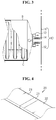
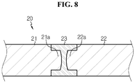
- FIGS. 4 through 8 are diagrams an example of construction of the fusing unit applied in the overcurrent shut-off device of FIG. 2 .
- the fusing unit 20 employed in the overcurrent shut-off device 100 may include a first metal plate 21, a second metal plate 22, and an alloy bridge 23.
- the metal plates 21 and 22 correspond to a thin plate-like metal, and are disposed side by side on the same plane with a spacing therebetween.
- the metal plates 21 and 22 are generally made from copper (Cu) or aluminum (Al), but the material for the metal plates 21 and 22 of the present disclosure is not limited thereto and various conductive metal materials may be applied.
- the material type may change based on a material of a component joined to the metal plates 21 and 22. That is, the same material for the metal plates 21 and 22 as the material for the component joined thereto may be advantageous in terms of welding performance improvement and contact resistance minimization.
- the metal plates 21 and 22 may be made from different materials based on the material for the component joined thereto.
- the alloy for the alloy bridge 23 has a lower melting point than the metal plates 21 and 22, for example, a melting point in a range of approximately 100°C to 250°C, and may include a lead-free alloy containing tin (Sn) and copper (Cu) as a main substance, without lead (Pb) which does harm to the environment and human body.
- the melting point range of the alloy for the alloy bridge 23 is set in consideration of a level of an overcurrent intended to interrupt.
- the melting point of the alloy is lower than 100°C, the alloy may be melted even when a normal electric current flows through the secondary battery to which the fusing unit 20 is applied.
- the melting point of the alloy is higher than 250°C, melting of the alloy is not made quickly and thus an overcurrent is not effectively interrupted.
- the alloy bridge 23 may further include, as an additional alloy substance, a metal having high electrical conductivity such as, for example, nickel (Ni), silver (Ag), zinc (Zn), and the like.
- a metal having high electrical conductivity such as, for example, nickel (Ni), silver (Ag), zinc (Zn), and the like.
- the content of the additional alloy substance is preferably in a range of approximately 0.01 wt% to 10 wt% based on the total weight of the alloy.
- the fusing unit 20 may have a quick rupture property in response to an overcurrent and have relatively high conductivity.
- the metal plates 21 and 22 may have protrusive ends facing each other, so the alloy bridge 23 may have an approximately T-shaped cross section.
- the first metal plate 21 has a protrusive part 21a formed protrusively in an approximately perpendicular direction from a thickness-wise center of one end thereof
- the second metal plate 22 has a protrusive part 22a formed protrusively in an approximately perpendicular direction from a thickness-wise center of one end thereof.
- the pair of protrusive parts 21a and 22a face each other.
- a height H and a width W of the protrusive parts 21a and 22a influence on the characteristics of the fusing unit 20 such as electrical conductivity, safety against an overcurrent (ease of rupture), and tensile strength.
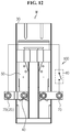
- facing surfaces S1 and S2 of each of the protrusive parts 21a and 22a may be formed in various shapes. That is, the facing surfaces S1 and S2 may be formed in a shape of a plane approximately perpendicular to the lengthwise direction of the metal plates 21 and 22, and may be parallel to each other (see FIG. 5 ) or may be inclined in opposite directions (see FIG. 6 ). Also, the facing surfaces S 1 and S2 may be formed protrusively in an approximately convex curve of an angled shape (see FIG. 7 ) or a round shape (see FIG. 8 ).
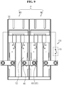
- FIG. 9 is a diagram illustrating a battery pack system to which the overcurrent shut-off device is applied according to an exemplary embodiment of the present disclosure
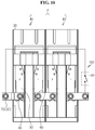
- FIG. 10 is a diagram illustrating a case in which the fusing unit applied in the overcurrent shut-off device is installed at a changed location, in the battery pack system of FIG. 9 .
- Each of the battery modules M1 and M2 includes at least one battery cell (not shown), a housing 30 where the battery cell is received, an external terminal 40 provided protrusively out of the housing 30, and a bus bar 50 connecting the battery cell to the external terminal 40, and the electrical connection between the battery modules M1 and M2 is established by an interconnecting bar 60.
- the switching unit 10 is disposed adjacent to a surface parallel to the battery cell among outer surfaces of the housing 30, and is turned on when a swelling phenomenon occurs.
- the drawing of the present disclosure illustrates only the case where the switching unit 10 is disposed adjacent to the outer surface of the battery pack P, the present disclosure is not limited thereto. That is, the switching unit 10 may perform a function for achieving the object of the present disclosure if the switching unit 10 is installed at a location where the switching unit 10 may be turned on in response to a swelling phenomenon, and thus may be disposed between the adjacent battery modules M1 and M2.
- the fusing unit 20 may be used as a component connecting the battery modules M1 and M2. That is, the battery pack system of FIG. 9 has a structure in which the fusing unit 20 is applied as the interconnecting bar 60.
- the location where the fusing unit 20 is applied is not limited thereto. That is, the fusing unit 20 may be applied as, for example, a lead terminal 70 which is connected to the external terminal 40 disposed at both ends of the battery pack P as shown in FIG. 10 , and besides, may replace various component installed on a path of an electric current flowing through the battery pack P such as the bus bar 50 and the like.
- FIG. 11 is a diagram illustrating a battery module system to which the overcurrent shut-off device is applied according to an exemplary embodiment of the present disclosure
- FIG. 12 is a diagram illustrating a case in which the fusing unit applied in the overcurrent shut-off device is installed at a changed location, in the battery module system of FIG. 11 .
- the battery module system includes a battery module M being substantially the same as the battery modules M1 and M2 previously described, and the overcurrent shut-off device 100 according to the present disclosure applied thereto.
- the fusing unit 20 may be used as a component connecting the battery cell to the external terminal 40. That is, the battery module system of FIG. 11 has a structure in which the fusing unit 20 is applied as the bus bar 50.
- the location where the fusing unit 20 is applied is not limited thereto. That is, the fusing unit 20 may be applied as, for example, a lead terminal 70 which is connected to the external terminal 40 disposed at both ends of the battery module M as shown in FIG. 12 , and besides, may replace various component installed on a path of an electric current flowing through the battery module M.
- the overcurrent shut-off device 100 may interrupt the path of the electric current flowing through the secondary battery quickly.
- the secondary battery system equipped with the overcurrent shut-off device 100 reduces in a fire/explosion risk caused by overheat, thereby ensuring safety of the secondary battery in use.
Landscapes
- Chemical & Material Sciences (AREA)
- General Chemical & Material Sciences (AREA)
- Chemical Kinetics & Catalysis (AREA)
- Electrochemistry (AREA)
- Engineering & Computer Science (AREA)
- Power Engineering (AREA)
- Manufacturing & Machinery (AREA)
- Materials Engineering (AREA)
- Connection Of Batteries Or Terminals (AREA)
- Battery Mounting, Suspending (AREA)
- Protection Of Static Devices (AREA)
- Fuses (AREA)
- Charge And Discharge Circuits For Batteries Or The Like (AREA)
- Emergency Protection Circuit Devices (AREA)
Claims (15)
- Überstromabschaltvorrichtung, welche aufweist:eine Schalteinheit, die mit beiden Enden einer Sekundärbatterie verbunden ist, wobei die Schalteinheit durch Druck eingeschaltet wird, der durch ein in der Sekundärbatterie auftretendes Schwellphänomen hervorgerufen wird;eine Sicherungseinheit, die als Komponente, die an einem Weg eines durch die Sekundärbatterie fließenden elektrischen Stroms angebracht ist, durchbrochen wird, wenn die Schalteinheit eingeschaltet wird, um den durch die Sekundärbatterie fließenden elektrischen Strom zu unterbrochen, wobei die Schalteinheit aufweist:- eine erste Leiterplatte, die mit einer ersten Elektrode der Sekundärbatterie elektrisch verbunden ist;- eine zweite Leiterplatte, die mit einer zweiten Elektrode der Sekundärbatterie elektrisch verbunden und von der ersten Leiterplatte beabstandet ist; und- eine dritte Leiterplatte, die von der ersten Leiterplatte und von der zweiten Leiterplatte beabstandet ist, wobei die dritte Leiterplatte durch den während des Schwellphänomens angelegten Druck mit der ersten Leiterplatte und der zweiten Leiterplatte in Kontakt kommt.
- Die Überstromabschaltvorrichtung nach Anspruch 1, wobei die Sekundärbatterie zumindest eine Batteriezelle enthält.
- Die Überstromabschaltvorrichtung nach Anspruch 2, wobei die Schalteinheit benachbart einer zur Batteriezelle parallelen Oberfläche unter Außenoberflächen der Sekundärbatterie anbeordnet ist.
- Die Überstrarrmabschaltvorrichtung nach Anspruch 1, wobei die Sicherungseinheit aufweist:eine erste Metallplatte;eine zweite Metallplatte, die mit einem Abstand dazwischen von der ersten Metallplatte beabstandet ist; undeine Legierungsbrücke, die einen niedrigeren Schmelzpunkt als die erste Metallplatte und die zweite Metallplatte aufweist, wobei die Legierungsbrücke den Abstand füllt.
- Die Überstromabschaltvorrichtung nach Anspruch 4, wobei die erste Metallplatte und die zweite Metallplatte auf derselben Ebene nebeneinander angeordnet sind.
- Die Überstromabschaltvorrichtung nach Anspruch 5, wobei eine Oberfläche der Legierungsbrücke dieselbe Ebene mit Oberflächen der ersten Metallplatte und der zweiten Metallplatte bildet.
- Die Überstromabschaltvorrichtung nach Anspruch 4, wobei die erste Metallplatte ein erstes vorstehendes Teil aufweist, das von einer dickenmäßigen Mitte eines Endes vorsteht, und die zweite Metallplatte ein zweites vorstehendes Teil aufweist, das von einer dickenmäßigen Mitte eines Endes vorsteht und dem ersten vorstehenden Teil gegenüberliegt.
- Die Überstromabschaltvorrichtung nach Anspruch 7, wobei jedes vom ersten vorstehenden Teil und zweiten vorstehenden Teil gegenüberliegende Oberflächen hat, die parallel zueinander ausgebildet sind.
- Die Überstromabschaltvarrichtung nach Anspruch 7, wobei jedes vom ersten vorstehenden Teil und zweiten vorstehenden Teil gegenüberliegende Oberflächen aufweist, die in entgegengesetzte Richtungen schräg ausgebildet sind.
- Die Überstromabschaltvorrichtung nach Anspruch 7, wobei jedes vom ersten vorstehenden Teil und zweiten vorstehenden Teil einander gegenüberliegende Oberflächen aufweist, die zueinander konvex vorstehend ausgebildet sind.
- Die Überstromabschaltvorrichtung nach Anspruch 10, wobei jede der einander gegentiberliegenden Oberflächen eine gewinkelte Form oder runde Form aufweist.
- Die Überstromabschaltvorrichtung nach Anspruch 4, wobei die Legierungsbrücke aus bleifreier Legierung hergestellt ist, welche Zinn und Kupfer enthält.
- Die Überstromabschaltvorrichtung nach Anspruch 12, wobei ein Gehalt des Zinns im Bereich von 80 Gewichtsprozent bis 98 Gewichtsprozent liegt, und ein Gehalt des Kupfers im Bereich von 2 Gewichtsprozent bis 20 Gewichtsprozent liegt, basierend auf einem Gesamtgewicht der bleifreien Legierung.
- Die Überstromabschaltvorrichtung nach Anspruch 13, wobei die bleifreie Legierung ferner zumindest ein zusätzliches Metall enthält, das aus Nickel, Zink und Silber ausgewählt ist.
- Die Überstrtamabschaltvorrichtung nach Anspruch 14, wobei ein Gehalt des zusätzlichen Metalls im Bereich von 0,01 Gewichtsprozent bis 10 Gewichtsprozent liegt, basierend auf dem Gesamtgewicht der bleifreien Legierung.
Applications Claiming Priority (2)
| Application Number | Priority Date | Filing Date | Title |
|---|---|---|---|
| KR1020130055326A KR101690295B1 (ko) | 2013-05-15 | 2013-05-15 | 과전류 차단 장치 및 이를 포함하는 이차전지 시스템 |
| PCT/KR2014/004156 WO2014185662A1 (ko) | 2013-05-15 | 2014-05-09 | 과전류 차단 장치 및 이를 포함하는 이차전지 시스템 |
Publications (3)
| Publication Number | Publication Date |
|---|---|
| EP2911218A1 EP2911218A1 (de) | 2015-08-26 |
| EP2911218A4 EP2911218A4 (de) | 2016-06-29 |
| EP2911218B1 true EP2911218B1 (de) | 2017-11-01 |
Family
ID=51898595
Family Applications (1)
| Application Number | Title | Priority Date | Filing Date |
|---|---|---|---|
| EP14797554.4A Active EP2911218B1 (de) | 2013-05-15 | 2014-05-09 | Überstromblockierungsvorrichtung und sekundärbatteriesystem damit |
Country Status (6)
| Country | Link |
|---|---|
| US (1) | US9444088B2 (de) |
| EP (1) | EP2911218B1 (de) |
| JP (1) | JP6067923B2 (de) |
| KR (1) | KR101690295B1 (de) |
| CN (1) | CN104756282B (de) |
| WO (1) | WO2014185662A1 (de) |
Families Citing this family (14)
| Publication number | Priority date | Publication date | Assignee | Title |
|---|---|---|---|---|
| KR102372818B1 (ko) * | 2014-12-30 | 2022-03-11 | 에이치그린파워 주식회사 | 과충전 방지 장치 및 방법 |
| US10763487B2 (en) | 2015-07-23 | 2020-09-01 | Contemporary Amperex Technology Co., Limited | Power battery cap structure and power battery |
| CN106935740B (zh) * | 2015-07-23 | 2019-12-20 | 宁德时代新能源科技股份有限公司 | 动力电池顶盖结构及动力电池 |
| KR101937716B1 (ko) | 2015-09-10 | 2019-01-14 | 주식회사 엘지화학 | 전지팩 |
| KR102325844B1 (ko) * | 2016-10-21 | 2021-11-11 | 삼성에스디아이 주식회사 | 이차 전지 |
| CN107482140B (zh) * | 2017-08-11 | 2023-07-25 | 中山市润烨新能源科技有限公司 | 一种外置双保险保护装置的电池盖板 |
| KR20190126528A (ko) * | 2018-05-02 | 2019-11-12 | 현대자동차주식회사 | 차량용 에너지 저장장치 시스템 |
| US11355824B2 (en) | 2018-05-11 | 2022-06-07 | The Regents Of The University Of Michigan | Detection of an internal short circuit in a battery |
| EP3591739A1 (de) * | 2018-07-03 | 2020-01-08 | Hilti Aktiengesellschaft | Sicherheitseinrichtung für batteriepacks mit pouchzellen durch mechanische stromunterbrecher |
| EP3664179A1 (de) * | 2018-12-05 | 2020-06-10 | Hilti Aktiengesellschaft | Akkupackvorrichtung und verfahren zum betreiben der akkupackvorrichtung |
| CN111352035A (zh) * | 2018-12-20 | 2020-06-30 | 技嘉科技股份有限公司 | 可检测电池膨胀的电子装置与电池膨胀 |
| CN114614202A (zh) * | 2022-03-29 | 2022-06-10 | 东莞新能安科技有限公司 | 电池包及用电设备 |
| FR3137225B1 (fr) * | 2022-06-22 | 2024-06-28 | Commissariat A L Energie Atomique Et Aux Energies Alternatives | Dispositif et procédé d’isolement d’accumulateur électrique à réserve de matière conductrice fusible |
| KR102696752B1 (ko) * | 2024-04-18 | 2024-08-22 | 주식회사 브랜드뉴 | 누전 경보 시스템 |
Family Cites Families (18)
| Publication number | Priority date | Publication date | Assignee | Title |
|---|---|---|---|---|
| JP4146912B2 (ja) * | 1997-01-30 | 2008-09-10 | Fdk株式会社 | 安全機構付き二次電池 |
| EP1300867A1 (de) * | 2001-10-03 | 2003-04-09 | Metalor Technologies International S.A. | Sicherungseinsatz und Herstellungsverfahren |
| KR100521477B1 (ko) * | 2003-06-18 | 2005-10-12 | 삼성에스디아이 주식회사 | 이차 전지 |
| KR100601533B1 (ko) * | 2004-07-28 | 2006-07-19 | 삼성에스디아이 주식회사 | 이차전지용 이차보호소자 |
| CN100570928C (zh) * | 2005-09-07 | 2009-12-16 | 株式会社Lg化学 | 使用安全元件的二次电池 |
| US20070099073A1 (en) * | 2005-10-31 | 2007-05-03 | White Daniel J | Cell connection straps for battery cells of a battery pack |
| JP5105394B2 (ja) * | 2006-03-15 | 2012-12-26 | 日立ビークルエナジー株式会社 | 電池ユニット |
| JP5176427B2 (ja) * | 2007-08-20 | 2013-04-03 | 株式会社Gsユアサ | 密閉型蓄電池 |
| US20090159354A1 (en) * | 2007-12-25 | 2009-06-25 | Wenfeng Jiang | Battery system having interconnected battery packs each having multiple electrochemical storage cells |
| JP2010135148A (ja) * | 2008-12-03 | 2010-06-17 | Nissan Motor Co Ltd | セルユニット、電池モジュール、および組電池 |
| US8236439B2 (en) * | 2009-08-14 | 2012-08-07 | Sb Limotive Co., Ltd. | Rechargeable battery |
| US8877361B2 (en) * | 2009-09-01 | 2014-11-04 | Samsung Sdi Co., Ltd. | Rechargeable battery |
| US8753765B2 (en) | 2011-03-14 | 2014-06-17 | Samsung Sdi Co., Ltd. | Secondary battery |
| JP5804540B2 (ja) * | 2011-05-17 | 2015-11-04 | エルジー ケム. エルティーディ. | 安全性の向上した電池パック |
| EP2672549B1 (de) * | 2011-06-17 | 2017-11-15 | LG Chem, Ltd. | Sekundärbatterie und mehrbatteriesystem umfassend ein verbindungselement |
| KR101383167B1 (ko) * | 2011-10-20 | 2014-04-10 | 주식회사 엘지화학 | 안전성이 향상된 전지팩 |
| KR101715954B1 (ko) * | 2011-11-07 | 2017-03-14 | 삼성에스디아이 주식회사 | 이차 전지 |
| JP6194572B2 (ja) * | 2012-10-15 | 2017-09-13 | 株式会社Gsユアサ | 蓄電素子及び電源モジュール |
-
2013
- 2013-05-15 KR KR1020130055326A patent/KR101690295B1/ko active Active
-
2014
- 2014-05-09 EP EP14797554.4A patent/EP2911218B1/de active Active
- 2014-05-09 WO PCT/KR2014/004156 patent/WO2014185662A1/ko not_active Ceased
- 2014-05-09 JP JP2016505419A patent/JP6067923B2/ja active Active
- 2014-05-09 CN CN201480002857.5A patent/CN104756282B/zh active Active
- 2014-10-23 US US14/521,559 patent/US9444088B2/en active Active
Non-Patent Citations (1)
| Title |
|---|
| None * |
Also Published As
| Publication number | Publication date |
|---|---|
| JP6067923B2 (ja) | 2017-01-25 |
| CN104756282B (zh) | 2017-06-23 |
| US9444088B2 (en) | 2016-09-13 |
| CN104756282A (zh) | 2015-07-01 |
| EP2911218A1 (de) | 2015-08-26 |
| KR101690295B1 (ko) | 2017-01-09 |
| EP2911218A4 (de) | 2016-06-29 |
| KR20140135054A (ko) | 2014-11-25 |
| US20150044528A1 (en) | 2015-02-12 |
| JP2016520954A (ja) | 2016-07-14 |
| WO2014185662A1 (ko) | 2014-11-20 |
Similar Documents
| Publication | Publication Date | Title |
|---|---|---|
| EP2911218B1 (de) | Überstromblockierungsvorrichtung und sekundärbatteriesystem damit | |
| EP2950371B1 (de) | Sekundärbatterie und elektrodenkabelanordnung dafür | |
| EP2887430B1 (de) | Verbindungselement für sekundärbatterie und sekundärbatterie damit | |
| US9577240B2 (en) | Battery module and bus bar applied to battery module | |
| CN103650209B (zh) | 电池组和应用于该电池组的连接条 | |
| US8890648B2 (en) | Connecting element for secondary battery, and battery module and battery pack including the same | |
| KR101812273B1 (ko) | 전류 차단용 버스 바를 구비하는 배터리 모듈 | |
| KR101614434B1 (ko) | 안전성이 향상된 배터리 셀 | |
| KR20140064093A (ko) | 안전성이 향상된 배터리 모듈 및 이에 적용되는 버스 바 | |
| KR20140110190A (ko) | 이차전지용 안전 킷 및 이를 포함하는 이차전지 | |
| KR20140011206A (ko) | 이차전지용 커넥팅 부품, 이를 포함하는 배터리 모듈 및 배터리 팩 |
Legal Events
| Date | Code | Title | Description |
|---|---|---|---|
| PUAI | Public reference made under article 153(3) epc to a published international application that has entered the european phase |
Free format text: ORIGINAL CODE: 0009012 |
|
| 17P | Request for examination filed |
Effective date: 20150424 |
|
| AK | Designated contracting states |
Kind code of ref document: A1 Designated state(s): AL AT BE BG CH CY CZ DE DK EE ES FI FR GB GR HR HU IE IS IT LI LT LU LV MC MK MT NL NO PL PT RO RS SE SI SK SM TR |
|
| AX | Request for extension of the european patent |
Extension state: BA ME |
|
| RA4 | Supplementary search report drawn up and despatched (corrected) |
Effective date: 20160530 |
|
| RIC1 | Information provided on ipc code assigned before grant |
Ipc: H02H 3/02 20060101ALI20160523BHEP Ipc: H02H 7/18 20060101ALI20160523BHEP Ipc: H01M 2/10 20060101AFI20160523BHEP Ipc: H02H 3/087 20060101ALI20160523BHEP Ipc: H01M 10/052 20100101ALI20160523BHEP Ipc: H02J 7/00 20060101ALI20160523BHEP Ipc: H01M 2/34 20060101ALI20160523BHEP |
|
| DAX | Request for extension of the european patent (deleted) | ||
| GRAP | Despatch of communication of intention to grant a patent |
Free format text: ORIGINAL CODE: EPIDOSNIGR1 |
|
| STAA | Information on the status of an ep patent application or granted ep patent |
Free format text: STATUS: GRANT OF PATENT IS INTENDED |
|
| INTG | Intention to grant announced |
Effective date: 20170809 |
|
| GRAS | Grant fee paid |
Free format text: ORIGINAL CODE: EPIDOSNIGR3 |
|
| GRAA | (expected) grant |
Free format text: ORIGINAL CODE: 0009210 |
|
| STAA | Information on the status of an ep patent application or granted ep patent |
Free format text: STATUS: THE PATENT HAS BEEN GRANTED |
|
| AK | Designated contracting states |
Kind code of ref document: B1 Designated state(s): AL AT BE BG CH CY CZ DE DK EE ES FI FR GB GR HR HU IE IS IT LI LT LU LV MC MK MT NL NO PL PT RO RS SE SI SK SM TR |
|
| REG | Reference to a national code |
Ref country code: GB Ref legal event code: FG4D |
|
| REG | Reference to a national code |
Ref country code: CH Ref legal event code: EP Ref country code: AT Ref legal event code: REF Ref document number: 942862 Country of ref document: AT Kind code of ref document: T Effective date: 20171115 |
|
| REG | Reference to a national code |
Ref country code: IE Ref legal event code: FG4D |
|
| REG | Reference to a national code |
Ref country code: DE Ref legal event code: R096 Ref document number: 602014016712 Country of ref document: DE |
|
| REG | Reference to a national code |
Ref country code: NL Ref legal event code: MP Effective date: 20171101 |
|
| REG | Reference to a national code |
Ref country code: LT Ref legal event code: MG4D |
|
| REG | Reference to a national code |
Ref country code: AT Ref legal event code: MK05 Ref document number: 942862 Country of ref document: AT Kind code of ref document: T Effective date: 20171101 |
|
| REG | Reference to a national code |
Ref country code: FR Ref legal event code: PLFP Year of fee payment: 5 |
|
| PG25 | Lapsed in a contracting state [announced via postgrant information from national office to epo] |
Ref country code: ES Free format text: LAPSE BECAUSE OF FAILURE TO SUBMIT A TRANSLATION OF THE DESCRIPTION OR TO PAY THE FEE WITHIN THE PRESCRIBED TIME-LIMIT Effective date: 20171101 Ref country code: NO Free format text: LAPSE BECAUSE OF FAILURE TO SUBMIT A TRANSLATION OF THE DESCRIPTION OR TO PAY THE FEE WITHIN THE PRESCRIBED TIME-LIMIT Effective date: 20180201 Ref country code: SE Free format text: LAPSE BECAUSE OF FAILURE TO SUBMIT A TRANSLATION OF THE DESCRIPTION OR TO PAY THE FEE WITHIN THE PRESCRIBED TIME-LIMIT Effective date: 20171101 Ref country code: LT Free format text: LAPSE BECAUSE OF FAILURE TO SUBMIT A TRANSLATION OF THE DESCRIPTION OR TO PAY THE FEE WITHIN THE PRESCRIBED TIME-LIMIT Effective date: 20171101 Ref country code: NL Free format text: LAPSE BECAUSE OF FAILURE TO SUBMIT A TRANSLATION OF THE DESCRIPTION OR TO PAY THE FEE WITHIN THE PRESCRIBED TIME-LIMIT Effective date: 20171101 Ref country code: FI Free format text: LAPSE BECAUSE OF FAILURE TO SUBMIT A TRANSLATION OF THE DESCRIPTION OR TO PAY THE FEE WITHIN THE PRESCRIBED TIME-LIMIT Effective date: 20171101 |
|
| PG25 | Lapsed in a contracting state [announced via postgrant information from national office to epo] |
Ref country code: RS Free format text: LAPSE BECAUSE OF FAILURE TO SUBMIT A TRANSLATION OF THE DESCRIPTION OR TO PAY THE FEE WITHIN THE PRESCRIBED TIME-LIMIT Effective date: 20171101 Ref country code: GR Free format text: LAPSE BECAUSE OF FAILURE TO SUBMIT A TRANSLATION OF THE DESCRIPTION OR TO PAY THE FEE WITHIN THE PRESCRIBED TIME-LIMIT Effective date: 20180202 Ref country code: HR Free format text: LAPSE BECAUSE OF FAILURE TO SUBMIT A TRANSLATION OF THE DESCRIPTION OR TO PAY THE FEE WITHIN THE PRESCRIBED TIME-LIMIT Effective date: 20171101 Ref country code: BG Free format text: LAPSE BECAUSE OF FAILURE TO SUBMIT A TRANSLATION OF THE DESCRIPTION OR TO PAY THE FEE WITHIN THE PRESCRIBED TIME-LIMIT Effective date: 20180201 Ref country code: IS Free format text: LAPSE BECAUSE OF FAILURE TO SUBMIT A TRANSLATION OF THE DESCRIPTION OR TO PAY THE FEE WITHIN THE PRESCRIBED TIME-LIMIT Effective date: 20180301 Ref country code: LV Free format text: LAPSE BECAUSE OF FAILURE TO SUBMIT A TRANSLATION OF THE DESCRIPTION OR TO PAY THE FEE WITHIN THE PRESCRIBED TIME-LIMIT Effective date: 20171101 Ref country code: AT Free format text: LAPSE BECAUSE OF FAILURE TO SUBMIT A TRANSLATION OF THE DESCRIPTION OR TO PAY THE FEE WITHIN THE PRESCRIBED TIME-LIMIT Effective date: 20171101 |
|
| PG25 | Lapsed in a contracting state [announced via postgrant information from national office to epo] |
Ref country code: DK Free format text: LAPSE BECAUSE OF FAILURE TO SUBMIT A TRANSLATION OF THE DESCRIPTION OR TO PAY THE FEE WITHIN THE PRESCRIBED TIME-LIMIT Effective date: 20171101 Ref country code: CZ Free format text: LAPSE BECAUSE OF FAILURE TO SUBMIT A TRANSLATION OF THE DESCRIPTION OR TO PAY THE FEE WITHIN THE PRESCRIBED TIME-LIMIT Effective date: 20171101 Ref country code: EE Free format text: LAPSE BECAUSE OF FAILURE TO SUBMIT A TRANSLATION OF THE DESCRIPTION OR TO PAY THE FEE WITHIN THE PRESCRIBED TIME-LIMIT Effective date: 20171101 Ref country code: CY Free format text: LAPSE BECAUSE OF FAILURE TO SUBMIT A TRANSLATION OF THE DESCRIPTION OR TO PAY THE FEE WITHIN THE PRESCRIBED TIME-LIMIT Effective date: 20171101 Ref country code: SK Free format text: LAPSE BECAUSE OF FAILURE TO SUBMIT A TRANSLATION OF THE DESCRIPTION OR TO PAY THE FEE WITHIN THE PRESCRIBED TIME-LIMIT Effective date: 20171101 |
|
| REG | Reference to a national code |
Ref country code: DE Ref legal event code: R097 Ref document number: 602014016712 Country of ref document: DE |
|
| PG25 | Lapsed in a contracting state [announced via postgrant information from national office to epo] |
Ref country code: SM Free format text: LAPSE BECAUSE OF FAILURE TO SUBMIT A TRANSLATION OF THE DESCRIPTION OR TO PAY THE FEE WITHIN THE PRESCRIBED TIME-LIMIT Effective date: 20171101 Ref country code: PL Free format text: LAPSE BECAUSE OF FAILURE TO SUBMIT A TRANSLATION OF THE DESCRIPTION OR TO PAY THE FEE WITHIN THE PRESCRIBED TIME-LIMIT Effective date: 20171101 Ref country code: RO Free format text: LAPSE BECAUSE OF FAILURE TO SUBMIT A TRANSLATION OF THE DESCRIPTION OR TO PAY THE FEE WITHIN THE PRESCRIBED TIME-LIMIT Effective date: 20171101 Ref country code: IT Free format text: LAPSE BECAUSE OF FAILURE TO SUBMIT A TRANSLATION OF THE DESCRIPTION OR TO PAY THE FEE WITHIN THE PRESCRIBED TIME-LIMIT Effective date: 20171101 |
|
| PLBE | No opposition filed within time limit |
Free format text: ORIGINAL CODE: 0009261 |
|
| STAA | Information on the status of an ep patent application or granted ep patent |
Free format text: STATUS: NO OPPOSITION FILED WITHIN TIME LIMIT |
|
| 26N | No opposition filed |
Effective date: 20180802 |
|
| PG25 | Lapsed in a contracting state [announced via postgrant information from national office to epo] |
Ref country code: SI Free format text: LAPSE BECAUSE OF FAILURE TO SUBMIT A TRANSLATION OF THE DESCRIPTION OR TO PAY THE FEE WITHIN THE PRESCRIBED TIME-LIMIT Effective date: 20171101 |
|
| REG | Reference to a national code |
Ref country code: CH Ref legal event code: PL |
|
| REG | Reference to a national code |
Ref country code: BE Ref legal event code: MM Effective date: 20180531 |
|
| PG25 | Lapsed in a contracting state [announced via postgrant information from national office to epo] |
Ref country code: MC Free format text: LAPSE BECAUSE OF FAILURE TO SUBMIT A TRANSLATION OF THE DESCRIPTION OR TO PAY THE FEE WITHIN THE PRESCRIBED TIME-LIMIT Effective date: 20171101 |
|
| REG | Reference to a national code |
Ref country code: IE Ref legal event code: MM4A |
|
| PG25 | Lapsed in a contracting state [announced via postgrant information from national office to epo] |
Ref country code: LI Free format text: LAPSE BECAUSE OF NON-PAYMENT OF DUE FEES Effective date: 20180531 Ref country code: CH Free format text: LAPSE BECAUSE OF NON-PAYMENT OF DUE FEES Effective date: 20180531 |
|
| PG25 | Lapsed in a contracting state [announced via postgrant information from national office to epo] |
Ref country code: LU Free format text: LAPSE BECAUSE OF NON-PAYMENT OF DUE FEES Effective date: 20180509 |
|
| PG25 | Lapsed in a contracting state [announced via postgrant information from national office to epo] |
Ref country code: IE Free format text: LAPSE BECAUSE OF NON-PAYMENT OF DUE FEES Effective date: 20180509 |
|
| PG25 | Lapsed in a contracting state [announced via postgrant information from national office to epo] |
Ref country code: BE Free format text: LAPSE BECAUSE OF NON-PAYMENT OF DUE FEES Effective date: 20180531 |
|
| PG25 | Lapsed in a contracting state [announced via postgrant information from national office to epo] |
Ref country code: MT Free format text: LAPSE BECAUSE OF NON-PAYMENT OF DUE FEES Effective date: 20180509 |
|
| PG25 | Lapsed in a contracting state [announced via postgrant information from national office to epo] |
Ref country code: TR Free format text: LAPSE BECAUSE OF FAILURE TO SUBMIT A TRANSLATION OF THE DESCRIPTION OR TO PAY THE FEE WITHIN THE PRESCRIBED TIME-LIMIT Effective date: 20171101 |
|
| PG25 | Lapsed in a contracting state [announced via postgrant information from national office to epo] |
Ref country code: PT Free format text: LAPSE BECAUSE OF FAILURE TO SUBMIT A TRANSLATION OF THE DESCRIPTION OR TO PAY THE FEE WITHIN THE PRESCRIBED TIME-LIMIT Effective date: 20171101 |
|
| PG25 | Lapsed in a contracting state [announced via postgrant information from national office to epo] |
Ref country code: MK Free format text: LAPSE BECAUSE OF NON-PAYMENT OF DUE FEES Effective date: 20171101 Ref country code: HU Free format text: LAPSE BECAUSE OF FAILURE TO SUBMIT A TRANSLATION OF THE DESCRIPTION OR TO PAY THE FEE WITHIN THE PRESCRIBED TIME-LIMIT; INVALID AB INITIO Effective date: 20140509 |
|
| PG25 | Lapsed in a contracting state [announced via postgrant information from national office to epo] |
Ref country code: AL Free format text: LAPSE BECAUSE OF FAILURE TO SUBMIT A TRANSLATION OF THE DESCRIPTION OR TO PAY THE FEE WITHIN THE PRESCRIBED TIME-LIMIT Effective date: 20171101 |
|
| REG | Reference to a national code |
Ref country code: DE Ref legal event code: R079 Ref document number: 602014016712 Country of ref document: DE Free format text: PREVIOUS MAIN CLASS: H01M0002100000 Ipc: H01M0050200000 |
|
| REG | Reference to a national code |
Ref country code: DE Ref legal event code: R081 Ref document number: 602014016712 Country of ref document: DE Owner name: LG ENERGY SOLUTION LTD., KR Free format text: FORMER OWNER: LG CHEM. LTD., SEOUL, KR Ref country code: DE Ref legal event code: R081 Ref document number: 602014016712 Country of ref document: DE Owner name: LG ENERGY SOLUTION, LTD., KR Free format text: FORMER OWNER: LG CHEM. LTD., SEOUL, KR |
|
| P01 | Opt-out of the competence of the unified patent court (upc) registered |
Effective date: 20230512 |
|
| REG | Reference to a national code |
Ref country code: GB Ref legal event code: 732E Free format text: REGISTERED BETWEEN 20230824 AND 20230831 |
|
| REG | Reference to a national code |
Ref country code: DE Ref legal event code: R081 Ref document number: 602014016712 Country of ref document: DE Owner name: LG ENERGY SOLUTION, LTD., KR Free format text: FORMER OWNER: LG ENERGY SOLUTION LTD., SEOUL, KR |
|
| PGFP | Annual fee paid to national office [announced via postgrant information from national office to epo] |
Ref country code: DE Payment date: 20250422 Year of fee payment: 12 |
|
| PGFP | Annual fee paid to national office [announced via postgrant information from national office to epo] |
Ref country code: FR Payment date: 20250422 Year of fee payment: 12 |
|
| PGFP | Annual fee paid to national office [announced via postgrant information from national office to epo] |
Ref country code: GB Payment date: 20260324 Year of fee payment: 13 |