EP2911219B1 - Bloc-batteries - Google Patents
Bloc-batteries Download PDFInfo
- Publication number
- EP2911219B1 EP2911219B1 EP15155438.3A EP15155438A EP2911219B1 EP 2911219 B1 EP2911219 B1 EP 2911219B1 EP 15155438 A EP15155438 A EP 15155438A EP 2911219 B1 EP2911219 B1 EP 2911219B1
- Authority
- EP
- European Patent Office
- Prior art keywords
- connector
- battery pack
- battery module
- battery
- controller
- Prior art date
- Legal status (The legal status is an assumption and is not a legal conclusion. Google has not performed a legal analysis and makes no representation as to the accuracy of the status listed.)
- Active
Links
Images



Classifications
-
- H—ELECTRICITY
- H01—ELECTRIC ELEMENTS
- H01M—PROCESSES OR MEANS, e.g. BATTERIES, FOR THE DIRECT CONVERSION OF CHEMICAL ENERGY INTO ELECTRICAL ENERGY
- H01M50/00—Constructional details or processes of manufacture of the non-active parts of electrochemical cells other than fuel cells, e.g. hybrid cells
- H01M50/20—Mountings; Secondary casings or frames; Racks, modules or packs; Suspension devices; Shock absorbers; Transport or carrying devices; Holders
-
- H—ELECTRICITY
- H01—ELECTRIC ELEMENTS
- H01M—PROCESSES OR MEANS, e.g. BATTERIES, FOR THE DIRECT CONVERSION OF CHEMICAL ENERGY INTO ELECTRICAL ENERGY
- H01M10/00—Secondary cells; Manufacture thereof
- H01M10/42—Methods or arrangements for servicing or maintenance of secondary cells or secondary half-cells
- H01M10/425—Structural combination with electronic components, e.g. electronic circuits integrated to the outside of the casing
- H01M10/4257—Smart batteries, e.g. electronic circuits inside the housing of the cells or batteries
-
- H—ELECTRICITY
- H01—ELECTRIC ELEMENTS
- H01M—PROCESSES OR MEANS, e.g. BATTERIES, FOR THE DIRECT CONVERSION OF CHEMICAL ENERGY INTO ELECTRICAL ENERGY
- H01M50/00—Constructional details or processes of manufacture of the non-active parts of electrochemical cells other than fuel cells, e.g. hybrid cells
- H01M50/10—Primary casings; Jackets or wrappings
- H01M50/183—Sealing members
- H01M50/186—Sealing members characterised by the disposition of the sealing members
-
- H—ELECTRICITY
- H01—ELECTRIC ELEMENTS
- H01M—PROCESSES OR MEANS, e.g. BATTERIES, FOR THE DIRECT CONVERSION OF CHEMICAL ENERGY INTO ELECTRICAL ENERGY
- H01M50/00—Constructional details or processes of manufacture of the non-active parts of electrochemical cells other than fuel cells, e.g. hybrid cells
- H01M50/50—Current conducting connections for cells or batteries
-
- H—ELECTRICITY
- H01—ELECTRIC ELEMENTS
- H01M—PROCESSES OR MEANS, e.g. BATTERIES, FOR THE DIRECT CONVERSION OF CHEMICAL ENERGY INTO ELECTRICAL ENERGY
- H01M50/00—Constructional details or processes of manufacture of the non-active parts of electrochemical cells other than fuel cells, e.g. hybrid cells
- H01M50/50—Current conducting connections for cells or batteries
- H01M50/528—Fixed electrical connections, i.e. not intended for disconnection
-
- H—ELECTRICITY
- H01—ELECTRIC ELEMENTS
- H01M—PROCESSES OR MEANS, e.g. BATTERIES, FOR THE DIRECT CONVERSION OF CHEMICAL ENERGY INTO ELECTRICAL ENERGY
- H01M10/00—Secondary cells; Manufacture thereof
- H01M10/42—Methods or arrangements for servicing or maintenance of secondary cells or secondary half-cells
- H01M10/425—Structural combination with electronic components, e.g. electronic circuits integrated to the outside of the casing
- H01M2010/4271—Battery management systems including electronic circuits, e.g. control of current or voltage to keep battery in healthy state, cell balancing
-
- H—ELECTRICITY
- H01—ELECTRIC ELEMENTS
- H01M—PROCESSES OR MEANS, e.g. BATTERIES, FOR THE DIRECT CONVERSION OF CHEMICAL ENERGY INTO ELECTRICAL ENERGY
- H01M2220/00—Batteries for particular applications
- H01M2220/20—Batteries in motive systems, e.g. vehicle, ship, plane
-
- H—ELECTRICITY
- H01—ELECTRIC ELEMENTS
- H01M—PROCESSES OR MEANS, e.g. BATTERIES, FOR THE DIRECT CONVERSION OF CHEMICAL ENERGY INTO ELECTRICAL ENERGY
- H01M50/00—Constructional details or processes of manufacture of the non-active parts of electrochemical cells other than fuel cells, e.g. hybrid cells
- H01M50/10—Primary casings; Jackets or wrappings
- H01M50/183—Sealing members
- H01M50/19—Sealing members characterised by the material
- H01M50/193—Organic material
-
- H—ELECTRICITY
- H01—ELECTRIC ELEMENTS
- H01M—PROCESSES OR MEANS, e.g. BATTERIES, FOR THE DIRECT CONVERSION OF CHEMICAL ENERGY INTO ELECTRICAL ENERGY
- H01M50/00—Constructional details or processes of manufacture of the non-active parts of electrochemical cells other than fuel cells, e.g. hybrid cells
- H01M50/20—Mountings; Secondary casings or frames; Racks, modules or packs; Suspension devices; Shock absorbers; Transport or carrying devices; Holders
- H01M50/204—Racks, modules or packs for multiple batteries or multiple cells
- H01M50/207—Racks, modules or packs for multiple batteries or multiple cells characterised by their shape
- H01M50/209—Racks, modules or packs for multiple batteries or multiple cells characterised by their shape adapted for prismatic or rectangular cells
-
- Y—GENERAL TAGGING OF NEW TECHNOLOGICAL DEVELOPMENTS; GENERAL TAGGING OF CROSS-SECTIONAL TECHNOLOGIES SPANNING OVER SEVERAL SECTIONS OF THE IPC; TECHNICAL SUBJECTS COVERED BY FORMER USPC CROSS-REFERENCE ART COLLECTIONS [XRACs] AND DIGESTS
- Y02—TECHNOLOGIES OR APPLICATIONS FOR MITIGATION OR ADAPTATION AGAINST CLIMATE CHANGE
- Y02E—REDUCTION OF GREENHOUSE GAS [GHG] EMISSIONS, RELATED TO ENERGY GENERATION, TRANSMISSION OR DISTRIBUTION
- Y02E60/00—Enabling technologies; Technologies with a potential or indirect contribution to GHG emissions mitigation
- Y02E60/10—Energy storage using batteries
Definitions
- the present invention relates to a battery pack.
- a high-power battery pack with high-energy density using a non-aqueous electrolyte has been developed.
- Such a high-power battery pack can be implemented in high voltage or high capacity by connecting a plurality of battery cells or modules in parallel or in series.
- a high power battery pack is used in driving a motor of a device requiring high power, for example, an electric vehicle.
- US 2012/301747 A1 discloses a battery pack comprising a housing separated by a partition into a section in which battery modules are located and a section in which a controller is located.
- US 2011/135970 A1 discloses battery modules and a circuit substrate module in which a connector is provided for connecting the sensor lines of battery modules to a circuit board via a partition.
- the present invention has been made keeping in mind the above problems occurring in the related art, and an objection of the present invention is to provide a battery pack which adopts a novel structure to enhance safety.
- a battery pack as set-out in Claim 1.
- a battery pack according to the present invention is advantageous in that the space in which the battery module is accommodated is separated from the space in which the controller is positioned, by means of the isolator portion, thus enhancing the safety of the battery pack.
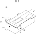
- FIG. 1 is a perspective view showing a battery pack 100a according to an embodiment of the present invention
- FIG. 2 is an exploded perspective view showing the battery pack 100a of FIG. 1 .
- the battery pack 100a according to this embodiment will be described with reference to FIGS. 1 and 2 .
- the battery pack 100a may include a battery module 110, a housing 120, a controller 130, an isolator portion 140 separating a space accommodating the battery module 110 from a space accommodating the controller 130, and a connector 150a (see FIG. 5 ) that passes through the isolator portion 140 to electrically connect the battery module 110 to the controller 130.
- the housing 120 is a member that accommodates the battery module 110 therein, and may include a body part 121 and a cover part 122.
- the body part 121 may be provided with a receiving part 126 to receive the battery module 110, and the cover part 122 may cover the body part 121. Further, the body part 121 may be provided with a first flange 123 and a first extension 124.
- the first flange 123 extends from a sidewall of the body part 121 in such a way as to be bent therefrom, and the first extension 124 extends from the first flange 123.
- the first extension 124 is coupled to a second extension 125 extending outwards from the cover part 122, thus allowing the body part 121 and the cover part 122 to be coupled with each other.
- the first extension 124 may extend from the first flange 123 in such a way as to be stepped. Such a configuration allows a second flange 141 of the isolator portion 140 which will be described below to be seated on the first flange 123 and fitted inside the first extension 124.
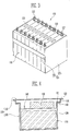
- FIG. 3 is a perspective view showing the battery module 110 of the battery pack 100a of FIG. 1 .
- the battery module 110 according to this embodiment will be described with reference to FIG. 3 .
- the battery module 110 according to this embodiment may include a plurality of battery cells 111, module busbars 117 electrically connecting the battery cells 111 to each other, and an alignment member 114 aligning the battery cells 111 with each other.
- the battery cell 111 is a member that generates energy.
- a plurality of battery cells may be provided.
- each battery cell 111 may include a battery case that is open at a surface thereof, and an electrode assembly and an electrolyte that are received in the battery case.
- the electrode assembly and the electrolyte electrochemically may react with each other to produce energy.
- a battery case may be sealed by a surface of the battery cell 111 including a cap assembly.
- terminals 112 having different polarities, namely, a positive terminal and a negative terminal may be provided on a surface of the battery cell 111 in such a way as to protrude therefrom.
- a vent part 113 may be further provided, which serves as a passage for discharging gas produced in the battery cell 111 to the outside.
- the plurality of battery cells 111 may be aligned in one direction.
- the battery cells 111 When the battery cells 111 are connected to each other in series, they may be arranged such that the terminals 112 of neighboring battery cells 111 have different polarities.
- the battery cells 111 when the battery cells 111 are connected to each other in parallel, they may be arranged such that the terminals 112 of neighboring battery cells 111 have the same polarity.
- the battery cells 111 may be aligned by the alignment member 114.
- the alignment member 114 includes a pair of end plates 115 disposed on the outermost battery cells 111 and a connection plate 116 connecting the end plates 115 to each other, thus allowing the battery cells 111 to be aligned in one direction.
- the module busbar 117 is a member that electrically connects the battery cells 111 to each other.
- the module busbar 117 is provided with a hole.
- a nut member 119 is fastened to the terminal 112, so that the module busbar 117 is electrically connected to the terminal 112 of the battery cell 111.
- the module busbar 117 may be coupled to the terminal 112 of the battery cell 111 by welding.
- the battery pack 100a may include at least one battery module 110.
- FIG. 4 is a sectional view showing the battery pack 100a taken along line A-A' of FIG. 1
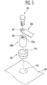
- FIG. 5 is an exploded perspective view showing the connector 150a and the isolator portion 140 of the battery pack 100a of FIG. 2 .
- the controller 130 and the isolator portion 140 according to this embodiment will be described with reference to FIGS. 4 and 5 .
- the controller 130 may be disposed on the isolator portion 140.
- the controller 130 may be positioned between the isolator portion 140 and the cover part 122 in such a way that a side thereof is surrounded with the body part 121 of the housing 120.
- the controller 130 may control and protect the battery module 110.
- a controller 130 may include at least one of a battery control unit (BCU), a battery management system (BMS), and a battery disconnect unit (BDU).
- BCU battery control unit
- BMS battery management system
- BDU battery disconnect unit
- the controller 130 may measure the voltage, SOC, temperature and others of the battery module 110 and then interrupt power when an abnormal phenomenon, such as overcurrent or overvoltage, occurs in the battery pack 100a.
- the controller 130 since the controller 130 includes electronic parts and circuits, the controller 130 may be especially susceptible to moisture. Thus, if the controller 130 and the battery module 110 are placed in the same space, the temperature of the battery module 110 may be abruptly changed, thus producing condensate water. The condensate water may negatively affect the controller 130 and thereby lead to the malfunction of the controller 130. Further, air for cooling the battery module 110 may negatively affect the controller 130, thus causing the malfunction of the controller 130.
- the battery module 110 according to this embodiment is separated from the controller 130 by means of the isolator portion 140, thus allowing the battery module 110 and the controller 130 to be positioned in separate independent spaces. Therefore, the controller 130 may be less affected by moisture or cooling air. Consequently, the safety of the battery pack 100a can be improved.
- the isolator portion 140 is a member that renders the battery module 110 and the controller 130 to be positioned in different independent spaces.
- the isolator portion 140 may be positioned between the battery module 110 and the controller 130.
- the isolator portion 140 may be positioned between the battery module 110 and the controller 130 to be covered by the cover part 122 of the housing 120.
- the second flange 141 may extend from a sidewall of the isolator portion 140 in such a way as to be bent therefrom, and may be superposed on the first flange 123 of the body part 121 of the housing 120.
- the body part 121 of the housing 120 may be coupled with the isolator portion 140 using a member, such as a bolt, passing through both the first and second flanges 123 and 141.
- the second flange 141 of the isolator portion 140 may overlap the first flange 123 in such a way as to be inside the first extension 124 of the body part 121. Since a step is provided between the first flange 123 and the first extension 124, the second flange 141 may be easily placed on the top of the first flange 123.
- the cover part 122 In the state where the body part 121 is coupled with the isolator portion 140, the cover part 122 is positioned thereabove.
- the second extension 125 of the cover part 122 may be fastened to the first extension 124 of the body part 121 via bolts, for example, thus allowing the body part 121, the isolator portion 140, and the cover part 122 to be fastened to each other.
- the isolator portion 140 is positioned between the battery module 110 and the controller 130, thus separating the space accommodating the battery module 110 from the space accommodating the controller 130 in such a way as to hermetically seal a gap between the spaces.
- the isolator portion 140 is made of an insulating material, thus preventing a short circuit from occurring between the battery module 110 and the controller 130.
- the insulating material may include at least one selected out from a group consisting of polyethylene, polypropylene and polycarbonate.
- the isolator portion 140 may be provided with a first opening 142 through which the connector 150a that will be described below passes.
- the first opening 142 may be larger than the connector 150a, and a sealing part 143 may be positioned between the first opening 142 and the connector 150a. That is, the sealing part 143 is positioned in the first opening 142, and a second opening 144 is formed in the sealing part 143, thus allowing the connector 150a to pass through the isolator portion 140 via the second opening 144.
- Such a sealing part 143 prevents the space accommodating the battery module 110 and the space in which the controller 130 is positioned from communicating with each other via the first opening 142, thus sealing both the spaces against each other.
- FIG. 6 is a sectional view showing the battery pack 100a taken along line B-B' of FIG. 1
- FIG. 7 is a perspective view showing the connector 150a of the battery pack 100a of FIG. 1 .
- the connector 150a according to this embodiment will be described with reference to FIGS. 5 to 7 .
- the connector 150a passes through the isolator portion 140 to electrically connect the battery module 110 to the controller 130.
- the connector 150a may pass through the first opening 142 of the isolator portion 140, or may pass through the second opening 144 formed in the sealing part 143 if the sealing part 143 is present.
- the second opening 144 may be smaller than the connector 150a, so that the connector 150a may be press-fitted into the second opening 144.
- the sealing part 143 may be made of an elastic material, for example, rubber.
- the connector 150a may electrically connect the battery module 110 to the controller 130.
- the meaning of 'electrically connected' will suffice as long as an electric current flows between the members even if they are connected to each other via another member, without being limited to the state where two members are physically connected to each other. That is, both the case where the connector 150a is directly connected to the controller 130 and the case where the connector 150a is connected to the controller 130 via the busbar 160 will be considered as the connector 150a being electrically connected to the controller 130.
- the case where the connector 150a is connected to the controller 130 via the busbar 160 will be described below. However, the present invention is not limited thereto.
- the power or condition of the battery module 110 may be transmitted to the controller 130 through the connector 150a.
- the controller 130 may control the battery module 110 through the connector 150a.
- the connector 150a electrically connects the battery module 110 to the controller 130, it may include a material having high electrical conductivity, for example, gold, silver, copper, or nickel. Further, the connector 150a may have a cylindrical shape. In this case, when the connector 150a is press-fitted into the sealing part 143, stress acting on each region may be constant, thus enhancing the sealing force of the sealing part 143.
- the connector 150a may be formed in the shape of a pillar having an insert part 151a therein.
- a first insert part 152a may be formed on a first side of the connector 150a
- a second insert part 153a may be formed on a second side of the connector 150a that is opposite to the first side.
- the first insert part 152a may be opened towards the battery module 110, while the second insert part 153a may be opened in an opposite direction.
- threads 154 may be formed on an inner wall of the connector 150a in which the insert part 151a including the first insert part 152a and the second insert part 153a is formed.
- the terminal 112 of the battery module 110 is inserted into the first insert part 152a to be fastened to the threads 154, so that the terminal 112 and the connector 150a may be electrically connected to each other through a threaded fastening portion.
- the terminal 112 fastened to the connector 150a may be the terminal 112 in which the high current of the battery module 110 flows.
- a coupling member 170 such as a bolt, may be inserted into the second insert part 153a to be fastened thereto by the threaded fastening method.
- a through hole 161 may be formed at a position on the busbar 160 that is situated adjacent to the second side of the connector 150a, in such a way as to correspond to the second insert part 153a.
- the coupling member 170 passes through the through hole 161 to be inserted into the second insert part 153a and then fastened to the connector 150a, thus allowing the connector 150a and the busbar 160 to be firmly coupled to each other and electrically connected to each other. Therefore, the signal indicating the state of the battery module 110 and power may be transmitted through the connector 150a and the busbar 160 to the controller 130.
- the insert part 151a is provided in the connector 150a, so that the connector 150a, the terminal 112, the coupling member 170 or the busbar 160 are fastened by the threaded fastening method, thus providing convenience at the time of manufacture of the battery pack 100a.
- FIG. 8 is a partial sectional view showing a battery pack 100b according to another embodiment of the present invention.
- the battery pack 100b according to this embodiment will be described with reference to FIG. 8 .
- elements common to both the embodiments will carry the same reference numerals, and a duplicated description thereof will be omitted herein.
- the battery pack 100b may be configured such that a first insert part 152b and a second insert part 153b of a connector 150b communicate with each other. That is, the first insert part 152b and the second insert part 153b communicate with each other to be implemented in the form of a through hole that passes through the top and bottom of the connector 150b.
- the terminal 112 of the battery module 110 may be inserted into the first insert part 152b, and the coupling member 170 passing through the through hole 161 of the busbar 160 may be inserted into the second insert part 153b.
- the coupling member 170 may be connected to or disconnected from the terminal 112 of the battery module 110 in the insert part 151b.
- FIG. 9 is a partial sectional view showing a battery pack 100c according to a further embodiment of the present invention
- FIG. 10 is a perspective view showing a connector 150c of the battery pack 100c of FIG. 9
- the battery pack 100c according to this embodiment will be described with reference to FIGS. 9 and 10 .
- elements common to the embodiments will carry the same reference numerals, and a duplicated description thereof will be omitted herein.
- the battery pack 100c of this embodiment may be different from that of the previous embodiments in the shape of the connector 150c.
- the connector 150c may include a first region 155 facing the battery module 110, and a second region 156 facing away from the battery module 110.
- the first region 155 may be different from the second region 156 in a sectional shape.
- the first region 155 may pass through the isolator portion 140, such that at least portion thereof may be positioned inside the second opening 144 of the sealing part 143.
- the first region 155 may have a circular section (i.e. the first region 155 may have a cylindrical shape).
- the second region 156 which does not pass through the isolator portion 140 may have a polygonal section.
- the second region 156 may have a hexagonal section and the shape of a hexagonal pillar. In this case, by catching and turning the second region 156 using a tool, the connector 150c may be easily fastened to the terminal 112 of the battery module 110.
Landscapes
- Chemical & Material Sciences (AREA)
- Chemical Kinetics & Catalysis (AREA)
- Electrochemistry (AREA)
- General Chemical & Material Sciences (AREA)
- Engineering & Computer Science (AREA)
- Microelectronics & Electronic Packaging (AREA)
- Manufacturing & Machinery (AREA)
- Battery Mounting, Suspending (AREA)
- Connection Of Batteries Or Terminals (AREA)
Claims (13)
- Bloc-batterie, comprenant :au moins un module de batterie ;un contrôleur qui est configuré de manière à ce qu'il commande le module de batterie ;un carter qui est configuré de manière à ce qu'il loge le module de batterie et le contrôleur en son sein ;une partie d'isolateur qui est positionnée entre le contrôleur et le module de batterie de manière à ce qu'elle sépare un espace qui loge le module de batterie vis-à-vis d'un espace qui loge le contrôleur de sorte qu'elle assure l'étanchéité hermétique d'un espacement entre les espaces ; etun connecteur qui est configuré de telle sorte qu'au moins une partie de celui-ci passe au travers de la partie d'isolateur, d'où ainsi la connexion électrique du module de batterie avec le contrôleur ;dans lequel le connecteur est selon la forme d'un pilier qui comporte une partie d'insertion formée en son sein ;la partie d'insertion comprend une première partie d'insertion sur son premier côté et une seconde partie d'insertion sur son second côté qui est opposé au premier côté ;la première partie d'insertion est ouverte en direction du module de batterie ; etla seconde partie d'insertion est ouverte dans une direction opposée à la première partie d'insertion.
- Bloc-batterie selon la revendication 1, dans lequel un filetage est formé sur une paroi interne du connecteur qui comporte la partie d'insertion.
- Bloc-batterie selon la revendication 1 ou 2, dans lequel une borne du module de batterie est insérée à l'intérieur de la première partie d'insertion du connecteur de manière à ce qu'elle soit couplée au connecteur.
- Bloc-batterie selon la revendication 3, dans lequel la borne est fixée sur le connecteur au moyen d'un procédé de fixation par filetage.
- Bloc-batterie selon l'une quelconque des revendications qui précèdent, dans lequel la première partie d'insertion communique avec la seconde partie d'insertion.
- Bloc-batterie selon l'une quelconque des revendications qui précèdent, dans lequel le connecteur est connecté électriquement au contrôleur via un busbar.
- Bloc-batterie selon la revendication 6, comprenant en outre :un trou traversant qui est formé dans le busbar de manière à ce qu'il corresponde à la seconde partie d'insertion ; etun élément de couplage qui passe au travers du trou traversant et qui est inséré à l'intérieur de la seconde partie d'insertion de sorte qu'il soit couplé au connecteur.
- Bloc-batterie selon la revendication 7, dans lequel l'élément de couplage passe au travers du trou traversant puis est fixé au connecteur au moyen d'un procédé de fixation par filetage.
- Bloc-batterie selon l'une quelconque des revendications qui précèdent, dans lequel une première ouverture est formée dans la partie d'isolateur, une partie d'étanchéité qui comporte une seconde ouverture est positionnée dans la première ouverture et le connecteur passe au travers de la seconde ouverture.
- Bloc-batterie selon l'une quelconque des revendications qui précèdent, dans lequel le carter comprend une partie de corps dans laquelle une partie de réception est formée de sorte qu'elle reçoive le module de batterie, et une partie de couvercle qui recouvre la partie de corps ; et
la partie de couvercle recouvre la partie d'isolateur sur laquelle le contrôleur est disposé. - Bloc-batterie selon l'une quelconque des revendications qui précèdent, dans lequel le connecteur comprend une première région qui fait face au module de batterie et une seconde région qui est orientée à l'écart du module de batterie; et
la première région est différente de la seconde région en termes de forme en coupe transversale. - Bloc-batterie selon la revendication 11, dans lequel la première région du connecteur passe au travers de la partie d'isolateur de sorte qu'elle soit connectée au module de batterie.
- Bloc-batterie selon la revendication 11 ou 12, dans lequel la première région présente une section en coupe transversale circulaire et la seconde région présente une section en coupe transversale polygonale.
Applications Claiming Priority (1)
| Application Number | Priority Date | Filing Date | Title |
|---|---|---|---|
| KR1020140020164A KR102140213B1 (ko) | 2014-02-21 | 2014-02-21 | 배터리팩 |
Publications (2)
| Publication Number | Publication Date |
|---|---|
| EP2911219A1 EP2911219A1 (fr) | 2015-08-26 |
| EP2911219B1 true EP2911219B1 (fr) | 2018-08-08 |
Family
ID=52595075
Family Applications (1)
| Application Number | Title | Priority Date | Filing Date |
|---|---|---|---|
| EP15155438.3A Active EP2911219B1 (fr) | 2014-02-21 | 2015-02-17 | Bloc-batteries |
Country Status (4)
| Country | Link |
|---|---|
| US (1) | US9825266B2 (fr) |
| EP (1) | EP2911219B1 (fr) |
| KR (1) | KR102140213B1 (fr) |
| CN (1) | CN104868182B (fr) |
Cited By (2)
| Publication number | Priority date | Publication date | Assignee | Title |
|---|---|---|---|---|
| WO2024099818A1 (fr) * | 2022-11-08 | 2024-05-16 | Man Truck & Bus Se | Couvercle pour un système de contact de cellule d'une unité de stockage d'énergie électrique |
| EP4625648A1 (fr) * | 2024-03-27 | 2025-10-01 | Eve Energy Co., Ltd. | Bloc-batterie |
Families Citing this family (20)
| Publication number | Priority date | Publication date | Assignee | Title |
|---|---|---|---|---|
| KR101620263B1 (ko) * | 2015-02-13 | 2016-05-12 | 엘지전자 주식회사 | 진공 청소, 배터리 어셈블리 및 충전대 |
| US10249916B2 (en) | 2015-04-13 | 2019-04-02 | Johnson Controls Technology Company | Connector barrel for a battery module |
| USD920251S1 (en) | 2015-09-10 | 2021-05-25 | Cps Technology Holdings Llc | Battery module connector barrel |
| JP2017069486A (ja) * | 2015-10-01 | 2017-04-06 | 太陽誘電株式会社 | 蓄電モジュール及び蓄電ユニット |
| US10873063B2 (en) | 2015-12-16 | 2020-12-22 | ELIIY Power Co., Ltd | Battery |
| WO2017179650A1 (fr) * | 2016-04-14 | 2017-10-19 | 株式会社オートネットワーク技術研究所 | Dispositif de stockage d'énergie |
| US10543795B2 (en) | 2016-09-02 | 2020-01-28 | Cps Technology Holdings Llc | Battery module connector barrel |
| USD867993S1 (en) | 2016-09-02 | 2019-11-26 | Cps Technology Holdings Llc | Battery module connector barrel |
| CN107887536B (zh) * | 2016-09-30 | 2021-08-20 | 蜂巢能源科技有限公司 | 电池包 |
| US10971777B2 (en) * | 2017-04-11 | 2021-04-06 | Ford Global Technologies, Llc | Traction battery support assembly and method |
| KR102168211B1 (ko) * | 2017-06-27 | 2020-10-20 | 주식회사 엘지화학 | 배터리 모듈, 이러한 배터리 모듈을 포함하는 배터리 팩 및 이러한 배터리 팩을 포함하는 자동차 |
| US10971714B2 (en) * | 2019-03-15 | 2021-04-06 | GM Global Technology Operations LLC | Battery pack and a pre-assembled electrical connection unit for the battery pack |
| CN110098363A (zh) * | 2019-05-15 | 2019-08-06 | 苏州蓝石新动力有限公司 | 电池控制模块、电池包结构及运载工具 |
| KR102771555B1 (ko) * | 2019-08-07 | 2025-02-20 | 주식회사 엘지에너지솔루션 | 상부 냉각 방식 배터리 팩 |
| KR102839733B1 (ko) | 2020-01-16 | 2025-07-28 | 주식회사 엘지에너지솔루션 | Hv 터미널에 대한 기밀성이 확보된 전지 모듈 및 이를 포함하는 전지 팩 |
| WO2023032562A1 (fr) * | 2021-09-01 | 2023-03-09 | 株式会社Gsユアサ | Dispositif de stockage d'énergie |
| KR102867339B1 (ko) * | 2021-10-22 | 2025-09-30 | 주식회사 엘지에너지솔루션 | 배터리 케이스, 이를 포함하는 배터리 모듈, 배터리 팩 및 자동차, 및 배터리 케이스 제조 방법 |
| JP7849463B2 (ja) * | 2021-12-27 | 2026-04-21 | エルジー エナジー ソリューション リミテッド | バッテリーパック、及びこれを含むエネルギー貯蔵システム |
| CN116888009A (zh) * | 2022-08-26 | 2023-10-13 | 宁德时代新能源科技股份有限公司 | 壳体、供电装置和车辆 |
| KR20250030816A (ko) * | 2023-08-25 | 2025-03-05 | 주식회사 엘지에너지솔루션 | 배터리 팩 및 이를 포함하는 자동차 |
Citations (3)
| Publication number | Priority date | Publication date | Assignee | Title |
|---|---|---|---|---|
| US20100124693A1 (en) * | 2008-11-17 | 2010-05-20 | Shinichiro Kosugi | Secondary battery pack |
| US20110135970A1 (en) * | 2009-12-03 | 2011-06-09 | Samsung Sdi Co., Ltd. | Circuit substrate module and battery module using the same |
| US20120301747A1 (en) * | 2011-05-25 | 2012-11-29 | Samsung Sdi Co., Ltd. | Battery pack |
Family Cites Families (7)
| Publication number | Priority date | Publication date | Assignee | Title |
|---|---|---|---|---|
| JP3014293B2 (ja) | 1995-04-18 | 2000-02-28 | インターナショナル・ビジネス・マシーンズ・コーポレイション | バッテリ・パック |
| KR200147533Y1 (ko) | 1995-11-15 | 1999-06-15 | 정몽규 | 자동차용 밧데리의 전극단자 체결구조 |
| JP2003257389A (ja) | 2002-03-06 | 2003-09-12 | Sony Corp | 電池装置 |
| JP5232840B2 (ja) * | 2010-09-03 | 2013-07-10 | 日立ビークルエナジー株式会社 | 二次電池およびその製造方法 |
| KR101201057B1 (ko) * | 2010-11-17 | 2012-11-14 | 삼성에스디아이 주식회사 | 방수 배터리 팩 |
| US20120214053A1 (en) | 2011-02-18 | 2012-08-23 | Dukjung Kim | Rechargeable battery and method of manufacturing the same |
| JP6160898B2 (ja) | 2012-01-24 | 2017-07-12 | 株式会社Gsユアサ | 蓄電装置 |
-
2014
- 2014-02-21 KR KR1020140020164A patent/KR102140213B1/ko active Active
-
2015
- 2015-02-10 US US14/618,096 patent/US9825266B2/en active Active
- 2015-02-12 CN CN201510076001.9A patent/CN104868182B/zh active Active
- 2015-02-17 EP EP15155438.3A patent/EP2911219B1/fr active Active
Patent Citations (3)
| Publication number | Priority date | Publication date | Assignee | Title |
|---|---|---|---|---|
| US20100124693A1 (en) * | 2008-11-17 | 2010-05-20 | Shinichiro Kosugi | Secondary battery pack |
| US20110135970A1 (en) * | 2009-12-03 | 2011-06-09 | Samsung Sdi Co., Ltd. | Circuit substrate module and battery module using the same |
| US20120301747A1 (en) * | 2011-05-25 | 2012-11-29 | Samsung Sdi Co., Ltd. | Battery pack |
Cited By (2)
| Publication number | Priority date | Publication date | Assignee | Title |
|---|---|---|---|---|
| WO2024099818A1 (fr) * | 2022-11-08 | 2024-05-16 | Man Truck & Bus Se | Couvercle pour un système de contact de cellule d'une unité de stockage d'énergie électrique |
| EP4625648A1 (fr) * | 2024-03-27 | 2025-10-01 | Eve Energy Co., Ltd. | Bloc-batterie |
Also Published As
| Publication number | Publication date |
|---|---|
| US9825266B2 (en) | 2017-11-21 |
| EP2911219A1 (fr) | 2015-08-26 |
| KR20150098831A (ko) | 2015-08-31 |
| CN104868182A (zh) | 2015-08-26 |
| US20150243946A1 (en) | 2015-08-27 |
| KR102140213B1 (ko) | 2020-07-31 |
| CN104868182B (zh) | 2019-05-10 |
Similar Documents
| Publication | Publication Date | Title |
|---|---|---|
| EP2911219A1 (fr) | Bloc-batteries | |
| EP2495785B1 (fr) | Batterie secondaire et bloc-batterie incluant une batterie secondaire | |
| CN105280851B (zh) | 电池组和车辆 | |
| EP3651236B1 (fr) | Module de batterie et bloc-batterie comprenant ce dernier | |
| KR20150086841A (ko) | 단락 연결부를 갖는 전지 모듈 | |
| US11621447B2 (en) | Secondary battery pack including cell frame with coating prevention part | |
| KR20150066077A (ko) | 배터리 모듈 | |
| KR101741029B1 (ko) | 격리부를 포함하는 배터리 팩 | |
| US10290852B2 (en) | Battery pack including an interlock switch | |
| CN102714288B (zh) | 电池模块 | |
| JP6121516B2 (ja) | 電池ブロック | |
| KR20140100098A (ko) | 배터리 팩 | |
| EP2930771B1 (fr) | Batterie rechargeable | |
| US9356326B2 (en) | Top cover and battery pack having the same | |
| US9059456B2 (en) | Rechargeable battery and battery module | |
| KR20170024842A (ko) | 전지 모듈 | |
| US10084210B2 (en) | Electrochemical cell module | |
| US8679671B2 (en) | Integrated sense lead module frame | |
| KR20160134341A (ko) | 전지 모듈 | |
| US9831486B2 (en) | Battery module | |
| JP2007059279A (ja) | 電池筐体および組電池 | |
| KR20160142629A (ko) | 전지 모듈 | |
| KR101817238B1 (ko) | 배터리 팩 | |
| US20160149198A1 (en) | Rechargeable battery pack |
Legal Events
| Date | Code | Title | Description |
|---|---|---|---|
| PUAI | Public reference made under article 153(3) epc to a published international application that has entered the european phase |
Free format text: ORIGINAL CODE: 0009012 |
|
| AK | Designated contracting states |
Kind code of ref document: A1 Designated state(s): AL AT BE BG CH CY CZ DE DK EE ES FI FR GB GR HR HU IE IS IT LI LT LU LV MC MK MT NL NO PL PT RO RS SE SI SK SM TR |
|
| AX | Request for extension of the european patent |
Extension state: BA ME |
|
| 17P | Request for examination filed |
Effective date: 20160225 |
|
| RBV | Designated contracting states (corrected) |
Designated state(s): AL AT BE BG CH CY CZ DE DK EE ES FI FR GB GR HR HU IE IS IT LI LT LU LV MC MK MT NL NO PL PT RO RS SE SI SK SM TR |
|
| STAA | Information on the status of an ep patent application or granted ep patent |
Free format text: STATUS: EXAMINATION IS IN PROGRESS |
|
| 17Q | First examination report despatched |
Effective date: 20161111 |
|
| RIC1 | Information provided on ipc code assigned before grant |
Ipc: H01M 2/08 20060101ALI20171129BHEP Ipc: H01M 2/10 20060101AFI20171129BHEP Ipc: H01M 2/22 20060101ALI20171129BHEP Ipc: H01M 10/42 20060101ALI20171129BHEP |
|
| GRAP | Despatch of communication of intention to grant a patent |
Free format text: ORIGINAL CODE: EPIDOSNIGR1 |
|
| STAA | Information on the status of an ep patent application or granted ep patent |
Free format text: STATUS: GRANT OF PATENT IS INTENDED |
|
| INTG | Intention to grant announced |
Effective date: 20180219 |
|
| GRAS | Grant fee paid |
Free format text: ORIGINAL CODE: EPIDOSNIGR3 |
|
| GRAA | (expected) grant |
Free format text: ORIGINAL CODE: 0009210 |
|
| STAA | Information on the status of an ep patent application or granted ep patent |
Free format text: STATUS: THE PATENT HAS BEEN GRANTED |
|
| AK | Designated contracting states |
Kind code of ref document: B1 Designated state(s): AL AT BE BG CH CY CZ DE DK EE ES FI FR GB GR HR HU IE IS IT LI LT LU LV MC MK MT NL NO PL PT RO RS SE SI SK SM TR |
|
| REG | Reference to a national code |
Ref country code: GB Ref legal event code: FG4D |
|
| REG | Reference to a national code |
Ref country code: CH Ref legal event code: EP Ref country code: AT Ref legal event code: REF Ref document number: 1028014 Country of ref document: AT Kind code of ref document: T Effective date: 20180815 |
|
| REG | Reference to a national code |
Ref country code: IE Ref legal event code: FG4D |
|
| REG | Reference to a national code |
Ref country code: DE Ref legal event code: R096 Ref document number: 602015014489 Country of ref document: DE |
|
| REG | Reference to a national code |
Ref country code: NL Ref legal event code: MP Effective date: 20180808 |
|
| REG | Reference to a national code |
Ref country code: LT Ref legal event code: MG4D |
|
| REG | Reference to a national code |
Ref country code: AT Ref legal event code: MK05 Ref document number: 1028014 Country of ref document: AT Kind code of ref document: T Effective date: 20180808 |
|
| PG25 | Lapsed in a contracting state [announced via postgrant information from national office to epo] |
Ref country code: NL Free format text: LAPSE BECAUSE OF FAILURE TO SUBMIT A TRANSLATION OF THE DESCRIPTION OR TO PAY THE FEE WITHIN THE PRESCRIBED TIME-LIMIT Effective date: 20180808 Ref country code: IS Free format text: LAPSE BECAUSE OF FAILURE TO SUBMIT A TRANSLATION OF THE DESCRIPTION OR TO PAY THE FEE WITHIN THE PRESCRIBED TIME-LIMIT Effective date: 20181208 Ref country code: SE Free format text: LAPSE BECAUSE OF FAILURE TO SUBMIT A TRANSLATION OF THE DESCRIPTION OR TO PAY THE FEE WITHIN THE PRESCRIBED TIME-LIMIT Effective date: 20180808 Ref country code: RS Free format text: LAPSE BECAUSE OF FAILURE TO SUBMIT A TRANSLATION OF THE DESCRIPTION OR TO PAY THE FEE WITHIN THE PRESCRIBED TIME-LIMIT Effective date: 20180808 Ref country code: BG Free format text: LAPSE BECAUSE OF FAILURE TO SUBMIT A TRANSLATION OF THE DESCRIPTION OR TO PAY THE FEE WITHIN THE PRESCRIBED TIME-LIMIT Effective date: 20181108 Ref country code: LT Free format text: LAPSE BECAUSE OF FAILURE TO SUBMIT A TRANSLATION OF THE DESCRIPTION OR TO PAY THE FEE WITHIN THE PRESCRIBED TIME-LIMIT Effective date: 20180808 Ref country code: GR Free format text: LAPSE BECAUSE OF FAILURE TO SUBMIT A TRANSLATION OF THE DESCRIPTION OR TO PAY THE FEE WITHIN THE PRESCRIBED TIME-LIMIT Effective date: 20181109 Ref country code: NO Free format text: LAPSE BECAUSE OF FAILURE TO SUBMIT A TRANSLATION OF THE DESCRIPTION OR TO PAY THE FEE WITHIN THE PRESCRIBED TIME-LIMIT Effective date: 20181108 Ref country code: AT Free format text: LAPSE BECAUSE OF FAILURE TO SUBMIT A TRANSLATION OF THE DESCRIPTION OR TO PAY THE FEE WITHIN THE PRESCRIBED TIME-LIMIT Effective date: 20180808 Ref country code: FI Free format text: LAPSE BECAUSE OF FAILURE TO SUBMIT A TRANSLATION OF THE DESCRIPTION OR TO PAY THE FEE WITHIN THE PRESCRIBED TIME-LIMIT Effective date: 20180808 Ref country code: PL Free format text: LAPSE BECAUSE OF FAILURE TO SUBMIT A TRANSLATION OF THE DESCRIPTION OR TO PAY THE FEE WITHIN THE PRESCRIBED TIME-LIMIT Effective date: 20180808 |
|
| PG25 | Lapsed in a contracting state [announced via postgrant information from national office to epo] |
Ref country code: HR Free format text: LAPSE BECAUSE OF FAILURE TO SUBMIT A TRANSLATION OF THE DESCRIPTION OR TO PAY THE FEE WITHIN THE PRESCRIBED TIME-LIMIT Effective date: 20180808 Ref country code: LV Free format text: LAPSE BECAUSE OF FAILURE TO SUBMIT A TRANSLATION OF THE DESCRIPTION OR TO PAY THE FEE WITHIN THE PRESCRIBED TIME-LIMIT Effective date: 20180808 Ref country code: AL Free format text: LAPSE BECAUSE OF FAILURE TO SUBMIT A TRANSLATION OF THE DESCRIPTION OR TO PAY THE FEE WITHIN THE PRESCRIBED TIME-LIMIT Effective date: 20180808 |
|
| PG25 | Lapsed in a contracting state [announced via postgrant information from national office to epo] |
Ref country code: IT Free format text: LAPSE BECAUSE OF FAILURE TO SUBMIT A TRANSLATION OF THE DESCRIPTION OR TO PAY THE FEE WITHIN THE PRESCRIBED TIME-LIMIT Effective date: 20180808 Ref country code: RO Free format text: LAPSE BECAUSE OF FAILURE TO SUBMIT A TRANSLATION OF THE DESCRIPTION OR TO PAY THE FEE WITHIN THE PRESCRIBED TIME-LIMIT Effective date: 20180808 Ref country code: CZ Free format text: LAPSE BECAUSE OF FAILURE TO SUBMIT A TRANSLATION OF THE DESCRIPTION OR TO PAY THE FEE WITHIN THE PRESCRIBED TIME-LIMIT Effective date: 20180808 Ref country code: ES Free format text: LAPSE BECAUSE OF FAILURE TO SUBMIT A TRANSLATION OF THE DESCRIPTION OR TO PAY THE FEE WITHIN THE PRESCRIBED TIME-LIMIT Effective date: 20180808 Ref country code: EE Free format text: LAPSE BECAUSE OF FAILURE TO SUBMIT A TRANSLATION OF THE DESCRIPTION OR TO PAY THE FEE WITHIN THE PRESCRIBED TIME-LIMIT Effective date: 20180808 |
|
| REG | Reference to a national code |
Ref country code: DE Ref legal event code: R097 Ref document number: 602015014489 Country of ref document: DE |
|
| PG25 | Lapsed in a contracting state [announced via postgrant information from national office to epo] |
Ref country code: SM Free format text: LAPSE BECAUSE OF FAILURE TO SUBMIT A TRANSLATION OF THE DESCRIPTION OR TO PAY THE FEE WITHIN THE PRESCRIBED TIME-LIMIT Effective date: 20180808 Ref country code: DK Free format text: LAPSE BECAUSE OF FAILURE TO SUBMIT A TRANSLATION OF THE DESCRIPTION OR TO PAY THE FEE WITHIN THE PRESCRIBED TIME-LIMIT Effective date: 20180808 Ref country code: SK Free format text: LAPSE BECAUSE OF FAILURE TO SUBMIT A TRANSLATION OF THE DESCRIPTION OR TO PAY THE FEE WITHIN THE PRESCRIBED TIME-LIMIT Effective date: 20180808 |
|
| PLBE | No opposition filed within time limit |
Free format text: ORIGINAL CODE: 0009261 |
|
| STAA | Information on the status of an ep patent application or granted ep patent |
Free format text: STATUS: NO OPPOSITION FILED WITHIN TIME LIMIT |
|
| 26N | No opposition filed |
Effective date: 20190509 |
|
| PG25 | Lapsed in a contracting state [announced via postgrant information from national office to epo] |
Ref country code: SI Free format text: LAPSE BECAUSE OF FAILURE TO SUBMIT A TRANSLATION OF THE DESCRIPTION OR TO PAY THE FEE WITHIN THE PRESCRIBED TIME-LIMIT Effective date: 20180808 |
|
| REG | Reference to a national code |
Ref country code: CH Ref legal event code: PL |
|
| PG25 | Lapsed in a contracting state [announced via postgrant information from national office to epo] |
Ref country code: LU Free format text: LAPSE BECAUSE OF NON-PAYMENT OF DUE FEES Effective date: 20190217 Ref country code: MC Free format text: LAPSE BECAUSE OF FAILURE TO SUBMIT A TRANSLATION OF THE DESCRIPTION OR TO PAY THE FEE WITHIN THE PRESCRIBED TIME-LIMIT Effective date: 20180808 |
|
| REG | Reference to a national code |
Ref country code: BE Ref legal event code: MM Effective date: 20190228 |
|
| REG | Reference to a national code |
Ref country code: IE Ref legal event code: MM4A |
|
| PG25 | Lapsed in a contracting state [announced via postgrant information from national office to epo] |
Ref country code: LI Free format text: LAPSE BECAUSE OF NON-PAYMENT OF DUE FEES Effective date: 20190228 Ref country code: CH Free format text: LAPSE BECAUSE OF NON-PAYMENT OF DUE FEES Effective date: 20190228 |
|
| PG25 | Lapsed in a contracting state [announced via postgrant information from national office to epo] |
Ref country code: IE Free format text: LAPSE BECAUSE OF NON-PAYMENT OF DUE FEES Effective date: 20190217 |
|
| PG25 | Lapsed in a contracting state [announced via postgrant information from national office to epo] |
Ref country code: BE Free format text: LAPSE BECAUSE OF NON-PAYMENT OF DUE FEES Effective date: 20190228 |
|
| PG25 | Lapsed in a contracting state [announced via postgrant information from national office to epo] |
Ref country code: TR Free format text: LAPSE BECAUSE OF FAILURE TO SUBMIT A TRANSLATION OF THE DESCRIPTION OR TO PAY THE FEE WITHIN THE PRESCRIBED TIME-LIMIT Effective date: 20180808 |
|
| PG25 | Lapsed in a contracting state [announced via postgrant information from national office to epo] |
Ref country code: PT Free format text: LAPSE BECAUSE OF FAILURE TO SUBMIT A TRANSLATION OF THE DESCRIPTION OR TO PAY THE FEE WITHIN THE PRESCRIBED TIME-LIMIT Effective date: 20181208 Ref country code: MT Free format text: LAPSE BECAUSE OF NON-PAYMENT OF DUE FEES Effective date: 20190217 |
|
| REG | Reference to a national code |
Ref country code: DE Ref legal event code: R079 Ref document number: 602015014489 Country of ref document: DE Free format text: PREVIOUS MAIN CLASS: H01M0002100000 Ipc: H01M0050200000 |
|
| PG25 | Lapsed in a contracting state [announced via postgrant information from national office to epo] |
Ref country code: CY Free format text: LAPSE BECAUSE OF FAILURE TO SUBMIT A TRANSLATION OF THE DESCRIPTION OR TO PAY THE FEE WITHIN THE PRESCRIBED TIME-LIMIT Effective date: 20180808 |
|
| PG25 | Lapsed in a contracting state [announced via postgrant information from national office to epo] |
Ref country code: HU Free format text: LAPSE BECAUSE OF FAILURE TO SUBMIT A TRANSLATION OF THE DESCRIPTION OR TO PAY THE FEE WITHIN THE PRESCRIBED TIME-LIMIT; INVALID AB INITIO Effective date: 20150217 |
|
| PG25 | Lapsed in a contracting state [announced via postgrant information from national office to epo] |
Ref country code: MK Free format text: LAPSE BECAUSE OF FAILURE TO SUBMIT A TRANSLATION OF THE DESCRIPTION OR TO PAY THE FEE WITHIN THE PRESCRIBED TIME-LIMIT Effective date: 20180808 |
|
| P01 | Opt-out of the competence of the unified patent court (upc) registered |
Effective date: 20230528 |
|
| PGFP | Annual fee paid to national office [announced via postgrant information from national office to epo] |
Ref country code: GB Payment date: 20260128 Year of fee payment: 12 |
|
| PGFP | Annual fee paid to national office [announced via postgrant information from national office to epo] |
Ref country code: DE Payment date: 20260128 Year of fee payment: 12 |
|
| PGFP | Annual fee paid to national office [announced via postgrant information from national office to epo] |
Ref country code: FR Payment date: 20260121 Year of fee payment: 12 |