EP2911221A1 - Protection d'électrode utilisant un composite comprenant un conducteur d'ions à inhibition d'électrolyte - Google Patents
Protection d'électrode utilisant un composite comprenant un conducteur d'ions à inhibition d'électrolyte Download PDFInfo
- Publication number
- EP2911221A1 EP2911221A1 EP15155510.9A EP15155510A EP2911221A1 EP 2911221 A1 EP2911221 A1 EP 2911221A1 EP 15155510 A EP15155510 A EP 15155510A EP 2911221 A1 EP2911221 A1 EP 2911221A1
- Authority
- EP
- European Patent Office
- Prior art keywords
- separator
- ion conductor
- lithium
- equal
- electrochemical cell
- Prior art date
- Legal status (The legal status is an assumption and is not a legal conclusion. Google has not performed a legal analysis and makes no representation as to the accuracy of the status listed.)
- Granted
Links
Images


Classifications
-
- H—ELECTRICITY
- H01—ELECTRIC ELEMENTS
- H01M—PROCESSES OR MEANS, e.g. BATTERIES, FOR THE DIRECT CONVERSION OF CHEMICAL ENERGY INTO ELECTRICAL ENERGY
- H01M4/00—Electrodes
- H01M4/02—Electrodes composed of, or comprising, active material
- H01M4/36—Selection of substances as active materials, active masses, active liquids
- H01M4/38—Selection of substances as active materials, active masses, active liquids of elements or alloys
- H01M4/381—Alkaline or alkaline earth metals elements
- H01M4/382—Lithium
-
- H—ELECTRICITY
- H01—ELECTRIC ELEMENTS
- H01M—PROCESSES OR MEANS, e.g. BATTERIES, FOR THE DIRECT CONVERSION OF CHEMICAL ENERGY INTO ELECTRICAL ENERGY
- H01M50/00—Constructional details or processes of manufacture of the non-active parts of electrochemical cells other than fuel cells, e.g. hybrid cells
- H01M50/40—Separators; Membranes; Diaphragms; Spacing elements inside cells
- H01M50/489—Separators, membranes, diaphragms or spacing elements inside the cells, characterised by their physical properties, e.g. swelling degree, hydrophilicity or shut down properties
-
- H—ELECTRICITY
- H01—ELECTRIC ELEMENTS
- H01M—PROCESSES OR MEANS, e.g. BATTERIES, FOR THE DIRECT CONVERSION OF CHEMICAL ENERGY INTO ELECTRICAL ENERGY
- H01M4/00—Electrodes
- H01M4/02—Electrodes composed of, or comprising, active material
- H01M4/36—Selection of substances as active materials, active masses, active liquids
- H01M4/58—Selection of substances as active materials, active masses, active liquids of inorganic compounds other than oxides or hydroxides, e.g. sulfides, selenides, tellurides, halogenides or LiCoFy; of polyanionic structures, e.g. phosphates, silicates or borates
-
- H—ELECTRICITY
- H01—ELECTRIC ELEMENTS
- H01M—PROCESSES OR MEANS, e.g. BATTERIES, FOR THE DIRECT CONVERSION OF CHEMICAL ENERGY INTO ELECTRICAL ENERGY
- H01M50/00—Constructional details or processes of manufacture of the non-active parts of electrochemical cells other than fuel cells, e.g. hybrid cells
- H01M50/40—Separators; Membranes; Diaphragms; Spacing elements inside cells
- H01M50/409—Separators, membranes or diaphragms characterised by the material
- H01M50/411—Organic material
- H01M50/414—Synthetic resins, e.g. thermoplastics or thermosetting resins
-
- H—ELECTRICITY
- H01—ELECTRIC ELEMENTS
- H01M—PROCESSES OR MEANS, e.g. BATTERIES, FOR THE DIRECT CONVERSION OF CHEMICAL ENERGY INTO ELECTRICAL ENERGY
- H01M50/00—Constructional details or processes of manufacture of the non-active parts of electrochemical cells other than fuel cells, e.g. hybrid cells
- H01M50/40—Separators; Membranes; Diaphragms; Spacing elements inside cells
- H01M50/46—Separators, membranes or diaphragms characterised by their combination with electrodes
-
- H—ELECTRICITY
- H01—ELECTRIC ELEMENTS
- H01M—PROCESSES OR MEANS, e.g. BATTERIES, FOR THE DIRECT CONVERSION OF CHEMICAL ENERGY INTO ELECTRICAL ENERGY
- H01M50/00—Constructional details or processes of manufacture of the non-active parts of electrochemical cells other than fuel cells, e.g. hybrid cells
- H01M50/40—Separators; Membranes; Diaphragms; Spacing elements inside cells
- H01M50/489—Separators, membranes, diaphragms or spacing elements inside the cells, characterised by their physical properties, e.g. swelling degree, hydrophilicity or shut down properties
- H01M50/497—Ionic conductivity
-
- H—ELECTRICITY
- H01—ELECTRIC ELEMENTS
- H01M—PROCESSES OR MEANS, e.g. BATTERIES, FOR THE DIRECT CONVERSION OF CHEMICAL ENERGY INTO ELECTRICAL ENERGY
- H01M10/00—Secondary cells; Manufacture thereof
- H01M10/05—Accumulators with non-aqueous electrolyte
- H01M10/052—Li-accumulators
-
- H—ELECTRICITY
- H01—ELECTRIC ELEMENTS
- H01M—PROCESSES OR MEANS, e.g. BATTERIES, FOR THE DIRECT CONVERSION OF CHEMICAL ENERGY INTO ELECTRICAL ENERGY
- H01M50/00—Constructional details or processes of manufacture of the non-active parts of electrochemical cells other than fuel cells, e.g. hybrid cells
- H01M50/40—Separators; Membranes; Diaphragms; Spacing elements inside cells
- H01M50/489—Separators, membranes, diaphragms or spacing elements inside the cells, characterised by their physical properties, e.g. swelling degree, hydrophilicity or shut down properties
- H01M50/491—Porosity
-
- Y—GENERAL TAGGING OF NEW TECHNOLOGICAL DEVELOPMENTS; GENERAL TAGGING OF CROSS-SECTIONAL TECHNOLOGIES SPANNING OVER SEVERAL SECTIONS OF THE IPC; TECHNICAL SUBJECTS COVERED BY FORMER USPC CROSS-REFERENCE ART COLLECTIONS [XRACs] AND DIGESTS
- Y02—TECHNOLOGIES OR APPLICATIONS FOR MITIGATION OR ADAPTATION AGAINST CLIMATE CHANGE
- Y02E—REDUCTION OF GREENHOUSE GAS [GHG] EMISSIONS, RELATED TO ENERGY GENERATION, TRANSMISSION OR DISTRIBUTION
- Y02E60/00—Enabling technologies; Technologies with a potential or indirect contribution to GHG emissions mitigation
- Y02E60/10—Energy storage using batteries
Definitions
- Composite structures that include an ion-conducting material and a polymeric material (e.g., a separator) to protect electrodes are generally described.
- Rechargeable and primary electrochemical cells oftentimes include one or more protective layers to protect the electroactive surface.
- the protective layer(s) isolates the underlying electroactive surface from interactions with the electrolyte and/or other components within the electrochemical cell.
- Composite structures that include an ion-conducting material and a polymeric material (e.g., a separator) to protect electrodes are generally described. Associated systems and methods are generally described.
- the ion-conducting material can inhibit interaction between the protected electrode and an electrolyte.
- An electrochemical cell may include, for example, a first electrode comprising lithium as an electroactive material, a second electrode, and a composite positioned between the first and second electrodes.
- the composite comprises a separator comprising pores having an average pore size, wherein the separator has a bulk electronic resistivity of at least about 10 4 Ohm-meters, and an ion conductor layer bonded to the separator.
- the ion conductor layer has a lithium-ion conductivity of at least at least 10 -6 S/cm.
- the ion conductor layer comprises a lithium oxysulfide having an oxide content between 0.1 - 20 wt%.
- An electrochemical cell may include, for example, a first electrode comprising lithium as an electroactive material, a second electrode, and a composite positioned between the first and second electrodes.
- the composite comprises a separator comprising pores having an average pore size, wherein the separator has a bulk electronic resistivity of at least about 10 4 Ohm-meters, and an ion conductor layer bonded to the separator.
- the ion conductor layer has a lithium-ion conductivity of at least at least 10 -6 S/cm.
- the ion conductor layer comprises a lithium oxysulfide having an atomic ratio of oxygen atoms to sulfur atoms (O : S) in the range of from 0.001 to 1.5, preferably in the range of from 0.01 to 0.25.
- An electrochemical cell (preferably an electrochemical cell as described above), wherein the electrochemical cell is a lithium-sulfur cell, may comprise, for example, a first electrode comprising lithium, a second electrode comprising sulfur, a separator arranged between said first electrode and said second electrode, and a solid ion conductor contacting and/or bonded to the separator, wherein said solid ion conductor comprises a lithium-ion conducting oxysulfide.
- an “embodiment” or a “set of embodiments” of the present invention typically characterizes one or a number of specific aspects of the generic teaching of the present invention. These specific aspects (i.e. embodiments) can typically be combined in order to give even more specific (and, thus, even more preferred) teachings.
- Composite structures including an ion-conducting material and a polymeric material (e.g., a separator) to protect electrodes are generally described.
- the ion-conducting material may be in the form of a layer that is bonded to a polymeric separator.
- the ion-conducting material may comprise a lithium oxysulfide having a lithium-ion conductivity of at least at least 10 -6 S/cm.
- Layers of ceramic or other inorganic protective materials have been used to protect electrodes (e.g., lithium anodes) from adverse interaction with electrolyte material during operation of electrochemical cells.
- electrodes e.g., lithium anodes
- protected lithium anode (PLA) structures have been employed comprising alternating continuous layers of ionically conductive ceramic and ionically conductive polymer.
- PLA protected lithium anode
- such protective electrode structures can be ineffective.
- the brittleness of the ceramic, defects in the ceramic, and/or the swelling exhibited by the polymer upon exposure to the electrolyte can cause the protective electrode structure to crack or otherwise fail.
- the cascade failure of these layers can stem from the initial defects in the ceramic, which may be present from handling and/or from processing.
- One approach described herein that can be used to address the issues outlined above with respect to ineffective electrode protective structures involves a structure that allows the use of a flexible, low-swelling polymer, which may be in the form of a separator, in combination with one or more ion conductor (e.g., a ceramic) layers that inhibits electrolyte interaction with the electrode.
- a flexible, low-swelling polymer which may be in the form of a separator, in combination with one or more ion conductor (e.g., a ceramic) layers that inhibits electrolyte interaction with the electrode.
- At least one of the ion conductor layer(s) may comprise a lithium oxysulfide material which provides sufficient ion conduction across the composite, as described in more detail herein.
- the separator can act as a smooth substrate to which a smooth, thin ion conductor layer can be deposited.
- the surface of the separator Prior to deposition of the ion conductor layer, the surface of the separator may be treated to enhance its surface energy.
- the increased surface energy of the separator can allow improved adhesion (e.g., bonding) between the ion conductor layer and the separator compared to when the surface of the separator is not treated, as described below.
- adhesion e.g., bonding
- the ion conductor layer does not need to be released from a substrate.
- the avoidance of releasing the ion conductor layer may, in some cases, improve the mechanical integrity of the ion conductor layer.
- the resulting ion conductor layer-separator composite can enhance the ion conductor layer's ability to withstand the mechanical stresses encountered when it is placed in a pressurized cell against a rough cathode (see e.g. the twenty-fourth preferred aspect of the present invention defined below).
- the structure can inhibit (and/or prevent) mechanical failure of other adverse mechanical impact, such as plastic deformation, when changes in dimension are introduced to the structure, e.g., via swelling.
- the separator material may or may not be ionically conductive, which can allow for the use of a wide variety of separator materials (e.g., polymers that do or do not swell upon exposure to electrolyte).
- separator materials e.g., polymers that do or do not swell upon exposure to electrolyte.
- the present invention relates to an electrochemical cell, comprising a first electrode comprising lithium as an electroactive material; a second electrode; and a composite positioned between the first and second electrodes, the composite comprising: a separator comprising pores having an average pore size, wherein the separator has a bulk electronic resistivity of at least about 10 4 Ohm-meters; and an ion conductor layer bonded to the separator, wherein the ion conductor layer has a lithium-ion conductivity of at least at least 10 -6 S/cm, and (a) wherein the ion conductor layer comprises a lithium oxysulfide having an oxide content between 0.1 - 20 wt%, and/or (b) wherein the ion conductor layer comprises a lithium oxysulfide having an atomic ratio of oxygen atoms to sulfur atoms (O : S) in the range of from 0.001 to 1.5 (i.e. in the range of from 0.001 : 1 to
- the present invention relates to an electrochemical cell as described above (according to the first aspect), a) wherein the ion conductor layer comprising the lithium oxysulfide is a part of a multi-layered structure comprising more than one ion conductor layers; optionally: a. wherein at least two layers of the multi-layered structure are formed of different materials; or b. wherein at least two layers of the multi-layered structure are formed of the same material; or b) wherein the inorganic layer ion conductor layer comprising the lithium oxysulfide is in direct contact with each of the first electrode and the separator.
- the present invention relates to an electrochemical cell as described above (according to the first or second aspect), wherein the separator has: a) a thickness between 5 microns and 40 microns; or b) a bulk electronic resistivity of at least 10 10 Ohm-meters; optionally, between 10 10 Ohm-meters and 10 15 Ohm-meters.
- the present invention relates to an electrochemical cell as described above (according to any of the first to third aspects), a) wherein the separator is a solid, polymeric separator; or b) wherein the separator is a solid comprising a mixture of a polymeric binder and filler comprising a ceramic or a glassy/ceramic material; or c) wherein the separator comprises one or more of poly(n-pentene-2), polypropylene, polytetrafluoroethylene, a polyamide (e.g., polyamide (Nylon), poly( ⁇ -caprolactam) (Nylon 6), poly(hexamethylene adipamide) (Nylon 66)), a polyimide (e.g., polynitrile, and poly(pyromellitimide-1,4-diphenyl ether) (Kapton®) (NOMEX®) (KEVLAR®)), polyether ether ketone (PEEK), and combinations thereof.
- the separator comprises one or more of poly
- the present invention relates to an electro-chemical cell as described above (according to any of the first to fourth aspects), wherein the composite is formed by subjecting a surface of the separator to a plasma prior to depositing the ion conductor layer on the surface of the separator.
- the present invention relates to an electrochemical cell as described above (according to any of the first to sixth aspects), wherein the ion conductor layer comprises a glass forming additive ranging from 0 wt% to 30 wt% of the inorganic ion conductor material.
- the present invention relates to an electrochemical cell as described above (according to any of the first to seventh aspects), wherein the ion conductor layer comprises one or more lithium salts; optionally, wherein the lithium salt is Lil, LiBr, LiCl, Li 2 CO 3 , or Li 2 SO 4 ; optionally, wherein the one or more lithium salts is added to the inorganic ion conductor material at a range of, e.g., 0 to 50 mol%.
- the present invention relates to an electrochemical cell as described above (according to any of the first to eighth aspects), wherein the separator has an average pore size of less than or equal to 5 microns, less than or equal to 1 micron, less than or equal to 0.5 microns, between 0.05 - 5 microns, or between 0.1 - 0.3 microns.
- the present invention relates to an electrochemical cell as described above (according to any of the first to ninth aspects), wherein the ion conductor layer has a thickness of less than or equal to 2 microns, less than or equal to 1.5 microns, less than or equal to 1 micron, less than or equal to 800 nm, less than or equal to 600 nm, or between 400 nm and 600 nm.
- the present invention relates to an electrochemical cell as described above (according to any of the first to tenth aspects), wherein the composite has a lithium ion conductivity of at least 10 -5 S/cm, at least 10 -4 S/cm, or at least 10 -3 S/cm at 25 degrees Celsius.
- the present invention relates to an electrochemical cell as described above (according to any of the first to eleventh aspects), wherein a ratio of a thickness of the ion conductor layer to the average pore size of the separator is at least 1.1:1, at least 2:1, at least 3:1 or at least 5:1.
- the present invention relates to an electrochemical cell as described above (according to any of the first to twelfth aspects), a) wherein a strength of adhesion between the separator and the ion conductor layer is at least 350 N/m or at least 500 N/m; or b) wherein a strength of adhesion between the separator and the ion conductor layer passes the tape test according to the standard ASTM D3359-02.
- the present invention relates to an electrochemical cell as described above (according to any of the first to thirteenth aspects), a) wherein the first electroactive material comprises lithium; optionally, wherein the first electroactive material comprises lithium metal and/or a lithium alloy; or b) wherein the second electrode comprises sulfur as a second electroactive material.
- the present invention relates to an electrochemical cell as described above (according to any of the first to fourteenth aspects), wherein the ion conductor is deposited onto the separator by electron beam evaporation or by a sputtering process.
- the present invention relates to an electrochemical cell, preferably to an electrochemical cell as described above (according to any of the first to fifteenth aspects), wherein the electrochemical cell is a lithium-sulfur cell comprising a first electrode comprising lithium, a second electrode comprising sulfur, a separator arranged between said first electrode and said second electrode, and a solid ion conductor contacting and/or bonded to the separator, wherein said solid ion conductor comprises a lithium-ion conducting oxysulfide.
- the electrochemical cell is a lithium-sulfur cell comprising a first electrode comprising lithium, a second electrode comprising sulfur, a separator arranged between said first electrode and said second electrode, and a solid ion conductor contacting and/or bonded to the separator, wherein said solid ion conductor comprises a lithium-ion conducting oxysulfide.
- the present invention relates to an electrochemical cell as described above (according to the sixteenth aspect), wherein said solid ion conductor comprises a lithium oxysulfide.
- the present invention relates to an electrochemical cell as described above (according to the seventeenth aspect), wherein said solid ion conductor comprises a lithium oxysulfide having an atomic ratio of oxygen atoms to sulfur atoms (O : S) in the range of from 0.001 to 1.5, preferably in the range of from 0.01 to 0.25.
- said solid ion conductor comprises a lithium oxysulfide having an atomic ratio of oxygen atoms to sulfur atoms (O : S) in the range of from 0.001 to 1.5, preferably in the range of from 0.01 to 0.25.
- the present invention relates to an electrochemical cell as described above (according to any of the sixteenth to eighteenth aspects), wherein said solid ion conductor is in the form of a layer having a thickness in the range of from 1 nm to 7 microns.
- the present invention relates to an electrochemical cell as described above (according to any of the sixteenth to nineteenth aspects), wherein the separator is ionically conductive, the average ionic conductivity of the separator being preferably at least 10 -7 S/cm at 25 degrees Celsius.
- the present invention relates to an electrochemical cell as described above (according to any of the sixteenth to twentieth aspects), wherein said separator and said solid ion conductor contacting the separator constitute a composite, the composite preferably having a thickness of 5 microns to 40 microns.
- the present invention relates to an electrochemical cell as described above (according to the twenty-first aspect), wherein said composite is a free-standing structure.
- the present invention relates to an electrochemical cell as described above (according to any of the sixteenth to twenty-second aspects), wherein the strength of adhesion between said separator and said solid ion conductor contacting the separator is at least 350 N/m.
- the present invention relates to an electrochemical cell as described above (according to any of the sixteenth to twenty-third aspects), wherein said solid ion conductor is placed against one of said first and second electrodes, wherein preferably said solid ion conductor is arranged to inhibit interaction of an electrolyte present in the electrochemical cell with the electrode against which it is placed.
- the present invention relates to an electrochemical cell as described above (according to any of the sixteenth to twenty-fourth aspects), wherein the solid ion conductor comprises an amorphous lithium-ion conducting oxysulfide, a crystalline lithium-ion conducting oxysulfide or a mixture of an amorphous lithium-ion conducting oxysulfide and a crystalline lithium-ion conducting oxysulfide, and preferably comprises an amorphous lithium oxysulfide, a crystalline lithium oxysulfide, or a mixture of an amorphous lithium oxysulfide and a crystalline lithium oxysulfide.
- the present invention also relates to the use of a composite capable of being arranged between a first electrode and a second electrode, the composite being constituted of a separator, and a solid ion conductor contacting and/or bonded to the separator, wherein said solid ion conductor comprises a lithium-ion conducting oxysulfide, for separating a first electrode and a second electrode of an electrochemical cell, preferably a lithium sulfur cell, and preferably for inhibiting interaction of an electrolyte present in an electrochemical cell with one of said electrodes of said electrochemical cell.
- the present invention relates to the use as described above (according to the twenty-sixth aspect), wherein the composite is constituted of a separator as defined above (according to any of the first to twenty-fifth aspects), and a solid ion conductor as defined above (according to any of the first to twenty-fifth aspects) and contacting and/or being bond to the separator, wherein said solid ion conductor comprises a lithium-ion conducting oxysulfide.
- the present invention further relates to a process of making an electrochemical cell, preferably an electrochemical cell as described above (according to any of the first to twenty-fifth aspects), comprising the following steps: making or providing a separator as defined above (according to any of the first to twenty-fifth aspects), contacting and/or bonding to the separator a solid ion conductor as defined above (according to any of the first to twenty-fifth aspects), providing further building elements of the electrochemical cell, assembling the electrochemical cell.
- the present invention relates to the process as describe above (according to the twenty-eighth aspect), wherein contacting and/or bonding to the separator a solid ion conductor is achieved by depositing ion conductor material onto the surface of the separator.
- the present invention relates to the process as describe above (according to the twenty-eighth or twenty-ninth aspect), wherein the intermediate product obtained by contacting and/or bonding to the separator a solid ion conductor is a composite being a free-standing structure.
- the combination of the first and second aspect of the present invention as defined above relates - as a specifically preferred aspect of the present invention - to an electrochemical cell, comprising: a first electrode comprising lithium as an electroactive material; a second electrode; and a composite positioned between the first and second electrodes, the composite comprising: a separator comprising pores having an average pore size, wherein the separator has a bulk electronic resistivity of at least about 10 4 Ohm-meters; and an ion conductor layer bonded to the separator, wherein the ion conductor layer has a lithium-ion conductivity of at least at least 10 -6 S/cm, and a) wherein the ion conductor layer comprises a lithium oxysulfide having an oxide content between 0.1 - 20 wt%, and/or b) wherein the ion conductor layer comprises a lithium oxysulfide having an atomic ratio of oxygen atoms to sulfur atoms (O : S) in the range of from 0.00
- the multi-layered structure are formed of different materials; or b. wherein at least two layers of the multi-layered structure are formed of the same material; or wherein the inorganic layer ion conductor layer comprising the lithium oxysulfide is in direct contact with each of the first electrode and the separator.
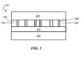
- FIG. 1 is an exemplary cross-sectional schematic illustration of an electrochemical cell comprising an ion conductor and a separator in the form of a composite structure, according to one set of embodiments.
- electrochemical cell 101 comprises first electrode 102 and second electrode 104.
- First electrode 102 (and/or second electrode 104) comprises an electroactive material.
- the electroactive material in first electrode 102 comprises lithium.
- First electrode 102 may be a negative electrode and second electrode 104 may be a positive electrode.
- electrochemical cell 101 comprise a separator 106 between first electrode 102 and second electrode 104.
- Separator 106 may comprise pores 108 in which electrolyte can reside.
- the separator and an ion conductor 112 form a composite structure, which may be bonded together and inhibit delamination or separation of the layers, as described herein.
- Ion conductor 112 can inhibit interaction of electrolyte with the electroactive material within electrode 102. In certain embodiments, ion conductor 112 substantially prevents interaction of electrolyte with the electroactive material within electrode 102.
- Inhibiting or preventing the interaction of electrolyte with the electroactive material within electrode 102 can reduce or eliminate the degree to which electrode 102 is degraded or otherwise rendered inoperable by the electrolyte.
- ion conductor 112 can function as a protective structure within the electrochemical cell.
- FIG. 1 shows an electrochemical cell
- the articles and methods described herein may encompass only components of electrochemical cells (e.g., a separator and an ion conductor without one of an anode and/or cathode).
- electrochemical cells e.g., a separator and an ion conductor without one of an anode and/or cathode.
- other components that are not shown in FIG. 1 may be included in electrochemical cells in some embodiments.
- an ion conductor layer e.g., an inorganic layer ion conductor layer
- At least two layers (e.g., two ion conductor layers) of the multi-layered structure may be formed of different materials, or the same material.
- at least one of the layers of the multilayered structure may comprise a lithium oxysulfide material, as described in more detail below. Other configurations are also possible.
- a free-standing, porous, separator layer may be used as the polymer matrix on which an ion conductor layer is deposited.
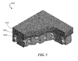
- a porous, separator layer 500 is provided, as illustrated in FIG. 2 .
- the porous separator layer may be conductive or non-conductive to ions.
- a suitable film is a commercially available porous, separator layer, such as those used in battery separators.
- the hole pathways through the layer can be quite tortuous in some embodiments. In certain embodiments, the hole pathways through the layer pass completely through the layer.
- This free standing layer can then be coated with an ion conductor (e.g., a ceramic such as a lithium oxysulfide).
- the approach of coating a free-standing separator with an ion conductor material offers a number of advantages over methods of fabricating other protective structures.
- First among these is the fact that the resulting structure does not have to be released from a carrier substrate. This not only results in a cost savings and a reduction of materials, but it avoids the possibility of damaging the fragile ion conductor coating during the release step.
- Second, binding the ion conductor material to the surface of the separator creates a mechanically stable platform for thin ion conductor (e.g., ceramic) coatings, greatly enhancing the coating's ability to withstand the mechanical stresses encountered when it is placed in a pressurized cell against a rough cathode.
- Third, such a process can be accomplished in a single chamber pump down. Not having to open the vacuum chamber during the deposition process reduces the chances for contamination as well as minimizes the handling of the material.
- an ion conductor material can be deposited onto a separator layer using a vacuum deposition process (e.g., sputtering, CVD, thermal or E-beam evaporation).
- Vacuum deposition can permit the deposition of smooth, dense, and homogenous thin layers.
- the pores of a separator layer 500 are substantially unfilled with an ion conductor 505 (e.g., ceramic).
- an ion conductor 505 e.g., ceramic
- those portions may be filled with an electrolyte solvent when positioned in an electrochemical cell.
- the ion conductor may be coated with a final layer of an electroactive material 510 (e.g., lithium).
- the electroactive material layer can be configured to adhere to the ion conductive layer, as described in more detail below. In certain embodiments of this process, there is no etching involved, which can make the process very fast and efficient.
- a protective structure includes multiple ion conductor layers (e.g., at least 2, 3, 4, 5, or 6 ion conductor layers) to form a multi-layered structure.
- an ion conductor layer e.g., an inorganic layer ion conductor layer
- at least two layers of the multi-layered structure are formed of the same material.
- At least one of the layers of the multi-layered structure may comprise a lithium oxysulfide material.
- the multi-layered structure may optionally include polymer layers (e.g., at least 1, 2, 3, 4, 5, or 6 polymer layers).
- the polymer layers are interspersed between two or more ion conductor layers.
- Each of the layers of the multi-layered structure may independently have features (e.g., thickness, conductivity, bulk electronic resistivity) described generally herein for the ion conductor layer and/or polymer layer.
- the ion conductor layer (which may comprise a lithium oxysulfide in some embodiments) may be in direct contact with each an electroactive material of a first electrode and the separator layer.
- the resulting ion conductor layer-separator composite can enhance the ion conductor layer's ability to withstand the mechanical stresses encountered when it is placed in a pressurized cell against a rough cathode.
- the surface of the separator layer may be treated (e.g., in a pre-treatment process) to enhance the surface energy of the separator layer.
- the increased surface energy of the separator layer can allow improved adhesion between the ion conductor layer and the separator compared to when the surface of the separator is not treated.
- adhesion is enhanced when a ratio of the thickness of the ion conductor layer to the average pore diameter of the separator is present in certain ranges, as described in more detail below.
- a variety of methods may be used.
- the method may involve, for example, a pre-treatment step in which the surface of the separator is treated prior to deposition of an ion conductor material.
- activation or a pre-treatment step involves subjecting the separator to a source of plasma.
- a source of plasma For example, an anode layer ion source (ALS) may be used to generate a plasma.
- an anode layer ion source involves generating electrons by an applied potential in the presence of a working gas.
- the resulting plasma generated creates additional ions and electrons, which accelerate towards the target substrate (e.g., the separator layer), providing ion bombardment of a substrate.
- This bombardment of the separator layer substrate increases the surface energy of the separator layer and promotes adhesion between the separator and the ion conductor material to follow.
- Various working gases can be used during a surface activation process such as plasma treatment.
- surface activation may occur in the presence of one or more gases including: air, oxygen, ozone, carbon dioxide, carbonyl sulfide, sulfur dioxide, nitrous oxide, nitric oxide, nitrogen dioxide, nitrogen, ammonia, hydrogen, freons (e.g., CF 4 , CF 2 Cl 2 , CF 3 Cl), silanes (e.g., SiH 4 , SiH 2 (CH 3 ) 2 , SiH 3 CH 3 ), and/or argon.
- gases including: air, oxygen, ozone, carbon dioxide, carbonyl sulfide, sulfur dioxide, nitrous oxide, nitric oxide, nitrogen dioxide, nitrogen, ammonia, hydrogen, freons (e.g., CF 4 , CF 2 Cl 2 , CF 3 Cl), silanes (e.g., SiH 4 , SiH 2 (CH 3 ) 2 , SiH 3 CH 3
- plasma treatment modifies the surface of the separator by ionizing the working gas and/or surface and, in some instances, forming or depositing activated functional chemical groups onto the surface.
- activation of certain functional groups on the surface of the separator layer may promote binding between the separator layer and an ion conductor material.
- the activated functional groups may include one or more of the following: carboxylates (e.g., -COOH), thiols (e.g., -SH), alcohols (e.g., -OH), acyls (e.g., -CO), sulfonics and/or sulfonic acids (e.g., -SOOH or -SO 3 H), amines (e.g., -NH 2 ), nitric oxides (e.g., -NO), nitrogen dioxides (e.g., -NO 2 ), chlorides (e.g., -Cl), haloalkyl groups (e.g., CF 3 ), silanes (e.g., SiH 3 ), and/or organosilanes (SiH 2 CH 3 ).
- Other functional groups are also possible.
- plasma treatment such as an ALS process
- a pressure ranging between, for example, 10 -2 to 10 -8 Torr.
- the pressure may be greater than or equal to 10 -8 Torr, greater than or equal to 10 -7 Torr, greater than or equal to 10 -6 Torr, greater than or equal to 10 -5 Torr, greater than or equal to 10 -4 Torr, or greater than or equal to 10 -3 Torr.
- the pressure may be less than or equal to 10 -2 Torr, less than or equal to 10 -3 Torr, less than or equal to 10 -4 Torr, less than or equal to 10 -5 Torr, or less than or equal to 10 -6 Torr. Combinations of the above-referenced ranges are also possible.
- Plasma treatment may generally be performed with a power of the ion source ranging between, for example, 5W to 200W.
- the power may be greater than or equal to 5 W, great than or equal to 10 W, greater than or equal to 20 W, greater than or equal to 50 W, greater than or equal to 100W, or greater than or equal to 200 W.
- the power may be less than or equal to 200 W, or less than or equal to 100W, or less than or equal to 50 W, or less than or equal to 20 W, or less than or equal to 5 W. Combinations of the above-referenced power ranges are also possible.
- the exposure time i.e., the time for which the separator layer is subjected to plasma treatment
- the exposure time may be greater than or equal to 1 second, greater than or equal to 10 seconds, greater than or equal to 30 seconds, greater than or equal to 1 minute, greater than or equal to 2 minutes, greater than or equal to 5 minutes, greater than or equal to 10 minutes, greater than or equal to 20 minutes, greater than or equal to 30 minutes, greater than or equal to 1 hour, or greater than or equal to 5 hours.
- the exposure time may be less than or equal to 10 hours, less than or equal to 1 hour, less than or equal to 30 minutes, less than or equal to 10 minutes, less than or equal to 5 minutes, less than or equal to 1 minute, less than or equal to 10 seconds, or less than or equal to 1 second. Combinations of the above-referenced exposure times are also possible.
- setup conditions can vary depending on the efficiency of the plasma system, the efficiency of the power supply, RF matching issues, gas distribution and selection, distance from target substrate, time of plasma exposure, etc.
- RF matching issues can vary depending on the efficiency of the plasma system, the efficiency of the power supply, RF matching issues, gas distribution and selection, distance from target substrate, time of plasma exposure, etc.
- various combinations of power at which the plasma source is operated, the operating pressure, gas selection, and the length of time of exposure to the plasma source are possible.
- plasma treatment is primarily described for increasing the surface energy of a substrate (e.g., a separator), other methods for increasing the surface energy of a substrate are also possible.
- flame surface treatment, corona treatment, chemical treatment, surface oxidation, absorption of functional groups to the surface, and/or surface grafting may be used to increase the surface energy of a substrate.
- the surface energy of the separator layer can be increased to any suitable value.
- the surface energy of the separator layer before treatment may be, for example, between 0 and 50 dynes.
- the surface energy may be at least 0 dynes, at least 10 dynes, at least 20 dynes, at least 30 dynes, at least 40 dynes, or at least 50 dynes.
- the surface energy may be less than 50 dynes, less than 40 dynes, less than 30 dynes, less than 20 dynes, or less than 10 dynes. Combinations of the above-referenced ranges are also possible.
- the surface energy after treatment may be, for example, less than 100 dynes, less than 90 dynes, less than 80 dynes, less than 70 dynes, less than 60 dynes, or less than 50 dynes. Combinations of the above-referenced ranges are also possible. Other surface energies are also possible.
- the surface energy of a separator surface before treatment can be increased at least 1.2 times, at least 1.5 times, at least 2 times, at least 3 times, at least 5 times, at least 10 times, at least 20 times, at least 50 times, at least 70 times, at least 100 times after treatment.
- the surface treatment may be increased up to 500 times after treatment. Other increases in surface energy are also possible.
- treatment of a surface results in chemical and/or physical bonds between an ion conductor and a separator layer being formed.
- the bonds may include covalent bonds.
- non-covalent interactions e.g., hydrophobic and/or hydrophilic interactions, electrostatic interactions, van der Waals interactions
- treatment e.g., pre-treatment
- treatment of a surface resulting in bond formation increases the degree of adhesion between two layers compared to the absence of such treatment.
- a tape test can be performed. Briefly, the tape test utilizes pressure-sensitive tape to qualitatively asses the adhesion between a first layer (e.g., a separator layer) and a second layer (e.g., a ion conducting layer).
- a first layer e.g., a separator layer
- a second layer e.g., a ion conducting layer
- an X-cut can be made through the first layer (e.g., separator layer) to the second layer (e.g., ion conducting layer).
- Pressure-sensitive tape can be applied over the cut area and removed. If the separator layer stays on the ion conducting layer (or vice versa), adhesion is good. If the separator layer comes off with the strip of tape, adhesion is poor.
- the tape test may be performed according to the standard ASTM D3359-02.
- a strength of adhesion between the separator and the inorganic ion conductor layer passes the tape test according to the standard ASTM D3359-02, meaning the ion conductor layer does not delaminate from the separator layer during the test.
- the tape test is performed after the two layers (e.g., a first layer such as a separator layer, to a second layer such as an ion conducting layer) have been included in a cell, such as a lithium-sulfur cell or any other appropriate cell described herein, that has been cycled at least 5 times, at least 10 times, at least 15 times, at least 20 times, at least 50 times, or at least 100 times, and the two layers pass the tape test after being removed from the cell (e.g., the first layer does not delaminate from the second layer during the test).
- a cell such as a lithium-sulfur cell or any other appropriate cell described herein
- the peel test may include measuring the adhesiveness or force required to remove a first layer (e.g., a separator layer) from a unit length of a second layer (e.g., a ion conducting layer), which can be measured in N/m, using a tensile testing apparatus or another suitable apparatus. Such experiments can optionally be performed in the presence of a solvent (e.g., an electrolyte) or other components to determine the influence of the solvent and/or components on adhesion.
- a solvent e.g., an electrolyte
- the strength of adhesion between two layers may be increased as a result of a treatment (e.g., pre-treatment) step described herein.
- the strength of adhesion after treatment may range, for example, between 100 N/m to 2000 N/m.
- the strength of adhesion may be at least 50 N/m, at least 100 N/m, at least 200 N/m, at least 350 N/m, at least 500 N/m, at least 700 N/m, at least 900 N/m, at least 1000 N/m, at least 1200 N/m, at least 1400 N/m, at least 1600 N/m, or at least 1800 N/m.
- the strength of adhesion may be less than or equal to 2000 N/m, less than or equal to 1500 N/m, less than or equal to 1000 N/m, less than or equal to 900 N/m, less than or equal to 700 N/m, less than or equal to 500 N/m, less than or equal to 350 N/m, less than or equal to 200 N/m, less than or equal to 100 N/m, or less than or equal to 50 N/m (see e.g. the thirteenth and the twenty-third preferred aspect of the present invention defined above).
- Other strengths of adhesion are also possible. The strength of adhesion may be measured according to standard.
- the relative thickness of the ion conductor layer to the average pore diameter of the separator layer may influence the degree of adhesive strength or bonding between the two layers in a composite. For instance, in some cases the thickness of the ion conductor layer may be greater than the average pore diameter (or largest pore diameter) of separator layer, which results in the formation of a smooth, dense, and homogenous ion conductor layer that resists delamination from separator layer.
- the ion conductor layer may serve as a solvent barrier which acts to prevent or reduce the likelihood of a liquid electrolyte from interacting with an electroactive material (e.g., lithium metal).
- an electroactive material e.g., lithium metal
- the ability of the composite ion conductor layer-separator to act as a barrier can be measured in part by an air permeation test (e.g., the Gurley Test).
- the Gurley Test determines the time required for a specific volume of air to flow through a standard area of the material. As such, larger air permeation times (Gurley-sec) generally correspond to better barrier properties.
- barrier properties e.g., higher air permeation times
- thinner layers may be more difficult for fluids to penetrate across the layer.
- the inventors observed that a reduced thickness of the ion conductor layer in an inorganic ion conductor layer-separator composite resulted in an improvement in barrier properties, as measured by an increase in air permeation time using the Gurley Test, compared to inorganic ion conductor layer-separator composites having relatively thicker inorganic ion conductor layers (see Example 3 and FIG. 5 ).
- the combination of a thin inorganic ion conductor layer and a plasma treated separator showed the highest air permeation time (and, therefore, enhanced barrier properties), compared to composites that did not include a plasma treated separator, or a composite that had a relatively thicker inorganic ion conductor layer.
- high permeation times, and therefore good barrier properties are contributed in part by good strength of adhesion between the two layers and good mechanical flexibility (i.e., lower film stresses) of the ion conductor layer so as to reduce the likelihood of cracking of the layer. Cracking of the ion conductor layer, similar to delamination between layers, typically results in poorer barrier properties.
- air permeation times of a composite described herein may be at least 1,000 Gurley-s, at least 5,000 Gurley-s, at least 10,000 Gurley-s, at least 20,000 Gurley-s, at least 40,000 Gurley-s, at least 60,000 Gurley-s, at least 80,000 Gurley-s, at least 100,000 Gurley-s, at least 120,000 Gurley-s, at least 140,000 Gurley-s, at least 160,000 Gurley-s, at least 180,000 Gurley-s, at least 200,000 Gurley-s, at least 500,000 Gurley-s, or at least 10 6 Gurley-s.
- the composite is substantially impermeable.
- the air permeation time may be less than or equal to 10 6 Gurley-s, less than or equal to 500,000 Gurley-s, less than or equal to 200,000 Gurley-s, less than or equal to 150,000 Gurley-s, less than or equal to 120,000 Gurley-s, less than or equal to 80,000 Gurley-s, less than or equal to 40,000 Gurley-s, less than or equal to 20,000 Gurley-s, less than or equal to 10,000 Gurley-s, or less than or equal to 5,000 Gurley-s.
- the air permeation times and Gurley tests described herein refer to those performed according to TAPPI Standard T 536 om-12, which involves a pressure differential of 3 kPa and a sample size of a square inch.
- an ion conductor or ion conductor layer described herein can be formed of a variety of types of materials.
- the material from which the ion conductor is formed may be selected to allow ions (e.g., electrochemically active ions, such as lithium ions) to pass through the ion conductor but to substantially impede electrons from passing across the ion conductor.
- ions e.g., electrochemically active ions, such as lithium ions
- substantially impedes in this context, it is meant that in this embodiment the material allows lithium ion flux at least ten times greater than electron passage.
- the material used for an ion conductor layer has a high enough conductivity (e.g., at least 10 -6 S/cm, or another conductivity value described herein) in its first amorphous state (see e.g. the first preferred aspect of the present invention defined above).
- the material may also be chosen for its ability to form a smooth, dense and homogenous thin films, especially on a polymer layer such as a separator. Lithium oxysulfides may especially include these characteristics (see e.g. the seventeenth preferred aspect of the present invention defined above).
- the ion conductor can be configured to be electronically non-conductive, in certain embodiments, which can inhibit the degree to which the ion conductor causes short circuiting of the electrochemical cell.
- all or part of the ion conductor can be formed of a material with a bulk electronic resistivity of at least about 10 4 Ohm-meters, at least about 10 5 Ohm-meters, at least about 10 10 Ohm-meters, at least about 10 15 Ohm-meters, or at least about 10 20 Ohm-meters.
- the bulk electronic resistivity may be, in some embodiments, less than or equal to about 10 20 Ohm-meters, or less than or equal to about 10 15 Ohm-meters (see e.g. the third preferred aspect of the present invention defined above). Combinations of the above-referenced ranges are also possible. Other values of bulk electronic resistivity are also possible.
- the average ionic conductivity (e.g., lithium ion conductivity) of the ion conductor material is at least about 10 -7 S/cm, at least about 10 -6 S/cm, at least about 10 -5 S/cm, at least about 10 -4 S/cm, at least about 10 -3 S/cm, at least about 10 -2 S/cm, at least about 10 -1 S/cm, at least about 1 S/cm, or at least about 10 S/cm.
- the average ionic conductivity may less than or equal to about 20 S/cm, less than or equal to about 10 S/cm, or less than or equal to 1 S/cm (see e.g. the eleventh and the twentieth preferred aspect of the present invention defined above). Conductivity may be measured at room temperature (e.g., 25 degrees Celsius).
- the ion conductor can be a solid. In some embodiments, the ion conductor comprises or may be substantially formed of a non-polymeric material. For example, the ion conductor may comprise or may be substantially formed of an inorganic material.
- the ion conductor layer is an inorganic ion conductive layer.
- the inorganic ion conductor layer may be a ceramic, a glass, or a glassy-ceramic.
- the ion conductor comprises an oxysulfide such as lithium oxysulfide.
- the lithium oxysulfide (or an ion conductor layer comprising a lithium oxysulfide) may have an oxide content between 0.1 - 20 wt%.
- the oxide content may be measured with respect to the total weight of the lithium oxysulfide material or the total weight of the ion conductor layer that comprises the lithium oxysulfide material.
- the oxide content may be at least 0.1 wt%, at least 1 wt%" at least 2 wt%, at least 5 wt%, at least 10 wt%, %, at least 15 wt%, or at least 20 wt%.
- the oxide content may be less than or equal to 20 wt%, less than or equal to 15 wt%, less than or equal to 10 wt%, less than or equal to 5 wt%, less than or equal to 2 wt%, or less than or equal to 1 wt% of the lithium oxysulfide (see e.g. the first preferred aspect of the present invention defined above). Combinations of the above-noted ranges are also possible.
- the elemental composition, including oxide content, of a layer may be determined by methods such as energy-dispersive X-ray spectroscopy.
- the lithium oxysulfide material in which an inorganic ion conductor material described herein comprises a lithium oxysulfide, has an atomic ratio of sulfur:oxygen of between, for example, 1:1 to 100:1.
- the atomic ratio between sulfur:oxygen in the lithium oxysulfide material (or an ion conductor layer comprising a lithium oxysulfide) may be at least 1:1, at least 2:1, at least 3:1, at least 5:1, at least 10:1, at least 20:1, at least 50:1, at least 70:1, or at least 90:1.
- the atomic ratio of sulfur:oxygen in the lithium oxysulfide material may be less than or equal to 100:1, less than or equal to 90:1, less than or equal to 70:1, less than or equal to 50:1, less than or equal to 20:1, less than or equal to 10:1, less than or equal to 5:1, less than or equal to 3:1, or less than or equal to 2:1 (see e.g. the first and the eighteenth preferred aspect of the present invention defined above). Combinations of the above-noted ranges are also possible. Other ranges are also possible.
- the elemental composition of a layer may be determined by methods such as energy-dispersive X-ray spectroscopy.
- x is at least 0.5, at least 1.0, at least 1.5, at least 2.0, or at least 2.5.
- x is less than or equal to 3.0, less than or equal to 2.5, less than or equal to 2.0, less than or equal to 1.5, less than or equal to 1.0, or less than or equal to 0.5 (see e.g. the sixth preferred aspect of the present invention defined above). Combinations of the above-noted ranges are also possible. Other values for x are also possible.
- the inorganic ion conductor such as a lithium oxysulfide described above, comprises a glass forming additive ranging from 0 wt% to 30 wt% of the inorganic ion conductor material.
- glass forming additives include, for example, SiO 2 , Li 2 SiO 3 , Li 4 SiO 4 , Li 3 PO 4 , LiPO 3 , Li 3 PS 4 , LiPS 3 , B 2 O 3 , B 2 S 3 .
- Other glass forming additives are also possible.
- glass forming additives may be at least 5 wt%, at least 10 wt%, at least 15 wt%, at least 20 wt%, at least 25 wt%, or at least 30 wt% of the inorganic ion conductor material. In certain embodiments, glass forming additives may be less than or equal to 30 wt%, less than or equal to 25 wt%, less than or equal to 20 wt%, less than or equal to 15 wt%, or less than or equal to 10 wt% of the inorganic ion conductor material (see e.g. the seventh preferred aspect of the present invention defined above). Combinations of the above-noted ranges are also possible. Other values of glass forming additives are also possible.
- one or more additional salts may be added to the inorganic ion conductor material at a range of, e.g., 0 to 50 mol%.
- additional salts are at least 0 mol%, at least 10 mol%, at least 20 mol%, at least 30 mol%, at least 40 mol%, or at least 50 mol%.
- additional salts are less than or equal to 50 mol%, less than or equal to 40 mol%, less than or equal to 30 mol%, less than or equal to 20 mol%, or less than or equal to 10 mol% (see e.g. the eighth preferred aspect of the present invention defined above). Combinations of the above-noted ranges are also possible. Other values of mol% are also possible.
- ion conductors include lithium nitrides, lithium silicates, lithium borates, lithium aluminates, lithium phosphates, lithium phosphorus oxynitrides, lithium silicosulfides, lithium germanosulfides, lithium oxides (e.g., Li 2 O, LiO, LiO 2 , LiRO 2 , where R is a rare earth metal), lithium lanthanum oxides, lithium titanium oxides, lithium borosulfides, lithium aluminosulfides, and lithium phosphosulfides, and combinations thereof.
- lithium nitrides lithium silicates, lithium borates, lithium aluminates, lithium phosphates, lithium phosphorus oxynitrides, lithium silicosulfides, lithium germanosulfides, lithium oxides (e.g., Li 2 O, LiO, LiO 2 , LiRO 2 , where R is a rare earth metal), lithium lanthanum oxides, lithium titanium oxides, lithium borosul
- the ion conductor is formed of a single-ion conductive material (e.g., a single-ion conductive ceramic material).
- the ion conductor material may be deposited by any suitable method such as sputtering, electron beam evaporation, vacuum thermal evaporation, laser ablation, chemical vapor deposition (CVD), thermal evaporation, plasma enhanced chemical vacuum deposition (PECVD), laser enhanced chemical vapor deposition, and jet vapor deposition.
- CVD chemical vapor deposition
- PECVD plasma enhanced chemical vacuum deposition
- jet vapor deposition The technique used may depend on the type of material being deposited, the thickness of the layer, etc.
- an ion conductor material can be deposited onto a separator using a vacuum deposition process (e.g., sputtering, CVD, thermal or E-beam evaporation).
- a vacuum deposition process e.g., sputtering, CVD, thermal or E-beam evaporation.
- Vacuum deposition can permit the deposition of smooth, dense, and homogenous thin layers.
- the thickness of the ion conductor layer may vary.
- the thickness of an ion conductor layer may vary over a range from, for example, 1 nm to 7 microns.
- the thickness of the ion conductor layer may be between 1-10 nm, between 10-100 nm, between 10-50 nm, between 30-70 nm, between 100-1000 nm, or between 1-7 microns.
- the thickness of an ion conductor layer may, for example, be less than or equal to 7 microns, less than or equal to 5 microns, less than or equal to 2 microns, less than or equal to 1000 nm, less than or equal to 600 nm, less than or equal to 500 nm, less than or equal to 250 nm, less than or equal to 100 nm, less than or equal to 70 nm, less than or equal to 50 nm, less than or equal to 25 nm, or less than or equal to 10 nm.
- an ion conductor layer is at least 10 nm thick, at least 20 nm thick, at least 30 nm thick, at least 100 nm thick, at least 400 nm thick, at least 1 micron thick, at least 2.5 microns thick, or at least 5 microns thick (see e.g. the tenth preferred aspect of the present invention defined above). Other thicknesses are also possible. Combinations of the above-noted ranges are also possible.
- the methods and articles provided herein may allow the formation of smooth surfaces.
- the RMS surface roughness of an ion conductor layer of a protective structure may be, for example, less than 1 ⁇ m.
- the RMS surface roughness for such surfaces may be, for example, between 0.5 nm and 1 ⁇ m (e.g., between 0.5 nm and 10 nm, between 10 nm and 50 nm, between 10 nm and 100 nm, between 50 nm and 200 nm, between 10 nm and 500 nm).
- the RMS surface roughness may be less than or equal to 0.9 ⁇ m, less than or equal to 0.8 ⁇ m, less than or equal to 0.7 ⁇ m, less than or equal to 0.6 ⁇ m, less than or equal to 0.5 ⁇ m, less than or equal to 0.4 ⁇ m, less than or equal to 0.3 ⁇ m, less than or equal to 0.2 ⁇ m, less than or equal to 0.1 ⁇ m, less than or equal to 75 nm, less than or equal to 50 nm, less than or equal to 25 nm, less than or equal to 10 nm, less than or equal to 5 nm, less than or equal to 2 nm, less than or equal to 1 nm.
- the RMS surface roughness may be greater than 1 nm, greater than 5 nm, greater than 10 nm, greater than 50 nm, greater than 100 nm, greater than 200 nm, greater than 500 nm, or greater than 700 nm. Other values are also possible. Combinations of the above-noted ranges are also possible (e.g., a RMS surface roughness of less than or equal to 0.5 ⁇ m and greater than 10 nm.
- a polymer layer of a protective structure may have a RMS surface roughness of one or more of the ranges noted above.
- the separator can be configured to inhibit (e.g., prevent) physical contact between a first electrode and a second electrode, which could result in short circuiting of the electrochemical cell.
- the separator can be configured to be substantially electronically non-conductive, which can inhibit the degree to which the separator causes short circuiting of the electrochemical cell.
- all or portions of the separator can be formed of a material with a bulk electronic resistivity of at least about 10 4 , at least about 10 5 , at least about 10 10 , at least about 10 15 , or at least about 10 20 Ohm-meters. Bulk electronic resistivity may be measured at room temperature (e.g., 25 degrees Celsius).
- the separator can be ionically conductive, while in other embodiments, the separator is substantially ionically non-conductive.
- the average ionic conductivity of the separator is at least about 10 -7 S/cm, at least about 10 -6 S/cm, at least about 10 -5 S/cm, at least about 10 -4 S/cm, at least about 10 -2 S/cm, at least about 10 -1 S/cm.
- the average ionic conductivity of the separator may be less than or equal to about 1 S/cm, less than or equal to about 10 -1 S/cm, less than or equal to about 10 -2 S/cm, less than or equal to about 10 -3 S/cm, less than or equal to about 10 -4 S/cm, less than or equal to about 10 -5 S/cm, less than or equal to about 10 -6 S/cm, less than or equal to about 10 -7 S/cm, or less than or equal to about 10 -8 S/cm. Combinations of the above-referenced ranges are also possible (e.g., an average ionic conductivity of at least about 10 -8 S/cm and less than or equal to about 10 -1 S/cm).
- the separator can be a solid.
- the separator may be porous to allow an electrolyte solvent to pass through it.
- the separator does not substantially include a solvent (like in a gel), except for solvent that may pass through or reside in the pores of the separator.
- a separator may be in the form of a gel.
- a separator may comprise a mixture of a polymeric binder, which may include one or more polymeric materials described herein (e.g., the polymers listed below for the separator), and a filler comprising a ceramic or a glassy/ceramic material, such as a material described herein for an ion conductor layer.
- a polymeric binder which may include one or more polymeric materials described herein (e.g., the polymers listed below for the separator)
- a filler comprising a ceramic or a glassy/ceramic material, such as a material described herein for an ion conductor layer.
- a separator as described herein can be made of a variety of materials.
- the separator may be polymeric in some instances, or formed of an inorganic material (e.g., glass fiber filter papers) in other instances.
- suitable separator materials include, but are not limited to, polyolefins (e.g., polyethylenes, poly(butene-1), poly(n-pentene-2), polypropylene, polytetrafluoroethylene), polyamines (e.g., poly(ethylene imine) and polypropylene imine (PPI)); polyamides (e.g., polyamide (Nylon), poly( ⁇ -caprolactam) (Nylon 6) , poly(hexamethylene adipamide) (Nylon 66)), polyimides (e.g., polyimide, polynitrile, and poly(pyromellitimide-1,4-diphenyl ether) (Kapton®) (NOMEX®) (KEVLAR®)); polyether ether ketone (
- the polymer may be selected from poly(n-pentene-2), polypropylene, polytetrafluoroethylene, polyamides (e.g., polyamide (Nylon), poly( ⁇ -caprolactam) (Nylon 6), poly(hexamethylene adipamide) (Nylon 66)), polyimides (e.g., polynitrile, and poly(pyromellitimide-1,4-diphenyl ether) (Kapton®) (NOMEX®) (KEVLAR®)), polyether ether ketone (PEEK), and combinations thereof (see e.g. the fourth preferred aspect of the present invention defined above).
- polyamides e.g., polyamide (Nylon), poly( ⁇ -caprolactam) (Nylon 6), poly(hexamethylene adipamide) (Nylon 66)
- polyimides e.g., polynitrile, and poly(pyromellitimide-1,4-diphenyl ether) (Kapton®) (
- the mechanical and electronic properties (e.g., conductivity, resistivity) of these polymers are known. Accordingly, those of ordinary skill in the art can choose suitable materials based on their mechanical and/or electronic properties (e.g., ionic and/or electronic conductivity/resistivity), and/or can modify such polymers to be ionically conducting (e.g., conductive towards single ions) based on knowledge in the art, in combination with the description herein.
- the polymer materials listed above and herein may further comprise salts, for example, lithium salts (e.g., LiSCN, LiBr, Lil, LiClO 4 , LiAsF 6 , LiSO 3 CF 3 , LiSO 3 CH 3 , LiBF 4 , LiB(Ph) 4 , LiPF 6 , LiC(SO 2 CF 3 ) 3 , and LiN(SO 2 CF 3 ) 2 ), to enhance ionic conductivity, if desired.
- lithium salts e.g., LiSCN, LiBr, Lil, LiClO 4 , LiAsF 6 , LiSO 3 CF 3 , LiSO 3 CH 3 , LiBF 4 , LiB(Ph) 4 , LiPF 6 , LiC(SO 2 CF 3 ) 3 , and LiN(SO 2 CF 3 ) 2
- LiSCN LiSCN, LiBr, Lil, LiClO 4 , LiAsF 6 , LiSO 3
- separators and separator materials suitable for use include those comprising a microporous xerogel layer, for example, a microporous pseudo-boehmite layer, which may be provided either as a free standing film or by a direct coating application on one of the electrodes, as described in U.S. Patent No. 6,153,337, filed December 19, 1997 and, entitled “Separators for electrochemical cells,” and U.S. Patent No. 6,306,545 filed December 17, 1998 and entitled “Separators for electrochemical cells.” Solid electrolytes and gel electrolytes may also function as a separator in addition to their electrolyte function.
- useful gel polymer electrolytes include, but are not limited to, those comprising one or more polymers selected from the group consisting of polyethylene oxides, polypropylene oxides, polyacrylonitriles, polysiloxanes, polyimides, polyphosphazenes, polyethers, sulfonated polyimides, perfluorinated membranes (NAFION resins), polydivinyl polyethylene glycols, polyethylene glycol diacrylates, polyethylene glycol dimethacrylates, derivatives of the foregoing, copolymers of the foregoing, crosslinked and network structures of the foregoing, and blends of the foregoing, and optionally, one or more plasticizers.
- polymers selected from the group consisting of polyethylene oxides, polypropylene oxides, polyacrylonitriles, polysiloxanes, polyimides, polyphosphazenes, polyethers, sulfonated polyimides, perfluorinated membranes (NAFION resins), polydivin
- separator materials include the separator materials described in U.S. Patent Publication No. 2010/0327811, filed July 1, 2010 and published December 30, 2010, entitled “Electrode Protection in Both Aqueous and Non-Aqueous Electromechanical Cells, Including Rechargeable Lithium Batteries,” which is incorporated herein by reference in its entirety for all purposes.
- the separator material can be selected based on its ability to survive ion conductor deposition processes without mechanically failing. For example, in embodiments in which relatively high temperatures or high pressures are used to form the ion conductor material (e.g., a ceramic ion conductor material), the separator material can be selected or configured to withstand such high temperatures and pressures.
- the ion conductor material e.g., a ceramic ion conductor material
- Those of ordinary skill in the art can employ a simple screening test to select an appropriate separator material from candidate materials.
- One simple screening test involves positioning a material as a separator in an electrochemical cell which, to function, requires passage of an ionic species across the material (e.g., through pores of the material) while maintaining electronic separation. If the material is substantially ionically conductive in this test, then electrical current will be generated upon discharging the electrochemical cell.
- Another simple screening test involves the ability to increase the surface energy of the separator by various methods described herein.
- a screening test may also involve testing the adhesion between the separator and an ion conductor layer as described herein.
- Another screening test may involve testing the ability of the separator to not swell in the presence of an electrolyte to be used in an electrochemical cell. Other simple tests can be conducted by those of ordinary skill in the art.
- the thickness of the separator may vary.
- the thickness of the separator may vary over a range from, for example, 5 microns to 40 microns.
- the thickness of the separator may be between 10-20 microns, between 20-30 microns, or between 20-40 microns.
- the thickness of the separator may be less than or equal to, e.g., 40 microns, less than or equal to 30 microns, less than or equal to 25 microns, less than or equal to 10 microns, or less than or equal to 9 microns.
- the separator is at least 9 microns thick, at least 10 microns thick, at least 20 microns thick, at least 25 microns thick, at least 30 microns thick, or at least 40 microns thick. Other thicknesses are also possible. Combinations of the above-noted ranges are also possible.
- a separator may have a smooth surface.
- the RMS surface roughness of a separator may be, for example, less than 1 ⁇ m.
- the RMS surface roughness for such surfaces may be, for example, between 0.5 nm and 1 ⁇ m (e.g., between 0.5 nm and 10 nm, between 10 nm and 50 nm, between 10 nm and 100 nm, between 50 nm and 200 nm, between 10 nm and 500 nm).
- the RMS surface roughness may be less than or equal to 0.9 ⁇ m, less than or equal to 0.8 ⁇ m, less than or equal to 0.7 ⁇ m, less than or equal to 0.6 ⁇ m, less than or equal to 0.5 ⁇ m, less than or equal to 0.4 ⁇ m, less than or equal to 0.3 ⁇ m, less than or equal to 0.2 ⁇ m, less than or equal to 0.1 ⁇ m, less than or equal to 75 nm, less than or equal to 50 nm, less than or equal to 25 nm, less than or equal to 10 nm, less than or equal to 5 nm, less than or equal to 2 nm, less than or equal to 1 nm.
- the RMS surface roughness may be greater than 1 nm, greater than 5 nm, greater than 10 nm, greater than 50 nm, greater than 100 nm, greater than 200 nm, greater than 500 nm, or greater than 700 nm. Other values are also possible. Combinations of the above-noted ranges are also possible (e.g., a RMS surface roughness of less than or equal to 0.5 ⁇ m and greater than 10 nm.
- the separator may be porous.
- the separator pore size may be, for example, less than 5 microns.
- the separator pore size may be between 50 nm and 5 microns, between 50 nm and 500 nm, between 100 nm and 300 nm, between 300 nm and 1 micron, between 500 nm and 5 microns.
- the pore size may be less than or equal to 5 microns, less than or equal to 1 micron, less than or equal to 500 nm, less than or equal to 300 nm, less than or equal to 100 nm, or less than or equal to 50 nm.
- the pore size may be greater than 50 nm, greater than 100 nm, greater than 300 nm, greater than 500 nm, or greater than 1 micron (see e.g. the ninth preferred aspect of the present invention defined above). Other values are also possible. Combinations of the above-noted ranges are also possible (e.g., a pore size of less than 300 nm and greater than 100 nm).
- the relative thickness of the ion conductor layer to the average pore diameter of the separator, which is positioned adjacent the ion conductor layer may influence the degree of adhesive strength of the two layers. For instance, the thickness of the ion conductor layer may be greater than the average pore diameter (or largest pore diameter) of separator.
- the average thickness of the ion conductor layer is at least 1.1 times, at least 1.2 times, at least 1.5 times, at least 1.7 times, at least 2 times, at least 2.5 times, at least 2.7 times, at least 2.8 times, at least 3.0 times, at least 3.2 times, at least 3.5 times, at least 3.8 times, at least 4.0 times, at least 5.0 times, at least 7.0 times, at least 10.0 times, or at least 20.0 times the average pore size (or the largest pore diameter) of the separator adjacent the ion conductor layer.
- the average thickness of the ion conductor layer may be less than or equal to 20.0 times, less than or equal to 10.0 times, less than or equal to 7.0 times, less than or equal to 5.0 times, less than or equal to 4.0 times, less than or equal to 3.8 times, less than or equal to 3.5 times, less than or equal to 3.2 times, less than or equal to 3.0 times, less than or equal to 2.8 times, less than or equal to 2.5 times, or less than or equal to 2 times the average pore size (or the largest pore diameter) of the separator adjacent the ion conductor layer.
- Other combinations of average pore diameter and ion conductor layer thicknesses are also possible.
- the ratio of thickness of the ion conductor layer to average pore diameter of the separator may be, for example, at least 1:1 (e.g., 1.1:1), at least 2:1, at least 3:2, at least 3:1, at least 4:1, at least 5:1, or at least 10:1.
- the ratio of thickness of the ion conductor layer to average pore diameter of the separator may be less than or equal to 10:1, less than or equal to 5:1, less than or equal to 3:1, less than or equal to 2:1 (e.g., 1.1:1), or less than or equal to 1:1 (see e.g. the twelfth preferred aspect of the present invention defined above). Other ratios are also possible. Combinations of the above-noted ranges are also possible.
- the thickness of the composite may vary over a range from, for example, 5 microns to 40 microns.
- the thickness of the composite may be between 10-20 microns, between 20-30 microns, or between 20-40 microns.
- the thickness of the composite may be, for example, less than or equal to 40 microns, less than or equal to 30 microns, less than or equal to 25 microns, less than or equal to 10 microns, less than or equal to 9 microns, or less than or equal to 7 microns.
- the composite is at least 5 microns thick, at least 7 microns thick, at least 9 microns thick, at least 10 microns thick, at least 20 microns thick, at least 25 microns thick, at least 30 microns thick, or at least 40 microns thick (see e.g. the twenty-first preferred aspect of the present invention defined above). Other thicknesses are also possible. Combinations of the above-noted ranges are also possible.
- the average ionic conductivity (e.g., lithium ion conductivity) of the composite is at least about 10 -7 S/cm, at least about 10 -6 S/cm, at least about 10 -5 S/cm, at least about 10 -4 S/cm, at least about 10 -2 S/cm, at least about 10 -1 S/cm, at least about 1 S/cm, at least about 10 S/cm.
- Conductivity may be measured at room temperature (e.g., 25 degrees Celsius).
- a composite structure described herein including an ion conductor layer and a separator may be a free-standing structure that may be packaged alone (optionally with suitable components such as a substrate for handling), together with an electroactive material to form a protected electrode, or assembled into an electrochemical cell (see e.g. the twenty-second preferred aspect of the present invention defined above).
- an electrochemical cell comprises a first electrode comprising an electroactive material, a second electrode and a composite positioned between the first and second electrodes.
- the composite comprises a separator comprising pores having an average pore size and an inorganic ion conductor layer bonded to the separator.
- the separator may have a bulk electronic resistivity of at least 10 4 Ohm meters (e.g., at least 10 10 Ohm meters, or at least 10 15 Ohm meters, e.g., between 10 10 Ohm meters to 10 15 Ohm meters).
- the inorganic ion conductor layer has a lithium-ion conductivity of at least at least 10 -6 S/cm, and comprises a lithium oxysulfide having an oxide content between 0.1 - 20 wt%.
- the ion conductor layer comprising the lithium oxysulfide may be a single layer in direct contact with each of the first electrode and the separator.
- the ion conductor layer is a part of a multi-layered structure comprising more than one ion conductor layers.
- at least two layers of the multi-layered structure are formed of different materials.
- at least two layers of the multi-layered structure are formed of the same material.
- the ion conductor layer comprises a glass forming additive ranging from 0 wt% to 30 wt% of the inorganic ion conductor material.
- the ion conductor layer may also optionally comprise one or more lithium salts, such as Lil, LiBr, LiCl, Li 2 CO 3 , or Li 2 SO 4 , although other salts described herein are also possible.
- the one or more lithium salts may be added to the inorganic ion conductor material at a range of, e.g., 0 to 50 mol%.
- the strength of adhesion between the separator and the inorganic ion conductor layer may be sufficiently strong to pass the tape test according to the standard ASTM D3359-02, in some instances.
- the strength of adhesion between the separator and the inorganic ion conductor layer may be, in some cases, at least 350 N/m or at least 500 N/m.
- the inorganic ion conductor layer is bonded to the separator by covalent bonding. Covalent bonding may be achieved by suitable methods described herein, and one embodiment, involves plasma treatment of the separator prior to addition or joining of the inorganic ion conductor layer and the separator.
- a ratio of a thickness of the inorganic ion conductor layer to the average pore size of the separator is at least 1.1:1 (e.g., at least 2:1, at least 3:1, or at least 5:1).
- the inorganic ion conductor layer may have a thickness of less than or equal to 2.0 microns (e.g., less than or equal to 1.5 microns, less than or equal to 1.3 microns, less than or equal to 1 micron, less than or equal to 800 nm, less than or equal to 600 nm, or between 400 nm and 600 nm).
- 2.0 microns e.g., less than or equal to 1.5 microns, less than or equal to 1.3 microns, less than or equal to 1 micron, less than or equal to 800 nm, less than or equal to 600 nm, or between 400 nm and 600 nm).
- a separator having a thickness between 5 microns and 40 microns is included.
- the separator may be a solid, polymeric separator.
- the separator may comprises or be formed of one or more of poly(n-pentene-2), polypropylene, polytetrafluoroethylene, a polyamide (e.g., polyamide (Nylon), poly( ⁇ -caprolactam) (Nylon 6), poly(hexamethylene adipamide) (Nylon 66)), a polyimide (e.g., polynitrile, and poly(pyromellitimide-1,4-diphenyl ether) (Kapton®) (NOMEX®) (KEVLAR®)), polyether ether ketone (PEEK), and combinations thereof.
- the separator may also comprise or be formed of other polymers or materials described herein.
- a separator may comprise a mixture of a polymeric binder and a filler comprising a ceramic or a glassy/ceramic material, such as a material described herein for an ion conductor layer.
- the separator may have an average pore size of less than or equal to 5 microns, less than or equal to 1 micron, less than or equal to 0.5 microns, between 0.05 - 5 microns, or between 0.1 - 0.3 microns.
- the composite may have an air permeation time of at least 20,000 Gurley-s, at least 40,000 Gurley-s, at least 60,000 Gurley-s, at least 80,000 Gurley-s, at least 100,000 Gurley-s, or at least 120,000 Gurley-s according to Gurley test TAPPI Standard T 536 om-12.
- the composite may have an air permeation time of less than or equal to 300,000 Gurley-s according to Gurley test TAPPI Standard T 536 om-12.
- the composite may be formed by, for example, depositing the ion conductor layer onto the separator by a vacuum deposition process such as electron beam evaporation or by a sputtering process (see e.g. the fifteenth preferred aspect of the present invention defined above).
- a first electrode may comprise lithium, such as lithium metal and/or a lithium alloy, as a first electroactive material
- a second electrode comprises sulfur as a second electroactive material (see e.g. the fourteenth preferred aspect of the present invention defined above).
- the electrochemical cell is a lithium-sulfur cell comprising a first electrode comprising lithium, a second electrode comprising sulfur, a separator arranged between said first electrode and said second electrode, and a solid ion conductor contacting and/or bonded to the separator, wherein said solid ion conductor comprises a lithium-ion conducting oxysulfide.
- a polymer layer is positioned on a substrate (e.g., an ion conductor layer), e.g., as part of a multi-layer protective structure, it should be appreciated that the polymer layer may be cured or otherwise prepared directly onto the substrate, or the polymer may be added separately to the substrate.
- the polymer layer can be a solid (e.g., as opposed to a gel).
- the polymer layer can be configured to be electronically non-conductive, in certain embodiments, and may be formed of a material with a bulk electronic resistivity of at least about 10 4 , at least about 10 5 , at least about 10 10 , at least about 10 15 , or at least about 10 20 Ohm-meters.
- the polymer can be ionically conductive.
- the average ionic conductivity of the polymer is at least about 10 -7 S/cm, at least about 10 -6 S/cm, at least about 10 -5 S/cm, at least about 10 -4 S/cm, at least about 10 -2 S/cm, at least about 10 -1 S/cm.
- the average ionic conductivity of the polymer may be less than or equal to about 1 S/cm, less than or equal to about 10 -1 S/cm, less than or equal to about 10 -2 S/cm, less than or equal to about 10 -3 S/cm, less than or equal to about 10 -4 S/cm, less than or equal to about 10 -5 S/cm, less than or equal to about 10 -6 S/cm, less than or equal to about 10 -7 S/cm, or less than or equal to about 10 -8 S/cm.
- an average ionic conductivity of at least about 10 -8 S/cm and less than or equal to about 10 -1 S/cm may be measured at room temperature (e.g., 25 degrees Celsius).
- a polymer layer described herein can be made of a variety of materials.
- materials that may be suitable for use in the polymer layer include, but are not limited to, polyamines (e.g., poly(ethylene imine) and polypropylene imine (PPI)); polyamides (e.g., polyamide (Nylon), poly( ⁇ -caprolactam) (Nylon 6) , poly(hexamethylene adipamide) (Nylon 66)), polyimides (e.g., polyimide, polynitrile, and poly(pyromellitimide-1,4-diphenyl ether) (Kapton)); vinyl polymers (e.g., polyacrylamide, poly(2-vinyl pyridine), poly(N-vinylpyrrolidone), poly(methylcyanoacrylate), poly(ethylcyanoacrylate), poly(butylcyanoacrylate), poly(isobutylcyanoacrylate), poly(vinyl acetate), poly (vinyl alcohol), poly(
- the polymer may be selected from the group consisting of polyvinyl alcohol, polyisobutylene, epoxy, polyethylene, polypropylene, polytetrafluoroethylene, and combinations thereof.
- the mechanical and electronic properties (e.g., conductivity, resistivity) of these polymers are known. Accordingly, those of ordinary skill in the art can choose suitable polymers based on their mechanical and/or electronic properties (e.g., ionic and/or electronic conductivity), and/or can modify such polymers to be ionically conducting (e.g., conductive towards single ions) based on knowledge in the art, in combination with the description herein.
- the polymer materials listed above may further comprise salts, for example, lithium salts (e.g., LiSCN, LiBr, Lil, LiClO 4 , LiAsF 6 , LiSO 3 CF 3 , LiSO 3 CH 3 , LiBF 4 , LiB(Ph) 4 , LiPF 6 , LiC(SO 2 CF 3 ) 3 , and LiN(SO 2 CF 3 ) 2 ), to enhance ionic conductivity.
- lithium salts e.g., LiSCN, LiBr, Lil, LiClO 4 , LiAsF 6 , LiSO 3 CF 3 , LiSO 3 CH 3 , LiBF 4 , LiB(Ph) 4 , LiPF 6 , LiC(SO 2 CF 3 ) 3 , and LiN(SO 2 CF 3 ) 2
- the ionic conductivity of the polymer material the ability to deposit or otherwise form the polymer material on or with other materials in the electrochemical cell
- the flexibility of the polymer material e.g., overall porosity, pore size distribution, and/or tortuosity
- the thickness of the polymer layer may vary.
- the thickness of the polymer layer may be less than or equal to, e.g., 40 microns, less than or equal to 30 microns, less than or equal to 25 microns, less than or equal to 10 microns, less than or equal to 5 microns, less than or equal to 3 microns, less than or equal to 2 microns, less than or equal to 1 micron, less than or equal to 0.5 microns, less than or equal to 0.1 microns, less than or equal to 0.05 microns.
- the polymer layer is at least 0.01 microns thick, at least 0.05 microns thick, at least 0.1 microns thick, at least 0.5 microns thick, at least 1 micron thick, at least 2 microns thick, at least 5 microns thick, at least 10 microns thick, at least 20 microns thick, at least 25 microns thick, at least 30 microns thick, or at least 40 microns thick.
- Other thicknesses are also possible. Combinations of the above-noted ranges are also possible.
- an electrode such as a first electrode (e.g., electrode 102 in FIGs. 1A and 1B ) comprises an electroactive material comprising lithium.
- Suitable electroactive materials comprising lithium include, but are not limited to, lithium metal (such as lithium foil and/or lithium deposited onto a conductive substrate) and lithium metal alloys (e.g., lithium-aluminum alloys and lithium-tin alloys).
- the electroactive lithium-containing material of an electrode comprises greater than 50 wt% lithium. In some cases, the electroactive lithium-containing material of an electrode comprises greater than 75 wt% lithium. In still other embodiments, the electroactive lithium-containing material of an electrode comprises greater than 90 wt% lithium.
- electroactive materials that can be used (e.g., in the first electrode, which can be a negative electrode) include, but are not limited to, other alkali metals (e.g., sodium, potassium, rubidium, caesium, francium), alkaline earth metals (e.g., beryllium, magnesium, calcium, strontium, barium, radium), and the like.
- the first electrode is an electrode for a lithium ion electrochemical cell. In some cases, the first electrode is an anode or negative electrode.
- the second electrode (e.g., electrode 102 in FIGs. 1A and 1B ) can comprise a variety of suitable electroactive materials. In some cases, the second electrode is a cathode or positive electrode.
- the electroactive material within an electrode can comprise metal oxides, such as LiCoO 2 , LiCo x Ni (1-x) O 2 , LiCo x Ni y Mn (1-x-y) (e.g., LiNi 1/3 Mn 1/3 Co 1/3 O 2 ), LiMn 2 O 4 , and combinations thereof.
- the electrode active material within an electrode e.g., within a positive electrode
- the electroactive material within an electrode can comprise electroactive transition metal chalcogenides, electroactive conductive polymers, and/or electroactive sulfur-containing materials, and combinations thereof.
- chalcogenides pertains to compounds that contain one or more of the elements of oxygen, sulfur, and selenium.
- suitable transition metal chalcogenides include, but are not limited to, the electroactive oxides, sulfides, and selenides of transition metals selected from the group consisting of Mn, V, Cr, Ti, Fe, Co, Ni, Cu, Y, Zr, Nb, Mo, Ru, Rh, Pd, Ag, Hf. Ta, W, Re, Os, and Ir.
- the transition metal chalcogenide is selected from the group consisting of the electroactive oxides of nickel, manganese, cobalt, and vanadium, and the electroactive sulfides of iron.
- an electrode e.g., a positive electrode
- suitable electroactive conductive polymers include, but are not limited to, electroactive and electronically conductive polymers selected from the group consisting of polypyrroles, polyanilines, polyphenylenes, polythiophenes, and polyacetylenes. In certain embodiments, it may be desirable to use polypyrroles, polyanilines, and/or polyacetylenes as conductive polymers.
- the electrode active material within an electrode can comprise sulfur.
- the electroactive material within an electrode can comprise electroactive sulfur-containing materials.
- Electroactive sulfur-containing materials refers to electrode active materials which comprise the element sulfur in any form, wherein the electrochemical activity involves the oxidation or reduction of sulfur atoms or moieties.
- the electroactive sulfur-containing material may comprise elemental sulfur (e.g., S 8 ).
- the electroactive sulfur-containing material comprises a mixture of elemental sulfur and a sulfur-containing polymer.
- suitable electroactive sulfur-containing materials may include, but are not limited to, elemental sulfur, sulfides or polysulfides (e.g., of alkali metals) which may be organic or inorganic, and organic materials comprising sulfur atoms and carbon atoms, which may or may not be polymeric.
- Suitable organic materials include, but are not limited to, those further comprising heteroatoms, conductive polymer segments, composites, and conductive polymers.
- an electroactive sulfur-containing material within an electrode e.g., a positive electrode
- the electroactive sulfur-containing material comprises at least about 50 wt%, at least about 75 wt%, or at least about 90 wt% sulfur.
- sulfur-containing polymers examples include those described in: U.S. Patent Nos. 5,601,947 and 5,690,702 to Skotheim et al. ; U.S. Patent Nos. 5,529,860 and 6,117,590 to Skotheim et al. ; U.S. Patent No. 6,201,100 issued Mar. 13, 2001, to Gorkovenko et al. , and PCT Publication No. WO 99/33130 .
- Other suitable electroactive sulfur-containing materials comprising polysulfide linkages are described in U.S. Patent No. 5,441,831 to Skotheim et al. ; U.S. Patent No. 4,664,991 to Perichaud et al. , and in U.S.
- Still further examples of electroactive sulfur-containing materials include those comprising disulfide groups as described, for example in, U.S. Patent No. 4,739,018 to Armand et al. ; U.S. Patent Nos. 4,833,048 and 4,917,974, both to De Jonghe et al. ; U.S. Patent Nos. 5,162,175 and 5,516,598, both to Visco et al. ; and U.S. Patent No. 5,324,599 to Oyama et al.
- the second electrode which can be, for example, a porous positive electrode
- sulfur is described as a component of an electroactive material within an electrode herein
- any suitable electroactive species may be used.
- the electroactive species within the second electrode e.g., a porous positive electrode
- a hydrogen-absorbing alloy such as those commonly used in nickel metal hydride batteries.
- the embodiments described herein may be used in association with any type of electro-chemical cell.
- the electrochemical cell is a primary (non-rechargeable) battery.
- the electrochemical cell may be a secondary (rechargeable) battery.
- Certain embodiments relate to lithium rechargeable batteries.
- the electrochemical cell comprises a lithium-sulfur rechargeable battery.
- lithium batteries are described herein, it is to be understood that any analogous alkali metal battery can be used.
- embodiments of the invention are particularly useful for protection of a lithium anode, the embodiments described herein may be applicable to other applications in which electrode protection is desired.
- electrolyte Any suitable electrolyte may be used in the electrochemical cells described herein. Generally, the choice of electrolyte will depend upon the chemistry of the electrochemical cell, and, in particular, the species of ion that is to be transported between electrodes in the electrochemical cell. Suitable electrolytes can comprise, in some embodiments, one or more ionic electrolyte salts to provide ionic conductivity and one or more liquid electrolyte solvents, gel polymer materials, or other polymer materials.
- non-aqueous liquid electrolyte solvents include, but are not limited to, non-aqueous organic solvents, such as, for example, N-methyl acetamide, acetonitrile, acetals, ketals, esters, carbonates, sulfones, sulfites, sulfolanes, aliphatic ethers, cyclic ethers, glymes, polyethers, phosphate esters, siloxanes, dioxolanes (e.g., 1,3-dioxolane), N-alkylpyrrolidones, bis(trifluoromethanesulfonyl)imide, substituted forms of the foregoing, and blends thereof.
- non-aqueous organic solvents such as, for example, N-methyl acetamide, acetonitrile, acetals, ketals, esters, carbonates, sulfones, sulfites, sulfolanes,
- aqueous solvents can be used as electrolytes for lithium cells.
- Aqueous solvents can include water, which can contain other components such as ionic salts.
- the electrolyte can include species such as lithium hydroxide, or other species rendering the electrolyte basic, so as to reduce the concentration of hydrogen ions in the electrolyte.
- the electrolyte can comprise one or more ionic electrolyte salts to provide ionic conductivity.
- one or more lithium salts e.g., LiSCN, LiBr, Lil, LiClO 4 , LiAsF 6 , LiSO 3 CF 3 , LiSO 3 CH 3 , LiBF 4 , LiB(Ph) 4 , LiPF 6 , LiC(SO 2 CF 3 ) 3 , and LiN(SO 2 CF 3 ) 2
- LiSCN, LiBr, Lil, LiClO 4 , LiAsF 6 , LiSO 3 CF 3 , LiSO 3 CH 3 , LiBF 4 , LiB(Ph) 4 , LiPF 6 , LiC(SO 2 CF 3 ) 3 , and LiN(SO 2 CF 3 ) 2 can be included.
- electrolyte salts that may be useful include lithium polysulfides (Li 2 S x ), and lithium salts of organic ionic polysulfides (LiS x R) n , where x is an integer from 1 to 20, n is an integer from 1 to 3, and R is an organic group, and those disclosed in U.S. Patent No. 5,538,812 to Lee et al.
- a range of concentrations of the ionic lithium salts in the solvent may be used such as from about 0.2 m to about 2.0 m (m is moles/kg of solvent). In some embodiments, a concentration in the range between about 0.5 m to about 1.5 m is used.
- ionic lithium salts to the solvent is optional in that upon discharge of Li/S cells the lithium sulfides or polysulfides formed typically provide ionic conductivity to the electrolyte, which may make the addition of ionic lithium salts unnecessary.
- electrochemical cells and components shown in is the figures are exemplary, and the orientation of the components can be varied. Additionally, non-planar arrangements, arrangements with proportions of materials different than those shown, and other alternative arrangements are useful in connection with certain embodiments of the present invention.
- a typical electrochemical cell could also include, for example, a containment structure, current collectors, external circuitry, and the like. Those of ordinary skill in the art are well aware of the many arrangements that can be utilized with the general schematic arrangement as shown in the figures and described herein.
- a layer when referred to as being "on”, “on top of”, or “adjacent” another layer, it can be directly on, on top of, or adjacent the layer, or an intervening layer may also be present.
- a layer that is “directly on”, “directly adjacent” or “in contact with” another layer means that no intervening layer is present.
- a layer that is positioned “between” two layers may be directly between the two layers such that no intervening layer is present, or an intervening layer may be present.
- This example describes a method for generating an ion conductor layer on a free-standing separator (e.g., an ion conductor-separator composite), with improved adhesive strength between the layers.
- a free-standing separator e.g., an ion conductor-separator composite
- the separator was pre-treated with plasma using an Anode Layer Ion Source in a chamber at a pressure of 10 -3 Torr, a power of 50 W, in the presence of argon gas. The treatment continued for 7 minutes.
- the surface energy of the separator was 32 dynes.
- the separator surface energy after plasma treatment was greater than 70 dynes, as measured by a dyne pen set.
- a layer of lithium oxysulfide, an ion conductor was deposited onto the separator to form an ion conductor layer by e-beam evaporation.
- the major components of the lithium oxysulfide layer were lithium, silicon, sulfur and oxygen, with the following ratios: 1.5:1 for Si:O, 4.5:1 for S:O, and 3.1:1 for S:Si.
- the thickness of the ion conductor layer ranged from about 600-800 nm, as shown in FIGs. 4A-4C .
- the ratio of thickness of the ion conductor layer to pore diameter of the separator in these experiments ranged from about 3:1 to 8:1.
- FIGS. 4A, 4B, and 4C are scanning electron microscopy (SEM) images showing the ion conductor (lithium oxysulfide) coating on the commercial separator.
- FIG. 4A is an SEM of the lithium oxysulfide coating on a 25-micron-thick separator. The thickness of the lithium oxysulfide layer was 610 nm.
- FIG. 4B is an SEM of a lithium oxysulfide layer on a 25 micron separator. The thickness of the lithium oxysulfide layer was 661 nm.
- FIG. 4C is an SEM cross-sectional image of an 800 nm thick lithium oxysulfide coating on the separator material. These images also show that the lithium oxysulfide material did not penetrate into the separator's pores.
- a tape test was performed according to standard ASTM-D3359-02 to determine adhesiveness between the ion conductor layer and the separator. The test demonstrated that the ion conductor was well bonded to the separator and did not delaminate from the separator.
- Example 1A An ion conductor-separator composite similar to that described in Example 1A was formed except the lithium oxysulfide ion conductor layer had a thickness of 1 micron. The surface of the separator was treated to plasma as described in Example 1A prior to deposition of the lithium oxysulfide layer.
- the final composite demonstrated 17 times reduced air permeation rates compared with an untreated separator (i.e., a separator that was not treated to plasma prior to deposition of the lithium oxysulfide layer, Comparative Example 1), as determined by a Gurley test performed with a pressure differential of 3 kPa (TAPPI Standard T 536 om-12).
- the final composite had an air permeation time of over 168 minutes, compared to about 9.7 minutes for the composite including the untreated separator (Comparative Example 1).
- the following is a comparative example describing an ion conductor layer that was poorly bonded to a separator.
- Example 1 The method described in Example 1 was used to form an ion conductor-separator composite, except here the separator was not treated with plasma prior to deposition of the ion conductor layer.
- the ion conductor-separator composite did not pass the tape test, demonstrating delamination of the ion conductor layer from the separator.
- the air permeation time was below 9.7 minutes as determined by a Gurley Test (TAPPI Standard T 536 om-12).
- This example shows the formation and performance of the ion conductor-separator composite of Example 1 in a lithium-sulfur electrochemical cell.
- the ion conductor (lithium oxysulfide)-coated separator of Example 1 was vacuum coated with metallic lithium (-25 microns of lithium deposited on top of the lithium oxysulfide layer). The lithium anode was protected with the lithium oxysulfide-coated separator and was assembled into a lithium-sulfur battery cell.
- the cathode contained 55% weight percent sulfur, 40% weight percent of carbon black and 5% weight percent of polyvinyl alcohol binder.
- the sulfur surface loading was approximately 2 mg/cm 2 .
- the active electrode covered a total surface area of 16.57 cm 2 .
- the lithium-sulfur battery cells were filled with an electrolyte containing 16% weight percent of lithium bis(Trifluoromethanesulfonyl)imide, 42% weight percent of dimethoxyethane, and 42% weight percent of 1,3-dioxolane solvents.
- the lithium-sulfur battery cells were discharged at 3 mA to 1.7 V and were charged at 3 mA. Charge was terminated when the lithium-sulfur battery cell reached 2.5 V or when charge time exceeded 15 hours if the cells were not able reaching 2.5 V.
- the lithium-sulfur battery cells were cycled over 30 times and showed the ability to reach 2.5 V at every cycle, demonstrating that the lithium oxysulfide layer performed well as a barrier, protecting lithium from the polysulfide shuttle.
- Multiple cells autopsied after 10 charge cycles showed no defects in the lithium oxysulfide layer and showed no evidence of lithium metal deposition on top of the lithium oxysulfide layer. All lithium was deposited under the lithium oxysulfide layer. Autopsies also showed that the ceramic and separator materials were well bonded after cycling.
- This example shows the formation and performance of the ion conductor-separator composite of Comparative Example 1 in a lithium-sulfur electrochemical cell.
- This example demonstrates the ability of ion conductor-separator composites (fabricated similarly to the method described in Example 1) to act as a barrier to fluids, as demonstrated by air permeation testing (Gurley test).
- Each of the samples included a 25 micron thick separator with pore diameters ranging between 0.1 micron to 0.5 microns, and a coating of lithium oxysulfide on top of the separator.
- Samples 1, 2, 3, and 6 included separators that were plasma treated before the addition of the lithium oxysulfide.
- Samples 4, 5, and 7 included separators that were untreated before the addition of the lithium oxysulfide layer.
- FIG. 5 is a graph showing air permeation time versus ion conductor layer thickness for composites including plasma treated and untreated separators. The figure highlights the improvement in air permeation times with plasma treatment of the separator before applying the lithium oxysulfide coating, i.e., samples 1, 2, 3, and 6, compared to composites that included separators that were untreated before the addition of the lithium oxysul-fide layer (samples 4, 5, and 7).
- a reference to "A and/or B,” when used in conjunction with open-ended language such as “comprising” can refer, in one embodiment, to A without B (optionally including elements other than B); in another embodiment, to B without A (optionally including elements other than A); in yet another embodiment, to both A and B (optionally including other elements); etc.
- the phrase "at least one,” in reference to a list of one or more elements, should be understood to mean at least one element selected from any one or more of the elements in the list of elements, but not necessarily including at least one of each and every element specifically listed within the list of elements and not excluding any combinations of elements in the list of elements.
- This definition also allows that elements may optionally be present other than the elements specifically identified within the list of elements to which the phrase "at least one" refers, whether related or unrelated to those elements specifically identified.
- At least one of A and B can refer, in one embodiment, to at least one, optionally including more than one, A, with no B present (and optionally including elements other than B); in another embodiment, to at least one, optionally including more than one, B, with no A present (and optionally including elements other than A); in yet another embodiment, to at least one, optionally including more than one, A, and at least one, optionally including more than one, B (and optionally including other elements); etc.
Landscapes
- Chemical & Material Sciences (AREA)
- Chemical Kinetics & Catalysis (AREA)
- Electrochemistry (AREA)
- General Chemical & Material Sciences (AREA)
- Inorganic Chemistry (AREA)
- Engineering & Computer Science (AREA)
- Materials Engineering (AREA)
- Cell Separators (AREA)
- Secondary Cells (AREA)
Applications Claiming Priority (1)
| Application Number | Priority Date | Filing Date | Title |
|---|---|---|---|
| US201461941546P | 2014-02-19 | 2014-02-19 |
Publications (2)
| Publication Number | Publication Date |
|---|---|
| EP2911221A1 true EP2911221A1 (fr) | 2015-08-26 |
| EP2911221B1 EP2911221B1 (fr) | 2025-04-23 |
Family
ID=52477654
Family Applications (1)
| Application Number | Title | Priority Date | Filing Date |
|---|---|---|---|
| EP15155510.9A Active EP2911221B1 (fr) | 2014-02-19 | 2015-02-18 | Protection d'électrode utilisant un composite comprenant un conducteur d'ions à inhibition d'électrolyte |
Country Status (1)
| Country | Link |
|---|---|
| EP (1) | EP2911221B1 (fr) |
Cited By (1)
| Publication number | Priority date | Publication date | Assignee | Title |
|---|---|---|---|---|
| US20230036332A1 (en) * | 2019-12-19 | 2023-02-02 | Lg Energy Solution, Ltd. | Membrane for electrochemical device, electrochemical device including membrane, and method for manufacturing electrochemical device |
Citations (22)
| Publication number | Priority date | Publication date | Assignee | Title |
|---|---|---|---|---|
| US4664991A (en) | 1984-09-21 | 1987-05-12 | Alain Perichaud | Composition based on a electron conducting polymer and its application to a positive active material for electrochemical generators |
| US4739018A (en) | 1983-09-20 | 1988-04-19 | Societe Nationale Elf Aquitaine | Polycarbon sulphide polymers |
| US4833048A (en) | 1988-03-31 | 1989-05-23 | The United States Of America As Represented By The United States Department Of Energy | Metal-sulfur type cell having improved positive electrode |
| US4917974A (en) | 1989-04-14 | 1990-04-17 | The United States Of America As Represented By The Department Of Energy | Lithium/organosulfur redox cell having protective solid electrolyte barrier formed on anode and method of making same |
| US5162175A (en) | 1989-10-13 | 1992-11-10 | Visco Steven J | Cell for making secondary batteries |
| US5324599A (en) | 1991-01-29 | 1994-06-28 | Matsushita Electric Industrial Co., Ltd. | Reversible electrode material |
| US5441831A (en) | 1992-12-17 | 1995-08-15 | Associated Universities, Inc. | Cells having cathodes containing polycarbon disulfide materials |
| US5516598A (en) | 1994-07-28 | 1996-05-14 | Polyplus Battery Company, Inc. | Secondary cell using organosulfur/metal charge transfer materials as positive electrode |
| US5529860A (en) | 1995-06-07 | 1996-06-25 | Moltech Corporation | Electroactive high storage capacity polyacetylene-co-polysulfur materials and electrolytic cells containing same |
| US5538812A (en) | 1994-02-04 | 1996-07-23 | Moltech Corporation | Electrolyte materials containing highly dissociated metal ion salts |
| US5601947A (en) | 1995-06-07 | 1997-02-11 | Moltech Corporation | Electroactive high storage capacity polycarbon-sulfide materials and electrolytic cells containing same |
| US5723230A (en) | 1995-02-27 | 1998-03-03 | Yazaki Corporation | Oligosulfide type electrode material and secondary battery containing such electrode material |
| US5783330A (en) | 1995-09-28 | 1998-07-21 | Yazaki Corporation | Electrode material and secondary battery |
| US5792575A (en) | 1995-09-11 | 1998-08-11 | Yazaki Corporation | Lithium sulfur secondary battery and elecrode material for a non-aqueous battery |
| US5882819A (en) | 1995-09-28 | 1999-03-16 | Yazaki Corporation | Sulfide-series electrode material and secondary battery with high energy density |
| WO1999033130A1 (fr) | 1997-12-19 | 1999-07-01 | Moltech Corporation | Polymeres organiques renfermant des polysulfures, stockant l'energie, hautement reticules, et electroactifs, destines a etre utilises dans des piles electrochimiques |
| US6117590A (en) | 1995-06-07 | 2000-09-12 | Moltech Corporation | Electroactive high storage capacity polyacetylene-co-polysulfur materials and electrolytic cells containing same |
| US6153337A (en) | 1997-12-19 | 2000-11-28 | Moltech Corporation | Separators for electrochemical cells |
| US20050095504A1 (en) * | 2003-10-31 | 2005-05-05 | Hee-Tak Kim | Negative electrode for lithium metal battery and lithium metal battery comprising the same |
| US20100327811A1 (en) | 2006-03-22 | 2010-12-30 | Sion Power Corporation | Electrode protection in both aqueous and non-aqueous electromechanical cells, including rechargeable lithium batteries |
| US20130266842A1 (en) * | 2010-06-17 | 2013-10-10 | Thomas Woehrle | Lithium Ion Cell |
| WO2015021373A1 (fr) * | 2013-08-08 | 2015-02-12 | Sion Power Corporation | Protection d'électrodes à auto-cicatrisation dans des cellules électrochimiques |
Family Cites Families (3)
| Publication number | Priority date | Publication date | Assignee | Title |
|---|---|---|---|---|
| US20020170169A1 (en) * | 2001-05-21 | 2002-11-21 | Gonzalez Jose E. | System and method for multilayer fabrication of lithium polymer batteries and cells using surface treated separators |
| US7070632B1 (en) * | 2001-07-25 | 2006-07-04 | Polyplus Battery Company | Electrochemical device separator structures with barrier layer on non-swelling membrane |
| JP5425107B2 (ja) * | 2008-03-05 | 2014-02-26 | イーグルピッチャー テクノロジーズ,エルエルシー | リチウム−硫黄電池およびそのカソード |
-
2015
- 2015-02-18 EP EP15155510.9A patent/EP2911221B1/fr active Active
Patent Citations (25)
| Publication number | Priority date | Publication date | Assignee | Title |
|---|---|---|---|---|
| US4739018A (en) | 1983-09-20 | 1988-04-19 | Societe Nationale Elf Aquitaine | Polycarbon sulphide polymers |
| US4664991A (en) | 1984-09-21 | 1987-05-12 | Alain Perichaud | Composition based on a electron conducting polymer and its application to a positive active material for electrochemical generators |
| US4833048A (en) | 1988-03-31 | 1989-05-23 | The United States Of America As Represented By The United States Department Of Energy | Metal-sulfur type cell having improved positive electrode |
| US4917974A (en) | 1989-04-14 | 1990-04-17 | The United States Of America As Represented By The Department Of Energy | Lithium/organosulfur redox cell having protective solid electrolyte barrier formed on anode and method of making same |
| US5162175A (en) | 1989-10-13 | 1992-11-10 | Visco Steven J | Cell for making secondary batteries |
| US5324599A (en) | 1991-01-29 | 1994-06-28 | Matsushita Electric Industrial Co., Ltd. | Reversible electrode material |
| US5441831A (en) | 1992-12-17 | 1995-08-15 | Associated Universities, Inc. | Cells having cathodes containing polycarbon disulfide materials |
| US5538812A (en) | 1994-02-04 | 1996-07-23 | Moltech Corporation | Electrolyte materials containing highly dissociated metal ion salts |
| US5516598A (en) | 1994-07-28 | 1996-05-14 | Polyplus Battery Company, Inc. | Secondary cell using organosulfur/metal charge transfer materials as positive electrode |
| US5723230A (en) | 1995-02-27 | 1998-03-03 | Yazaki Corporation | Oligosulfide type electrode material and secondary battery containing such electrode material |
| US6117590A (en) | 1995-06-07 | 2000-09-12 | Moltech Corporation | Electroactive high storage capacity polyacetylene-co-polysulfur materials and electrolytic cells containing same |
| US5690702A (en) | 1995-06-07 | 1997-11-25 | Moltech Corporation | Method of making electroactive high storage capacity polycarbon-sulfide materials and electrolytic cells containing same |
| US5529860A (en) | 1995-06-07 | 1996-06-25 | Moltech Corporation | Electroactive high storage capacity polyacetylene-co-polysulfur materials and electrolytic cells containing same |
| US5601947A (en) | 1995-06-07 | 1997-02-11 | Moltech Corporation | Electroactive high storage capacity polycarbon-sulfide materials and electrolytic cells containing same |
| US5792575A (en) | 1995-09-11 | 1998-08-11 | Yazaki Corporation | Lithium sulfur secondary battery and elecrode material for a non-aqueous battery |
| US5783330A (en) | 1995-09-28 | 1998-07-21 | Yazaki Corporation | Electrode material and secondary battery |
| US5882819A (en) | 1995-09-28 | 1999-03-16 | Yazaki Corporation | Sulfide-series electrode material and secondary battery with high energy density |
| WO1999033130A1 (fr) | 1997-12-19 | 1999-07-01 | Moltech Corporation | Polymeres organiques renfermant des polysulfures, stockant l'energie, hautement reticules, et electroactifs, destines a etre utilises dans des piles electrochimiques |
| US6153337A (en) | 1997-12-19 | 2000-11-28 | Moltech Corporation | Separators for electrochemical cells |
| US6201100B1 (en) | 1997-12-19 | 2001-03-13 | Moltech Corporation | Electroactive, energy-storing, highly crosslinked, polysulfide-containing organic polymers and methods for making same |
| US6306545B1 (en) | 1997-12-19 | 2001-10-23 | Moltech Corporation | Separators for electrochemical cells |
| US20050095504A1 (en) * | 2003-10-31 | 2005-05-05 | Hee-Tak Kim | Negative electrode for lithium metal battery and lithium metal battery comprising the same |
| US20100327811A1 (en) | 2006-03-22 | 2010-12-30 | Sion Power Corporation | Electrode protection in both aqueous and non-aqueous electromechanical cells, including rechargeable lithium batteries |
| US20130266842A1 (en) * | 2010-06-17 | 2013-10-10 | Thomas Woehrle | Lithium Ion Cell |
| WO2015021373A1 (fr) * | 2013-08-08 | 2015-02-12 | Sion Power Corporation | Protection d'électrodes à auto-cicatrisation dans des cellules électrochimiques |
Non-Patent Citations (1)
| Title |
|---|
| "United States Patent Office Manual of Patent Examining Procedures" |
Cited By (1)
| Publication number | Priority date | Publication date | Assignee | Title |
|---|---|---|---|---|
| US20230036332A1 (en) * | 2019-12-19 | 2023-02-02 | Lg Energy Solution, Ltd. | Membrane for electrochemical device, electrochemical device including membrane, and method for manufacturing electrochemical device |
Also Published As
| Publication number | Publication date |
|---|---|
| EP2911221B1 (fr) | 2025-04-23 |
Similar Documents
| Publication | Publication Date | Title |
|---|---|---|
| US20220278354A1 (en) | Electrode protection using a composite comprising an electrolyte-inhibiting ion conductor | |
| US11710847B2 (en) | Electrode protection using electrolyte-inhibiting ion conductor | |
| EP3108533B1 (fr) | Protection d'électrode au moyen d'un électrolyte conducteur d'ions | |
| US11742477B2 (en) | Protective layers for electrodes and electrochemical cells | |
| JP6770952B2 (ja) | リチウムイオン電気化学電池における保護層、並びに関連する電極および方法 | |
| CN103227344B (zh) | 包括可再充电锂电池的含水和非水电化学电池中的电极保护 | |
| KR20200042962A (ko) | 전기 화학 전지용 보호 막 | |
| KR20150132319A (ko) | 보호된 전극 구조물 및 방법 | |
| KR20150132427A (ko) | 보호된 전극 구조물 | |
| TW201820678A (zh) | 具有介電塗層之電池隔板 | |
| EP3246968B1 (fr) | Couches protectrices pour électrodes et cellules électrochimiques | |
| EP2911221B1 (fr) | Protection d'électrode utilisant un composite comprenant un conducteur d'ions à inhibition d'électrolyte |
Legal Events
| Date | Code | Title | Description |
|---|---|---|---|
| PUAI | Public reference made under article 153(3) epc to a published international application that has entered the european phase |
Free format text: ORIGINAL CODE: 0009012 |
|
| AK | Designated contracting states |
Kind code of ref document: A1 Designated state(s): AL AT BE BG CH CY CZ DE DK EE ES FI FR GB GR HR HU IE IS IT LI LT LU LV MC MK MT NL NO PL PT RO RS SE SI SK SM TR |
|
| AX | Request for extension of the european patent |
Extension state: BA ME |
|
| 17P | Request for examination filed |
Effective date: 20160226 |
|
| RBV | Designated contracting states (corrected) |
Designated state(s): AL AT BE BG CH CY CZ DE DK EE ES FI FR GB GR HR HU IE IS IT LI LT LU LV MC MK MT NL NO PL PT RO RS SE SI SK SM TR |
|
| STAA | Information on the status of an ep patent application or granted ep patent |
Free format text: STATUS: EXAMINATION IS IN PROGRESS |
|
| 17Q | First examination report despatched |
Effective date: 20170613 |
|
| RAP1 | Party data changed (applicant data changed or rights of an application transferred) |
Owner name: SION POWER CORPORATION |
|
| REG | Reference to a national code |
Ref country code: DE Ref legal event code: R079 Free format text: PREVIOUS MAIN CLASS: H01M0002160000 Ipc: H01M0008041190 Ref country code: DE Ref legal event code: R079 Ref document number: 602015091484 Country of ref document: DE Free format text: PREVIOUS MAIN CLASS: H01M0002160000 Ipc: H01M0008041190 |
|
| GRAP | Despatch of communication of intention to grant a patent |
Free format text: ORIGINAL CODE: EPIDOSNIGR1 |
|
| STAA | Information on the status of an ep patent application or granted ep patent |
Free format text: STATUS: GRANT OF PATENT IS INTENDED |
|
| RIC1 | Information provided on ipc code assigned before grant |
Ipc: H01M 10/052 20100101ALN20241023BHEP Ipc: H01M 50/491 20210101ALN20241023BHEP Ipc: H01M 4/58 20100101ALI20241023BHEP Ipc: H01M 50/497 20210101ALI20241023BHEP Ipc: H01M 50/489 20210101ALI20241023BHEP Ipc: H01M 50/414 20210101ALI20241023BHEP Ipc: H01M 50/46 20210101ALI20241023BHEP Ipc: H01M 4/38 20060101ALI20241023BHEP Ipc: H01M 8/04119 20160101AFI20241023BHEP |
|
| INTG | Intention to grant announced |
Effective date: 20241121 |
|
| GRAS | Grant fee paid |
Free format text: ORIGINAL CODE: EPIDOSNIGR3 |
|
| GRAA | (expected) grant |
Free format text: ORIGINAL CODE: 0009210 |
|
| STAA | Information on the status of an ep patent application or granted ep patent |
Free format text: STATUS: THE PATENT HAS BEEN GRANTED |
|
| P01 | Opt-out of the competence of the unified patent court (upc) registered |
Free format text: CASE NUMBER: APP_11345/2025 Effective date: 20250307 |
|
| AK | Designated contracting states |
Kind code of ref document: B1 Designated state(s): AL AT BE BG CH CY CZ DE DK EE ES FI FR GB GR HR HU IE IS IT LI LT LU LV MC MK MT NL NO PL PT RO RS SE SI SK SM TR |
|
| REG | Reference to a national code |
Ref country code: GB Ref legal event code: FG4D |
|
| REG | Reference to a national code |
Ref country code: CH Ref legal event code: EP |
|
| REG | Reference to a national code |
Ref country code: DE Ref legal event code: R096 Ref document number: 602015091484 Country of ref document: DE |
|
| REG | Reference to a national code |
Ref country code: IE Ref legal event code: FG4D |
|
| REG | Reference to a national code |
Ref country code: NL Ref legal event code: MP Effective date: 20250423 |
|
| PG25 | Lapsed in a contracting state [announced via postgrant information from national office to epo] |
Ref country code: NL Free format text: LAPSE BECAUSE OF FAILURE TO SUBMIT A TRANSLATION OF THE DESCRIPTION OR TO PAY THE FEE WITHIN THE PRESCRIBED TIME-LIMIT Effective date: 20250423 |
|
| REG | Reference to a national code |
Ref country code: AT Ref legal event code: MK05 Ref document number: 1788696 Country of ref document: AT Kind code of ref document: T Effective date: 20250423 |
|
| PG25 | Lapsed in a contracting state [announced via postgrant information from national office to epo] |
Ref country code: PT Free format text: LAPSE BECAUSE OF FAILURE TO SUBMIT A TRANSLATION OF THE DESCRIPTION OR TO PAY THE FEE WITHIN THE PRESCRIBED TIME-LIMIT Effective date: 20250825 Ref country code: ES Free format text: LAPSE BECAUSE OF FAILURE TO SUBMIT A TRANSLATION OF THE DESCRIPTION OR TO PAY THE FEE WITHIN THE PRESCRIBED TIME-LIMIT Effective date: 20250423 Ref country code: FI Free format text: LAPSE BECAUSE OF FAILURE TO SUBMIT A TRANSLATION OF THE DESCRIPTION OR TO PAY THE FEE WITHIN THE PRESCRIBED TIME-LIMIT Effective date: 20250423 |
|
| REG | Reference to a national code |
Ref country code: LT Ref legal event code: MG9D |
|
| PG25 | Lapsed in a contracting state [announced via postgrant information from national office to epo] |
Ref country code: GR Free format text: LAPSE BECAUSE OF FAILURE TO SUBMIT A TRANSLATION OF THE DESCRIPTION OR TO PAY THE FEE WITHIN THE PRESCRIBED TIME-LIMIT Effective date: 20250724 Ref country code: NO Free format text: LAPSE BECAUSE OF FAILURE TO SUBMIT A TRANSLATION OF THE DESCRIPTION OR TO PAY THE FEE WITHIN THE PRESCRIBED TIME-LIMIT Effective date: 20250723 |
|
| PG25 | Lapsed in a contracting state [announced via postgrant information from national office to epo] |
Ref country code: PL Free format text: LAPSE BECAUSE OF FAILURE TO SUBMIT A TRANSLATION OF THE DESCRIPTION OR TO PAY THE FEE WITHIN THE PRESCRIBED TIME-LIMIT Effective date: 20250423 |
|
| PG25 | Lapsed in a contracting state [announced via postgrant information from national office to epo] |
Ref country code: BG Free format text: LAPSE BECAUSE OF FAILURE TO SUBMIT A TRANSLATION OF THE DESCRIPTION OR TO PAY THE FEE WITHIN THE PRESCRIBED TIME-LIMIT Effective date: 20250423 |
|
| PG25 | Lapsed in a contracting state [announced via postgrant information from national office to epo] |
Ref country code: HR Free format text: LAPSE BECAUSE OF FAILURE TO SUBMIT A TRANSLATION OF THE DESCRIPTION OR TO PAY THE FEE WITHIN THE PRESCRIBED TIME-LIMIT Effective date: 20250423 |
|
| PG25 | Lapsed in a contracting state [announced via postgrant information from national office to epo] |
Ref country code: AT Free format text: LAPSE BECAUSE OF FAILURE TO SUBMIT A TRANSLATION OF THE DESCRIPTION OR TO PAY THE FEE WITHIN THE PRESCRIBED TIME-LIMIT Effective date: 20250423 |
|
| PG25 | Lapsed in a contracting state [announced via postgrant information from national office to epo] |
Ref country code: RS Free format text: LAPSE BECAUSE OF FAILURE TO SUBMIT A TRANSLATION OF THE DESCRIPTION OR TO PAY THE FEE WITHIN THE PRESCRIBED TIME-LIMIT Effective date: 20250723 |
|
| PG25 | Lapsed in a contracting state [announced via postgrant information from national office to epo] |
Ref country code: IS Free format text: LAPSE BECAUSE OF FAILURE TO SUBMIT A TRANSLATION OF THE DESCRIPTION OR TO PAY THE FEE WITHIN THE PRESCRIBED TIME-LIMIT Effective date: 20250823 |
|
| PG25 | Lapsed in a contracting state [announced via postgrant information from national office to epo] |
Ref country code: LV Free format text: LAPSE BECAUSE OF FAILURE TO SUBMIT A TRANSLATION OF THE DESCRIPTION OR TO PAY THE FEE WITHIN THE PRESCRIBED TIME-LIMIT Effective date: 20250423 |
|
| PG25 | Lapsed in a contracting state [announced via postgrant information from national office to epo] |
Ref country code: SM Free format text: LAPSE BECAUSE OF FAILURE TO SUBMIT A TRANSLATION OF THE DESCRIPTION OR TO PAY THE FEE WITHIN THE PRESCRIBED TIME-LIMIT Effective date: 20250423 Ref country code: DK Free format text: LAPSE BECAUSE OF FAILURE TO SUBMIT A TRANSLATION OF THE DESCRIPTION OR TO PAY THE FEE WITHIN THE PRESCRIBED TIME-LIMIT Effective date: 20250423 |
|
| PG25 | Lapsed in a contracting state [announced via postgrant information from national office to epo] |
Ref country code: CZ Free format text: LAPSE BECAUSE OF FAILURE TO SUBMIT A TRANSLATION OF THE DESCRIPTION OR TO PAY THE FEE WITHIN THE PRESCRIBED TIME-LIMIT Effective date: 20250423 |
|
| PG25 | Lapsed in a contracting state [announced via postgrant information from national office to epo] |
Ref country code: EE Free format text: LAPSE BECAUSE OF FAILURE TO SUBMIT A TRANSLATION OF THE DESCRIPTION OR TO PAY THE FEE WITHIN THE PRESCRIBED TIME-LIMIT Effective date: 20250423 |
|
| REG | Reference to a national code |
Ref country code: DE Ref legal event code: R097 Ref document number: 602015091484 Country of ref document: DE |
|
| PG25 | Lapsed in a contracting state [announced via postgrant information from national office to epo] |
Ref country code: RO Free format text: LAPSE BECAUSE OF FAILURE TO SUBMIT A TRANSLATION OF THE DESCRIPTION OR TO PAY THE FEE WITHIN THE PRESCRIBED TIME-LIMIT Effective date: 20250423 Ref country code: SK Free format text: LAPSE BECAUSE OF FAILURE TO SUBMIT A TRANSLATION OF THE DESCRIPTION OR TO PAY THE FEE WITHIN THE PRESCRIBED TIME-LIMIT Effective date: 20250423 |
|
| PG25 | Lapsed in a contracting state [announced via postgrant information from national office to epo] |
Ref country code: IT Free format text: LAPSE BECAUSE OF FAILURE TO SUBMIT A TRANSLATION OF THE DESCRIPTION OR TO PAY THE FEE WITHIN THE PRESCRIBED TIME-LIMIT Effective date: 20250423 |
|
| PLBE | No opposition filed within time limit |
Free format text: ORIGINAL CODE: 0009261 |
|
| STAA | Information on the status of an ep patent application or granted ep patent |
Free format text: STATUS: NO OPPOSITION FILED WITHIN TIME LIMIT |
|
| REG | Reference to a national code |
Ref country code: CH Ref legal event code: L10 Free format text: ST27 STATUS EVENT CODE: U-0-0-L10-L00 (AS PROVIDED BY THE NATIONAL OFFICE) Effective date: 20260304 |
|
| 26N | No opposition filed |
Effective date: 20260126 |