EP2911245B1 - Reflektorantennenvorrichtung - Google Patents
Reflektorantennenvorrichtung Download PDFInfo
- Publication number
- EP2911245B1 EP2911245B1 EP13846682.6A EP13846682A EP2911245B1 EP 2911245 B1 EP2911245 B1 EP 2911245B1 EP 13846682 A EP13846682 A EP 13846682A EP 2911245 B1 EP2911245 B1 EP 2911245B1
- Authority
- EP
- European Patent Office
- Prior art keywords
- reflector
- shape
- subreflector
- antenna device
- main reflector
- Prior art date
- Legal status (The legal status is an assumption and is not a legal conclusion. Google has not performed a legal analysis and makes no representation as to the accuracy of the status listed.)
- Active
Links
Images





Classifications
-
- H—ELECTRICITY
- H01—ELECTRIC ELEMENTS
- H01Q—ANTENNAS, i.e. RADIO AERIALS
- H01Q19/00—Combinations of primary active antenna elements and units with secondary devices, e.g. with quasi-optical devices, for giving the antenna a desired directional characteristic
- H01Q19/10—Combinations of primary active antenna elements and units with secondary devices, e.g. with quasi-optical devices, for giving the antenna a desired directional characteristic using reflecting surfaces
- H01Q19/18—Combinations of primary active antenna elements and units with secondary devices, e.g. with quasi-optical devices, for giving the antenna a desired directional characteristic using reflecting surfaces having two or more spaced reflecting surfaces
- H01Q19/19—Combinations of primary active antenna elements and units with secondary devices, e.g. with quasi-optical devices, for giving the antenna a desired directional characteristic using reflecting surfaces having two or more spaced reflecting surfaces comprising one main concave reflecting surface associated with an auxiliary reflecting surface
- H01Q19/192—Combinations of primary active antenna elements and units with secondary devices, e.g. with quasi-optical devices, for giving the antenna a desired directional characteristic using reflecting surfaces having two or more spaced reflecting surfaces comprising one main concave reflecting surface associated with an auxiliary reflecting surface with dual offset reflectors
-
- H—ELECTRICITY
- H01—ELECTRIC ELEMENTS
- H01Q—ANTENNAS, i.e. RADIO AERIALS
- H01Q19/00—Combinations of primary active antenna elements and units with secondary devices, e.g. with quasi-optical devices, for giving the antenna a desired directional characteristic
- H01Q19/10—Combinations of primary active antenna elements and units with secondary devices, e.g. with quasi-optical devices, for giving the antenna a desired directional characteristic using reflecting surfaces
- H01Q19/12—Combinations of primary active antenna elements and units with secondary devices, e.g. with quasi-optical devices, for giving the antenna a desired directional characteristic using reflecting surfaces wherein the surfaces are concave
- H01Q19/17—Combinations of primary active antenna elements and units with secondary devices, e.g. with quasi-optical devices, for giving the antenna a desired directional characteristic using reflecting surfaces wherein the surfaces are concave the primary radiating source comprising two or more radiating elements
-
- H—ELECTRICITY
- H01—ELECTRIC ELEMENTS
- H01Q—ANTENNAS, i.e. RADIO AERIALS
- H01Q19/00—Combinations of primary active antenna elements and units with secondary devices, e.g. with quasi-optical devices, for giving the antenna a desired directional characteristic
- H01Q19/10—Combinations of primary active antenna elements and units with secondary devices, e.g. with quasi-optical devices, for giving the antenna a desired directional characteristic using reflecting surfaces
- H01Q19/18—Combinations of primary active antenna elements and units with secondary devices, e.g. with quasi-optical devices, for giving the antenna a desired directional characteristic using reflecting surfaces having two or more spaced reflecting surfaces
- H01Q19/19—Combinations of primary active antenna elements and units with secondary devices, e.g. with quasi-optical devices, for giving the antenna a desired directional characteristic using reflecting surfaces having two or more spaced reflecting surfaces comprising one main concave reflecting surface associated with an auxiliary reflecting surface
- H01Q19/191—Combinations of primary active antenna elements and units with secondary devices, e.g. with quasi-optical devices, for giving the antenna a desired directional characteristic using reflecting surfaces having two or more spaced reflecting surfaces comprising one main concave reflecting surface associated with an auxiliary reflecting surface wherein the primary active element uses one or more deflecting surfaces, e.g. beam waveguide feeds
-
- H—ELECTRICITY
- H01—ELECTRIC ELEMENTS
- H01Q—ANTENNAS, i.e. RADIO AERIALS
- H01Q1/00—Details of, or arrangements associated with, antennas
- H01Q1/27—Adaptation for use in or on movable bodies
- H01Q1/28—Adaptation for use in or on aircraft, missiles, satellites, or balloons
- H01Q1/288—Satellite antennas
Definitions
- the present invention relates to a reflector antenna device used for, for example, satellite communications.
- a reflector antenna whose aperture shape, in which asperities are formed on a mirror surface, is a circular shape is generally used in order to make it possible to transmit and receive a beam according to a requested service area.
- a main reflector having such a rectangular aperture shape is disclosed by, for example, the following nonpatent reference 1.
- Nonpatent reference 2 describes a low-cost, lightweight, low wind load, transparent antenna for direct broadcast satellite TV reception.
- the antenna comprises dual parabolic cylindrical reflectors.
- Nonpatent reference 3 describes a Gregorian antenna with a main reflector and a subreflector for a C-band or Ku-band spacecraft antenna. Both the main and the subreflectors are shaped to cover square and rectangular service areas.
- Patent reference 1 describes a multiple beam array antenna that is designed with an aperture shape which conforms to the particular coverage area to which the antenna is directed.
- the antenna consists of individual horn antennas that are nested together to form the array.
- Patent reference 2 describes an antenna which is provided with a non-circular major reflecting mirror in which the electric field is distributed in a non-circular aperture shape and which radiates a radio wave in space or receives a radio wave from space and with a primary radiator feeding power to the non-circular major reflecting mirror.
- Patent reference 3 describes an antenna which is orientable, directional and capable of use as a transmit and/or receive antenna. It includes at least one reflector, at least one source of electromagnetic radiation including means for exciting the source with two orthogonal linear polarizations and a mechanical system for positioning and holding the source and the reflector.
- Patent reference 4 describes a low-cost, lightweight, low wind load, broadband, foldable / deployable base station antenna which uses dual parabolic cylindrical reflectors.
- Patent reference 5 describes a Mersenne reflector system using parabolic troughs as primary and secondary reflectors, in Cassegrainian and Gregorian configurations.
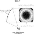
- the conventional reflector antenna device is constructed as above, even if a main reflector having a rectangular aperture shape is used, the shape of the beam radiated from the primary radiator onto the main reflector is a circular shape (refer to Fig. 9 ). Therefore, in the main reflector having a rectangular shape, the radiation level of a peripheral part (in the example of Fig. 9 , a part close to each of the four corners of the aperture shape) which is enlarged from the circular shape decreases, and the degree of freedom of reflector shaping cannot be improved sufficiently.
- a problem is that as the radiation level of the peripheral part is increased conversely, the loss of spillover from a portion (in the example of Fig. 9 , a portion close to the center of the aperture shape) which is not enlarged from the circular shape increases, and the efficiency degrades.
- the present invention is made in order to solve the above-mentioned problems, and it is therefore an object of the present invention to provide a reflector antenna device that can improve the degree of freedom of reflector shaping without causing reduction in efficiency.
- a reflector antenna device including: a main reflector that has a rectangular aperture shape; a primary radiator that is configured to radiate a beam having an amplitude distribution with a circular shape; and a subreflector.
- the subreflector has a mirror surface on which asperities are formed, to convert the shape of the amplitude distribution of the beam radiated by said primary radiator from said circular shape to a rectangular shape similar to the aperture shape of said main reflector, and is configured to reflect the beam and radiate the beam having said amplitude distribution with said rectangular shape onto said main reflector.
- the reflector antenna device in accordance with the present invention is configured in such a way as to include: the main reflector that has a rectangular aperture shape; the primary radiator that radiates a circle-shaped beam; and the subreflector that converts the shape of the beam radiated by the primary radiator from the circular shape to a rectangular shape similar to the aperture shape of the main reflector and reflects the beam, and that radiates the beam having the rectangular shape onto the main reflector, there is provided an advantage of being able to improve the degree of freedom of reflector shaping without causing reduction in efficiency.
- Fig. 1 is a structural diagram showing a reflector antenna device in accordance with Embodiment 1.
- Embodiment 1 is not an embodiment of the present invention but helpful for understanding certain aspects thereof.
- Fig. 1 a cross section of the reflector antenna device, an aperture shape at the time when a main reflector 1 is viewed from the front, and a distribution of the amplitude of a beam radiated onto the aperture of the main reflector 1 are described.
- asperities are formed on the mirror surface of the main reflector 1 in order to form a beam, and the main reflector 1 has a rectangular aperture shape 2.
- a primary radiator 3 is a source of radio wave radiation that radiates a beam having a rectangular shape similar to the aperture shape 2 of the main reflector 1 onto the main reflector 1.
- the primary radiator 3 constructs a beam radiator.
- the amplitude distribution 4 is the amplitude distribution of the beam radiated onto the main reflector 1 by the primary radiator 3.
- the beam having a rectangular shape emitted from the primary radiator 3 is reflected by the main reflector 1, and the beam having the rectangular shape reflected by the main reflector 1 is radiated in a determined direction (a direction of a requested service area).
- the amplitude distribution of the beam radiated onto the main reflector 1 turns into the one like the amplitude distribution 4 shown in Fig. 1 .
- the amplitude distribution on the main reflector decreases to less than the amplitude distribution 4 shown in Fig. 1 at a point close to any one of the four corners of the aperture shape. Therefore, in the whole region of the aperture shape, a difference occurs in the energy.
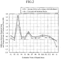
- Fig. 2 is an explanatory drawing showing an example of comparison of evaluation points of the shaped beam of the reflector antenna device in accordance with Embodiment 1 with those of the conventional reflector antenna device.
- P1 to P12 and R1 in the horizontal axis of Fig. 2 denote evaluation points at each of which a gain is evaluated, and 11 denotes an evaluation point at which isolation is evaluated.
- Fig. 2 shows the difference between a required gain or a required isolation value, and its designed value at each of the evaluation points, and the reflector antenna device increases in performance as this value approaches zero.
- the reflector antenna device in accordance with this Embodiment 1 increases in gain by 0.2dB or more at each of the evaluation points P1 to P12 and R1, and also increases in isolation by about 1dB at the evaluation point I1, as compared with the conventional reflector antenna device.
- the radiation of a beam having a shape similar to the aperture shape of the main reflector improves the degree of freedom of the determination of the asperities of the main reflector for forming the shaped beam, i.e., the degree of forming in the reflector shaping.
- the reflector antenna device in accordance with this Embodiment 1 is configured in such a way as to include the main reflector 1 that has a rectangular aperture shape 2, and the primary radiator 3 that radiates a beam having a rectangular shape similar to the aperture shape 2 of the main reflector 1 onto the main reflector 1, there is provided an advantage of being able to improve the degree of freedom of reflector shaping without causing reduction in efficiency.
- Fig. 3 is a structural diagram showing a reflector antenna device in accordance with Embodiment 2.
- Embodiment 2 is not an embodiment of the present invention but helpful for understanding certain aspects thereof.
- the same reference numerals as those shown in Fig. 1 denote the same components or like components, the explanation of the components will be omitted hereafter.
- a multimode horn antenna 5 is a horn antenna in which a plurality of waveguide modes are combined (for example, a fundamental mode and a plurality of higher modes of a waveguide are combined), and is a primary radiator that is configured in such a way as to radiate a beam having a rectangular shape.
- the multimode horn antenna 5 constructs a beam radiator.
- this Embodiment 2 is an embodiment in which the multimode horn antenna 5 is used as the primary radiator, a beam having a rectangular shape similar to the aperture shape 2 of a main reflector 1 can be radiated onto the main reflector 1 also in the case in which the multimode horn antenna 5 is used as the primary radiator, like in the case of above-mentioned Embodiment 1. Therefore, there is provided an advantage of being able to improve the degree of freedom of reflector shaping without causing reduction in efficiency.
- Fig. 4 is a structural diagram showing a reflector antenna device in accordance with Embodiment 3.
- Embodiment 3 is not an embodiment of the present invention but helpful for understanding certain aspects thereof.
- the same reference numerals as those shown in Fig. 1 denote the same components or like components, the explanation of the components will be omitted hereafter.
- An active phased array antenna 6 is a primary radiator that includes an amplifier and a phase shifter for each antenna element, and is configured in such a way as to radiate a beam having a rectangular shape by properly adjusting the amplification amount of each amplifier and the phase amount of each phase shifter to optimize each excitation coefficient of the primary radiator.
- the active phased array antenna 6 constructs a beam radiator.
- this Embodiment 3 is an embodiment in which the active phased array antenna 6 is used as the primary radiator, a beam having a rectangular shape similar to the aperture shape 2 of a main reflector 1 can be radiated onto the main reflector 1 also in the case in which the active phased array antenna 6 is used as the primary radiator, like in the case of above-mentioned Embodiment 1. Therefore, there is provided an advantage of being able to improve the degree of freedom of reflector shaping without causing reduction in efficiency.
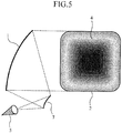
- Fig. 5 is a structural diagram showing a reflector antenna device in accordance with Embodiment 4.
- Embodiment 4 is not an embodiment of the present invention but helpful for understanding certain aspects thereof.
- the same reference numerals as those shown in Fig. 3 denote the same components or like components, the explanation of the components will be omitted hereafter.
- a subreflector 7 is a Cassegrain-type reflector which has a rectangular aperture shape and whose mirror surface is a hyperboloid of revolution.
- a beam radiator is comprised of a multimode horn antenna 5 and the subreflector 7.
- a beam having a rectangular shape emitted from the multimode horn antenna 5 is radiated directly onto the main reflector 1
- a beam having a rectangular shape emitted from the multimode horn antenna 5 can be reflected by the subreflector 7 having a rectangular aperture shape, and the beam having the rectangular shape reflected by the subreflector 7 can be radiated onto the main reflector 1.
- the same advantage as that provided by above-mentioned Embodiment 2 can be provided.
- Fig. 6 is a structural diagram showing a reflector antenna device in accordance with Embodiment 5.
- Embodiment 5 is not an embodiment of the present invention but helpful for understanding certain aspects thereof.
- the same reference numerals as those shown in Fig. 3 denote the same components or like components, the explanation of the components will be omitted hereafter.
- a subreflector 8 is a Gregorian-type reflector which has a rectangular aperture shape and whose mirror surface is an ellipsoid of revolution.
- a beam radiator is comprised of a multimode horn antenna 5 and the subreflector 8.
- a beam having a rectangular shape emitted from the multimode horn antenna 5 is radiated directly onto the main reflector 1
- a beam having a rectangular shape emitted from the multimode horn antenna 5 can be reflected by the subreflector 8 having a rectangular aperture shape, and the beam having the rectangular shape reflected by the subreflector 8 can be radiated onto the main reflector 1.
- the same advantage as that provided by above-mentioned Embodiment 2 can be provided.
- Fig. 7 is a structural diagram showing a reflector antenna device in accordance with Embodiment 6 of the present invention.
- the same reference numerals as those shown in Fig. 5 denote the same components or like components, the explanation of the components will be omitted hereafter.
- a primary radiator 9 is a source of radio wave radiation that radiates a circle-shaped beam.
- a subreflector 10 has a mirror surface on which asperities are formed in order to form a beam, and has a rectangular aperture shape.
- the mirror surface of the subreflector 10 is shaped in such a way as to, when reflecting the beam radiated by the primary radiator 9, convert the shape of the beam from the circular shape to a rectangular shape, and the beam having the rectangular shape is radiated onto a main reflector 1.
- the subreflector 10 is a Cassegrain-type reflector whose mirror surface before the formation of asperities is a hyperboloid of revolution, and the asperities are formed by using, for example, a non-linear optimization method in such a way that a beam having a rectangular shape can be acquired.
- a beam radiator is comprised of the primary radiator 9 and the subreflector 10.
- a beam having a rectangular shape emitted from the multimode horn antenna 5 is reflected by the subreflector 7 having a rectangular aperture shape, and the beam having the rectangular shape reflected by the subreflector 7 is radiated onto the main reflector 1 is shown in above-mentioned Embodiment 4, a beam having a circular shape emitted from the primary radiator 9 can be reflected by the subreflector 10 having a rectangular aperture shape and the shape of the beam can be converted from the circular shape to a rectangular shape when reflected, so that the beam having the rectangular shape is radiated onto the main reflector 1.
- Fig. 8 is a structural diagram showing a reflector antenna device in accordance with Embodiment 7 of the present invention.
- the same reference numerals as those shown in Fig. 7 denote the same components or like components, the explanation of the components will be omitted hereafter.
- a subreflector 11 has a mirror surface on which asperities are formed in order to form a beam, and has a rectangular aperture shape.
- the mirror surface of the subreflector 11 is shaped in such a way as to, when reflecting the beam radiated by the primary radiator 9, convert the shape of the beam from the circular shape to a rectangular shape, and the beam having the rectangular shape is radiated onto a main reflector 1.
- the subreflector 11 is a Gregorian-type reflector whose mirror surface before the formation of asperities is an ellipsoid of revolution, and the asperities are formed by using, for example, a non-linear optimization method in such a way that a beam having a rectangular shape can be acquired.
- a beam radiator is comprised of the primary radiator 9 and the subreflector 11.
- a beam having a rectangular shape emitted from the multimode horn antenna 5 is reflected by the subreflector 7 having a rectangular aperture shape, and the beam having the rectangular shape reflected by the subreflector 7 is radiated onto the main reflector 1 is shown in above-mentioned Embodiment 4, a beam having a circular shape emitted from the primary radiator 9 can be reflected by the subreflector 11 having a rectangular aperture shape and the shape of the beam can be converted from the circular shape to a rectangular shape when reflected, so that the beam having the rectangular shape is radiated onto the main reflector 1.
- the reflector antenna device in accordance with the present invention includes the main reflector that has a rectangular aperture shape, and the beam radiator that radiates a beam having a rectangular shape similar to the aperture shape of the main reflector onto the main reflector, and can improve the degree of freedom of reflector shaping without causing reduction in efficiency, the reflector antenna device is suitable for use in satellite communications and so on.
Landscapes
- Aerials With Secondary Devices (AREA)
Claims (3)
- Reflektorantenne, umfassend:einen Hauptreflektor (1), der eine rechteckige Öffnungsform (2) aufweist;einen Primärradiator (9), der eingerichtet ist, einen Strahl, aufweisend eine Amplitudenverteilung mit einer Kreisform, abzustrahlen; undeinen Nebenreflektor (10; 11);dadurch gekennzeichnet, dass der Nebenreflektor (10; 11) eine Spiegeloberfläche aufweist, auf der Unebenheiten ausgebildet sind, um die Form der Amplitudenverteilung des durch den Primärradiator (9) abgestrahlten Strahls in eine rechteckige Form ähnlich der Öffnungsform des Hauptreflektors (1) umzuwandeln, und eingerichtet ist, den Strahl zu reflektieren und den Strahl, aufweisend die Amplitudenverteilung mit der rechteckigen Form, auf den Hauptreflektor (1) abzustrahlen.
- Reflektorantenneneinrichtung nach Anspruch 1, wobei der Nebenreflektor (10) ein Nebenreflektor vom Cassegrain-Typ ist.
- Reflektorantenne nach Anspruch 1, wobei der Nebenreflektor (11) ein Nebenreflektor vom Gregory-Typ ist.
Applications Claiming Priority (2)
| Application Number | Priority Date | Filing Date | Title |
|---|---|---|---|
| JP2012228862 | 2012-10-16 | ||
| PCT/JP2013/058996 WO2014061293A1 (ja) | 2012-10-16 | 2013-03-27 | 反射鏡アンテナ装置 |
Publications (3)
| Publication Number | Publication Date |
|---|---|
| EP2911245A1 EP2911245A1 (de) | 2015-08-26 |
| EP2911245A4 EP2911245A4 (de) | 2016-06-01 |
| EP2911245B1 true EP2911245B1 (de) | 2020-10-28 |
Family
ID=50487872
Family Applications (1)
| Application Number | Title | Priority Date | Filing Date |
|---|---|---|---|
| EP13846682.6A Active EP2911245B1 (de) | 2012-10-16 | 2013-03-27 | Reflektorantennenvorrichtung |
Country Status (4)
| Country | Link |
|---|---|
| US (1) | US9543659B2 (de) |
| EP (1) | EP2911245B1 (de) |
| JP (1) | JPWO2014061293A1 (de) |
| WO (1) | WO2014061293A1 (de) |
Families Citing this family (1)
| Publication number | Priority date | Publication date | Assignee | Title |
|---|---|---|---|---|
| JP6327962B2 (ja) * | 2014-06-06 | 2018-05-23 | 三菱電機株式会社 | 反射鏡アンテナ装置 |
Citations (3)
| Publication number | Priority date | Publication date | Assignee | Title |
|---|---|---|---|---|
| US5796370A (en) * | 1993-12-02 | 1998-08-18 | Alcatel Espace | Orientable antenna with conservation of polarization axes |
| US20100091396A1 (en) * | 2008-10-10 | 2010-04-15 | Sunflower Daylighting | Afocal Optical Concentrator |
| WO2011160649A2 (en) * | 2010-06-24 | 2011-12-29 | Mohamed Saed Abdelazez Sanad Elgendy | A low wind load lightweight foldable / deployable base station antenna for mobile tv, wimax, cdma and gsm |
Family Cites Families (9)
| Publication number | Priority date | Publication date | Assignee | Title |
|---|---|---|---|---|
| JPS5698905A (en) * | 1980-01-11 | 1981-08-08 | Kokusai Denshin Denwa Co Ltd <Kdd> | Dual reflecting mirror antenna |
| JP2572799B2 (ja) | 1988-02-29 | 1997-01-16 | 日本放送協会 | 鏡面修正複反射鏡アンテナ |
| JP3005229B2 (ja) | 1989-05-31 | 2000-01-31 | 日本電気株式会社 | 鏡面修整アンテナ |
| US5175562A (en) | 1989-06-23 | 1992-12-29 | Northeastern University | High aperture-efficient, wide-angle scanning offset reflector antenna |
| US5113197A (en) * | 1989-12-28 | 1992-05-12 | Space Systems/Loral, Inc. | Conformal aperture feed array for a multiple beam antenna |
| JP3860241B2 (ja) | 1996-02-05 | 2006-12-20 | 忠 高野 | 開口面アンテナ |
| JPH10229308A (ja) | 1997-02-13 | 1998-08-25 | Mitsubishi Electric Corp | ビーム走査アンテナ装置 |
| FR2793073B1 (fr) | 1999-04-30 | 2003-04-11 | France Telecom | Antenne a reflecteur continu pour reception multiple de faisceaux de satellite |
| JP3816408B2 (ja) | 2002-02-15 | 2006-08-30 | 三菱電機株式会社 | マルチモードホーンアンテナ |
-
2013
- 2013-03-27 EP EP13846682.6A patent/EP2911245B1/de active Active
- 2013-03-27 JP JP2014541960A patent/JPWO2014061293A1/ja active Pending
- 2013-03-27 WO PCT/JP2013/058996 patent/WO2014061293A1/ja not_active Ceased
- 2013-03-27 US US14/416,793 patent/US9543659B2/en active Active
Patent Citations (3)
| Publication number | Priority date | Publication date | Assignee | Title |
|---|---|---|---|---|
| US5796370A (en) * | 1993-12-02 | 1998-08-18 | Alcatel Espace | Orientable antenna with conservation of polarization axes |
| US20100091396A1 (en) * | 2008-10-10 | 2010-04-15 | Sunflower Daylighting | Afocal Optical Concentrator |
| WO2011160649A2 (en) * | 2010-06-24 | 2011-12-29 | Mohamed Saed Abdelazez Sanad Elgendy | A low wind load lightweight foldable / deployable base station antenna for mobile tv, wimax, cdma and gsm |
Non-Patent Citations (1)
| Title |
|---|
| H.-H. VISKUM ET AL: "Coverage flexibility by means of a reconformable subreflector", ANTENNAS AND PROPAGATION SOCIETY INTERNATIONAL SYMPOSIUM, 1997. IEEE., 1997 DIGEST MONTREAL, QUE., CANADA 13-18 JULY 1997, vol. 2, 1 January 1997 (1997-01-01), US, pages 1378 - 1381, XP055695057, ISBN: 978-0-7803-4178-4, DOI: 10.1109/APS.1997.631835 * |
Also Published As
| Publication number | Publication date |
|---|---|
| EP2911245A4 (de) | 2016-06-01 |
| JPWO2014061293A1 (ja) | 2016-09-05 |
| US20150207237A1 (en) | 2015-07-23 |
| US9543659B2 (en) | 2017-01-10 |
| WO2014061293A1 (ja) | 2014-04-24 |
| EP2911245A1 (de) | 2015-08-26 |
Similar Documents
| Publication | Publication Date | Title |
|---|---|---|
| JP3584925B2 (ja) | 宇宙太陽光発電システム | |
| US9281561B2 (en) | Multi-band antenna system for satellite communications | |
| US6320553B1 (en) | Multiple frequency reflector antenna with multiple feeds | |
| US7034771B2 (en) | Multi-beam and multi-band antenna system for communication satellites | |
| EP1152484A2 (de) | Leistungsstarker Mehrmodenhornstrahler | |
| EP3200279B1 (de) | Multifokale phasengesteuerte reflektorantenne | |
| US12015202B2 (en) | Multisegment reflector antenna directing beams | |
| US11133600B2 (en) | Spatial feeding end-fire array antenna based on electromagnetic surface technologies | |
| Mahajan et al. | A method of generating simultaneous contoured and pencil beams from single shaped reflector antenna | |
| JP2007081648A (ja) | フェーズドアレイアンテナ装置 | |
| CN103022723B (zh) | 一种小型平板环焦抛物面天线 | |
| Sharma et al. | Cross-polarization cancellation in an offset parabolic reflector antenna using a corrugated matched feed | |
| CN113725627B (zh) | 一种基于反射面的超宽带多功能一体化载荷 | |
| US7388559B1 (en) | Reflector antenna | |
| JP3808536B2 (ja) | 開口面アンテナ | |
| US9543659B2 (en) | Reflector antenna device | |
| CA3188902C (en) | Multisegment array-fed ring-focus reflector antenna for wide-angle scanning | |
| Amyotte et al. | High performance Ka-band multibeam antennas | |
| CN215955487U (zh) | 高增益宽波束的抛物面天线 | |
| Rao | Phase Center Considerations for Antenna Feeds and Reflectors: Prof. Shafai's Contributions | |
| JP5554535B2 (ja) | チョーク部材及び導波管 | |
| Lee et al. | Analysis method of parabolic reflector antenna | |
| He et al. | Comparison between Circular and Hexagon Dense Focal-Plane Array Feed of Multi-beam Reflector | |
| JPH10215118A (ja) | 開口面アンテナ | |
| Rayasam et al. | Communications antenna payload on Asiasat-3 satellite |
Legal Events
| Date | Code | Title | Description |
|---|---|---|---|
| PUAI | Public reference made under article 153(3) epc to a published international application that has entered the european phase |
Free format text: ORIGINAL CODE: 0009012 |
|
| 17P | Request for examination filed |
Effective date: 20150318 |
|
| AK | Designated contracting states |
Kind code of ref document: A1 Designated state(s): AL AT BE BG CH CY CZ DE DK EE ES FI FR GB GR HR HU IE IS IT LI LT LU LV MC MK MT NL NO PL PT RO RS SE SI SK SM TR |
|
| AX | Request for extension of the european patent |
Extension state: BA ME |
|
| DAX | Request for extension of the european patent (deleted) | ||
| REG | Reference to a national code |
Ref country code: DE Ref legal event code: R079 Ref document number: 602013073671 Country of ref document: DE Free format text: PREVIOUS MAIN CLASS: H01Q0019120000 Ipc: H01Q0001280000 |
|
| RA4 | Supplementary search report drawn up and despatched (corrected) |
Effective date: 20160503 |
|
| RIC1 | Information provided on ipc code assigned before grant |
Ipc: H01Q 1/28 20060101AFI20160426BHEP Ipc: H01Q 19/19 20060101ALI20160426BHEP Ipc: H01Q 19/17 20060101ALI20160426BHEP |
|
| STAA | Information on the status of an ep patent application or granted ep patent |
Free format text: STATUS: EXAMINATION IS IN PROGRESS |
|
| 17Q | First examination report despatched |
Effective date: 20190523 |
|
| GRAP | Despatch of communication of intention to grant a patent |
Free format text: ORIGINAL CODE: EPIDOSNIGR1 |
|
| STAA | Information on the status of an ep patent application or granted ep patent |
Free format text: STATUS: GRANT OF PATENT IS INTENDED |
|
| INTG | Intention to grant announced |
Effective date: 20200529 |
|
| GRAS | Grant fee paid |
Free format text: ORIGINAL CODE: EPIDOSNIGR3 |
|
| GRAA | (expected) grant |
Free format text: ORIGINAL CODE: 0009210 |
|
| STAA | Information on the status of an ep patent application or granted ep patent |
Free format text: STATUS: THE PATENT HAS BEEN GRANTED |
|
| AK | Designated contracting states |
Kind code of ref document: B1 Designated state(s): AL AT BE BG CH CY CZ DE DK EE ES FI FR GB GR HR HU IE IS IT LI LT LU LV MC MK MT NL NO PL PT RO RS SE SI SK SM TR |
|
| REG | Reference to a national code |
Ref country code: GB Ref legal event code: FG4D |
|
| REG | Reference to a national code |
Ref country code: CH Ref legal event code: EP |
|
| REG | Reference to a national code |
Ref country code: DE Ref legal event code: R096 Ref document number: 602013073671 Country of ref document: DE |
|
| REG | Reference to a national code |
Ref country code: AT Ref legal event code: REF Ref document number: 1329155 Country of ref document: AT Kind code of ref document: T Effective date: 20201115 |
|
| REG | Reference to a national code |
Ref country code: IE Ref legal event code: FG4D |
|
| REG | Reference to a national code |
Ref country code: AT Ref legal event code: MK05 Ref document number: 1329155 Country of ref document: AT Kind code of ref document: T Effective date: 20201028 |
|
| REG | Reference to a national code |
Ref country code: NL Ref legal event code: MP Effective date: 20201028 |
|
| PG25 | Lapsed in a contracting state [announced via postgrant information from national office to epo] |
Ref country code: PT Free format text: LAPSE BECAUSE OF FAILURE TO SUBMIT A TRANSLATION OF THE DESCRIPTION OR TO PAY THE FEE WITHIN THE PRESCRIBED TIME-LIMIT Effective date: 20210301 Ref country code: NO Free format text: LAPSE BECAUSE OF FAILURE TO SUBMIT A TRANSLATION OF THE DESCRIPTION OR TO PAY THE FEE WITHIN THE PRESCRIBED TIME-LIMIT Effective date: 20210128 Ref country code: NL Free format text: LAPSE BECAUSE OF FAILURE TO SUBMIT A TRANSLATION OF THE DESCRIPTION OR TO PAY THE FEE WITHIN THE PRESCRIBED TIME-LIMIT Effective date: 20201028 Ref country code: FI Free format text: LAPSE BECAUSE OF FAILURE TO SUBMIT A TRANSLATION OF THE DESCRIPTION OR TO PAY THE FEE WITHIN THE PRESCRIBED TIME-LIMIT Effective date: 20201028 Ref country code: RS Free format text: LAPSE BECAUSE OF FAILURE TO SUBMIT A TRANSLATION OF THE DESCRIPTION OR TO PAY THE FEE WITHIN THE PRESCRIBED TIME-LIMIT Effective date: 20201028 Ref country code: GR Free format text: LAPSE BECAUSE OF FAILURE TO SUBMIT A TRANSLATION OF THE DESCRIPTION OR TO PAY THE FEE WITHIN THE PRESCRIBED TIME-LIMIT Effective date: 20210129 |
|
| REG | Reference to a national code |
Ref country code: LT Ref legal event code: MG4D |
|
| PG25 | Lapsed in a contracting state [announced via postgrant information from national office to epo] |
Ref country code: LV Free format text: LAPSE BECAUSE OF FAILURE TO SUBMIT A TRANSLATION OF THE DESCRIPTION OR TO PAY THE FEE WITHIN THE PRESCRIBED TIME-LIMIT Effective date: 20201028 Ref country code: SE Free format text: LAPSE BECAUSE OF FAILURE TO SUBMIT A TRANSLATION OF THE DESCRIPTION OR TO PAY THE FEE WITHIN THE PRESCRIBED TIME-LIMIT Effective date: 20201028 Ref country code: IS Free format text: LAPSE BECAUSE OF FAILURE TO SUBMIT A TRANSLATION OF THE DESCRIPTION OR TO PAY THE FEE WITHIN THE PRESCRIBED TIME-LIMIT Effective date: 20210228 Ref country code: PL Free format text: LAPSE BECAUSE OF FAILURE TO SUBMIT A TRANSLATION OF THE DESCRIPTION OR TO PAY THE FEE WITHIN THE PRESCRIBED TIME-LIMIT Effective date: 20201028 Ref country code: BG Free format text: LAPSE BECAUSE OF FAILURE TO SUBMIT A TRANSLATION OF THE DESCRIPTION OR TO PAY THE FEE WITHIN THE PRESCRIBED TIME-LIMIT Effective date: 20210128 Ref country code: AT Free format text: LAPSE BECAUSE OF FAILURE TO SUBMIT A TRANSLATION OF THE DESCRIPTION OR TO PAY THE FEE WITHIN THE PRESCRIBED TIME-LIMIT Effective date: 20201028 Ref country code: ES Free format text: LAPSE BECAUSE OF FAILURE TO SUBMIT A TRANSLATION OF THE DESCRIPTION OR TO PAY THE FEE WITHIN THE PRESCRIBED TIME-LIMIT Effective date: 20201028 |
|
| PG25 | Lapsed in a contracting state [announced via postgrant information from national office to epo] |
Ref country code: HR Free format text: LAPSE BECAUSE OF FAILURE TO SUBMIT A TRANSLATION OF THE DESCRIPTION OR TO PAY THE FEE WITHIN THE PRESCRIBED TIME-LIMIT Effective date: 20201028 |
|
| REG | Reference to a national code |
Ref country code: DE Ref legal event code: R097 Ref document number: 602013073671 Country of ref document: DE |
|
| PG25 | Lapsed in a contracting state [announced via postgrant information from national office to epo] |
Ref country code: LT Free format text: LAPSE BECAUSE OF FAILURE TO SUBMIT A TRANSLATION OF THE DESCRIPTION OR TO PAY THE FEE WITHIN THE PRESCRIBED TIME-LIMIT Effective date: 20201028 Ref country code: RO Free format text: LAPSE BECAUSE OF FAILURE TO SUBMIT A TRANSLATION OF THE DESCRIPTION OR TO PAY THE FEE WITHIN THE PRESCRIBED TIME-LIMIT Effective date: 20201028 Ref country code: SK Free format text: LAPSE BECAUSE OF FAILURE TO SUBMIT A TRANSLATION OF THE DESCRIPTION OR TO PAY THE FEE WITHIN THE PRESCRIBED TIME-LIMIT Effective date: 20201028 Ref country code: EE Free format text: LAPSE BECAUSE OF FAILURE TO SUBMIT A TRANSLATION OF THE DESCRIPTION OR TO PAY THE FEE WITHIN THE PRESCRIBED TIME-LIMIT Effective date: 20201028 Ref country code: CZ Free format text: LAPSE BECAUSE OF FAILURE TO SUBMIT A TRANSLATION OF THE DESCRIPTION OR TO PAY THE FEE WITHIN THE PRESCRIBED TIME-LIMIT Effective date: 20201028 Ref country code: SM Free format text: LAPSE BECAUSE OF FAILURE TO SUBMIT A TRANSLATION OF THE DESCRIPTION OR TO PAY THE FEE WITHIN THE PRESCRIBED TIME-LIMIT Effective date: 20201028 |
|
| PG25 | Lapsed in a contracting state [announced via postgrant information from national office to epo] |
Ref country code: DK Free format text: LAPSE BECAUSE OF FAILURE TO SUBMIT A TRANSLATION OF THE DESCRIPTION OR TO PAY THE FEE WITHIN THE PRESCRIBED TIME-LIMIT Effective date: 20201028 |
|
| PLBE | No opposition filed within time limit |
Free format text: ORIGINAL CODE: 0009261 |
|
| STAA | Information on the status of an ep patent application or granted ep patent |
Free format text: STATUS: NO OPPOSITION FILED WITHIN TIME LIMIT |
|
| 26N | No opposition filed |
Effective date: 20210729 |
|
| PG25 | Lapsed in a contracting state [announced via postgrant information from national office to epo] |
Ref country code: MC Free format text: LAPSE BECAUSE OF FAILURE TO SUBMIT A TRANSLATION OF THE DESCRIPTION OR TO PAY THE FEE WITHIN THE PRESCRIBED TIME-LIMIT Effective date: 20201028 Ref country code: AL Free format text: LAPSE BECAUSE OF FAILURE TO SUBMIT A TRANSLATION OF THE DESCRIPTION OR TO PAY THE FEE WITHIN THE PRESCRIBED TIME-LIMIT Effective date: 20201028 |
|
| REG | Reference to a national code |
Ref country code: CH Ref legal event code: PL |
|
| GBPC | Gb: european patent ceased through non-payment of renewal fee |
Effective date: 20210327 |
|
| PG25 | Lapsed in a contracting state [announced via postgrant information from national office to epo] |
Ref country code: SI Free format text: LAPSE BECAUSE OF FAILURE TO SUBMIT A TRANSLATION OF THE DESCRIPTION OR TO PAY THE FEE WITHIN THE PRESCRIBED TIME-LIMIT Effective date: 20201028 |
|
| REG | Reference to a national code |
Ref country code: BE Ref legal event code: MM Effective date: 20210331 |
|
| PG25 | Lapsed in a contracting state [announced via postgrant information from national office to epo] |
Ref country code: GB Free format text: LAPSE BECAUSE OF NON-PAYMENT OF DUE FEES Effective date: 20210327 Ref country code: IE Free format text: LAPSE BECAUSE OF NON-PAYMENT OF DUE FEES Effective date: 20210327 Ref country code: LU Free format text: LAPSE BECAUSE OF NON-PAYMENT OF DUE FEES Effective date: 20210327 Ref country code: LI Free format text: LAPSE BECAUSE OF NON-PAYMENT OF DUE FEES Effective date: 20210331 Ref country code: CH Free format text: LAPSE BECAUSE OF NON-PAYMENT OF DUE FEES Effective date: 20210331 |
|
| PG25 | Lapsed in a contracting state [announced via postgrant information from national office to epo] |
Ref country code: IS Free format text: LAPSE BECAUSE OF FAILURE TO SUBMIT A TRANSLATION OF THE DESCRIPTION OR TO PAY THE FEE WITHIN THE PRESCRIBED TIME-LIMIT Effective date: 20210228 |
|
| PG25 | Lapsed in a contracting state [announced via postgrant information from national office to epo] |
Ref country code: BE Free format text: LAPSE BECAUSE OF NON-PAYMENT OF DUE FEES Effective date: 20210331 |
|
| PG25 | Lapsed in a contracting state [announced via postgrant information from national office to epo] |
Ref country code: HU Free format text: LAPSE BECAUSE OF FAILURE TO SUBMIT A TRANSLATION OF THE DESCRIPTION OR TO PAY THE FEE WITHIN THE PRESCRIBED TIME-LIMIT; INVALID AB INITIO Effective date: 20130327 |
|
| P01 | Opt-out of the competence of the unified patent court (upc) registered |
Effective date: 20230512 |
|
| PG25 | Lapsed in a contracting state [announced via postgrant information from national office to epo] |
Ref country code: CY Free format text: LAPSE BECAUSE OF FAILURE TO SUBMIT A TRANSLATION OF THE DESCRIPTION OR TO PAY THE FEE WITHIN THE PRESCRIBED TIME-LIMIT Effective date: 20201028 |
|
| REG | Reference to a national code |
Ref country code: DE Ref legal event code: R084 Ref document number: 602013073671 Country of ref document: DE |
|
| PG25 | Lapsed in a contracting state [announced via postgrant information from national office to epo] |
Ref country code: MK Free format text: LAPSE BECAUSE OF FAILURE TO SUBMIT A TRANSLATION OF THE DESCRIPTION OR TO PAY THE FEE WITHIN THE PRESCRIBED TIME-LIMIT Effective date: 20201028 |
|
| PG25 | Lapsed in a contracting state [announced via postgrant information from national office to epo] |
Ref country code: MT Free format text: LAPSE BECAUSE OF FAILURE TO SUBMIT A TRANSLATION OF THE DESCRIPTION OR TO PAY THE FEE WITHIN THE PRESCRIBED TIME-LIMIT Effective date: 20201028 |
|
| PGFP | Annual fee paid to national office [announced via postgrant information from national office to epo] |
Ref country code: DE Payment date: 20250128 Year of fee payment: 13 |
|
| PGFP | Annual fee paid to national office [announced via postgrant information from national office to epo] |
Ref country code: FR Payment date: 20250210 Year of fee payment: 13 |
|
| PGFP | Annual fee paid to national office [announced via postgrant information from national office to epo] |
Ref country code: IT Payment date: 20250211 Year of fee payment: 13 |
|
| PG25 | Lapsed in a contracting state [announced via postgrant information from national office to epo] |
Ref country code: TR Free format text: LAPSE BECAUSE OF FAILURE TO SUBMIT A TRANSLATION OF THE DESCRIPTION OR TO PAY THE FEE WITHIN THE PRESCRIBED TIME-LIMIT Effective date: 20201028 |