EP2911264A1 - Circuit de charge pour un accumulateur doté d'une tension de sortie accrue - Google Patents
Circuit de charge pour un accumulateur doté d'une tension de sortie accrue Download PDFInfo
- Publication number
- EP2911264A1 EP2911264A1 EP14156254.6A EP14156254A EP2911264A1 EP 2911264 A1 EP2911264 A1 EP 2911264A1 EP 14156254 A EP14156254 A EP 14156254A EP 2911264 A1 EP2911264 A1 EP 2911264A1
- Authority
- EP
- European Patent Office
- Prior art keywords
- charging circuit
- charging
- motor vehicle
- capacitor
- bridge
- Prior art date
- Legal status (The legal status is an assumption and is not a legal conclusion. Google has not performed a legal analysis and makes no representation as to the accuracy of the status listed.)
- Withdrawn
Links
Images


Classifications
-
- B—PERFORMING OPERATIONS; TRANSPORTING
- B60—VEHICLES IN GENERAL
- B60L—PROPULSION OF ELECTRICALLY-PROPELLED VEHICLES; SUPPLYING ELECTRIC POWER FOR AUXILIARY EQUIPMENT OF ELECTRICALLY-PROPELLED VEHICLES; ELECTRODYNAMIC BRAKE SYSTEMS FOR VEHICLES IN GENERAL; MAGNETIC SUSPENSION OR LEVITATION FOR VEHICLES; MONITORING OPERATING VARIABLES OF ELECTRICALLY-PROPELLED VEHICLES; ELECTRIC SAFETY DEVICES FOR ELECTRICALLY-PROPELLED VEHICLES
- B60L53/00—Methods of charging batteries, specially adapted for electric vehicles; Charging stations or on-board charging equipment therefor; Exchange of energy storage elements in electric vehicles
- B60L53/10—Methods of charging batteries, specially adapted for electric vehicles; Charging stations or on-board charging equipment therefor; Exchange of energy storage elements in electric vehicles characterised by the energy transfer between the charging station and the vehicle
- B60L53/12—Inductive energy transfer
- B60L53/122—Circuits or methods for driving the primary coil, e.g. supplying electric power to the coil
-
- B—PERFORMING OPERATIONS; TRANSPORTING
- B60—VEHICLES IN GENERAL
- B60L—PROPULSION OF ELECTRICALLY-PROPELLED VEHICLES; SUPPLYING ELECTRIC POWER FOR AUXILIARY EQUIPMENT OF ELECTRICALLY-PROPELLED VEHICLES; ELECTRODYNAMIC BRAKE SYSTEMS FOR VEHICLES IN GENERAL; MAGNETIC SUSPENSION OR LEVITATION FOR VEHICLES; MONITORING OPERATING VARIABLES OF ELECTRICALLY-PROPELLED VEHICLES; ELECTRIC SAFETY DEVICES FOR ELECTRICALLY-PROPELLED VEHICLES
- B60L53/00—Methods of charging batteries, specially adapted for electric vehicles; Charging stations or on-board charging equipment therefor; Exchange of energy storage elements in electric vehicles
- B60L53/10—Methods of charging batteries, specially adapted for electric vehicles; Charging stations or on-board charging equipment therefor; Exchange of energy storage elements in electric vehicles characterised by the energy transfer between the charging station and the vehicle
- B60L53/12—Inductive energy transfer
-
- B—PERFORMING OPERATIONS; TRANSPORTING
- B60—VEHICLES IN GENERAL
- B60L—PROPULSION OF ELECTRICALLY-PROPELLED VEHICLES; SUPPLYING ELECTRIC POWER FOR AUXILIARY EQUIPMENT OF ELECTRICALLY-PROPELLED VEHICLES; ELECTRODYNAMIC BRAKE SYSTEMS FOR VEHICLES IN GENERAL; MAGNETIC SUSPENSION OR LEVITATION FOR VEHICLES; MONITORING OPERATING VARIABLES OF ELECTRICALLY-PROPELLED VEHICLES; ELECTRIC SAFETY DEVICES FOR ELECTRICALLY-PROPELLED VEHICLES
- B60L53/00—Methods of charging batteries, specially adapted for electric vehicles; Charging stations or on-board charging equipment therefor; Exchange of energy storage elements in electric vehicles
- B60L53/10—Methods of charging batteries, specially adapted for electric vehicles; Charging stations or on-board charging equipment therefor; Exchange of energy storage elements in electric vehicles characterised by the energy transfer between the charging station and the vehicle
- B60L53/12—Inductive energy transfer
- B60L53/126—Methods for pairing a vehicle and a charging station, e.g. establishing a one-to-one relation between a wireless power transmitter and a wireless power receiver
-
- B—PERFORMING OPERATIONS; TRANSPORTING
- B60—VEHICLES IN GENERAL
- B60L—PROPULSION OF ELECTRICALLY-PROPELLED VEHICLES; SUPPLYING ELECTRIC POWER FOR AUXILIARY EQUIPMENT OF ELECTRICALLY-PROPELLED VEHICLES; ELECTRODYNAMIC BRAKE SYSTEMS FOR VEHICLES IN GENERAL; MAGNETIC SUSPENSION OR LEVITATION FOR VEHICLES; MONITORING OPERATING VARIABLES OF ELECTRICALLY-PROPELLED VEHICLES; ELECTRIC SAFETY DEVICES FOR ELECTRICALLY-PROPELLED VEHICLES
- B60L53/00—Methods of charging batteries, specially adapted for electric vehicles; Charging stations or on-board charging equipment therefor; Exchange of energy storage elements in electric vehicles
- B60L53/20—Methods of charging batteries, specially adapted for electric vehicles; Charging stations or on-board charging equipment therefor; Exchange of energy storage elements in electric vehicles characterised by converters located in the vehicle
- B60L53/22—Constructional details or arrangements of charging converters specially adapted for charging electric vehicles
-
- H—ELECTRICITY
- H02—GENERATION; CONVERSION OR DISTRIBUTION OF ELECTRIC POWER
- H02J—ELECTRIC POWER NETWORKS; CIRCUIT ARRANGEMENTS OR SYSTEMS FOR SUPPLYING OR DISTRIBUTING ELECTRIC POWER; SYSTEMS FOR STORING ELECTRIC ENERGY
- H02J50/00—Circuit arrangements or systems for wireless supply or distribution of electric power
- H02J50/10—Circuit arrangements or systems for wireless supply or distribution of electric power using inductive coupling
-
- H—ELECTRICITY
- H02—GENERATION; CONVERSION OR DISTRIBUTION OF ELECTRIC POWER
- H02J—ELECTRIC POWER NETWORKS; CIRCUIT ARRANGEMENTS OR SYSTEMS FOR SUPPLYING OR DISTRIBUTING ELECTRIC POWER; SYSTEMS FOR STORING ELECTRIC ENERGY
- H02J50/00—Circuit arrangements or systems for wireless supply or distribution of electric power
- H02J50/10—Circuit arrangements or systems for wireless supply or distribution of electric power using inductive coupling
- H02J50/12—Circuit arrangements or systems for wireless supply or distribution of electric power using inductive coupling of the resonant type
-
- H—ELECTRICITY
- H02—GENERATION; CONVERSION OR DISTRIBUTION OF ELECTRIC POWER
- H02J—ELECTRIC POWER NETWORKS; CIRCUIT ARRANGEMENTS OR SYSTEMS FOR SUPPLYING OR DISTRIBUTING ELECTRIC POWER; SYSTEMS FOR STORING ELECTRIC ENERGY
- H02J50/00—Circuit arrangements or systems for wireless supply or distribution of electric power
- H02J50/70—Circuit arrangements or systems for wireless supply or distribution of electric power involving the reduction of electric, magnetic or electromagnetic leakage fields
-
- Y—GENERAL TAGGING OF NEW TECHNOLOGICAL DEVELOPMENTS; GENERAL TAGGING OF CROSS-SECTIONAL TECHNOLOGIES SPANNING OVER SEVERAL SECTIONS OF THE IPC; TECHNICAL SUBJECTS COVERED BY FORMER USPC CROSS-REFERENCE ART COLLECTIONS [XRACs] AND DIGESTS
- Y02—TECHNOLOGIES OR APPLICATIONS FOR MITIGATION OR ADAPTATION AGAINST CLIMATE CHANGE
- Y02T—CLIMATE CHANGE MITIGATION TECHNOLOGIES RELATED TO TRANSPORTATION
- Y02T10/00—Road transport of goods or passengers
- Y02T10/60—Other road transportation technologies with climate change mitigation effect
- Y02T10/70—Energy storage systems for electromobility, e.g. batteries
-
- Y—GENERAL TAGGING OF NEW TECHNOLOGICAL DEVELOPMENTS; GENERAL TAGGING OF CROSS-SECTIONAL TECHNOLOGIES SPANNING OVER SEVERAL SECTIONS OF THE IPC; TECHNICAL SUBJECTS COVERED BY FORMER USPC CROSS-REFERENCE ART COLLECTIONS [XRACs] AND DIGESTS
- Y02—TECHNOLOGIES OR APPLICATIONS FOR MITIGATION OR ADAPTATION AGAINST CLIMATE CHANGE
- Y02T—CLIMATE CHANGE MITIGATION TECHNOLOGIES RELATED TO TRANSPORTATION
- Y02T10/00—Road transport of goods or passengers
- Y02T10/60—Other road transportation technologies with climate change mitigation effect
- Y02T10/7072—Electromobility specific charging systems or methods for batteries, ultracapacitors, supercapacitors or double-layer capacitors
-
- Y—GENERAL TAGGING OF NEW TECHNOLOGICAL DEVELOPMENTS; GENERAL TAGGING OF CROSS-SECTIONAL TECHNOLOGIES SPANNING OVER SEVERAL SECTIONS OF THE IPC; TECHNICAL SUBJECTS COVERED BY FORMER USPC CROSS-REFERENCE ART COLLECTIONS [XRACs] AND DIGESTS
- Y02—TECHNOLOGIES OR APPLICATIONS FOR MITIGATION OR ADAPTATION AGAINST CLIMATE CHANGE
- Y02T—CLIMATE CHANGE MITIGATION TECHNOLOGIES RELATED TO TRANSPORTATION
- Y02T90/00—Enabling technologies or technologies with a potential or indirect contribution to GHG emissions mitigation
- Y02T90/10—Technologies relating to charging of electric vehicles
- Y02T90/14—Plug-in electric vehicles
Definitions
- the invention relates to a charging circuit for a rechargeable battery, which comprises a transformer, a bridge rectifier connected to a secondary coil of the transformer via first opposing bridge points and a charging output connected to second opposing bridge points of the bridge rectifier. Furthermore, the invention relates to a handset with the secondary components of a charging circuit of the type mentioned and a motor vehicle with such a handset. In addition, the invention relates to a motor vehicle charging system with such a charging circuit and such a motor vehicle. Finally, the invention relates to the use of a handset or a charging circuit of the type mentioned in a charging system for motor vehicles.
- a charging circuit, a handset, a motor vehicle, a charging system and a use, as mentioned above, are basically known.
- the charging circuit converts an input AC voltage in a known manner into a DC output voltage, whereby an accumulator connected to the output can be charged.
- the following considerations relate in particular charging circuits with a variable or variable coupling between the primary side and the secondary side, which may occur, for example, in inductive or contactless charging circuits.
- the output voltage of the charging circuits is generally proportional to the field strength and the coupling factor.
- An inductive charging circuit should therefore be dimensioned for the given nominal power to the maximum occurring output voltage with the smallest coupling factor. This maximum output voltage occurs especially in the final charge phase when the battery or the battery is almost fully charged.
- this dimensioning relates to the primary side of the charging circuit. Will from the charging circuit a smaller DC output voltage required, which is the case during most of the charging time, or the coupling is better than expected, the charging circuit for these specific operating points is oversized.
- An object of the present invention is therefore to provide an improved charging circuit, an improved handset, an improved motor vehicle, an improved motor vehicle charging system and an improved use of the charging circuit.
- a high output voltage should be able to be generated while the power remains constant, without the field strength and thus the input current having to increase to the same extent.
- a charging circuit of the aforementioned type additionally comprises a first capacitor connected between a first bridge point and a second bridge point and a second capacitor connected between these first bridge point and the other second bridge point.
- the additional capacitors results in a lower effective load voltage, the capacitors are effective especially at high output voltages, however, are quickly reloaded at low output voltage and thus reduce the effective load voltage less.
- the ratio of maximum value to minimum value of the voltage at the secondary coil of the transformer is reduced in relation to the ratio of maximum value to minimum value of the DC output voltage.
- the charging circuit achieves higher output voltages with the same power and coupling compared to the prior art.
- the charging circuit is formed contactless and has a comprehensive secondary components of a charging circuit Handset and one of them separate the primary-side components of the charging circuit comprehensive stationary part.
- the advantages of the invention emerge particularly when the coupling between the primary coil and the secondary coil can vary, that is, when the position of the primary coil to the secondary coil during charging due to the design of the operated device is not specified.
- the measures according to the invention result in reserves which enable a low-loss charging process even if the primary coil and the secondary coil are not optimally aligned with each other.
- the object of the invention is achieved with a motor vehicle comprising a handset of the type mentioned and connected to the charging output of the handset accumulator, which at least partially serves the drive of the motor vehicle.
- the object of the invention with a motor vehicle charging system is solved which comprises a motor vehicle of the type mentioned and a primary side of the components of the charging circuit comprehensive stationary part, which is arranged outside this motor vehicle.
- the object of the invention is achieved by using a mobile part according to the invention, the mobile part and a battery connected to the charging output of the handset accumulator, which at least partially serves the drive of the motor vehicle, are disposed within the motor vehicle.
- the object of the invention is also achieved by using a charging circuit according to the invention in a motor vehicle charging system for motor vehicles, wherein the mobile part and an accumulator connected to the charging output of the mobile part, which at least partially serves to drive the motor vehicle, are arranged inside the motor vehicle are and the stationary part stationarily outside this motor vehicle is arranged.
- the presented charging circuit for any inductive or contactless charging systems can be used with a stationary part and a handset.
- the advantages of the invention but particularly apparent, since the coupling between the primary coil and secondary coil on the one hand can not be increased arbitrarily, on the other hand may vary depending on the position of the vehicle to the primary coil.
- Inductive charging of electric vehicles via induction loops located in the ground can generally be divided into two categories, namely stationary charging of the parked vehicle and mobile charging while driving via induction lines laid in the roadway.
- Induction winding in the ground generates an alternating magnetic field in the frequency range 25 ... 150kHz (preferably 85kHz) as soon as the system recognizes a vehicle ready for charging. A part of this field penetrates a "receiver coil” (secondary coil) in the vehicle and thus enables a contactless energy transfer as in a transformer.
- the interior of the vehicle is magnetically well shielded by the sheet metal body, so there is no danger of exceeding the limit value here.
- eddy currents can be generated in the body panel, which heat the vehicle underbody possibly inadmissible and significantly reduce the efficiency of the charging process. This heating is proportional to the square of the generated field strength.
- One goal in a contactless charging system for electric vehicles is therefore to transmit as much power as possible with as little field strength as possible. This is realized by the measures according to the invention.
- P indicates the rated power of the charging circuit
- f the transmission frequency of the charging circuit
- U2 DCmax the maximum output DC voltage of the charging circuit.
- the charging circuit achieves twice the output voltage for the same power and coupling compared to the prior art.
- a deviation of the capacitance value actually used from the calculated capacitance value of ⁇ 10% only slightly changes the present conditions and is therefore to be regarded as included in the scope of protection.
- the charging circuit comprises a third capacitor connected between a terminal of the secondary coil and a first bridge point.
- a resonant circuit is formed on the secondary side, as a result of which the charging circuit can be operated in particular well on voltage sources.
- the charging circuit comprises a fourth capacitor connected between a terminal of a primary coil of the transformer and a terminal of a charging input.
- a resonant circuit is also formed on the primary side, as a result of which the charging circuit in turn can be operated well on voltage sources. This is very advantageous in particular in the case of contactless energy transmission, since the reactive power required for the transmission field is taken over by this capacitor and does not burden the alternating voltage source.
- the charging circuit comprises a fourth capacitor connected in parallel with the primary coil of the transformer.
- a primary-side parallel resonant circuit is formed instead of the primary-side series resonant circuit.
- the combination of series and parallel connection results in a capacitive voltage divider, which a Reduction of the input current causes, whereby the input voltage source is relieved in an advantageous manner.
- the charging circuit comprises a fifth capacitor connected between the first bridge points.
- the charging circuit is designed as a contactless charging circuit
- the handset having the secondary components of the charging circuit, in particular the secondary coil of the transformer, the bridge rectifier, the first and second capacitor, a charging output, and optionally comprise the third and fifth capacitor.
- the charging circuit is used in a contactless motor vehicle charging system, the primary coil of the transformer as well as possibly the fourth capacitor can accordingly be arranged stationarily outside the motor vehicle.
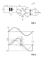
- Fig. 1 shows a first embodiment of a charging circuit 1 a according to the invention.
- the charging circuit 1 a comprises a transformer T with a primary coil L1 and a secondary coil L2 inductively coupled thereto, a bridge rectifier B connected to the secondary coil L2 of the transformer T via first opposing bridge points P11, P21, which is formed here with four diodes D1..D4 , and a charging output a connected to second opposing bridge points P12, P22 of the bridge rectifier B.
- a first capacitor C1 is connected between a first bridge point P11 and a second bridge point P12 is in addition a first capacitor C1 is connected.
- a second capacitor C2 is connected.
- an accumulator A is connected in this example, which is indeed a possible but not mandatory component of the charging circuit 1a.
- a current source I is connected to the input e connected to the primary coil L1, which is likewise a possible but not mandatory component of the charging circuit 1a.
- diode D1 turns off due to the voltage on capacitor C1.
- diodes D3 and D4 are off because of the direction of current I2.
- the current I2 flows at the beginning thus via the two capacitors C1 and C2, whereby the capacitor C1 is discharged and the capacitor C2 is charged.
- Fig. 2 are not the voltages UC1 and UC2 shown directly, but the voltage U2.
- the voltage U2 corresponds to the voltage UC2, in the second half period the negative voltage UC1.
- the capacitors C1, C2 results in comparison to a pure charging circuit with only one rectifier B now a lower effective load voltage U2, as from the Fig. 2 clearly shows.
- the capacitors C1, C2 are effective especially at high output voltages U2 DC , at low output voltage U2 DC but they are quickly reloaded and reduce the effective load voltage U2 thus less.
- the ratio of maximum value to minimum value of the voltage U2 is reduced in relation to the ratio of maximum value to minimum value of the DC output voltage U2 DC .
- the charging circuit 1a reaches the same power and coupling over the prior art thereby higher output voltages U2 DC .
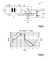
- the Fig. 3 shows an exemplary diagram of the DC output voltage U2 DC as a function of the input current I1 or IAC rms . in an inductive transmission system with weak coupling. Dashed line with short dashes is the rated current of the current source I (respectively a voltage source U), dashed with long dashes a course of a charging circuit only with a rectifier B (and without capacitors C1 and C2) and finally drawn through the course of the presented charging circuit 1a. It can clearly be seen that the charging circuit 1a initially behaves like a charging circuit without capacitors C1 and C2 when the DC output voltage U2 DC is low, ie they have little or no influence.
- this selection of the capacitance value at the power P and a secondary voltage U2 ⁇ U2 DCmax ensures that at each full-wave of the transformer voltage, all diodes D1..D4 as well as the capacitors C1, C2 carry a portion of the charging current. Only when U2 reaches or exceeds the value U2 DCmax flows through the parallel to the capacitors C1, C2 connected diodes D1, D4 no more power, and the charging circuit 1, 1a..1c acts as a pure, known from the literature, voltage doubler circuit ,
- the influence of the capacitors C1 and C2 on the charging circuit 1a is the greater the greater their capacitance value. Large capacitors C1 and C2 therefore lead to a greater increase in the output voltage U2 DC than small capacitors C1 and C2.
- the Fig. 4 now shows a further embodiment of a charging circuit 1 b, which of the in Fig. 1 Charging circuit 1a is very similar.
- this includes a third capacitor C3a connected between one terminal of the secondary coil L2 and a first bridge point P11, and a third capacitor C3b connected between the other terminal of the secondary coil L2 and the other first bridge point P21.
- a single larger capacitor is connected between a terminal of the secondary coil L2 and a first bridge point P11, P21.
- the charging circuit 1b comprises a fourth capacitor C4a connected between one terminal of the primary coil L1 of the transformer T and one terminal of the charging input e and a fourth capacitor C4b connected between the other terminal of the primary coil L1 of the transformer T and the other terminal of the charging input e ,
- a single larger capacitor between a terminal of a primary coil L1 of the transformer T and a terminal of the charging input e is connected.
- a parallel resonant circuit is provided instead of the primary-side series resonant circuit.
- a fourth capacitor is connected in parallel with the primary coil L1 of the transformer T.
- the combination of series and parallel connection results in a capacitive voltage divider, which causes a reduction of the input current I1, whereby the input voltage source U is relieved in an advantageous manner.
- the Fig. 5 shows yet another embodiment of a charging circuit 1 c, which in Fig. 2 illustrated charging circuit 1 b is very similar. In addition, however, this includes a fifth capacitor C5 connected between the first bridge points P11, P21. As a result, the voltage jump in the reversal of the current direction of the current I2 is avoided or mitigated. As a result, the voltage harmonics at the secondary coil L2 are also reduced.
- Fig. 6 shows the time courses of secondary current I2 and secondary voltage U2 without the fifth capacitor C5 in the bridge rectifier B (see also Fig. 2 ), and Fig. 7 shows the time courses of secondary current I2 and secondary voltage U2 with the fifth capacitor C5 in the bridge rectifier B. From the Fig. 7 it can be seen that the in Fig. 6 still occurring voltage jump when turning the current I2 now no longer occurs. Of course, the fifth capacitor C5 also in a charging circuit 1a after Fig. 1 be used.
- Fig. 8 now shows a motor vehicle 2, which includes the secondary-side components of a charging circuit 1 (ie, the handset MT) and connected to the charging output of the charging circuit 1 accumulator A, which at least partially serves the drive of the motor vehicle 2.
- the motor vehicle 2 comprises the secondary coil L2 of the transformer T, the bridge rectifier B, the first and second capacitors C1, C2, the accumulator A connected to the charging output a and optionally the third and fifth capacitors C3a, C3b, C5.
- the primary-side components of the charging circuit 1 which are arranged stationarily outside this motor vehicle 2 (ie with the stationary part ST of the charging circuit 1) results in a charging system 3. Specifically, the primary coil L1 of the transformer T and optionally the fourth capacitor C4a, C4b stationarily outside the motor vehicle 2 arranged.
- the advantages of the invention are particularly apparent because the coupling between the primary coil L1 and secondary coil L2 on the one hand can not be increased arbitrarily, on the other hand depending on the position of the vehicle. 2 to the primary coil L1 can vary.
- Inductive charging of electric vehicles via induction loops located in the ground can generally be divided into two categories, namely stationary charging of the parked vehicle and mobile charging while driving via induction lines laid in the roadway.
- primary coil L1 Via induction winding in the ground (primary coil L1) an alternating magnetic field in the frequency range 25 ... 150kHz (preferably 85kHz) is generated as soon as the system recognizes a ready to charge motor vehicle 2.
- a part of this field penetrates a "receiver coil” (secondary coil L2) in the vehicle 2 and thus enables contactless energy transmission as in a transformer T.
- a contactless charging circuit 1, 1 a..1 c is not bound to the application in a motor vehicle 2, but can be used in general.
- the charging circuit 1, 1a..1c then has a secondary part of the charging circuit 1, 1a..1c comprehensive handset MT and a separate from the handset MT, the primary-side components of the charging circuit 1, 1 a.1 c comprehensive stationary part ST on.
- the handset does not necessarily have to comprise an accumulator A, but may include the secondary coil L2 of the transformer T, the bridge rectifier B, the first and second capacitors C1, C2, the (free) charge output a, and optionally the third and fifth capacitors C3a, C3b, C5 include.
- the charging circuit 1, 1a..1c can in reality also comprise more components than shown. Furthermore, it is noted that the above embodiments and developments of the invention can be combined in any manner.
Landscapes
- Engineering & Computer Science (AREA)
- Power Engineering (AREA)
- Computer Networks & Wireless Communication (AREA)
- Transportation (AREA)
- Mechanical Engineering (AREA)
- Physics & Mathematics (AREA)
- Electromagnetism (AREA)
- Charge And Discharge Circuits For Batteries Or The Like (AREA)
- Electric Propulsion And Braking For Vehicles (AREA)
Priority Applications (3)
| Application Number | Priority Date | Filing Date | Title |
|---|---|---|---|
| EP14156254.6A EP2911264A1 (fr) | 2014-02-21 | 2014-02-21 | Circuit de charge pour un accumulateur doté d'une tension de sortie accrue |
| PCT/IB2015/051295 WO2015125114A1 (fr) | 2014-02-21 | 2015-02-20 | Circuit de charge pour accumulateur à tension de sortie élevée |
| DE112015000898.5T DE112015000898A5 (de) | 2014-02-21 | 2015-02-20 | Ladeschaltung für einen Akkumulator mit erhöhter Ausgangsspannung |
Applications Claiming Priority (1)
| Application Number | Priority Date | Filing Date | Title |
|---|---|---|---|
| EP14156254.6A EP2911264A1 (fr) | 2014-02-21 | 2014-02-21 | Circuit de charge pour un accumulateur doté d'une tension de sortie accrue |
Publications (1)
| Publication Number | Publication Date |
|---|---|
| EP2911264A1 true EP2911264A1 (fr) | 2015-08-26 |
Family
ID=50137587
Family Applications (1)
| Application Number | Title | Priority Date | Filing Date |
|---|---|---|---|
| EP14156254.6A Withdrawn EP2911264A1 (fr) | 2014-02-21 | 2014-02-21 | Circuit de charge pour un accumulateur doté d'une tension de sortie accrue |
Country Status (1)
| Country | Link |
|---|---|
| EP (1) | EP2911264A1 (fr) |
Cited By (1)
| Publication number | Priority date | Publication date | Assignee | Title |
|---|---|---|---|---|
| DE102016207929A1 (de) | 2016-05-09 | 2017-11-09 | Bayerische Motoren Werke Aktiengesellschaft | Sekundäreinheit mit Spannungsanpassung für induktives Laden |
Citations (8)
| Publication number | Priority date | Publication date | Assignee | Title |
|---|---|---|---|---|
| GB843843A (en) * | 1957-10-10 | 1960-08-10 | Pye Ltd | Power supply arrangement |
| US3046466A (en) * | 1958-11-03 | 1962-07-24 | Wilcox Electric Company Inc | Voltage regulated power supplies |
| EP0633652A2 (fr) * | 1993-07-09 | 1995-01-11 | Sgs-Thomson Microelectronics Pte Ltd. | Circuit d'alimentation à tension continue |
| US20090152954A1 (en) * | 2007-07-17 | 2009-06-18 | Triet Tu Le | RF energy harvesting circuit |
| US20110199028A1 (en) * | 2010-02-12 | 2011-08-18 | Semiconductor Energy Laboratory Co., Ltd. | Moving Object, Wireless Power Feeding System, and Wireless Power Feeding Method |
| US20120007435A1 (en) * | 2010-06-30 | 2012-01-12 | Panasonic Corporation | Power generator and power generation system |
| US20130069440A1 (en) * | 2011-09-20 | 2013-03-21 | Kabushiki Kaisha Toshiba | Incoming circuit using magnetic resonant coupling |
| WO2013136409A1 (fr) * | 2012-03-12 | 2013-09-19 | パイオニア株式会社 | Dispositif de réception d'énergie ainsi que procédé de commande d'un dispositif de réception d'énergie et programme informatique |
-
2014
- 2014-02-21 EP EP14156254.6A patent/EP2911264A1/fr not_active Withdrawn
Patent Citations (8)
| Publication number | Priority date | Publication date | Assignee | Title |
|---|---|---|---|---|
| GB843843A (en) * | 1957-10-10 | 1960-08-10 | Pye Ltd | Power supply arrangement |
| US3046466A (en) * | 1958-11-03 | 1962-07-24 | Wilcox Electric Company Inc | Voltage regulated power supplies |
| EP0633652A2 (fr) * | 1993-07-09 | 1995-01-11 | Sgs-Thomson Microelectronics Pte Ltd. | Circuit d'alimentation à tension continue |
| US20090152954A1 (en) * | 2007-07-17 | 2009-06-18 | Triet Tu Le | RF energy harvesting circuit |
| US20110199028A1 (en) * | 2010-02-12 | 2011-08-18 | Semiconductor Energy Laboratory Co., Ltd. | Moving Object, Wireless Power Feeding System, and Wireless Power Feeding Method |
| US20120007435A1 (en) * | 2010-06-30 | 2012-01-12 | Panasonic Corporation | Power generator and power generation system |
| US20130069440A1 (en) * | 2011-09-20 | 2013-03-21 | Kabushiki Kaisha Toshiba | Incoming circuit using magnetic resonant coupling |
| WO2013136409A1 (fr) * | 2012-03-12 | 2013-09-19 | パイオニア株式会社 | Dispositif de réception d'énergie ainsi que procédé de commande d'un dispositif de réception d'énergie et programme informatique |
Cited By (1)
| Publication number | Priority date | Publication date | Assignee | Title |
|---|---|---|---|---|
| DE102016207929A1 (de) | 2016-05-09 | 2017-11-09 | Bayerische Motoren Werke Aktiengesellschaft | Sekundäreinheit mit Spannungsanpassung für induktives Laden |
Similar Documents
| Publication | Publication Date | Title |
|---|---|---|
| EP2783458B1 (fr) | Redresseur commandé doté d'un pont b2 et d'un seul dispositif de commutation | |
| DE112019001196B4 (de) | Kontaktlose energieübertragungsvorrichtung | |
| WO2017125204A1 (fr) | Convertisseur continu/continu bidirectionnel et procédé de charge du condensateur de circuit intermédiaire d'un convertisseur continu/continu de la batterie basse tension | |
| EP3134952B1 (fr) | Système de transmission et procédé de charge par induction d'un véhicule à propulsion électrique, et ensemble véhicule | |
| EP2895734B1 (fr) | Système d'allumage conçu pour un moteur à combustion interne | |
| EP2868516A1 (fr) | Procédé de régulation de l'énergie transmise entre deux résonateurs d'un système de transmission sans contact de l'énergie et agencement de résonateurs | |
| EP2299572A1 (fr) | Démarrage d'un convertisseur CC/CC avec un transformateur à haute fréquence | |
| DE102013217816A1 (de) | Vorrichtung zur induktiven Energieübertragung und Verfahren zum Betreiben einer Vorrichtung zur induktiven Energieübertragung | |
| EP3615139B1 (fr) | Dispositif de défribillation | |
| EP2895735A1 (fr) | Système d'allumage conçu pour un moteur à combustion interne | |
| WO2020043883A1 (fr) | Procédé et dispositif pour adapter la tension du condensateur de filtrage d'un convertisseur cc-cc avant la connexion d'une batterie haute tension | |
| EP3921935A1 (fr) | Convertisseur continu-continu doté d'un condensateur de circuit d'oscillations secondaire, ainsi que procédé de fonctionnement d'un convertisseur continu-continu | |
| WO2016055180A1 (fr) | Procédé et système de charge sans contact d'un objet fonctionnant sur batterie | |
| DE102018118080A1 (de) | Aktiver Sperrwandler mit variabler Resonanzfrequenz | |
| WO2015125114A1 (fr) | Circuit de charge pour accumulateur à tension de sortie élevée | |
| WO2020070115A1 (fr) | Dispositif de transfert d'énergie par induction sans contact, en particulier destiné à des procédés de chargement par induction dans des véhicules automobiles | |
| DE112015000884T5 (de) | Induktive Ladevorrichtung | |
| WO2014060302A2 (fr) | Onduleur avec un circuit d'adaptation pour des hautes tensions d'entrée continues variables et emploi du circuit d'adaptation | |
| EP2911264A1 (fr) | Circuit de charge pour un accumulateur doté d'une tension de sortie accrue | |
| DE102011005446A1 (de) | Schaltungsanordnung mit Wechselrichter zur Spannungsversorgung einer Röntgenröhre und zugehöriges Verfahren | |
| EP2999079A1 (fr) | Systeme et procede de fonctionnement d'un systeme destine a la transmission d'energie inductive vers un consommateur electrique | |
| WO2015177657A1 (fr) | Dispositif de charge inductive et commande ainsi que procédé permettant de faire fonctionner ledit dispositif | |
| EP2670040A1 (fr) | Agencement d'alimentation électrique avec un onduleur pour la génération de courant alternatif monophasé | |
| EP2910403A1 (fr) | Dispositif de charge inductif | |
| EP3539814A1 (fr) | Dispositif de charge pour véhicules automobiles à commande de circuit sur le côté récepteur |
Legal Events
| Date | Code | Title | Description |
|---|---|---|---|
| PUAI | Public reference made under article 153(3) epc to a published international application that has entered the european phase |
Free format text: ORIGINAL CODE: 0009012 |
|
| AK | Designated contracting states |
Kind code of ref document: A1 Designated state(s): AL AT BE BG CH CY CZ DE DK EE ES FI FR GB GR HR HU IE IS IT LI LT LU LV MC MK MT NL NO PL PT RO RS SE SI SK SM TR |
|
| AX | Request for extension of the european patent |
Extension state: BA ME |
|
| STAA | Information on the status of an ep patent application or granted ep patent |
Free format text: STATUS: THE APPLICATION IS DEEMED TO BE WITHDRAWN |
|
| 18D | Application deemed to be withdrawn |
Effective date: 20160227 |