EP2911291A2 - Procédé et système de commande de machine synchrone en tant que générateur/démarreur - Google Patents
Procédé et système de commande de machine synchrone en tant que générateur/démarreur Download PDFInfo
- Publication number
- EP2911291A2 EP2911291A2 EP14200356.5A EP14200356A EP2911291A2 EP 2911291 A2 EP2911291 A2 EP 2911291A2 EP 14200356 A EP14200356 A EP 14200356A EP 2911291 A2 EP2911291 A2 EP 2911291A2
- Authority
- EP
- European Patent Office
- Prior art keywords
- winding
- starter
- generator
- field
- exciter field
- Prior art date
- Legal status (The legal status is an assumption and is not a legal conclusion. Google has not performed a legal analysis and makes no representation as to the accuracy of the status listed.)
- Granted
Links
Images




Classifications
-
- H—ELECTRICITY
- H02—GENERATION; CONVERSION OR DISTRIBUTION OF ELECTRIC POWER
- H02P—CONTROL OR REGULATION OF ELECTRIC MOTORS, ELECTRIC GENERATORS OR DYNAMO-ELECTRIC CONVERTERS; CONTROLLING TRANSFORMERS, REACTORS OR CHOKE COILS
- H02P31/00—Arrangements for regulating or controlling electric motors not provided for in groups H02P1/00 - H02P5/00, H02P7/00 or H02P21/00 - H02P29/00
-
- F—MECHANICAL ENGINEERING; LIGHTING; HEATING; WEAPONS; BLASTING
- F02—COMBUSTION ENGINES; HOT-GAS OR COMBUSTION-PRODUCT ENGINE PLANTS
- F02N—STARTING OF COMBUSTION ENGINES; STARTING AIDS FOR SUCH ENGINES, NOT OTHERWISE PROVIDED FOR
- F02N11/00—Starting of engines by means of electric motors
- F02N11/04—Starting of engines by means of electric motors the motors being associated with current generators
-
- H—ELECTRICITY
- H02—GENERATION; CONVERSION OR DISTRIBUTION OF ELECTRIC POWER
- H02P—CONTROL OR REGULATION OF ELECTRIC MOTORS, ELECTRIC GENERATORS OR DYNAMO-ELECTRIC CONVERTERS; CONTROLLING TRANSFORMERS, REACTORS OR CHOKE COILS
- H02P9/00—Arrangements for controlling electric generators for the purpose of obtaining a desired output
- H02P9/08—Control of generator circuit during starting or stopping of driving means, e.g. for initiating excitation
-
- H—ELECTRICITY
- H02—GENERATION; CONVERSION OR DISTRIBUTION OF ELECTRIC POWER
- H02P—CONTROL OR REGULATION OF ELECTRIC MOTORS, ELECTRIC GENERATORS OR DYNAMO-ELECTRIC CONVERTERS; CONTROLLING TRANSFORMERS, REACTORS OR CHOKE COILS
- H02P9/00—Arrangements for controlling electric generators for the purpose of obtaining a desired output
- H02P9/14—Arrangements for controlling electric generators for the purpose of obtaining a desired output by variation of field
-
- F—MECHANICAL ENGINEERING; LIGHTING; HEATING; WEAPONS; BLASTING
- F02—COMBUSTION ENGINES; HOT-GAS OR COMBUSTION-PRODUCT ENGINE PLANTS
- F02C—GAS-TURBINE PLANTS; AIR INTAKES FOR JET-PROPULSION PLANTS; CONTROLLING FUEL SUPPLY IN AIR-BREATHING JET-PROPULSION PLANTS
- F02C7/00—Features, components parts, details or accessories, not provided for in, or of interest apart form groups F02C1/00 - F02C6/00; Air intakes for jet-propulsion plants
- F02C7/26—Starting; Ignition
- F02C7/268—Starting drives for the rotor, acting directly on the rotor of the gas turbine to be started
-
- F—MECHANICAL ENGINEERING; LIGHTING; HEATING; WEAPONS; BLASTING
- F02—COMBUSTION ENGINES; HOT-GAS OR COMBUSTION-PRODUCT ENGINE PLANTS
- F02N—STARTING OF COMBUSTION ENGINES; STARTING AIDS FOR SUCH ENGINES, NOT OTHERWISE PROVIDED FOR
- F02N11/00—Starting of engines by means of electric motors
- F02N11/08—Circuits specially adapted for starting of engines
- F02N2011/0881—Components of the circuit not provided for by previous groups
- F02N2011/0896—Inverters for electric machines, e.g. starter-generators
-
- H—ELECTRICITY
- H02—GENERATION; CONVERSION OR DISTRIBUTION OF ELECTRIC POWER
- H02P—CONTROL OR REGULATION OF ELECTRIC MOTORS, ELECTRIC GENERATORS OR DYNAMO-ELECTRIC CONVERTERS; CONTROLLING TRANSFORMERS, REACTORS OR CHOKE COILS
- H02P2101/00—Special adaptation of control arrangements for generators
- H02P2101/30—Special adaptation of control arrangements for generators for aircraft
Definitions
- Vehicles such as aircraft have an electromechanical machine functioning as a generator to provide electrical power to equipment loads throughout the aircraft.
- the primary function of the generator is to generate electricity, but the electromechanical machine when coupled to an engine may also be used as a starting motor to start the engine.
- mechanical energy is converted into electrical energy using electromagnetic induction. Reverse conversion of electrical energy into mechanical energy to provide torque to start the engine is done by the electric starting motor. Therefore, one electromechanical machine can operate as both an electric starting motor to drive the engine up to the desired idle speed and as a generator to provide electrical power to the aircraft which helps to reduce the cost and weight of the aircraft.
- the parts of the electromechanical machine are expressed in either mechanical or electrical terms which may be used interchangeably or in combination.
- the two principle components are the rotor and stator where the rotor is the rotating part of the generator or the starting motor and the stator is the stationary part of the generator or starting motor.
- the rotor of the electromechanical machine rotates within a magnetic field produced by permanent magnets or by field coils where current must flow in the field coils to generate the magnetic field.
- excitation The process of generating a magnetic field with an electric current is called excitation.
- U.S. Pat. No. 4,743,777 to Shilling et al. teaches that the rotor of these starter generator systems carries a main field winding and a three phase exciter armature winding along with a rectifier for rectifying the output of the exciter armature winding to provide DC excitation for the rotating DC main field winding.
- the stator includes a main armature winding and an exciter section of two windings.
- the main armature winding is magnetically coupled to the main field winding on the rotor.
- the exciter section of two windings on the stator includes a first exciter field winding and a second exciter field winding that are both mounted to be magnetically coupled to the exciter armature windings of the rotor.
- the first exciter field winding is a multiple phase AC exciter field winding and the second exciter field winding is a DC exciter field winding.
- the AC exciter field winding receives power from an external power source.
- DC power is supplied to the DC exciter field winding.
- synchronous brushless machines utilizing two exciter field windings have a high number of components and require complicated controls which hurt reliability.
- the field voltage of the generator is either increasing or decreasing due to the effect of variation of back electro-motive-force (back EMF) resulted from changing speed of the rotor during the starter mode.
- back EMF back electro-motive-force
- a starter-generator system includes a rotor mounted for rotation with respect to the stator, a main field winding, an exciter field armature winding, and a rectifier for rectifying an output from the exciter field armature winding to provide DC excitation for the main field winding.
- the main field winding, the exciter field armature winding, and the rectifier are mounted for rotation with the rotor.
- a main armature winding is mounted on the stator and magnetically coupled to the main field winding.
- a single exciter field stator winding is configured to provide a single excitation field to magnetically couple with the exciter field armature winding when the starter-generator system is operating in both a starter mode and in a generator mode.
- a starter-generator system includes a rotor mounted for rotation with respect to a stator, a main field winding, and an exciter field armature winding.
- a rectifier rectifies an output from the exciter field armature winding to provide DC excitation for the main field winding.
- the main field winding, the exciter field armature winding, and the rectifier are mounted for rotation with the rotor.
- a main armature winding is mounted on the stator and magnetically coupled to the main field winding.
- a single exciter field stator winding is configured to be energized by high frequency alternating current to provide a single excitation field to magnetically couple with the exciter field armature winding when the starter-generator system is operating in both a starter mode and in a generator mode.
- the frequencies of voltage waveforms at the exciter field armature winding vary with the speed of the rotor, the voltage waveforms at the exciter field armature winding have substantially the same amplitude as the speed of the rotor varies, and an amplitude of a voltage waveform at the main field winding remains constant as the speed of the rotor varies.
- a method for controlling a synchronous brushless machine as a generator and a starter motor includes providing a single exciter field stator winding and an exciter field armature winding. The method then includes energizing the single exciter field stator winding with a high frequency alternating current. Next, the method includes providing a single excitation field to magnetically couple the single exciter field stator to the exciter field armature winding while the synchronous brushless machine operates in either a starter mode or in a generator mode.
- the method may also include varying frequencies of voltage waveforms at an exciter field armature winding while the voltage waveforms have substantially the same amplitude as a speed of the rotor varies. Also, the method could include maintaining an amplitude of a voltage waveform at a main field winding while the speed of the rotor varies.
- the following detailed description is directed to bidirectional energy conversion by brushless electronic systems that convert electrical energy to mechanical energy in a starter mode and mechanical energy to electrical energy in a generator mode.
- the disclosure relates to a starter-generator system having a single exciter field stator winding.
- the single exciter field stator winding is utilized during operation of the starter-generator in both the starter mode and the generator mode.
- the present disclosure is susceptible of embodiment in many different forms.
- a three-phase exciter stator winding on the stator is required in the starter mode and a single phase winding on the stator in the generator mode.
- only one simple exciter field winding for field excitation is needed on the stator in both the starter mode and the generator mode. This reduces the volume and weight of the exciter stage and therefore the starter-generator system.
- improved stability control is also provided while operating the starter-generator in the starter mode.
- Vehicles such as aircraft may have one or more engines requiring the use of a starter-generator system having starter motor and a controller to start each engine. Switching control signals are generated for parallel transistors of the controller. In one or more confirmations, parallel transistors are excitation source implementations. For example, multiple H-bridges may be paralleled. In one or more configurations of the starter-generator system, the controller could include multiple parallel transistors and multiple controllers could be combined in parallel to provide a customized and correctly sized control system where different controllers could be tasked according to the needs of the vehicle.
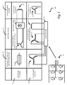
- FIG. 1 illustrates a chart 100 generally depicting the spatial relationship of three stages of a conventional three-stage synchronous brushless machine with excitation control.
- Chart 100 corresponds with a conventional three stage synchronous brushless machine and, therefore, each of the three stages corresponds with a column of chart 100.
- the first stage is the permanent magnet generator stage 10 and is on the left
- the second stage is the exciter stage 12 and is in the middle
- the third stage is the main machine stage 14 and is on the right.
- an upper row corresponds with a rotor or a rotating section 16 of the three stage synchronous brushless machine and a lower row corresponds with a stator or a stationary section 18 of the three stage synchronous brushless machine.
- a two or three stage synchronous brushless machine may be referred to as a two stage starter-generator system or a three stage starter-generator system, respectively, or simply as a brushless machine.
- the permanent magnet generator stage 10 includes a permanent magnet 22 in the rotating section 16 and a three phase alternating current (AC) winding 24 in the stationary section 18.
- the main machine stage 14 includes a main field winding 26 in rotating section 16 and a main armature winding 28 in the stationary section 18.
- the main armature winding 28 is a three phase AC armature and is preferably connected to an AC bus when the brushless machine is operated in the starter mode.
- the permanent magnet generator stage 10 is activated, via a co-shafted prime mover, to provide the energy required by the main field winding 26 so that the main armature winding 28 becomes the main energy source for providing electrical power throughout the aircraft.
- the stationary section 18 of the exciter stage 12 includes two different exciter field stator windings: a three phase AC winding 30 and a single phase direct current (DC) exciter field stator winding 32. Whether the three phase AC winding 30 or the single phase DC exciter field stator winding 32 is used depends on whether the brushless machine is being operated in the starter mode or in the generator mode.
- the rotating section 16 of the exciter stage 12 includes an exciter field armature winding 36 and a rectifier 38.
- the controller 40 includes a three leg, six switch inverter 42.
- the controller 40 with the inverter 42 provides excitation sources of either a three phase AC current as well as a DC current excitation to the three phase AC exciter field stator winding 30, or a DC current excitation to the single phase DC exciter field stator winding 32, respectively.
- the controller 40 When operating in the starter mode, the controller 40 provides AC currents to energize the three phase AC exciter field stator winding 30 which generates an excitation field, which may simply be referred to as a magnetic field, to magnetically couple the three phase AC exciter field stator winding 30 to the exciter field armature winding 36 in the rotating section 16 of the exciter stage 12.
- the main field excitation current at main filed winding 26 is obtained as a result of rectification by rectifier 38 of 3-phase currents at the exciter field armature windings 36.
- the main field excitation current interacts with the rotating magnetic field generated by 3-phase power input at the main armature winding 28, thus causing the rotor to rotate, and converting the electrical energy into mechanical energy.
- the three phase AC excitation on the three phase AC exciter field stator winding 30 will have either forward or reverse phase sequence relative to the rotation of the rotor. Either choice of phase sequences has disadvantages. If the forward sequence is chosen, the magnetic field created by the three phase AC exciter field stator winding 30 has the same rotating direction as the rotor. As a result, the excitation on the main machine stage 14 will decrease as the speed of the rotor increases which is not desirable for a starting process. If the reverse sequence is chosen, the torque created by the excitation stage 12 will oppose main machine stage torque, which is also not desirable for the starting process. The disclosure below identifies how to obtain a constant main field voltage to eliminate the disadvantage associated with the forward and reverse phase sequencing relative to the rotation of the rotor.
- the controller 40 energizes the single phase DC exciter field stator winding 32 rather than the three phase AC exciter field stator winding 30.
- the DC exciter field stator winding 32 creates an excitation field to magnetically couple with the exciter field armature winding 36.
- the power source for the DC exciter field stator winding 32 is from the three phase stator armature windings 24 of the permanent magnet motor stage 10.
- the prime mover turns the shaft, thus the permanent magnet 22 rotates, which creates a rotating magnetic field. This induces currents within the permanent magnet motor armature windings 24.
- the three phase currents from the three phase stator armature windings 24 are then conducted to a rectifier within the controller 40.
- the rectified current a DC current, provides an excitation current at the DC exciter field stator winding 32 in the stationary section 18 of the excitation stage 12.
- Three phase AC power from the exciter field armature winding 36 is rectified by rectifier 38 to provide DC current to the main field winding 26 in the rotating section 16 of the main machine stage 14.
- the main field winding 26 creates a second excitation field to magnetically couple the main field winding 26 to the main armature winding 28 in the stationary section 18 of the main machine stage 14.
- three phase AC current is provided from the main armature winding 28 to an AC power bus of a vehicle.
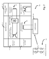
- FIG. 2 illustrates a chart 200 generally depicting the spatial relationship of a two stage.
- chart 200 is distinguishable from chart 100 in that the stationary section 18 of the exciter stage 12 includes a single excited field stator winding 132. Only the single exciter field stator winding 132 provides the excitation field to magnetically couple with the exciter field armature winding 36 in both the starter mode and the generator mode. The single exciter field stator winding 132 is energized by the controller 140.
- the controller 140 preferably includes an H-bridge converter 142 as the excitation source providing a high frequency alternating current (greater than a fundamental electrical frequency of the starter-generator, for example, substantially greater than 400 Hertz) excitation to the single exciter field stator winding 132 in both the starter mode and the generator mode of the brushless machine.
- a high frequency alternating current greater than a fundamental electrical frequency of the starter-generator, for example, substantially greater than 400 Hertz
- frequency of the excitation voltage from the H-bridge converter 142 of the controller 140 could be about 10 kilohertz (kHz) alternating current to energize the single exciter field stator winding 132.
- the frequency of the alternating current is substantially higher that the current frequency of the main armature winding 28 which is about 400 Hz to about 800 Hz.
- the exciter field armature winding 36 can be a single phase winding or a multi-phase winding and, therefore, create a transformer effect.
- a single phase exciter field armature winding 36 and the single exciter field stator winding define a transformer configured to transform an alternating current input voltage between the single exciter field stator winding 132 and the exciter field armature winding 36.
- the exciter field armature winding 36 in some configurations, for example, may be a two phase winding or have more than three phases.
- FIG. 3 illustrates a linear view of the two-stage synchronous brushless machine of FIG. 2 with the single excited field stator winding 132.
- Utilizing only the single exciter field stator winding 132 in both the starter mode and the generator mode reduces volume and weight and also reduces the number of control components which increases reliability. Also, requiring the use of only one excitation source in both the starter mode and the generator mode results in less excitation source and control complexity. Because of the substantially higher excitation frequency relative to the main armature current frequency, a steady main field voltage can be achieved which improves stability control during the starter mode. Also, by using high frequency excitation the exciter field armature winding 36 and back iron weight may be reduced.
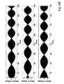
- the high frequency (for example about 10kHz) excitation voltage output of the H-bridge converter 142 is an alternating excitation square wave voltage V 0 , as shown in FIG. 4 .
- a square wave is plotted because the H-bridge converter 142 is used.
- a high frequency sine-wave, or any high frequency alternating current wave can also be used as an excitation source.
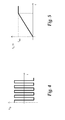
- FIG. 5 illustrates a speed curve f R (t) corresponding with a machine rotor speed f RO over time.
- the speed curve f R (t) includes a linear ramp beginning from zero speed.
- the speed of the rotor f RO reaches a steady or constant speed at some point in time.
- the speed of the rotor is shown by the armature current frequency which is typically at a steady state of about 400 Hz.
- FIG. 6A depicted along with the exciter field armature 36 are the three phase exciter armature voltages V 1 , V 2 and V 3 .
- Waveforms of the three phase exciter field armature voltages V 1 , V 2 and V 3 are illustrated in FIG. 6A .
- the waveforms of the phase exciter armature voltages V 1 , V 2 and V 3 are interleaved and each have the same amplitude at a particular point in time.
- the excitation voltage V 0 of the excitation source has a high frequency which is constant, the frequency of each of the three phase exciter field armature voltages V 1 , V 2 and V 3 changes.
- FIG. 6A is an expanded view of the waveforms of FIG. 6A
- FIG. 6C is an expanded view of the waveforms of FIG. 6B
- FIGs 6A and 6B better illustrate that the waveforms of V 1 , V 2 and V 3 are interleaved by about 120 degrees, have the same amplitude at a particular point in time, and are modulated with a frequency of about 0 to 400Hz which corresponds with the machine rotor speed f RO .
- FIG. 3 also depicts a main generator field voltage V 4 in association with the main field winding 26.
- FIG. 7 then illustrates verification results of the waveform of the main generator field voltage V 4 .
- the waveform of the main generator field voltage V 4 includes ripples.
- the steady value of the main generator field voltage V 4 is independent of the machine rotor speed f RO , but the frequency of the ripples correspond with the machine rotor speed f RO .
- the ripples become faster as a function of the machine rotor speed f RO . This is distinguishable from the excitation methods disclosed in association with the brushless machine of FIG. 1 which has either an increasing or decreasing main generator field voltage.
- FIG. 8 illustrates a comparison of the envelope of the main field voltage envelope V 4 versus the envelopes of conventional excitation methods of the brushless machine disclosed in association with FIG. 1 .
- the amplitude of the voltage envelope is a function of machine rotor speed f RO .
- the increasing line 180 corresponds with the conventional excitation method using reverse phase sequence
- the decreasing line 182 corresponds with the conventional excitation method using forward phase sequence.
- the amplitude of the main generator field voltage V 4 is constant as depicted by line 188.
- Constant main generator field voltage V 4 is preferred for controlling a brushless machine as a stating motor for an engine such as an aircraft engine.
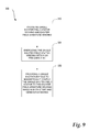
- FIG. 9 illustrates a method 300 for method for controlling a synchronous brushless machine having a rotor and stator as a generator and as a starter motor. Unless otherwise indicated, more or fewer operations may be performed than shown in the figures and described herein. Additionally, unless otherwise indicated, these operations may also be performed in a different order than those described herein.
- the method 300 starts at operation 310 where a single exciter field stator winding and an exciter field armature winding is provided.
- operation 320 includes energizing the single exciter field stator winding 132 with a high frequency alternating current.
- Operation 330 includes providing a single excitation field to magnetically couple the single exciter field stator winding 132 to the exciter field armature winding 36 while the synchronous brushless machine operates in both a starter mode and in a generator mode.
- the method 300 may also include the operation of maintaining the amplitude of a voltage waveform at a main field winding while a speed of the rotor varies.
- the method 300 may also include the operation of varying frequencies of voltage waveforms at an exciter field armature winding 36 while the voltage waveforms have substantially the same amplitude as a speed of the rotor varies.
- Method 300 may also include the operation of driving the single exciter field stator winding 132 with an H-bridge converter 142.
- Method 300 may also include the operation of starting an engine of an aircraft while the synchronous brushless machine is in the starter mode and the operation of powering equipment loads of an aircraft while the synchronous brushless machine is in the generator mode.
Landscapes
- Engineering & Computer Science (AREA)
- Power Engineering (AREA)
- Chemical & Material Sciences (AREA)
- Combustion & Propulsion (AREA)
- Mechanical Engineering (AREA)
- General Engineering & Computer Science (AREA)
- Control Of Eletrric Generators (AREA)
- Synchronous Machinery (AREA)
Applications Claiming Priority (1)
| Application Number | Priority Date | Filing Date | Title |
|---|---|---|---|
| US14/187,851 US9209741B2 (en) | 2014-02-24 | 2014-02-24 | Method and system for controlling synchronous machine as generator/starter |
Publications (3)
| Publication Number | Publication Date |
|---|---|
| EP2911291A2 true EP2911291A2 (fr) | 2015-08-26 |
| EP2911291A3 EP2911291A3 (fr) | 2015-12-09 |
| EP2911291B1 EP2911291B1 (fr) | 2019-08-14 |
Family
ID=52146347
Family Applications (1)
| Application Number | Title | Priority Date | Filing Date |
|---|---|---|---|
| EP14200356.5A Active EP2911291B1 (fr) | 2014-02-24 | 2014-12-26 | Procédé et système de commande de machine synchrone en tant que générateur/démarreur |
Country Status (2)
| Country | Link |
|---|---|
| US (1) | US9209741B2 (fr) |
| EP (1) | EP2911291B1 (fr) |
Cited By (2)
| Publication number | Priority date | Publication date | Assignee | Title |
|---|---|---|---|---|
| EP3627689A1 (fr) * | 2018-09-21 | 2020-03-25 | Hamilton Sundstrand Corporation | Système et procédé d'entraînement électrique d'un moteur à turbine à gaz par l'intermédiaire d'une machine synchrone à champ bobiné assisté par un générateur à aimant permanent |
| CN113162496A (zh) * | 2021-05-06 | 2021-07-23 | 西北工业大学 | 航空两级式高压直流起动发电系统的拓扑结构及控制方法 |
Families Citing this family (33)
| Publication number | Priority date | Publication date | Assignee | Title |
|---|---|---|---|---|
| US9325229B2 (en) * | 2013-03-15 | 2016-04-26 | Hamilton Sundstrand Corporation | Generator architecture with PMG exciter and main field rotating power converter |
| US9252695B2 (en) * | 2014-03-12 | 2016-02-02 | General Electric Company | Brushless permanent magnet generator plus auxiliary voltage source constant potential exciter |
| EP2963803A1 (fr) * | 2014-07-01 | 2016-01-06 | Siemens Aktiengesellschaft | Alimentation d'une machine synchrone en courant d'excitation |
| US10305356B2 (en) | 2014-09-26 | 2019-05-28 | The Boeing Company | Synchronous machine with common motor/generator exciter stage |
| FR3052307B1 (fr) * | 2016-06-07 | 2019-07-12 | Thales | Demarreur generateur sans balais |
| US10486537B2 (en) | 2016-08-29 | 2019-11-26 | Hamilton Sundstrand Corporation | Power generating systems having synchronous generator multiplex windings and multilevel inverters |
| US11043880B2 (en) | 2016-11-10 | 2021-06-22 | Hamilton Sunstrand Corporation | Electric power generating system with a synchronous generator |
| US10498274B2 (en) | 2016-11-10 | 2019-12-03 | Hamilton Sundstrand Corporation | High voltage direct current system for a vehicle |
| WO2018101158A1 (fr) * | 2016-12-02 | 2018-06-07 | 梨木 政行 | Moteur et dispositif de commande associé |
| JP7128456B2 (ja) * | 2017-01-16 | 2022-08-31 | 政行 梨木 | モータ |
| DE102017201687A1 (de) * | 2017-02-02 | 2018-08-02 | Siemens Aktiengesellschaft | Regelbare Spannungserzeugungsvorrichtung und Verfahren zum Betreiben einer regelbaren Spannungserzeugungsvorrichtung |
| EP3392500B1 (fr) | 2017-04-18 | 2022-07-27 | GE Avio S.r.l. | Machine synchrone à réluctance à deux enroulements composée d'un enroulement d'excitation et d'un enroulement de puissance séparé |
| US10425026B2 (en) * | 2017-11-21 | 2019-09-24 | The Boeing Company | Independent speed variable frequency alternating current generator |
| US10454404B2 (en) * | 2017-11-22 | 2019-10-22 | The Boeing Company | Generator field exciter system |
| US10454278B2 (en) | 2018-01-09 | 2019-10-22 | The Boeing Company | Independent speed variable frequency based electrified propulsion system architecture |
| US10547269B2 (en) * | 2018-05-17 | 2020-01-28 | The Boeing Company | Variable frequency independent speed motor |
| WO2020178863A1 (fr) * | 2019-03-06 | 2020-09-10 | Sedemac Mechatronics Pvt Ltd | Procédé de démarrage d'un générateur sans balai triphasé et système associé |
| WO2020178864A1 (fr) * | 2019-03-06 | 2020-09-10 | Sedemac Mechatronics Pvt Ltd | Procédé de démarrage d'une génératrice monophasée à balais et système associé |
| US10934880B1 (en) * | 2019-09-04 | 2021-03-02 | The Boeing Company | Electrical generation from turbine engines |
| US11025183B2 (en) * | 2019-10-01 | 2021-06-01 | The Boeing Company | Independent-speed-variable-frequency-generator-based constant frequency and narrow-band variable frequency power systems and methods |
| CN111120176A (zh) * | 2020-01-08 | 2020-05-08 | 北京贝源白氏电机研究所 | 一种内燃机发电机及其一机两用控制方法 |
| US11362567B2 (en) * | 2020-01-16 | 2022-06-14 | The Boeing Company | Electrical power generation from turbine engines |
| US11619956B2 (en) * | 2020-03-13 | 2023-04-04 | Hamilton Sundstrand Corporation | Nonlinear trim head power supply with a wide input range and a high efficiency |
| CN111293846B (zh) * | 2020-03-31 | 2025-09-19 | 彭平高 | 差频式高频电机 |
| US11565824B2 (en) * | 2020-04-08 | 2023-01-31 | General Electric Company | Electric generator |
| US11193426B2 (en) | 2020-04-16 | 2021-12-07 | The Boeing Company | Electrically geared turbofan |
| CN112653365B (zh) * | 2020-12-04 | 2022-10-04 | 南京航空航天大学 | 三级式无刷同步电机起动过程交直流励磁平滑切换方法 |
| KR20220082733A (ko) | 2020-12-10 | 2022-06-17 | 더 보잉 컴파니 | 다이렉트 드라이브 전기적-기어식 터보팬 |
| CN113676105B (zh) * | 2021-07-27 | 2023-05-09 | 南京航空航天大学 | 一种基于主励磁机励磁电流的同步解耦信号生成方法 |
| US12155323B2 (en) | 2022-07-11 | 2024-11-26 | Google Llc | Multi generator synchronization system |
| US12224700B2 (en) | 2023-01-13 | 2025-02-11 | Hamilton Sundstrand Corporation | Starter/generator arrangements for gas turbine engines |
| US20250035047A1 (en) * | 2023-07-28 | 2025-01-30 | Rolls-Royce Corporation | Fault tolerant electrical starting of gas-turbine engine |
| CN117578928B (zh) * | 2023-12-08 | 2025-03-25 | 南京航空航天大学 | 一种用于航空三级式起动发电机的单相交直流励磁系统 |
Family Cites Families (26)
| Publication number | Priority date | Publication date | Assignee | Title |
|---|---|---|---|---|
| US4093869A (en) * | 1976-04-13 | 1978-06-06 | Westinghouse Electric Corp. | Quadrature axis field brushless exciter |
| US4743777A (en) | 1986-03-07 | 1988-05-10 | Westinghouse Electric Corp. | Starter generator system with two stator exciter windings |
| US4772802A (en) * | 1987-08-19 | 1988-09-20 | Sundstrand Corporation | Starting/generating system |
| US4982123A (en) * | 1989-11-17 | 1991-01-01 | Sunstrand Corporation | Integrated exciter generator and rotating transformer |
| US5013929A (en) * | 1989-11-22 | 1991-05-07 | Sundstrand Corporation | Power conversion system having prime mover start capability |
| US5334898A (en) * | 1991-09-30 | 1994-08-02 | Dymytro Skybyk | Polyphase brushless DC and AC synchronous machines |
| US5594322A (en) * | 1993-05-12 | 1997-01-14 | Sundstrand Corporation | Starter/generator system with variable-frequency exciter control |
| US5581168A (en) * | 1993-05-12 | 1996-12-03 | Sundstrand Corporation | Starter/generator system with DC link current control |
| US5493200A (en) * | 1993-05-12 | 1996-02-20 | Sundstrand Corporation | Control for a brushless generator |
| US20020166324A1 (en) * | 1998-04-02 | 2002-11-14 | Capstone Turbine Corporation | Integrated turbine power generation system having low pressure supplemental catalytic reactor |
| US6906479B2 (en) * | 2002-08-06 | 2005-06-14 | Honeywell International, Inc. | Gas turbine engine starter generator with multiple windings on each exciter stator pole |
| US6847194B2 (en) * | 2002-09-20 | 2005-01-25 | Honeywell International Inc. | Electric start for a prime mover |
| US6933704B2 (en) * | 2002-10-11 | 2005-08-23 | Siemens Westinghouse Power Corporation | Slip-inducing rotation starting exciter for turbine generator |
| US6998726B2 (en) * | 2002-12-10 | 2006-02-14 | Honeywell International Inc. | Method and system for providing single-phase excitation techniques to a start exciter in a starter/generator system |
| US7122994B2 (en) * | 2003-08-27 | 2006-10-17 | Honeywell International Inc. | Control apparatus for a starter/generator system |
| US7301311B2 (en) * | 2006-02-22 | 2007-11-27 | Honeywell International, Inc. | Brushless starter-generator with independently controllable exciter field |
| US7508086B2 (en) * | 2006-03-24 | 2009-03-24 | General Electric Company | Aircraft engine starter/generator and controller |
| US7388300B2 (en) * | 2006-09-20 | 2008-06-17 | Honeywell International, Inc. | Starter-generator operable with multiple variable frequencies and voltages |
| US7514806B2 (en) * | 2007-06-05 | 2009-04-07 | Honeywell International Inc. | Engine start system with quadrature AC excitation |
| GB201112247D0 (en) * | 2011-07-15 | 2011-08-31 | Wind Technologies Ltd | Brushless doubly fed machines |
| US9543876B2 (en) * | 2013-06-20 | 2017-01-10 | Hamilton Sundstrand Corporation | Three phase flux switching generator in a three stage wound field synchronous machine |
| US9676351B2 (en) * | 2013-10-11 | 2017-06-13 | The Boeing Company | Modular equipment center solid state primary power switching network |
| US9041232B2 (en) * | 2013-10-11 | 2015-05-26 | General Electric Company | Electric generator system |
| US9561867B2 (en) * | 2013-10-11 | 2017-02-07 | The Boeing Company | Modular equipment center lightning threat reduction architecture |
| US9413162B2 (en) * | 2013-10-11 | 2016-08-09 | The Boeing Company | Modular equipment center distributed independent protections |
| GB201400702D0 (en) * | 2014-01-16 | 2014-03-05 | Rolls Royce Plc | Rectifier diode fault detection in brushless exciters |
-
2014
- 2014-02-24 US US14/187,851 patent/US9209741B2/en active Active
- 2014-12-26 EP EP14200356.5A patent/EP2911291B1/fr active Active
Cited By (2)
| Publication number | Priority date | Publication date | Assignee | Title |
|---|---|---|---|---|
| EP3627689A1 (fr) * | 2018-09-21 | 2020-03-25 | Hamilton Sundstrand Corporation | Système et procédé d'entraînement électrique d'un moteur à turbine à gaz par l'intermédiaire d'une machine synchrone à champ bobiné assisté par un générateur à aimant permanent |
| CN113162496A (zh) * | 2021-05-06 | 2021-07-23 | 西北工业大学 | 航空两级式高压直流起动发电系统的拓扑结构及控制方法 |
Also Published As
| Publication number | Publication date |
|---|---|
| EP2911291A3 (fr) | 2015-12-09 |
| US9209741B2 (en) | 2015-12-08 |
| EP2911291B1 (fr) | 2019-08-14 |
| US20150244303A1 (en) | 2015-08-27 |
Similar Documents
| Publication | Publication Date | Title |
|---|---|---|
| EP2911291B1 (fr) | Procédé et système de commande de machine synchrone en tant que générateur/démarreur | |
| US6462429B1 (en) | Induction motor/generator system | |
| EP2432978B1 (fr) | Système de démarrage et de génération d'un moteur d'aéronef, et procédé de régulation | |
| US5493201A (en) | Starter/generator system and method utilizing a low voltage source | |
| US5097195A (en) | AC exciter for VSCF starter/generator | |
| US5488286A (en) | Method and apparatus for starting a synchronous machine | |
| US7863868B2 (en) | Generator with quadrature AC excitation | |
| EP2001121A2 (fr) | Système de démarrage de moteur doté d'une excitation CA en quadrature | |
| US7227271B2 (en) | Method and apparatus for controlling an engine start system | |
| JP5216686B2 (ja) | 永久磁石形発電機 | |
| US20040108726A1 (en) | Method and system for providing single-phase excitation techniques to a start exciter in a starter/generator system | |
| EP3079254A1 (fr) | Machine synchrone à courant continu | |
| JP5674383B2 (ja) | 電気機械を非制限電流波形で励起させるシステム及び方法 | |
| US20100207479A1 (en) | Electric generator | |
| EP3506490A1 (fr) | Dispositif de génération d'énergie synchrone sans balais | |
| JP2013236480A (ja) | 誘導型ブラシレス交流励磁システム | |
| US12199539B2 (en) | Motor control device, electric vehicle, and motor control method | |
| Shishkov et al. | Traction electric drive with the field regulated reluctance machine | |
| RU2332773C1 (ru) | Автономный бесконтактный синхронный генератор | |
| GB2587926A (en) | Brushless, self-excited synchronous field-winding machine | |
| EP3706307B1 (fr) | Architectures hybrides en série utilisant des machines à double alimentation composées | |
| JP2008086161A (ja) | 回転電機装置 | |
| JP2004048988A (ja) | スイッチトリラクタンス機械 | |
| RU2427069C1 (ru) | Способ управления двигателем двойного питания и устройство для его осуществления | |
| EP3021478B1 (fr) | Machine de commutation de flux à deux étages pour un système de génération d'énergie électrique |
Legal Events
| Date | Code | Title | Description |
|---|---|---|---|
| PUAI | Public reference made under article 153(3) epc to a published international application that has entered the european phase |
Free format text: ORIGINAL CODE: 0009012 |
|
| AK | Designated contracting states |
Kind code of ref document: A2 Designated state(s): AL AT BE BG CH CY CZ DE DK EE ES FI FR GB GR HR HU IE IS IT LI LT LU LV MC MK MT NL NO PL PT RO RS SE SI SK SM TR |
|
| AX | Request for extension of the european patent |
Extension state: BA ME |
|
| PUAL | Search report despatched |
Free format text: ORIGINAL CODE: 0009013 |
|
| AK | Designated contracting states |
Kind code of ref document: A3 Designated state(s): AL AT BE BG CH CY CZ DE DK EE ES FI FR GB GR HR HU IE IS IT LI LT LU LV MC MK MT NL NO PL PT RO RS SE SI SK SM TR |
|
| AX | Request for extension of the european patent |
Extension state: BA ME |
|
| RIC1 | Information provided on ipc code assigned before grant |
Ipc: F02N 11/04 20060101ALI20151102BHEP Ipc: F02C 7/268 20060101ALN20151102BHEP Ipc: H02P 9/14 20060101ALI20151102BHEP Ipc: H02P 9/08 20060101AFI20151102BHEP |
|
| 17P | Request for examination filed |
Effective date: 20160607 |
|
| RBV | Designated contracting states (corrected) |
Designated state(s): AL AT BE BG CH CY CZ DE DK EE ES FI FR GB GR HR HU IE IS IT LI LT LU LV MC MK MT NL NO PL PT RO RS SE SI SK SM TR |
|
| STAA | Information on the status of an ep patent application or granted ep patent |
Free format text: STATUS: EXAMINATION IS IN PROGRESS |
|
| 17Q | First examination report despatched |
Effective date: 20180525 |
|
| GRAP | Despatch of communication of intention to grant a patent |
Free format text: ORIGINAL CODE: EPIDOSNIGR1 |
|
| STAA | Information on the status of an ep patent application or granted ep patent |
Free format text: STATUS: GRANT OF PATENT IS INTENDED |
|
| RIC1 | Information provided on ipc code assigned before grant |
Ipc: H02P 9/08 20060101AFI20181129BHEP Ipc: F02N 11/08 20060101ALN20181129BHEP Ipc: F02N 11/04 20060101ALI20181129BHEP Ipc: F02C 7/268 20060101ALN20181129BHEP Ipc: H02P 9/14 20060101ALI20181129BHEP |
|
| INTG | Intention to grant announced |
Effective date: 20181213 |
|
| GRAS | Grant fee paid |
Free format text: ORIGINAL CODE: EPIDOSNIGR3 |
|
| GRAJ | Information related to disapproval of communication of intention to grant by the applicant or resumption of examination proceedings by the epo deleted |
Free format text: ORIGINAL CODE: EPIDOSDIGR1 |
|
| GRAL | Information related to payment of fee for publishing/printing deleted |
Free format text: ORIGINAL CODE: EPIDOSDIGR3 |
|
| STAA | Information on the status of an ep patent application or granted ep patent |
Free format text: STATUS: EXAMINATION IS IN PROGRESS |
|
| GRAJ | Information related to disapproval of communication of intention to grant by the applicant or resumption of examination proceedings by the epo deleted |
Free format text: ORIGINAL CODE: EPIDOSDIGR1 |
|
| GRAL | Information related to payment of fee for publishing/printing deleted |
Free format text: ORIGINAL CODE: EPIDOSDIGR3 |
|
| STAA | Information on the status of an ep patent application or granted ep patent |
Free format text: STATUS: GRANT OF PATENT IS INTENDED |
|
| GRAP | Despatch of communication of intention to grant a patent |
Free format text: ORIGINAL CODE: EPIDOSNIGR1 |
|
| INTG | Intention to grant announced |
Effective date: 20190423 |
|
| RIC1 | Information provided on ipc code assigned before grant |
Ipc: H02P 9/08 20060101AFI20190410BHEP Ipc: F02N 11/04 20060101ALI20190410BHEP Ipc: F02N 11/08 20060101ALN20190410BHEP Ipc: F02C 7/268 20060101ALN20190410BHEP Ipc: H02P 9/14 20060101ALI20190410BHEP |
|
| GRAJ | Information related to disapproval of communication of intention to grant by the applicant or resumption of examination proceedings by the epo deleted |
Free format text: ORIGINAL CODE: EPIDOSDIGR1 |
|
| GRAL | Information related to payment of fee for publishing/printing deleted |
Free format text: ORIGINAL CODE: EPIDOSDIGR3 |
|
| STAA | Information on the status of an ep patent application or granted ep patent |
Free format text: STATUS: EXAMINATION IS IN PROGRESS |
|
| GRAJ | Information related to disapproval of communication of intention to grant by the applicant or resumption of examination proceedings by the epo deleted |
Free format text: ORIGINAL CODE: EPIDOSDIGR1 |
|
| GRAR | Information related to intention to grant a patent recorded |
Free format text: ORIGINAL CODE: EPIDOSNIGR71 |
|
| STAA | Information on the status of an ep patent application or granted ep patent |
Free format text: STATUS: GRANT OF PATENT IS INTENDED |
|
| GRAA | (expected) grant |
Free format text: ORIGINAL CODE: 0009210 |
|
| STAA | Information on the status of an ep patent application or granted ep patent |
Free format text: STATUS: THE PATENT HAS BEEN GRANTED |
|
| INTC | Intention to grant announced (deleted) | ||
| RIC1 | Information provided on ipc code assigned before grant |
Ipc: F02C 7/268 20060101ALN20190618BHEP Ipc: H02P 9/14 20060101ALI20190618BHEP Ipc: F02N 11/08 20060101ALN20190618BHEP Ipc: H02P 9/08 20060101AFI20190618BHEP Ipc: F02N 11/04 20060101ALI20190618BHEP |
|
| AK | Designated contracting states |
Kind code of ref document: B1 Designated state(s): AL AT BE BG CH CY CZ DE DK EE ES FI FR GB GR HR HU IE IS IT LI LT LU LV MC MK MT NL NO PL PT RO RS SE SI SK SM TR |
|
| INTG | Intention to grant announced |
Effective date: 20190708 |
|
| REG | Reference to a national code |
Ref country code: GB Ref legal event code: FG4D |
|
| RIC1 | Information provided on ipc code assigned before grant |
Ipc: H02P 9/08 20060101AFI20190708BHEP Ipc: F02N 11/08 20060101ALN20190708BHEP Ipc: F02N 11/04 20060101ALI20190708BHEP Ipc: H02P 9/14 20060101ALI20190708BHEP Ipc: F02C 7/268 20060101ALN20190708BHEP |
|
| REG | Reference to a national code |
Ref country code: CH Ref legal event code: EP Ref country code: AT Ref legal event code: REF Ref document number: 1168199 Country of ref document: AT Kind code of ref document: T Effective date: 20190815 |
|
| REG | Reference to a national code |
Ref country code: IE Ref legal event code: FG4D |
|
| REG | Reference to a national code |
Ref country code: DE Ref legal event code: R096 Ref document number: 602014051679 Country of ref document: DE |
|
| REG | Reference to a national code |
Ref country code: NL Ref legal event code: MP Effective date: 20190814 |
|
| REG | Reference to a national code |
Ref country code: LT Ref legal event code: MG4D |
|
| PG25 | Lapsed in a contracting state [announced via postgrant information from national office to epo] |
Ref country code: LT Free format text: LAPSE BECAUSE OF FAILURE TO SUBMIT A TRANSLATION OF THE DESCRIPTION OR TO PAY THE FEE WITHIN THE PRESCRIBED TIME-LIMIT Effective date: 20190814 Ref country code: FI Free format text: LAPSE BECAUSE OF FAILURE TO SUBMIT A TRANSLATION OF THE DESCRIPTION OR TO PAY THE FEE WITHIN THE PRESCRIBED TIME-LIMIT Effective date: 20190814 Ref country code: SE Free format text: LAPSE BECAUSE OF FAILURE TO SUBMIT A TRANSLATION OF THE DESCRIPTION OR TO PAY THE FEE WITHIN THE PRESCRIBED TIME-LIMIT Effective date: 20190814 Ref country code: PT Free format text: LAPSE BECAUSE OF FAILURE TO SUBMIT A TRANSLATION OF THE DESCRIPTION OR TO PAY THE FEE WITHIN THE PRESCRIBED TIME-LIMIT Effective date: 20191216 Ref country code: HR Free format text: LAPSE BECAUSE OF FAILURE TO SUBMIT A TRANSLATION OF THE DESCRIPTION OR TO PAY THE FEE WITHIN THE PRESCRIBED TIME-LIMIT Effective date: 20190814 Ref country code: NO Free format text: LAPSE BECAUSE OF FAILURE TO SUBMIT A TRANSLATION OF THE DESCRIPTION OR TO PAY THE FEE WITHIN THE PRESCRIBED TIME-LIMIT Effective date: 20191114 Ref country code: BG Free format text: LAPSE BECAUSE OF FAILURE TO SUBMIT A TRANSLATION OF THE DESCRIPTION OR TO PAY THE FEE WITHIN THE PRESCRIBED TIME-LIMIT Effective date: 20191114 Ref country code: NL Free format text: LAPSE BECAUSE OF FAILURE TO SUBMIT A TRANSLATION OF THE DESCRIPTION OR TO PAY THE FEE WITHIN THE PRESCRIBED TIME-LIMIT Effective date: 20190814 |
|
| REG | Reference to a national code |
Ref country code: AT Ref legal event code: MK05 Ref document number: 1168199 Country of ref document: AT Kind code of ref document: T Effective date: 20190814 |
|
| PG25 | Lapsed in a contracting state [announced via postgrant information from national office to epo] |
Ref country code: ES Free format text: LAPSE BECAUSE OF FAILURE TO SUBMIT A TRANSLATION OF THE DESCRIPTION OR TO PAY THE FEE WITHIN THE PRESCRIBED TIME-LIMIT Effective date: 20190814 Ref country code: AL Free format text: LAPSE BECAUSE OF FAILURE TO SUBMIT A TRANSLATION OF THE DESCRIPTION OR TO PAY THE FEE WITHIN THE PRESCRIBED TIME-LIMIT Effective date: 20190814 Ref country code: LV Free format text: LAPSE BECAUSE OF FAILURE TO SUBMIT A TRANSLATION OF THE DESCRIPTION OR TO PAY THE FEE WITHIN THE PRESCRIBED TIME-LIMIT Effective date: 20190814 Ref country code: IS Free format text: LAPSE BECAUSE OF FAILURE TO SUBMIT A TRANSLATION OF THE DESCRIPTION OR TO PAY THE FEE WITHIN THE PRESCRIBED TIME-LIMIT Effective date: 20191214 Ref country code: GR Free format text: LAPSE BECAUSE OF FAILURE TO SUBMIT A TRANSLATION OF THE DESCRIPTION OR TO PAY THE FEE WITHIN THE PRESCRIBED TIME-LIMIT Effective date: 20191115 Ref country code: RS Free format text: LAPSE BECAUSE OF FAILURE TO SUBMIT A TRANSLATION OF THE DESCRIPTION OR TO PAY THE FEE WITHIN THE PRESCRIBED TIME-LIMIT Effective date: 20190814 |
|
| PG25 | Lapsed in a contracting state [announced via postgrant information from national office to epo] |
Ref country code: TR Free format text: LAPSE BECAUSE OF FAILURE TO SUBMIT A TRANSLATION OF THE DESCRIPTION OR TO PAY THE FEE WITHIN THE PRESCRIBED TIME-LIMIT Effective date: 20190814 |
|
| PG25 | Lapsed in a contracting state [announced via postgrant information from national office to epo] |
Ref country code: EE Free format text: LAPSE BECAUSE OF FAILURE TO SUBMIT A TRANSLATION OF THE DESCRIPTION OR TO PAY THE FEE WITHIN THE PRESCRIBED TIME-LIMIT Effective date: 20190814 Ref country code: DK Free format text: LAPSE BECAUSE OF FAILURE TO SUBMIT A TRANSLATION OF THE DESCRIPTION OR TO PAY THE FEE WITHIN THE PRESCRIBED TIME-LIMIT Effective date: 20190814 Ref country code: AT Free format text: LAPSE BECAUSE OF FAILURE TO SUBMIT A TRANSLATION OF THE DESCRIPTION OR TO PAY THE FEE WITHIN THE PRESCRIBED TIME-LIMIT Effective date: 20190814 Ref country code: PL Free format text: LAPSE BECAUSE OF FAILURE TO SUBMIT A TRANSLATION OF THE DESCRIPTION OR TO PAY THE FEE WITHIN THE PRESCRIBED TIME-LIMIT Effective date: 20190814 Ref country code: RO Free format text: LAPSE BECAUSE OF FAILURE TO SUBMIT A TRANSLATION OF THE DESCRIPTION OR TO PAY THE FEE WITHIN THE PRESCRIBED TIME-LIMIT Effective date: 20190814 Ref country code: IT Free format text: LAPSE BECAUSE OF FAILURE TO SUBMIT A TRANSLATION OF THE DESCRIPTION OR TO PAY THE FEE WITHIN THE PRESCRIBED TIME-LIMIT Effective date: 20190814 |
|
| PG25 | Lapsed in a contracting state [announced via postgrant information from national office to epo] |
Ref country code: SM Free format text: LAPSE BECAUSE OF FAILURE TO SUBMIT A TRANSLATION OF THE DESCRIPTION OR TO PAY THE FEE WITHIN THE PRESCRIBED TIME-LIMIT Effective date: 20190814 Ref country code: SK Free format text: LAPSE BECAUSE OF FAILURE TO SUBMIT A TRANSLATION OF THE DESCRIPTION OR TO PAY THE FEE WITHIN THE PRESCRIBED TIME-LIMIT Effective date: 20190814 Ref country code: IS Free format text: LAPSE BECAUSE OF FAILURE TO SUBMIT A TRANSLATION OF THE DESCRIPTION OR TO PAY THE FEE WITHIN THE PRESCRIBED TIME-LIMIT Effective date: 20200224 Ref country code: CZ Free format text: LAPSE BECAUSE OF FAILURE TO SUBMIT A TRANSLATION OF THE DESCRIPTION OR TO PAY THE FEE WITHIN THE PRESCRIBED TIME-LIMIT Effective date: 20190814 |
|
| REG | Reference to a national code |
Ref country code: DE Ref legal event code: R097 Ref document number: 602014051679 Country of ref document: DE |
|
| PLBE | No opposition filed within time limit |
Free format text: ORIGINAL CODE: 0009261 |
|
| STAA | Information on the status of an ep patent application or granted ep patent |
Free format text: STATUS: NO OPPOSITION FILED WITHIN TIME LIMIT |
|
| PG2D | Information on lapse in contracting state deleted |
Ref country code: IS |
|
| REG | Reference to a national code |
Ref country code: CH Ref legal event code: PL |
|
| 26N | No opposition filed |
Effective date: 20200603 |
|
| REG | Reference to a national code |
Ref country code: BE Ref legal event code: MM Effective date: 20191231 |
|
| PG25 | Lapsed in a contracting state [announced via postgrant information from national office to epo] |
Ref country code: SI Free format text: LAPSE BECAUSE OF FAILURE TO SUBMIT A TRANSLATION OF THE DESCRIPTION OR TO PAY THE FEE WITHIN THE PRESCRIBED TIME-LIMIT Effective date: 20190814 Ref country code: MC Free format text: LAPSE BECAUSE OF FAILURE TO SUBMIT A TRANSLATION OF THE DESCRIPTION OR TO PAY THE FEE WITHIN THE PRESCRIBED TIME-LIMIT Effective date: 20190814 |
|
| PG25 | Lapsed in a contracting state [announced via postgrant information from national office to epo] |
Ref country code: IE Free format text: LAPSE BECAUSE OF NON-PAYMENT OF DUE FEES Effective date: 20191226 Ref country code: LU Free format text: LAPSE BECAUSE OF NON-PAYMENT OF DUE FEES Effective date: 20191226 |
|
| PG25 | Lapsed in a contracting state [announced via postgrant information from national office to epo] |
Ref country code: CH Free format text: LAPSE BECAUSE OF NON-PAYMENT OF DUE FEES Effective date: 20191231 Ref country code: BE Free format text: LAPSE BECAUSE OF NON-PAYMENT OF DUE FEES Effective date: 20191231 Ref country code: LI Free format text: LAPSE BECAUSE OF NON-PAYMENT OF DUE FEES Effective date: 20191231 |
|
| PG25 | Lapsed in a contracting state [announced via postgrant information from national office to epo] |
Ref country code: CY Free format text: LAPSE BECAUSE OF FAILURE TO SUBMIT A TRANSLATION OF THE DESCRIPTION OR TO PAY THE FEE WITHIN THE PRESCRIBED TIME-LIMIT Effective date: 20190814 |
|
| PG25 | Lapsed in a contracting state [announced via postgrant information from national office to epo] |
Ref country code: HU Free format text: LAPSE BECAUSE OF FAILURE TO SUBMIT A TRANSLATION OF THE DESCRIPTION OR TO PAY THE FEE WITHIN THE PRESCRIBED TIME-LIMIT; INVALID AB INITIO Effective date: 20141226 Ref country code: MT Free format text: LAPSE BECAUSE OF FAILURE TO SUBMIT A TRANSLATION OF THE DESCRIPTION OR TO PAY THE FEE WITHIN THE PRESCRIBED TIME-LIMIT Effective date: 20190814 |
|
| PG25 | Lapsed in a contracting state [announced via postgrant information from national office to epo] |
Ref country code: MK Free format text: LAPSE BECAUSE OF FAILURE TO SUBMIT A TRANSLATION OF THE DESCRIPTION OR TO PAY THE FEE WITHIN THE PRESCRIBED TIME-LIMIT Effective date: 20190814 |
|
| P01 | Opt-out of the competence of the unified patent court (upc) registered |
Effective date: 20230516 |
|
| PGFP | Annual fee paid to national office [announced via postgrant information from national office to epo] |
Ref country code: GB Payment date: 20251229 Year of fee payment: 12 |
|
| PGFP | Annual fee paid to national office [announced via postgrant information from national office to epo] |
Ref country code: FR Payment date: 20251226 Year of fee payment: 12 |
|
| PGFP | Annual fee paid to national office [announced via postgrant information from national office to epo] |
Ref country code: DE Payment date: 20251229 Year of fee payment: 12 |