EP2911292A1 - Verfahren und Generatorsystem zum Betrieb eines Generators - Google Patents
Verfahren und Generatorsystem zum Betrieb eines Generators Download PDFInfo
- Publication number
- EP2911292A1 EP2911292A1 EP14188293.6A EP14188293A EP2911292A1 EP 2911292 A1 EP2911292 A1 EP 2911292A1 EP 14188293 A EP14188293 A EP 14188293A EP 2911292 A1 EP2911292 A1 EP 2911292A1
- Authority
- EP
- European Patent Office
- Prior art keywords
- generator
- exciter device
- excitation unit
- exciter
- excitation
- Prior art date
- Legal status (The legal status is an assumption and is not a legal conclusion. Google has not performed a legal analysis and makes no representation as to the accuracy of the status listed.)
- Granted
Links
Images
Classifications
-
- H—ELECTRICITY
- H02—GENERATION; CONVERSION OR DISTRIBUTION OF ELECTRIC POWER
- H02P—CONTROL OR REGULATION OF ELECTRIC MOTORS, ELECTRIC GENERATORS OR DYNAMO-ELECTRIC CONVERTERS; CONTROLLING TRANSFORMERS, REACTORS OR CHOKE COILS
- H02P9/00—Arrangements for controlling electric generators for the purpose of obtaining a desired output
-
- H—ELECTRICITY
- H02—GENERATION; CONVERSION OR DISTRIBUTION OF ELECTRIC POWER
- H02K—DYNAMO-ELECTRIC MACHINES
- H02K7/00—Arrangements for handling mechanical energy structurally associated with dynamo-electric machines, e.g. structural association with mechanical driving motors or auxiliary dynamo-electric machines
- H02K7/02—Additional mass for increasing inertia, e.g. flywheels
- H02K7/025—Additional mass for increasing inertia, e.g. flywheels for power storage
-
- H—ELECTRICITY
- H02—GENERATION; CONVERSION OR DISTRIBUTION OF ELECTRIC POWER
- H02P—CONTROL OR REGULATION OF ELECTRIC MOTORS, ELECTRIC GENERATORS OR DYNAMO-ELECTRIC CONVERTERS; CONTROLLING TRANSFORMERS, REACTORS OR CHOKE COILS
- H02P9/00—Arrangements for controlling electric generators for the purpose of obtaining a desired output
- H02P9/10—Control effected upon generator excitation circuit to reduce harmful effects of overloads or transients, e.g. sudden application of load, sudden removal of load, sudden change of load
- H02P9/102—Control effected upon generator excitation circuit to reduce harmful effects of overloads or transients, e.g. sudden application of load, sudden removal of load, sudden change of load for limiting effects of transients
-
- H—ELECTRICITY
- H02—GENERATION; CONVERSION OR DISTRIBUTION OF ELECTRIC POWER
- H02P—CONTROL OR REGULATION OF ELECTRIC MOTORS, ELECTRIC GENERATORS OR DYNAMO-ELECTRIC CONVERTERS; CONTROLLING TRANSFORMERS, REACTORS OR CHOKE COILS
- H02P9/00—Arrangements for controlling electric generators for the purpose of obtaining a desired output
- H02P9/14—Arrangements for controlling electric generators for the purpose of obtaining a desired output by variation of field
- H02P9/26—Arrangements for controlling electric generators for the purpose of obtaining a desired output by variation of field using discharge tubes or semiconductor devices
- H02P9/30—Arrangements for controlling electric generators for the purpose of obtaining a desired output by variation of field using discharge tubes or semiconductor devices using semiconductor devices
- H02P9/302—Brushless excitation
Definitions
- the present disclosure relates to a method and a generator system for operating a generator.
- the generator generates high power and is to be connected to a gas or steam turbine, denominated as turbogenerator, or a synchronous generator to be connected to a hydro turbine, denominated as hydro generator.
- Static exciters are widely used for feeding the field winding of electric generators.
- US2007/0296275 discloses, with reference to figure 1 of this document, a static exciter having an exciter transformer that is connected at one side to a busbar of a generator, i.e. to the output of the generator, and at the other side to a rectifier that converts the AC voltage fed from an exciter transformer into a direct current (DC) voltage.
- a static exciter having an exciter transformer that is connected at one side to a busbar of a generator, i.e. to the output of the generator, and at the other side to a rectifier that converts the AC voltage fed from an exciter transformer into a direct current (DC) voltage.
- DC direct current
- the rectifier is typically driven by an Automatic Voltage Regulator (AVR) that is connected to the busbar via a voltage transformer.
- AVR Automatic Voltage Regulator
- the DC side of the rectifier is connected in series with the field winding of the generator and a forward biased diode.
- the forward biased diode is connected in parallel with a capacitor bank. Moreover, a switch is provided between the capacitor bank and the diode, such switch can be closed to connect the capacitor bank in series with the rectifier.
- the switch is open, the alternating current (AC) voltage from the exciter transformer is converted into a DC voltage and is fed to the field winding because the diode is forward biased and conducts current.
- AC alternating current
- the switch When the voltage at the lower voltage side of the voltage transformer drops below a prefixed voltage value, the switch is closed such that the diode is reverse biased and does not conduct anymore, and the capacitor bank is connected in series with the rectifier and field winding. This causes a considerably higher field voltage to be applied to the field winding and guarantees the stability of the generator/grid system.
- the charging device dimension is usually small and it takes minutes to hours for it to recharge the capacitor bank to an acceptable charge level.
- the document EP 2288017 B1 describes a static exciter of a field winding of an electric generator comprising a rectifier connected to an electric grid and to the field winding of the electric generator, an unidirectional electronic switch connected in series with the rectifier, and a capacitor bank.
- the static exciter further comprises a switch between the unidirectional electronic switch and the capacitor bank connected to a control unit that closes it when a voltage indicative of the grid voltage drops below a first prefixed voltage value to connect the capacitor bank to the field winding.
- the control unit opens said switch when a voltage indicative of the grid voltage exceeds a second prefixed voltage value to disconnect the capacitor bank from the field winding, such that the capacitor bank supplies energy to the field winding only for the time needed.
- the invention has a lower reaction power consumption from the electrical grid, has lower voltage peaks at the excitation field winding, and lower harmonic frequencies versus the electrical grid.
- Fig. 1 shows a block diagram of a circuit arrangement of a generator system 1. Shown in a schematic way is a generator 3 suitable for generating high power, commonly fed with compressed and heated gas or steam by a steam or gas turbine and denominated as a turbogenerator.
- the synchronous generator 3 commonly includes a field winding 2 wound around the rotor of the generator 3 creating a coil.
- the field winding 2 usually excites the rotor in a synchronous machine, i.e. creates a magnetic field which induces a voltage in the stator of the generator.
- the generator 3 is a synchronous machine (SYM) which is designed as a three phase generator 3 for generating a three phase alternating current (AC).
- SYM synchronous machine
- the invention is also applicable to other configurations, as one phase, two phase, or direct current (DC).
- the generator 3 is connected via a de-excitation unit 20 with an excitation unit 14.
- the de-excitation unit 20 essentially comprises a branch with two capacities connected in series with two resistors. This branch is connected in parallel to the field winding 2 and to a second branch with a resistor connected in series with two reverse-connected thyristors.
- the excitation unit 14 comprises a main excitation unit 15 and a ceiling excitation unit 18.
- the de-excitation unit 20 is connected in parallel to the excitation unit 14.
- the excitation unit 14 comprises a ceiling excitation unit 18 and a main excitation unit 15 which are basically designed the same.
- the ceiling excitation unit 18 and the main excitation unit 15 each comprise a circuitry of six thyristors connected in parallel, and each a diode connected in parallel to the each six thyristors.
- An excitation transformer 16 is connected to the excitation unit 14 via switches 17 as can be seen in Fig. 1 .
- the excitation transformer 16 is designed as a circuitry with two star connections and one delta connection in this example.
- the excitation transformer 16 is connected via a switch 17 with the ceiling excitation unit 18 and via another switch 17 connected with the main excitation unit 15, each with the three branches of the thyristor bridges representing three phases.
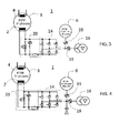
- Fig. 2 shows a block diagram of a generator system 1 similar to Fig. 1 .
- the excitation transformer 16 is designed with two star connections and is connected to the main excitation unit 15, with each branch of the thyristor bridge of the main excitation unit 15.
- a second exciter device 6 next to a first exciter device 4 is connected to the generator 3 and to the ceiling excitation unit 18.
- the first exciter device 4 is commonly fed by the electrical grid, the field winding 2 is excited by a voltage. Therefore, the excitation of the generator system 1 is stable while the electrical grid provides a stable voltage.
- the excitation transformer 16 is connected to the first exciter device 4 (not shown).
- the excitation transformer 16 controls the generator 3 via the main excitation unit 15.
- the ceiling excitation unit 18 is not active, the left switch 17 closing the electric circuit of the second exciter device 6 and the generator 3 is open.
- the second exciter device 6 which is an excitation generator in this example, is running and generating electrical power but is not connected with the generator 3.
- the second exciter device 6 can be realized with an output power of approximately 30kW. Further output powers of the second exciter device 6 suitable to excite the generator 3 can be provided. Then, the field winding 2 of the generator 3 is not excited by the second exciter device 6.
- the second exciter device 6 In common operation mode, without an electric grid failure and interruptions, the second exciter device 6 is permanently turned on and providing electrical energy.
- the field excitation of the generator 3 to be operated on the electric grid however is created by the first exciter device 4 in a common way of the state of the art, usually the voltage of the first exciter device is provided by the electrical grid.
- the first exciter device 4 provides the voltage for the field winding 2 as long as the electrical grid is not interrupted and the main excitation unit 18 is connected to the generator 3.
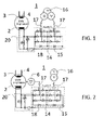
- Fig. 3 shows a block diagram of a circuit arrangement of a further example of the generator system 1.
- the excitation unit 14 is not separated in a main and ceiling excitation unit.
- the de-excitation unit 20 is identical to the de-excitation unit 20 of Figs. 1 and 2 .
- the second exciter device 6 is designed as a synchronous motor with three phases.
- the second exciter device 6 is connected to the excitation unit 14 and the excitation transformer 16 via two reverse connected thyristors, a thyristor circuit 19.
- the excitation transformer 16 is connected to the excitation unit 14 via two reverse connected thyristors, a thyristor circuit 19, in this example instead of a switch 17.
- the second exciter device 6 is in continuous operation, both in regular operation and in interrupted operation of the first exciter device 4 exciting the generator 3.
- the thyristor circuits 19 are fired and as a result the second exciter device 6 is connected to the field winding 2 of the generator 3.
- the thyristor circuit 19 connecting the second exciter device 6 with the generator 3 opens the connection and the thyristor circuit 19 connecting the first exciter device 4 via the excitation transformer 16 with the generator 3 is closed.
- the second exciter device 6 excites the field winding 2 instead of the first exciter device 4.
- This operation mode of excitation by the second exciter device 6 is maintained as long as there are interruptions in the electrical grid from which the generator 3 is supplied in common operation mode.
- Fig. 4 shows a block diagram of a circuit arrangement of a generator system 1 similar to Fig. 3 .
- the second exciter unit 6 is realized as an asynchronous motor with three phases, namely an asynchronous three phase booster instead of a synchronous booster.
- a capacity connected in series with a diode is connected to the second exciter device 6 and to the excitation transformer 16.
- the second exciter device 6 operates a unipolar generator with a voltage of approximately 0.8 kV and a direct current (DC) of approximately 6 kA to excite the generator 3.
- the asynchronous motor according to the example of Fig. 4 is then designed as a low power motor to drive the unipolar generator.
- the electrical grid failures occur only for a short time, so the second exciter device 6 operates only for short time durations.
- a unipolar generator is capable of providing a high power in relation to the motor driving the unipolar generator for a short time, so this configuration is particularly useful for the generator system 1 to reduce the energy consumption of the generator system 1.
- the second exciter device 6 can comprise a flywheel for storing mechanical energy.
- the flywheel is driven by a motor, in Fig. 4 an asynchronous motor, and during operation of the generator 3 the flywheel rotates, which means a mechanical energy is stored and can be used in case it is needed. The need for this stored energy arises again in case of a malfunction of the generator 3.
- the flywheel can be manufactured from steel or carbon fibre, especially from carbon nano fibre.
- the flywheel can be housed in a near vacuum environment to increase the efficiency, i.e. reduce the power to move the flywheel.
- the near vacuum is provided by a proper vacuum pump.
- the flywheel can be manufactured with a magnetic bearing which is here advantageous because little bearing maintenance is needed.
- the rotating flywheel is levitated through the force of a magnetic field, both a permanent magnetic field and a controlled magnetic field generated by electromagnets for the adjustment and centering of the bearing. This is useful for the long-term operation of a generator 3 in a power plant and the corresponding long-term operation of the second exciter device 6.
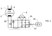
- Fig. 5 shows a block diagram of a circuit arrangement of a generator system 1 according to another example of the invention.
- the excitation transformer 16 is connected to the excitation unit 14 via a switch 17.
- the second exciter device 6 is designed as a direct current motor (DCM), a DC motor booster.
- the second exciter device 6 is connected to the de-excitation unit 20 and to the excitation unit 14. Similar to the previous examples of the invention the second exciter device 6 takes over the excitation of the field winding 2 of the generator 3 only in exceptional cases when the first exciter device 4 fails. In this case the excitation transformer 16 switches the generator 3 from the first exciter device 4 to the second exciter device 6.
- DCM direct current motor
- An inverter or converter can be connected with the second exciter device 6 to invert the voltage or convert the voltage into direct current (DC) voltage for specific applications of the invention.
- the use of an inverter with the generator system 1 enables the use of any motor in the second exciter device 6 independent from voltage or phase outputs of the motor.
- the output of the second exciter device 6 is adjusted to the requirements of the field winding 2 of the generator 3 with this means.
- the second exciter device 6 can comprise a pump in another example.
- the pump is suitable for storing mechanical energy.
- the mechanical energy of the pump In the regular operation mode of the generator 3 the mechanical energy of the pump is kept on a near constant level except for losses, no energy is discharged to the generator 3 then.
- the mechanical energy of the pump In malfunction mode of the generator 3 the mechanical energy of the pump is released, the mechanical energy is then converted into electrical energy by a further generator connected to the field winding 2 to excite the field winding 2.
- the stored mechanical energy of the pump is used to excite the generator 3 instead of the first exciter device 4.
- the task of the pump as a storage device is to keep the excitation current of the field winding 2 upright and safeguard the interruption-free running of the generator 3 which is of high importance for energy supply to the public grid.
- a part of the energy generated in the second exciter device 6 can be branched off to supply energy to other critical components of the power plant in case of malfunction, as lube pumps, monitoring devices of the power plant,
Landscapes
- Engineering & Computer Science (AREA)
- Power Engineering (AREA)
- Control Of Eletrric Generators (AREA)
Priority Applications (2)
| Application Number | Priority Date | Filing Date | Title |
|---|---|---|---|
| EP14188293.6A EP2911292B1 (de) | 2014-10-09 | 2014-10-09 | Verfahren und Generatorsystem zum Betrieb eines Generators |
| US14/872,656 US9634595B2 (en) | 2014-10-09 | 2015-10-01 | Method and a generator system for operating a generator |
Applications Claiming Priority (1)
| Application Number | Priority Date | Filing Date | Title |
|---|---|---|---|
| EP14188293.6A EP2911292B1 (de) | 2014-10-09 | 2014-10-09 | Verfahren und Generatorsystem zum Betrieb eines Generators |
Publications (2)
| Publication Number | Publication Date |
|---|---|
| EP2911292A1 true EP2911292A1 (de) | 2015-08-26 |
| EP2911292B1 EP2911292B1 (de) | 2018-03-07 |
Family
ID=51661997
Family Applications (1)
| Application Number | Title | Priority Date | Filing Date |
|---|---|---|---|
| EP14188293.6A Not-in-force EP2911292B1 (de) | 2014-10-09 | 2014-10-09 | Verfahren und Generatorsystem zum Betrieb eines Generators |
Country Status (2)
| Country | Link |
|---|---|
| US (1) | US9634595B2 (de) |
| EP (1) | EP2911292B1 (de) |
Cited By (1)
| Publication number | Priority date | Publication date | Assignee | Title |
|---|---|---|---|---|
| RU168545U1 (ru) * | 2016-07-20 | 2017-02-08 | Общество с ограниченной ответственностью Научно-производственное предприятие "ЭКРА" | Статический возбудитель синхронного двигателя |
Families Citing this family (1)
| Publication number | Priority date | Publication date | Assignee | Title |
|---|---|---|---|---|
| US11329539B2 (en) | 2020-03-11 | 2022-05-10 | Hamilton Sundstrand Corporation | Controller for a generator |
Citations (5)
| Publication number | Priority date | Publication date | Assignee | Title |
|---|---|---|---|---|
| EP0122310A1 (de) * | 1983-04-15 | 1984-10-24 | Hokuetsu Industries Co., Ltd. | Steuereinrichtung für einen selbsterregten Drehstromgenerator |
| US5404091A (en) * | 1993-05-27 | 1995-04-04 | General Electric Company | Switched reluctance generator system with self-excitation capability during load faults |
| US20070296275A1 (en) | 2004-10-28 | 2007-12-27 | Reinhard Joho | Static Exciter System for a Generator and Method of Operation |
| EP2288017A1 (de) * | 2009-07-30 | 2011-02-23 | Alstom Technology Ltd | Statischer Erreger einer Feldwicklung und ein Verfahren, um diese zu betreiben |
| EP2293432A1 (de) * | 2009-09-07 | 2011-03-09 | Alstom Technology Ltd | Statischer Erreger eines elektrischen Generators, Verfahren zum Nachrüsten und Betriebsverfahren dafür |
Family Cites Families (16)
| Publication number | Priority date | Publication date | Assignee | Title |
|---|---|---|---|---|
| US4743777A (en) * | 1986-03-07 | 1988-05-10 | Westinghouse Electric Corp. | Starter generator system with two stator exciter windings |
| US4939441A (en) * | 1989-10-27 | 1990-07-03 | Sundstrand Corporation | Excitation system for a brushless generator having separate AC and DC exciter field windings |
| US5097195A (en) * | 1989-11-27 | 1992-03-17 | Sundstrand Corporation | AC exciter for VSCF starter/generator |
| US5068590A (en) * | 1989-12-20 | 1991-11-26 | Sundstrand Corporation | Brushless generator having AC excitation in generating and starting modes |
| US5289107A (en) * | 1992-03-30 | 1994-02-22 | General Electric Company | Switched reluctance generator system with fault recovery capability |
| US5283471A (en) * | 1992-08-31 | 1994-02-01 | Eemco/Datron, Inc. | DC generator and back-up engine starting apparatus |
| US5493200A (en) * | 1993-05-12 | 1996-02-20 | Sundstrand Corporation | Control for a brushless generator |
| US5430362A (en) * | 1993-05-12 | 1995-07-04 | Sundstrand Corporation | Engine starting system utilizing multiple controlled acceleration rates |
| US5444349A (en) * | 1993-05-12 | 1995-08-22 | Sundstrand Corporation | Starting control for an electromagnetic machine |
| US5594322A (en) * | 1993-05-12 | 1997-01-14 | Sundstrand Corporation | Starter/generator system with variable-frequency exciter control |
| US5747971A (en) * | 1996-08-08 | 1998-05-05 | Sundstrand Corporation | Position and velocity sensorless control for a motor generator system operated as a motor using exciter impedance |
| US6844707B1 (en) * | 2003-12-30 | 2005-01-18 | Pacific Scientific/Electro Kinetics Division | AC/DC brushless starter-generator |
| US7508086B2 (en) * | 2006-03-24 | 2009-03-24 | General Electric Company | Aircraft engine starter/generator and controller |
| US8319481B2 (en) * | 2006-12-26 | 2012-11-27 | Hamilton Sundstrand Corporation | Pole shifting generator |
| US8928293B1 (en) * | 2013-08-02 | 2015-01-06 | Hamilton Sundstrand Corporation | Systems for wound field synchronous machines with zero speed rotor position detection during start for motoring and improved transient response for generation |
| US9508479B1 (en) * | 2015-06-19 | 2016-11-29 | General Electric Company | Method for in-situ magnetization or degaussing of generator rotor |
-
2014
- 2014-10-09 EP EP14188293.6A patent/EP2911292B1/de not_active Not-in-force
-
2015
- 2015-10-01 US US14/872,656 patent/US9634595B2/en not_active Expired - Fee Related
Patent Citations (6)
| Publication number | Priority date | Publication date | Assignee | Title |
|---|---|---|---|---|
| EP0122310A1 (de) * | 1983-04-15 | 1984-10-24 | Hokuetsu Industries Co., Ltd. | Steuereinrichtung für einen selbsterregten Drehstromgenerator |
| US5404091A (en) * | 1993-05-27 | 1995-04-04 | General Electric Company | Switched reluctance generator system with self-excitation capability during load faults |
| US20070296275A1 (en) | 2004-10-28 | 2007-12-27 | Reinhard Joho | Static Exciter System for a Generator and Method of Operation |
| EP2288017A1 (de) * | 2009-07-30 | 2011-02-23 | Alstom Technology Ltd | Statischer Erreger einer Feldwicklung und ein Verfahren, um diese zu betreiben |
| EP2288017B1 (de) | 2009-07-30 | 2012-11-14 | Alstom Technology Ltd | Statischer Erreger einer Feldwicklung und ein Verfahren, um diese zu betreiben |
| EP2293432A1 (de) * | 2009-09-07 | 2011-03-09 | Alstom Technology Ltd | Statischer Erreger eines elektrischen Generators, Verfahren zum Nachrüsten und Betriebsverfahren dafür |
Cited By (1)
| Publication number | Priority date | Publication date | Assignee | Title |
|---|---|---|---|---|
| RU168545U1 (ru) * | 2016-07-20 | 2017-02-08 | Общество с ограниченной ответственностью Научно-производственное предприятие "ЭКРА" | Статический возбудитель синхронного двигателя |
Also Published As
| Publication number | Publication date |
|---|---|
| EP2911292B1 (de) | 2018-03-07 |
| US9634595B2 (en) | 2017-04-25 |
| US20160105136A1 (en) | 2016-04-14 |
Similar Documents
| Publication | Publication Date | Title |
|---|---|---|
| US6819012B1 (en) | Flywheel energy storage system | |
| US6462429B1 (en) | Induction motor/generator system | |
| KR100705864B1 (ko) | 터빈 작동 방법, 터빈 시동 방법 및 전력 회로 | |
| US6486627B1 (en) | Flywheel uninterruptible power source | |
| EP2940860B1 (de) | Generator zur Erzeugung von elektrischem Strom | |
| EP1928080B2 (de) | Anregungsspannungsversorgung für synchronen Erzeuger von einer Windturbine und Verfahren zum Starten einer Windturbine mit einer solchen Anregungsspannungsversorgung | |
| US8723358B2 (en) | Line interactive power quality system | |
| US6788029B1 (en) | Flywheel with switched coupling regulator | |
| RU2743307C1 (ru) | Способ снабжения энергией компонентов ветроэнергетической установки, а также устройство энергоснабжения и ветроэнергетическая установка с таким устройством | |
| CN104040171A (zh) | 风力发电系统 | |
| JP2015511108A (ja) | 揚水発電所用電気ユニットの動作方法 | |
| WO2019125723A1 (en) | System and method for modulating high power in a submersible energy storage vessel utilizing high voltage dc transmission | |
| WO2014193238A1 (en) | Fault tolerant power supply for active magnetic bearing | |
| JP5331662B2 (ja) | 自然エネルギーによって発電された電力の変換装置 | |
| US10855215B2 (en) | Power generation system technical field | |
| JP2016015824A (ja) | 交流励磁機の励磁装置 | |
| US9634595B2 (en) | Method and a generator system for operating a generator | |
| GB2559949A (en) | Power grid stabilising system | |
| US10734931B2 (en) | Brushless synchronous power generation apparatus | |
| US20100321968A1 (en) | Load fault handling for switched reluctance or induction type machines | |
| CN105207334B (zh) | 用于向负载供应电力的系统以及对应电力供应方法 | |
| EP2911288A1 (de) | Fremderregte Synchronmaschine mit aus dem Gleichspannungszwischenkreis des Statorumrichters versorgter Erregung | |
| EP3076515B1 (de) | Stromversorgungssystem | |
| JP2011050167A (ja) | 二次励磁型発電システム | |
| EP2912765B1 (de) | Dynamoelektrische maschine |
Legal Events
| Date | Code | Title | Description |
|---|---|---|---|
| PUAI | Public reference made under article 153(3) epc to a published international application that has entered the european phase |
Free format text: ORIGINAL CODE: 0009012 |
|
| AK | Designated contracting states |
Kind code of ref document: A1 Designated state(s): AL AT BE BG CH CY CZ DE DK EE ES FI FR GB GR HR HU IE IS IT LI LT LU LV MC MK MT NL NO PL PT RO RS SE SI SK SM TR |
|
| AX | Request for extension of the european patent |
Extension state: BA ME |
|
| 17P | Request for examination filed |
Effective date: 20160211 |
|
| RBV | Designated contracting states (corrected) |
Designated state(s): AL AT BE BG CH CY CZ DE DK EE ES FI FR GB GR HR HU IE IS IT LI LT LU LV MC MK MT NL NO PL PT RO RS SE SI SK SM TR |
|
| RAP1 | Party data changed (applicant data changed or rights of an application transferred) |
Owner name: GENERAL ELECTRIC TECHNOLOGY GMBH |
|
| 17Q | First examination report despatched |
Effective date: 20170316 |
|
| GRAP | Despatch of communication of intention to grant a patent |
Free format text: ORIGINAL CODE: EPIDOSNIGR1 |
|
| INTG | Intention to grant announced |
Effective date: 20171020 |
|
| GRAS | Grant fee paid |
Free format text: ORIGINAL CODE: EPIDOSNIGR3 |
|
| GRAA | (expected) grant |
Free format text: ORIGINAL CODE: 0009210 |
|
| AK | Designated contracting states |
Kind code of ref document: B1 Designated state(s): AL AT BE BG CH CY CZ DE DK EE ES FI FR GB GR HR HU IE IS IT LI LT LU LV MC MK MT NL NO PL PT RO RS SE SI SK SM TR |
|
| REG | Reference to a national code |
Ref country code: GB Ref legal event code: FG4D |
|
| REG | Reference to a national code |
Ref country code: CH Ref legal event code: EP Ref country code: AT Ref legal event code: REF Ref document number: 977569 Country of ref document: AT Kind code of ref document: T Effective date: 20180315 |
|
| REG | Reference to a national code |
Ref country code: IE Ref legal event code: FG4D |
|
| REG | Reference to a national code |
Ref country code: DE Ref legal event code: R096 Ref document number: 602014021905 Country of ref document: DE |
|
| REG | Reference to a national code |
Ref country code: NL Ref legal event code: MP Effective date: 20180307 |
|
| REG | Reference to a national code |
Ref country code: LT Ref legal event code: MG4D |
|
| PG25 | Lapsed in a contracting state [announced via postgrant information from national office to epo] |
Ref country code: FI Free format text: LAPSE BECAUSE OF FAILURE TO SUBMIT A TRANSLATION OF THE DESCRIPTION OR TO PAY THE FEE WITHIN THE PRESCRIBED TIME-LIMIT Effective date: 20180307 Ref country code: LT Free format text: LAPSE BECAUSE OF FAILURE TO SUBMIT A TRANSLATION OF THE DESCRIPTION OR TO PAY THE FEE WITHIN THE PRESCRIBED TIME-LIMIT Effective date: 20180307 Ref country code: CY Free format text: LAPSE BECAUSE OF FAILURE TO SUBMIT A TRANSLATION OF THE DESCRIPTION OR TO PAY THE FEE WITHIN THE PRESCRIBED TIME-LIMIT Effective date: 20180307 Ref country code: ES Free format text: LAPSE BECAUSE OF FAILURE TO SUBMIT A TRANSLATION OF THE DESCRIPTION OR TO PAY THE FEE WITHIN THE PRESCRIBED TIME-LIMIT Effective date: 20180307 Ref country code: HR Free format text: LAPSE BECAUSE OF FAILURE TO SUBMIT A TRANSLATION OF THE DESCRIPTION OR TO PAY THE FEE WITHIN THE PRESCRIBED TIME-LIMIT Effective date: 20180307 Ref country code: NO Free format text: LAPSE BECAUSE OF FAILURE TO SUBMIT A TRANSLATION OF THE DESCRIPTION OR TO PAY THE FEE WITHIN THE PRESCRIBED TIME-LIMIT Effective date: 20180607 |
|
| REG | Reference to a national code |
Ref country code: AT Ref legal event code: MK05 Ref document number: 977569 Country of ref document: AT Kind code of ref document: T Effective date: 20180307 |
|
| PG25 | Lapsed in a contracting state [announced via postgrant information from national office to epo] |
Ref country code: RS Free format text: LAPSE BECAUSE OF FAILURE TO SUBMIT A TRANSLATION OF THE DESCRIPTION OR TO PAY THE FEE WITHIN THE PRESCRIBED TIME-LIMIT Effective date: 20180307 Ref country code: BG Free format text: LAPSE BECAUSE OF FAILURE TO SUBMIT A TRANSLATION OF THE DESCRIPTION OR TO PAY THE FEE WITHIN THE PRESCRIBED TIME-LIMIT Effective date: 20180607 Ref country code: GR Free format text: LAPSE BECAUSE OF FAILURE TO SUBMIT A TRANSLATION OF THE DESCRIPTION OR TO PAY THE FEE WITHIN THE PRESCRIBED TIME-LIMIT Effective date: 20180608 Ref country code: SE Free format text: LAPSE BECAUSE OF FAILURE TO SUBMIT A TRANSLATION OF THE DESCRIPTION OR TO PAY THE FEE WITHIN THE PRESCRIBED TIME-LIMIT Effective date: 20180307 Ref country code: LV Free format text: LAPSE BECAUSE OF FAILURE TO SUBMIT A TRANSLATION OF THE DESCRIPTION OR TO PAY THE FEE WITHIN THE PRESCRIBED TIME-LIMIT Effective date: 20180307 |
|
| PG25 | Lapsed in a contracting state [announced via postgrant information from national office to epo] |
Ref country code: NL Free format text: LAPSE BECAUSE OF FAILURE TO SUBMIT A TRANSLATION OF THE DESCRIPTION OR TO PAY THE FEE WITHIN THE PRESCRIBED TIME-LIMIT Effective date: 20180307 Ref country code: AL Free format text: LAPSE BECAUSE OF FAILURE TO SUBMIT A TRANSLATION OF THE DESCRIPTION OR TO PAY THE FEE WITHIN THE PRESCRIBED TIME-LIMIT Effective date: 20180307 Ref country code: PL Free format text: LAPSE BECAUSE OF FAILURE TO SUBMIT A TRANSLATION OF THE DESCRIPTION OR TO PAY THE FEE WITHIN THE PRESCRIBED TIME-LIMIT Effective date: 20180307 Ref country code: RO Free format text: LAPSE BECAUSE OF FAILURE TO SUBMIT A TRANSLATION OF THE DESCRIPTION OR TO PAY THE FEE WITHIN THE PRESCRIBED TIME-LIMIT Effective date: 20180307 Ref country code: EE Free format text: LAPSE BECAUSE OF FAILURE TO SUBMIT A TRANSLATION OF THE DESCRIPTION OR TO PAY THE FEE WITHIN THE PRESCRIBED TIME-LIMIT Effective date: 20180307 |
|
| PG25 | Lapsed in a contracting state [announced via postgrant information from national office to epo] |
Ref country code: CZ Free format text: LAPSE BECAUSE OF FAILURE TO SUBMIT A TRANSLATION OF THE DESCRIPTION OR TO PAY THE FEE WITHIN THE PRESCRIBED TIME-LIMIT Effective date: 20180307 Ref country code: SK Free format text: LAPSE BECAUSE OF FAILURE TO SUBMIT A TRANSLATION OF THE DESCRIPTION OR TO PAY THE FEE WITHIN THE PRESCRIBED TIME-LIMIT Effective date: 20180307 Ref country code: SM Free format text: LAPSE BECAUSE OF FAILURE TO SUBMIT A TRANSLATION OF THE DESCRIPTION OR TO PAY THE FEE WITHIN THE PRESCRIBED TIME-LIMIT Effective date: 20180307 Ref country code: AT Free format text: LAPSE BECAUSE OF FAILURE TO SUBMIT A TRANSLATION OF THE DESCRIPTION OR TO PAY THE FEE WITHIN THE PRESCRIBED TIME-LIMIT Effective date: 20180307 |
|
| REG | Reference to a national code |
Ref country code: DE Ref legal event code: R097 Ref document number: 602014021905 Country of ref document: DE |
|
| PG25 | Lapsed in a contracting state [announced via postgrant information from national office to epo] |
Ref country code: PT Free format text: LAPSE BECAUSE OF FAILURE TO SUBMIT A TRANSLATION OF THE DESCRIPTION OR TO PAY THE FEE WITHIN THE PRESCRIBED TIME-LIMIT Effective date: 20180709 |
|
| PLBE | No opposition filed within time limit |
Free format text: ORIGINAL CODE: 0009261 |
|
| STAA | Information on the status of an ep patent application or granted ep patent |
Free format text: STATUS: NO OPPOSITION FILED WITHIN TIME LIMIT |
|
| PG25 | Lapsed in a contracting state [announced via postgrant information from national office to epo] |
Ref country code: DK Free format text: LAPSE BECAUSE OF FAILURE TO SUBMIT A TRANSLATION OF THE DESCRIPTION OR TO PAY THE FEE WITHIN THE PRESCRIBED TIME-LIMIT Effective date: 20180307 |
|
| 26N | No opposition filed |
Effective date: 20181210 |
|
| PG25 | Lapsed in a contracting state [announced via postgrant information from national office to epo] |
Ref country code: SI Free format text: LAPSE BECAUSE OF FAILURE TO SUBMIT A TRANSLATION OF THE DESCRIPTION OR TO PAY THE FEE WITHIN THE PRESCRIBED TIME-LIMIT Effective date: 20180307 |
|
| REG | Reference to a national code |
Ref country code: CH Ref legal event code: PL |
|
| GBPC | Gb: european patent ceased through non-payment of renewal fee |
Effective date: 20181009 |
|
| REG | Reference to a national code |
Ref country code: BE Ref legal event code: MM Effective date: 20181031 |
|
| PG25 | Lapsed in a contracting state [announced via postgrant information from national office to epo] |
Ref country code: LU Free format text: LAPSE BECAUSE OF NON-PAYMENT OF DUE FEES Effective date: 20181009 Ref country code: MC Free format text: LAPSE BECAUSE OF FAILURE TO SUBMIT A TRANSLATION OF THE DESCRIPTION OR TO PAY THE FEE WITHIN THE PRESCRIBED TIME-LIMIT Effective date: 20180307 |
|
| REG | Reference to a national code |
Ref country code: IE Ref legal event code: MM4A |
|
| PG25 | Lapsed in a contracting state [announced via postgrant information from national office to epo] |
Ref country code: CH Free format text: LAPSE BECAUSE OF NON-PAYMENT OF DUE FEES Effective date: 20181031 Ref country code: BE Free format text: LAPSE BECAUSE OF NON-PAYMENT OF DUE FEES Effective date: 20181031 Ref country code: LI Free format text: LAPSE BECAUSE OF NON-PAYMENT OF DUE FEES Effective date: 20181031 Ref country code: FR Free format text: LAPSE BECAUSE OF NON-PAYMENT OF DUE FEES Effective date: 20181031 |
|
| PG25 | Lapsed in a contracting state [announced via postgrant information from national office to epo] |
Ref country code: IE Free format text: LAPSE BECAUSE OF NON-PAYMENT OF DUE FEES Effective date: 20181009 Ref country code: GB Free format text: LAPSE BECAUSE OF NON-PAYMENT OF DUE FEES Effective date: 20181009 |
|
| PGFP | Annual fee paid to national office [announced via postgrant information from national office to epo] |
Ref country code: IT Payment date: 20190918 Year of fee payment: 6 |
|
| PG25 | Lapsed in a contracting state [announced via postgrant information from national office to epo] |
Ref country code: MT Free format text: LAPSE BECAUSE OF NON-PAYMENT OF DUE FEES Effective date: 20181009 |
|
| PG25 | Lapsed in a contracting state [announced via postgrant information from national office to epo] |
Ref country code: TR Free format text: LAPSE BECAUSE OF FAILURE TO SUBMIT A TRANSLATION OF THE DESCRIPTION OR TO PAY THE FEE WITHIN THE PRESCRIBED TIME-LIMIT Effective date: 20180307 |
|
| PG25 | Lapsed in a contracting state [announced via postgrant information from national office to epo] |
Ref country code: MK Free format text: LAPSE BECAUSE OF NON-PAYMENT OF DUE FEES Effective date: 20180307 Ref country code: HU Free format text: LAPSE BECAUSE OF FAILURE TO SUBMIT A TRANSLATION OF THE DESCRIPTION OR TO PAY THE FEE WITHIN THE PRESCRIBED TIME-LIMIT; INVALID AB INITIO Effective date: 20141009 |
|
| PG25 | Lapsed in a contracting state [announced via postgrant information from national office to epo] |
Ref country code: IS Free format text: LAPSE BECAUSE OF FAILURE TO SUBMIT A TRANSLATION OF THE DESCRIPTION OR TO PAY THE FEE WITHIN THE PRESCRIBED TIME-LIMIT Effective date: 20180707 |
|
| PG25 | Lapsed in a contracting state [announced via postgrant information from national office to epo] |
Ref country code: IT Free format text: LAPSE BECAUSE OF NON-PAYMENT OF DUE FEES Effective date: 20201009 |
|
| PGFP | Annual fee paid to national office [announced via postgrant information from national office to epo] |
Ref country code: DE Payment date: 20230920 Year of fee payment: 10 |
|
| REG | Reference to a national code |
Ref country code: DE Ref legal event code: R119 Ref document number: 602014021905 Country of ref document: DE |
|
| PG25 | Lapsed in a contracting state [announced via postgrant information from national office to epo] |
Ref country code: DE Free format text: LAPSE BECAUSE OF NON-PAYMENT OF DUE FEES Effective date: 20250501 |