EP2911341B1 - Procédé et dispositif de commutation dynamique d'une passerelle d'interconnexion de réseau distribué résilient (drni) - Google Patents
Procédé et dispositif de commutation dynamique d'une passerelle d'interconnexion de réseau distribué résilient (drni) Download PDFInfo
- Publication number
- EP2911341B1 EP2911341B1 EP13847852.4A EP13847852A EP2911341B1 EP 2911341 B1 EP2911341 B1 EP 2911341B1 EP 13847852 A EP13847852 A EP 13847852A EP 2911341 B1 EP2911341 B1 EP 2911341B1
- Authority
- EP
- European Patent Office
- Prior art keywords
- gateway
- portal system
- main
- backup
- information
- Prior art date
- Legal status (The legal status is an assumption and is not a legal conclusion. Google has not performed a legal analysis and makes no representation as to the accuracy of the status listed.)
- Active
Links
Images





Classifications
-
- H—ELECTRICITY
- H04—ELECTRIC COMMUNICATION TECHNIQUE
- H04L—TRANSMISSION OF DIGITAL INFORMATION, e.g. TELEGRAPHIC COMMUNICATION
- H04L45/00—Routing or path finding of packets in data switching networks
- H04L45/28—Routing or path finding of packets in data switching networks using route fault recovery
-
- H—ELECTRICITY
- H04—ELECTRIC COMMUNICATION TECHNIQUE
- H04L—TRANSMISSION OF DIGITAL INFORMATION, e.g. TELEGRAPHIC COMMUNICATION
- H04L45/00—Routing or path finding of packets in data switching networks
-
- H—ELECTRICITY
- H04—ELECTRIC COMMUNICATION TECHNIQUE
- H04L—TRANSMISSION OF DIGITAL INFORMATION, e.g. TELEGRAPHIC COMMUNICATION
- H04L45/00—Routing or path finding of packets in data switching networks
- H04L45/24—Multipath
- H04L45/245—Link aggregation, e.g. trunking
-
- H—ELECTRICITY
- H04—ELECTRIC COMMUNICATION TECHNIQUE
- H04L—TRANSMISSION OF DIGITAL INFORMATION, e.g. TELEGRAPHIC COMMUNICATION
- H04L47/00—Traffic control in data switching networks
- H04L47/10—Flow control; Congestion control
- H04L47/41—Flow control; Congestion control by acting on aggregated flows or links
Definitions
- the present invention relates to the network communication protection technology, and in particular, to a method and apparatus for dynamically switching a gateway in distributed resilient network interconnect (DRNI).
- DRNI distributed resilient network interconnect
- the interconnection among the networks is used more and more, to bear more services.
- the protection can be realized by adopting the port aggregation or loop mode.
- the loop network protection technology is limited by the network topology, and it is not applicable to adopting the whole network connection mode for the network interconnection part.
- the link aggregation can realize the protection of multiple links, but only limited to the link aggregation supporting the single node, which cannot satisfy the demand of the node protection.
- the IEEE standard organization proposes the DRNI technology, to support the link aggregation of the multiple nodes.
- one or more portal systems constitute one logical end point to perform the link aggregation, and the multiple links of the multiple portal systems are aggregated into one distributed Link Aggregation Group (LAG), thus guaranteeing the double protection of the link and node in the network interconnection area.
- LAG distributed Link Aggregation Group
- the DRNI adopts the distribution mode according to the service message, and appoints one portal system in which the gateway is located for each service.
- the service of the present network will be sent to the opposite-end network, or the service of the opposite-end network will enter the present network, they will all need to be filtered through the gateway first, and only the service message which is not abandoned by the gateway will be forwarded.
- the standard does not define the problem how to guarantee realizing the service retransmission through redistributing the service gateway when the portal system in which the gateway is located breaks down or is removed.
- the links among the portal systems A, B and C of the end point 1 in network 1 and the portal systems D and E of the end point 2 in network 2 are aggregated as one distributed aggregation group.
- the gateway of the services 1-200 is appointed in the portal system A.
- the service flow of the services 1-200 is forwarded to the portal system A; because the gateway of the portal system A is the gateway of the services 1-200, then the service is sent to the network 2 through the portal system A.
- the portal system breaks down or the interconnection link breaks down, the portal system is caused to be removed from the aggregation group, the gateway in the portal system influenced by the fault is required to be transferred to other portal systems, otherwise, it will cause the service cutoff.
- the portal system A breaks down, after the service flow of the services 1-200 is sent to the portal system A, the portal system A abandons the service, and it is unable to forward the service flow to the network 1, which causes the flowrate cutoff.
- the first portal system as the portal system in which the main gateway of a certain service is located
- the second portal system as the portal system in which the backup gateway is located in the end points of the aggregation group.
- the problem how to switch the gateway when the portal system in which the main gateway is located is removed from the aggregation group caused by the fault of interconnection link is not considered. Meanwhile, for the situation that the end points of the distributed aggregation group are composed of at least 2 portal systems, if there is a portal system removed from the aggregation group, the main and backup gateways are required to be reappointed, otherwise, the dynamic switchover of the gateway cannot be realized.
- the publication XP 011205402 discloses a method for switching a gateway of distributed resilient network interconnect comprising an end-to-end pseudowire redundancy mechanism.
- the embodiment of the present invention provides a method and apparatus for dynamically switching a gateway of DRNI, to solve the problem that the gateway of the DRNI in the system is unable to be switched dynamically.
- the embodiment of the present invention provides a method for dynamically switching a gateway of distributed resilient network interconnect (DRNI), comprising:
- the event comprises but not limited to one of the follows:
- the new main and backup gateways of the service or session are determined according to obtained information of the main and backup gateways.
- synchronizing the information of the main and backup gateways of each portal system between the portal system of the DRNI end point and other portal systems of the present end point comprises:
- the information of the main and backup gateways is synchronized through a way that a distributed relay control protocol (DRCP) message carries a type length value (TLV).
- DRCP distributed relay control protocol
- TLV type length value
- the embodiment of the present invention further provides an apparatus for dynamically switching a gateway of distributed resilient network interconnect (DRNI), applied in a portal system, comprising:
- DRNI distributed resilient network interconnect
- the event comprises but not limited to one of the follows:
- the new main and backup gateways of the service or session are determined according to the information of the main and backup gateways.
- the information synchronization module is configured to: synchronize the information of the main and backup gateways of each portal system with other portal systems of the present end point in a following way:
- the information of the main and backup gateways is synchronized through a way that a distributed relay control protocol (DRCP) message carries a type length value (TLV).
- DRCP distributed relay control protocol
- TLV type length value
- each portal system synchronizes the information of the main and backup gateways in real time.
- the portal system in which the gateway is located breaks down or the portal system in which the gateway is located is removed from the aggregation group, there is no need to reappoint the main and backup gateways. It can just realize switching the gateway of the service or session dynamically and enable the service or the session to be transmitted from another portal system in the aggregation group.
- the method embodiment for dynamically switching a gateway of distributed resilient network interconnect (DRNI) in the present invention is as shown in FIG. 3 and includes the following steps.
- step 301 information synchronization is performed, and information of main and backup gateways of each portal system is synchronized between a portal system of a DRNI end point and other portal systems of a present end point.
- the step 301 is performed when the system is initialized or the information of the main and backup gateways is changed.
- the information of the main and backup gateways is synchronized to other portal systems of the present end point through a way that the DRCP message carries the gateway information TLV among the portal systems of the end points in the aggregation group.
- the information of the main and backup gateways in the embodiment of the present invention is mainly used for enabling the portal system to be used for determining the portal system in which the main and backup gateways of the service or session are located, in order to realize the dynamic switchover smoothly.
- the information of the main and backup gateways includes the following information:
- the information of the main and backup gateways may be the synchronized information of the main and backup gateways, and also may be the coding information of gateway sequential list directly configured by the system), thus performing the dynamic switchover smoothly, which will not influence the normal forwarding of service or session.
- One portal system may send its gateway to all other portal systems as the information of the main and backup gateways of the main gateway, in order to realize the synchronization of its information, which also can be realized through forwarding to each other among the portal systems, to finally achieve the synchronization of the information of the main and backup gateways of all portal systems of the present end point.
- step 302 the detection of event is performed and the portal system detects whether an event which triggers switching the main and backup gateways occurs or not.
- step 303 the main and backup switchover is performed, and a gateway of a service or session is updated when the event which triggers switching the main and backup gateways is detected, and a portal system in which a new main gateway of the service or session is located starts to forward the service or session via the main gateway, and a portal system in which the backup gateway of the service or session is located stops forwarding the service or session via the backup gateway.
- the new main and backup gateways of the service or session are determined according to obtained information of the main and backup gateways.
- the gateway of the present portal system After determining the gateway of the portal system as the first-selected gateway of the service or session, the gateway of the present portal system is activated as the new main gateway of the service or session to forward the service or session, and the source node is notified that the gateway switchover occurs. Meanwhile, the information of the main and backup gateways of the service or session is updated, to trigger the information synchronization step 301.
- the portal system in which the new main gateway of the influenced service or session is located notifies the source node of the service or session that the gateway switchover occurs.
- the fault recovery which triggers switching the main and backup gateways, and it forwards the service or session taking its own gateway as the main gateway through the present gateway, and notifies the source node of the service or session that the gateway switchover occurs
- Other portal systems of the present end point receive the information of the main and backup gateways of the already recovered portal system, detecting the breakdown recovery, and obtain the service or session taking the gateway of the recovered portal system as the main gateway from the received information of the main and backup gateways.
- the gateway of the service or session in the present portal system is switched to the backup gateway, and the service or session is not forwarded through the present gateway. Meanwhile, the information of the main and backup gateways of the service or session is updated, and the gateway synchronization is performed.
- the updated information of the main and backup gateways is announced in real time to each other among the portal systems in the DRNI end point through the DRCP control protocol. If the main gateway breaks down or the portal system in which the main gateway is located is removed, the first-selected backup gateway takes over and becomes the main gateway, and the new backup gateway is selected, and the information of the main and backup gateways is updated. If the backup gateway breaks down, then the new backup gateway is selected, and the information of the main and backup gateways is updated.
- the TLV includes: a Portal System Priority field, representing the priority of the portal system.
- the Portal System field is the Media Access Control (MAC) address code of the portal system.
- the Portal System Priority and Portal System fields are used for identifying one portal system.
- the Service/Session List field represents the codes of a service or session sequence of the main gateway in the present portal system.
- the Backup gateway List field represents the backup gateway list code, and the Backup Priority appoints the priority of the gateway as the backup gateway in the portal system.
- the Select Algorithm field represents the service or session taking the gateway of the present portal system as the main gateway selects the method adopted by the backup gateway, and the value of the field is exampled as follows.
- Select Algorithm 01, representing that it is to select the gateway of the available portal system of which the value of Backup Priority is small (that is, the priority is high) in the Backup gateway List as the first-selected gateway of the Service List when the main gateway breaks down.
- the method is suitable for managing or appointing the system to directly obtain the priority sequence of the backup portal system of the service or session according to the algorithm.
- Select Algorithm 02, representing that it is to select the gateway of the portal system of which the value of Portal System Priority is small (that is, the portal system priority is high), except the main system, in the end points of the aggregation group as the first-selected gateway when the main gateway breaks down.
- Select Algorithm 03, representing that it is to perform the average distribution on the services or sessions according to the number of backup portal systems when the main gateway breaks down, and the service or the session with the large sequence number is distributed into the system with the high portal system priority.
- the backup portal system is the other portal system, except the portal system in which the main gateway is located, in the present end point.
- Select Algorithm 04, representing that it is to perform distribution according to a way of the services or sessions modulo the number of backup portal system when the main gateway breaks down, and the one with the large value of modulus is distributed into the portal system with the high portal system priority.
- the backup portal system is all other portal systems, except the portal system in which the main gateway is located, in the present end point.
- Select Algorithm 05, representing that the selected gateway of the service or session and the aggregation link forwarding the service or session are in the same portal system.
- the gateway of the portal system B is the gateway of the services 201-300
- the gateway of the portal system C is the gateway of the services 301-400
- the priority of the portal system A is 01
- the priority of the portal system B is 02
- the priority of the portal system C is 03, that is, the priorities of the portal systems from high to low are A, B and C.
- the method of realizing gateway dynamic switchover in the present application includes the following steps.
- step 701 the portal systems A, B and C announce the gateways to which they belong and the backup gateway select algorithm to each other through the DRCP control protocol.
- the gateway information announced among the portal systems is carried through the TLV.
- the gateway information TLV announced by the portal system A to the portal systems B and C is shown as FIG. 10(1) , representing that the portal system priority of the portal system A is 01; the MAC address code of the portal system is A; for the services with a service sequence being 1-100, the portal system with the high portal system priority is selected as the portal system in which the backup gateway is located; for the services, with the service sequence being 101-200, taking the gateway of the portal system A as the main gateway, the average distribution method is adopted to select the portal system in which the backup gateway is located.
- the gateway information TLV announced by the portal system B to the portal system A and C is shown as FIG. 10(2) , representing that the portal system priority of the portal system B is 02; the MAC address code of the portal system is B; for the services, with the service sequence being 201-300, taking the gateway of the portal system B as the main gateway, the portal system with the high portal system priority is selected as the portal system in which the backup gateway is located.
- the gateway information TLV announced by the portal system C to the portal system A and B is shown as FIG. 10(3) , representing that the portal system priority of the portal system C is 03; the MAC address code of the portal system is C; for the services, with the service sequence being 301-400, taking the gateway of the portal system C as the main gateway, the portal system with the high portal system priority is selected as the portal system in which the backup gateway is located.
- the portal system after receiving the gateway information of the other portal systems, carries the received gateway information of other portal systems in the TLV for the mutual announcement as well, as shown in FIG. 5 , that is, including, the priority of the present portal system, the address identifier and the gateway information, and the priority, address identifier and gateway information of other portal systems, and finally the synchronization of gateway information is achieved.
- the portal systems A, B and C judge that the portal system priorities from high to low are A, B and C according to the priority of each portal system obtained from the gateway information TLV.
- step 702 the portal systems A, B and C detect that the event which triggers switching the main and backup gateways occurs.
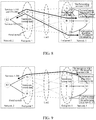
- the portal system A breaks down (as shown in FIG. 7 ), or the interconnection link breaks down, causing the portal system A to be isolated (as shown in FIG. 8 ), or the portal system A is made to be removed from the aggregation group due to the configuration reason, and the portal systems B and C are connected through the interconnection link, then it is still kept joining the aggregation group.
- step 703 the gateway of the service or session is updated, the portal system in which the new main gateway of the service or session is located starts to forward the service or session through the main gateway, and the portal system in which the backup gateway of the service or session is located stops forwarding the service or session through the backup gateway.
- the portal systems B and C judge that they are not removed from the aggregation group while detecting that the connection information with the portal system A is lost, and when judging that portal system A breaks down according to the synchronized gateway information (as shown in Table 1), the gateway of the portal system B is the first-selected backup gateway of the services 1-100 and 151-200, and the gateway of the portal system C is the first-selected backup gateway of the services 101-150.
- the portal system B activates its own gateway as the main gateway of the services 1-100 and 151-200
- the portal system C activates its own gateway as the main gateway of the services 101-150, to forward the service through the present gateway, thus not generating the flowrate cutoff.
- the portal systems B and C are activated as the portal system in which the main gateway of the service influenced by the fault is located, the source node of the service in the network 1 is notified, such as, the node S1, to perform the service switchover.
- the portal system is removed from the aggregation group, and the service forwarding is stopped, as shown in FIG. 8 .
- the portal system A is removed from the aggregation group, and then forwarding the services 1-200 from the aggregation group link is stopped.
- the portal systems B and C update the information of the main and backup gateways (as shown in Table 2), and perform the gateway synchronization through the DRCP, returning to step 701. If the information of the main and backup gateways sent by the portal system B to the portal system C is shown as FIG.
- the portal system priority of the portal system B is 02; the MAC address code of the portal system is B; for the services, with a service sequence being 1-100 and 201-300, taking the gateway of the portal system B as the main gateway, the portal system with the high portal system priority is selected as the portal system in which the backup gateway is located; for the services, with the service sequence being 151-200, taking the gateway of the portal system B as the main gateway, the average distribution method is used to select the portal system in which the backup gateway is located.
- the information of the main and backup gateways sent by the portal system C to the portal system B is shown as is shown as FIG. 11(2) , representing that the portal system priority of the portal system C is 03; the MAC address code of the portal system is C; for the services, with the service sequence being 301-400, taking the gateway of the portal system C as the main gateway, the portal system with the high portal system priority is selected as the portal system in which the backup gateway is located. For the services, with the service sequence being 101-150, taking the gateway of the portal system C as the main gateway, the average distribution method is used to select the portal system in which the backup gateway is located.
- the portal systems B and C can obtain the main and backup gateway information of the service, as shown in Table 2.
- Table 2 Gateway service Main gateway Backup gateway 1-100 B (backup changed to main) C 101-150 C (backup changed to main) B 151-200 B (backup changed to master) C 201-300 B C 301-400 C B
- the portal system A announces its own gateway information and the backup gateway select algorithm to the portal systems B and C through the DRCP, and the announced gateway information TLV is as shown in FIG. 10(1) . Meanwhile, the services 1-200 are forwarded through the present gateway, and the source node S1 of the service is notified that the gateway switchover occurs.
- the portal system B detects that the portal system A is recovered, and judges that the portal system A is the portal system in which the main gateway of the services 1-100 and 151-200 is located from the gateway information announced by the portal system A, therefore, the gateway of the portal system B is updated as the backup gateway of the services 1-100 and 151-200, and the service is not forwarded through the present gateway. Meanwhile, the gateway information is updated, and its own gateway information is announced to the portal systems A and C, which is the same as shown in FIG. 10(2) .
- the portal system C detects that the portal system A is recovered, and the processing mode is the same with the portal system B, it will also update its own gateway as the backup gateway of the services 101-150, and it will not forward the service through the present gateway.
- the gateway information TLV that the portal system C announces to the portal systems A and B is the same as shown in FIG. 10(3) .
- the backup gateway select algorithm announced among the portal systems can be the coding information of priority sequential list of the backup portal system through the configuration or according to the algorithm.
- the gateway of the available portal system of which the value of Backup Priority is small (that is, the backup priority is high) in the Backup gateway List is selected as the first-selected gateway of the Service List when the main gateway breaks down.
- the end point 1 of the aggregation group in network 1 is made up of 3 portal systems A, B and C, and the portal system A is the gateway of the services 1-200, wherein the backup gateway priority sequence of the services 1-100 is the portal systems B and C, and the backup gateway priority sequence of the services 101-200 is the portal systems C and B.
- the portal system B is the gateway of the services 201-300, and the backup gateway priority sequence is the portal systems C and A.
- the portal system C is the gateway of the services 301-400, and the backup gateway priority sequence is the portal systems A and B.
- the method of realizing gateway dynamic switchover in the present application includes the following steps.
- step 1201 the portal systems A, B and C announce the gateways to which they belong and the backup gateway information to each other through the DRCP control protocol.
- the information of main and backup gateways announced among the portal systems can be carried in the protocol through the TLV.
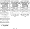
- the gateway information TLV announced by the portal system A to the portal systems B and C is shown as FIG. 15(1) , representing that the portal system priority of the portal system A is 01; the MAC address code of the portal system is A; for the services, with the service sequence being 1-100, taking the gateway of the portal system A as the main gateway, the portal system with the high backup priority is selected as the portal system in which the backup gateway is located; wherein for the backup portal system of which the backup priority is 01, its portal system priority is 02, and the MAC address code of the portal system is B; for the backup portal system of which the backup priority is 02, its portal system priority is 03, and the MAC address code of the portal system is C; for the services, with the service sequence being 101-200, taking the gateway of the portal system A as the main gateway, the portal system with the high backup priority is selected as the portal system in which the backup gateway is located; wherein for the backup portal system of which the backup priority
- the gateway information TLV announced by the portal system B to the portal system A and C is shown as FIG. 15(2) , representing that the portal system priority of the portal system A is 02; the MAC address code of the portal system is B; for the services, with the service sequence being 201-300, taking the gateway of the portal system B as the main gateway, the portal system with the high backup priority is selected as the portal system in which the backup gateway is located; wherein, for the backup portal system of which the backup priority is 01, its portal system priority is 03, and the MAC address code of the portal system is C; for the backup portal system of which the backup priority is 02, its portal system priority is 01, and the MAC address code of the portal system is A.
- the gateway information TLV announced by the portal system C to the portal system A and B is shown as FIG. 15(3) , representing that the portal system priority of the portal system C is 03; the MAC address code of the portal system is C; for the services, with the service sequence being 301-400, taking the gateway of the portal system C as the main gateway, the available portal system with the high backup priority is selected as the portal system in which the backup gateway is located; wherein, for the backup portal system of which the backup priority is 01, its portal system priority is 01, and the MAC address code of the portal system is A; for the backup portal system of which the backup priority is 02, its portal system priority is 02, and the MAC address code of the portal system is B.
- the portal system after receiving the gateway information of other portal systems, carries the received gateway information of other portal systems in the TLV for the mutual announcement as well, as shown in FIG. 5 , and finally the synchronization of gateway information is achieved.
- the portal systems A, B and C can obtain the information of main and backup gateways of the service, as shown in Table 3.
- Table 3 Gateway service Main gateway Select algorithm Backup gateway sequence (ranking as per the backup priority) 1-100 A 01 B, C 101-200 A 01 C, B 201-300 B 01 C, A 301-400 C 01 A, B
- step 1202 the portal systems A, B and C detect that the event which triggers switching the main and backup gateways occurs.
- the portal system A breaks down (as shown in FIG. 12 ), or the interconnection link breaks down, causing the portal system A to be isolated (as shown in FIG. 13 ), or the portal system A is made to be removed from the aggregation group due to the configuration reason, and the portal systems B and C are connected through the interconnection link, then it is still kept joining the aggregation group.
- the portal system of the present end point is required to judge whether itself is removed from the aggregation group; if yes, then step 1201 is entered; if no, then step 1203 is entered.
- step 1203 the gateway of the service or session is updated, the portal system in which the new main gateway of the service or session is located starts to forward the service or session through the main gateway, and the portal system in which the backup gateway of the service or session is located stops forwarding the service or session through the backup gateway.
- the portal system B activates its own gateway as the main gateway of the services 1-100
- the portal system C activates its own gateway as the main gateway of the services 101-200, to forward the service through the present gateway, thus not generating the flowrate cutoff.
- the portal systems B and C activates their own gateways as the main gateways of the services influenced by the fault
- the source node of the service in the network 1 is notified, such as, the node S1, to perform the service switchover.
- the portal system is removed from the aggregation group, and forwarding the service of the aggregation group is stopped, as shown in FIG. 13 .
- the portal system A is removed from the aggregation group, and then forwarding the services 1-200 from the aggregation group link is stopped.
- the portal systems B and C update the information of the main and backup gateways (as shown in Table 4), and perform the synchronization of gateway information through the DRCP, returning to step 1201.
- the gateway information TLV sent by the portal system B to the portal system C is shown as FIG. 16(1) , then it represents that the portal system priority of the portal system B is 02; the MAC address code of the portal system is B; for the services, with a service sequence being 1-100 and 201-300, taking the gateway of the portal system B as the main gateway, the portal system with the high backup priority is selected as the portal system in which the backup gateway is located; wherein, for the backup portal system of which the backup priority is 01, its portal system priority is 03, and the MAC address code of the portal system is C.
- the gateway information TLV sent by the portal system C to the portal system B is shown as is shown as FIG. 16(2) , representing that the portal system priority of the portal system C is 03; the MAC address code of the portal system is C; for the services, with the service sequence being 101-200 and 301-400, taking the gateway of the portal system C as the main gateway, the portal system with the high backup priority is selected as the portal system in which the backup gateway is located.
- the backup portal system of which the backup priority 01
- its portal system priority is 02
- the MAC address code of the portal system is B.
- the portal systems B and C can obtain the new main and backup gateway information of the service, as shown in Table 4.
- Table 4 Gateway service Main gateway Backup gateway (ranking as per the backup priority) 1-100 B (backup changed to main) C 101-200 C (backup changed to main) B 201-300 B C 301-400 C B
- the portal system A announces its own gateway information and the backup gateway select algorithm to the portal systems B and C through the DRCP, and the announced gateway information TLV is as shown in FIG. 15(1) . Meanwhile, the services 1-200 are forwarded through the present gateway, and the source node S1 of the service is notified that the gateway switchover occurs.
- the portal system B detects that the portal system A is recovered, and judges that the portal system A is the portal system in which the main gateway of the services 1-100 is located, therefore, the gateway of the portal system B is updated as the backup gateway of the services 1-100, and the service is not forwarded through the present gateway. Meanwhile, the gateway information is updated by the portal system B, and its own gateway information is announced to the portal systems A and C, which is same as shown in FIG. 15(2) .
- the portal system C detects that the portal system A is recovered, and the processing mode is same with the portal system B, it will also update its own gateway as the backup gateway of the services 101-200, and it will not forward the service through the present gateway.
- the own gateway information TLV that the portal system C announces to the portal systems A and B is the same as shown in FIG. 15(3) .
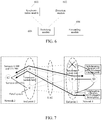
- the embodiment of the present invention further provides an apparatus for dynamically switching a gateway of distributed resilient network interconnect (DRNI), as shown in FIG. 6 , including an information synchronization module 601, an event detection module 602, a main and backup switching module 603 and a forwarding module 604, to complete the above-mentioned function.
- DRNI distributed resilient network interconnect
- the information synchronization module 601 is configured to: synchronize information of main and backup gateways of each portal system with other portal systems of a present end point.
- the information synchronization module when a system is initialized or the information of the main and backup gateways is changed, updates the information of the main and backup gateways in real time, and performs the information synchronization.
- the event detection module 602 is configured to: detect an event which triggers switching the main and backup gateways.
- the event includes:
- the information of the main and backup gateways includes the following information: a portal system identifier used for distinguishing the portal systems (which can be a portal system number or address or priority, or an identifier generated by the address and priority); a service or session identifier used for distinguishing the service or the session; and a select algorithm or coding information of gateway sequential list used for determining the main and backup gateways of the service or session.
- a portal system identifier used for distinguishing the portal systems (which can be a portal system number or address or priority, or an identifier generated by the address and priority); a service or session identifier used for distinguishing the service or the session; and a select algorithm or coding information of gateway sequential list used for determining the main and backup gateways of the service or session.
- the main and backup switching module 603 is configured to: update a gateway of a service or session when the event which triggers switching the main and backup gateways is detected, and control a present portal system to start or stop forwarding the service or session via the present portal system.
- the main and backup switchover module 603 is further used for notifying the source node of the service or session that the gateway switchover occurs.
- the new main and backup gateways of the service or session are determined according to the information of the main and backup gateways.
- the forwarding module 604 is configured to: forward a service or session which takes the gateway of the present portal system as the main gateway via the gateway of the present portal system.
- each portal system synchronizes the information of the main and backup gateways in real time.
- the portal system in which the gateway is located breaks down or the portal system in which the gateway is located is removed from the aggregation group, there is no need to reappoint the main and backup gateways. It can just realize switching the gateway of the service or session dynamically and enable the service or the session to be transmitted from another portal system in the aggregation group.
Landscapes
- Engineering & Computer Science (AREA)
- Computer Networks & Wireless Communication (AREA)
- Signal Processing (AREA)
- Data Exchanges In Wide-Area Networks (AREA)
Claims (10)
- Procédé de commutation dynamique d'une passerelle d'interconnexion de réseau résilient distribué comprenant :de synchroniser (301) l'information de passerelles principale et de secours de chaque système de portail entre un système de portail d'un point d'extrémité de DRNI et d'autres systèmes de portail d'un point d'extrémité présent ;le système de portail détectant (302) si un évènement qui déclenche la commutation des passerelles principale et de secours a eu lieu ou non ; etmettre à jour (303) une passerelle d'un service ou d'une session selon l'information des passerelles principale et de secours quand l'évènement qui déclenche la commutation des passerelles principale et de secours est détecté, c'est à dire, un système de portail dans lequel une nouvelle passerelle principale du service ou de la session est située commençant à transférer le service ou la session via la passerelle principale, et un système de portail dans lequel une passerelle de secours du service ou de la session est située arrêtant de transférer le service ou la session via la passerelle de secours ;dans lequel l'information des passerelles principale et de secours comprend : un identificateur de système de portail, un identificateur de service ou de session, et un algorithme de sélection ou une information de codage d'une liste séquentielle de passerelles utilisée pour déterminer les passerelles principale et de secours du service ou de la session.
- Procédé selon la revendication 1, dans lequel l'évènement comprend l'un de ce qui suit :erreur ou correction d'erreur d'un système de portail du présent point d'extrémité ;erreur ou correction d'erreur d'un lien d'interconnexion du système de portail du présent point d'extrémité ; etle système de portail du présent point d'extrémité étant enlevé de ou rejoignant un groupe d'agrégation.
- Procédé selon la revendication 1, dans lequel :de nouvelles passerelles principale et de secours du service ou de la session sont déterminées selon une information obtenue des passerelles principale et de secours.
- Procédé selon la revendication 1, dans lequel :synchroniser l'information des passerelles principale et de secours de chaque système de portail entre le système de portail du point d'extrémité de DRNI et d'autres systèmes de portail du présent point d'extrémité comprend :quand un système est initialisé ou l'information des passerelles principale et de secours est changée, chaque système de portail mettant à jour l'information des passerelles principale et de secours en temps réel, et réalisant une synchronisation d'information.
- Procédé selon la revendication 1, dans lequel :l'information des passerelles principale et de secours est synchronisée au moyen qu'un message de protocole de commande à relai distribué supporte un type-longueur-valeur TLV.
- Dispositif de communication dynamique d'une passerelle d'interconnexion de réseau résilient distribué DRNI qui est appliqué à un système de portail, comprenant :un module de synchronisation d'information (601) configuré pour : synchroniser une information des passerelles principale et de secours de chaque système de portail avec d'autres systèmes de portails d'un présent point d'extrémité ;un module de détection d'évènement (602) configuré pour :détecter un évènement qui déclenche la commutation des passerelles principale et de secours ;un module de commutation principal et de secours (603) configuré pour : mettre à jour une passerelle d'un service ou d'une session quand l'évènement qui déclenche la commutation des passerelles principale et de secours est détecté, et commander un système de portail présent pour commencer ou arrêter de transférer le service ou la session via une passerelle du système de portail présent ; etun module de transfert (604) configuré pour : transférer un service ou une session qui prend la passerelle du présent système de portail comme la passerelle principale via la passerelle du présent système de portail ;dans lequel l'information des passerelles principale et de secours comprend : un identificateur de système de portail, un identificateur de service ou de session, et un algorithme de sélection ou une information de codage d'une liste séquentielle de passerelles utilisée pour déterminer les passerelles principale et de secours backup du service ou de la session.
- Dispositif selon la revendication 6, dans lequel l'évènement comprend l'un de ce qui suit :erreur ou correction d'erreur d'un système de portail du présent point d'extrémité ;erreur ou correction d'erreur d'un lien d'interconnexion du système de portail du présent point d'extrémité ; etle système de portail du présent point d'extrémité étant enlevé de ou rejoignant un groupe d'agrégation.
- Dispositif selon la revendication 6, dans lequel :de nouvelles passerelles principale et de secours du service ou de la session sont déterminées selon une information obtenue des passerelles principale et de secours.
- Dispositif selon la revendication 6, dans lequel :le module de synchronisation d'information est configuré pour :synchroniser l'information des passerelles principale et de secours de chaque système de portail avec d'autres systèmes de portail du présent point d'extrémité par le mode suivant :quand un système est initialisé ou l'information des passerelles principale et de secours est changée, mettre à jour l'information des passerelles principale et de secours en temps réel, et réaliser une synchronisation d'information.
- Dispositif selon la revendication 6, dans lequel :l'information des passerelles principale et de secours est synchronisée de telle manière qu'un message de protocole de commande à relai distribué DRCP supporte un type-longueur-valeur TLV.
Applications Claiming Priority (2)
| Application Number | Priority Date | Filing Date | Title |
|---|---|---|---|
| CN201210398054.9A CN103780407B (zh) | 2012-10-18 | 2012-10-18 | 分布式弹性网络互连(drni)中网关动态切换方法和装置 |
| PCT/CN2013/083628 WO2014059844A1 (fr) | 2012-10-18 | 2013-09-17 | Procédé et dispositif de commutation dynamique d'une passerelle d'interconnexion de réseau distribué résilient (drni) |
Publications (3)
| Publication Number | Publication Date |
|---|---|
| EP2911341A1 EP2911341A1 (fr) | 2015-08-26 |
| EP2911341A4 EP2911341A4 (fr) | 2015-09-30 |
| EP2911341B1 true EP2911341B1 (fr) | 2017-02-08 |
Family
ID=50487545
Family Applications (1)
| Application Number | Title | Priority Date | Filing Date |
|---|---|---|---|
| EP13847852.4A Active EP2911341B1 (fr) | 2012-10-18 | 2013-09-17 | Procédé et dispositif de commutation dynamique d'une passerelle d'interconnexion de réseau distribué résilient (drni) |
Country Status (4)
| Country | Link |
|---|---|
| US (1) | US20150365320A1 (fr) |
| EP (1) | EP2911341B1 (fr) |
| CN (1) | CN103780407B (fr) |
| WO (1) | WO2014059844A1 (fr) |
Families Citing this family (19)
| Publication number | Priority date | Publication date | Assignee | Title |
|---|---|---|---|---|
| US9509556B2 (en) | 2013-04-23 | 2016-11-29 | Telefonaktiebolaget L M Ericsson (Publ) | Method and system for synchronizing with neighbor in a distributed resilient network interconnect (DRNI) link aggregation group |
| US9497132B2 (en) | 2013-04-23 | 2016-11-15 | Telefonaktiebolaget Lm Ericsson (Publ) | Method and system of implementing conversation-sensitive collection for a link aggregation group |
| US9553798B2 (en) | 2013-04-23 | 2017-01-24 | Telefonaktiebolaget L M Ericsson (Publ) | Method and system of updating conversation allocation in link aggregation |
| US10476698B2 (en) * | 2014-03-20 | 2019-11-12 | Avago Technologies International Sales Pte. Limited | Redundent virtual link aggregation group |
| US9813290B2 (en) * | 2014-08-29 | 2017-11-07 | Telefonaktiebolaget Lm Ericsson (Publ) | Method and system for supporting distributed relay control protocol (DRCP) operations upon misconfiguration |
| WO2017184008A1 (fr) * | 2016-04-19 | 2017-10-26 | Ringcentral, Inc | Systèmes et procédés permettant d'améliorer la communication de données multimédia sur un réseau |
| CN106126371A (zh) * | 2016-06-15 | 2016-11-16 | 腾讯科技(深圳)有限公司 | 数据回档方法、装置及系统 |
| US10802924B2 (en) * | 2017-07-25 | 2020-10-13 | Sap Se | Asynchronous session storing |
| CN110572275B (zh) * | 2019-08-01 | 2022-09-09 | 新华三技术有限公司成都分公司 | 一种网卡切换方法、装置、服务器及计算机可读存储介质 |
| US11336562B2 (en) | 2019-08-06 | 2022-05-17 | Hughes Network Systems, Llc | System and method for generic diversity gateway switching for a satellite communication system |
| US10938652B1 (en) * | 2019-08-20 | 2021-03-02 | Hughes Network Systems, Llc | Gateway diversity switching |
| CN110677339A (zh) * | 2019-10-08 | 2020-01-10 | 北京东土军悦科技有限公司 | 网关节点间冗余保护方法、装置、网关设备及储存介质 |
| EP3920412B1 (fr) * | 2020-06-04 | 2023-06-21 | Soltec Innovations S.L. | Mise en service du suiveur solaire |
| JP7371784B2 (ja) * | 2020-07-13 | 2023-10-31 | 日本電信電話株式会社 | 通信中継装置、通信中継システム、通信中継方法、および、プログラム |
| CN112968836B (zh) * | 2021-01-31 | 2022-05-27 | 新华三信息安全技术有限公司 | 跨设备聚合链路配置方法、装置、设备及可读存储介质 |
| CN113286101B (zh) * | 2021-05-21 | 2022-04-26 | 新华三技术有限公司 | 一种音视频流切换方法及装置 |
| CN114157555B (zh) * | 2021-11-12 | 2023-05-26 | 杭州迪普科技股份有限公司 | 一种访问信息同步方法 |
| US11303150B1 (en) | 2021-12-03 | 2022-04-12 | DataRemote, Inc. | Apparatus for internet and power backup |
| US12609008B1 (en) * | 2022-09-20 | 2026-04-21 | R&D Industries, Inc. | Autonomous network connectivity systems and related devices and methods |
Family Cites Families (6)
| Publication number | Priority date | Publication date | Assignee | Title |
|---|---|---|---|---|
| US8020203B2 (en) * | 2007-12-03 | 2011-09-13 | Novell, Inc. | Techniques for high availability of virtual private networks (VPN's) |
| CN102549979A (zh) * | 2009-07-10 | 2012-07-04 | 诺基亚西门子通信公司 | 用于传送业务的方法和设备 |
| US8839023B2 (en) * | 2011-03-10 | 2014-09-16 | Cisco Technology, Inc. | Transmitting network information using link or port aggregation protocols |
| WO2011157145A2 (fr) * | 2011-05-31 | 2011-12-22 | 华为技术有限公司 | Procédé de basculement principal / appoint entre dispositifs de communications, système et dispositif de demande de service |
| CN102315926B (zh) * | 2011-10-11 | 2014-12-24 | 华为数字技术(成都)有限公司 | 一种主用设备选择方法、网关设备及网络系统 |
| US9602348B2 (en) * | 2012-05-15 | 2017-03-21 | Telefonaktiebolaget Lm Ericsson | Methods and apparatus for detecting and handling split brain issues in a link aggregation group |
-
2012
- 2012-10-18 CN CN201210398054.9A patent/CN103780407B/zh active Active
-
2013
- 2013-09-17 WO PCT/CN2013/083628 patent/WO2014059844A1/fr not_active Ceased
- 2013-09-17 US US14/436,584 patent/US20150365320A1/en not_active Abandoned
- 2013-09-17 EP EP13847852.4A patent/EP2911341B1/fr active Active
Non-Patent Citations (1)
| Title |
|---|
| None * |
Also Published As
| Publication number | Publication date |
|---|---|
| CN103780407A (zh) | 2014-05-07 |
| US20150365320A1 (en) | 2015-12-17 |
| CN103780407B (zh) | 2018-07-06 |
| WO2014059844A1 (fr) | 2014-04-24 |
| EP2911341A1 (fr) | 2015-08-26 |
| EP2911341A4 (fr) | 2015-09-30 |
Similar Documents
| Publication | Publication Date | Title |
|---|---|---|
| EP2911341A1 (fr) | Procédé et dispositif de commutation dynamique d'une passerelle d'interconnexion de réseau distribué résilient (drni) | |
| US7944815B2 (en) | System and method for network recovery from multiple link failures | |
| EP2458797B1 (fr) | Procédé, dispositif et système de mise à jour d'informations de topologie de réseau en anneau | |
| JP5152642B2 (ja) | パケットリングネットワークシステム、パケット転送方法、およびノード | |
| US20150026507A1 (en) | Transport control server, network system and transport control method | |
| CN101399737A (zh) | 用于以太环网的链路聚合组的保护方法及装置 | |
| CN101729426B (zh) | 一种虚拟路由冗余协议主备用设备快速切换的方法及系统 | |
| CN103607293B (zh) | 一种流量保护方法及设备 | |
| CN112367254B (zh) | 跨设备链路聚合方法、装置和电子设备 | |
| CN103873336A (zh) | 分布式弹性网络互连的业务承载方法及装置 | |
| CN102780615B (zh) | 一种链路备份方法和路由转发设备 | |
| EP3029883B1 (fr) | Procédé et appareil de protection de réseau, noeud d'anneau suivant et système | |
| CN102857316B (zh) | 一种实现源环网保护的方法及系统 | |
| CN108234358B (zh) | 一种组播报文传输方法、装置及机器可读存储介质 | |
| CN102025561B (zh) | 一种以太环网中刷新mac的方法及系统 | |
| CN102739535A (zh) | 一种线卡离线的保护方法和系统 | |
| CN102932249B (zh) | 一种vrrp报文的传输方法和装置 | |
| JP2012175425A (ja) | 中継装置および中継方法 | |
| CN105207792A (zh) | 非联动的伪线网关保护系统及其伪线网关保护方法 | |
| CN102946321B (zh) | 一种基于irf网络的故障处理方法和设备 | |
| CN102014033B (zh) | 环网故障节点实现业务恢复的方法和系统 | |
| CN102868620B (zh) | 跨环业务保护方法及装置 | |
| CN101958812A (zh) | 链路故障检测方法及系统 | |
| CN114301763A (zh) | 分布式集群故障的处理方法及系统、电子设备及存储介质 | |
| CN119814640A (zh) | 一种通告路由的方法和网络设备 |
Legal Events
| Date | Code | Title | Description |
|---|---|---|---|
| PUAI | Public reference made under article 153(3) epc to a published international application that has entered the european phase |
Free format text: ORIGINAL CODE: 0009012 |
|
| 17P | Request for examination filed |
Effective date: 20150518 |
|
| AK | Designated contracting states |
Kind code of ref document: A1 Designated state(s): AL AT BE BG CH CY CZ DE DK EE ES FI FR GB GR HR HU IE IS IT LI LT LU LV MC MK MT NL NO PL PT RO RS SE SI SK SM TR |
|
| AX | Request for extension of the european patent |
Extension state: BA ME |
|
| RA4 | Supplementary search report drawn up and despatched (corrected) |
Effective date: 20150831 |
|
| RIC1 | Information provided on ipc code assigned before grant |
Ipc: H04L 12/891 20130101ALI20150825BHEP Ipc: H04L 12/703 20130101ALI20150825BHEP Ipc: H04L 12/24 20060101AFI20150825BHEP Ipc: H04L 12/709 20130101ALI20150825BHEP |
|
| DAX | Request for extension of the european patent (deleted) | ||
| GRAP | Despatch of communication of intention to grant a patent |
Free format text: ORIGINAL CODE: EPIDOSNIGR1 |
|
| RIC1 | Information provided on ipc code assigned before grant |
Ipc: H04L 12/703 20130101ALI20160727BHEP Ipc: H04L 12/24 20060101AFI20160727BHEP Ipc: H04L 12/891 20130101ALI20160727BHEP Ipc: H04L 12/709 20130101ALI20160727BHEP |
|
| INTG | Intention to grant announced |
Effective date: 20160823 |
|
| GRAS | Grant fee paid |
Free format text: ORIGINAL CODE: EPIDOSNIGR3 |
|
| GRAA | (expected) grant |
Free format text: ORIGINAL CODE: 0009210 |
|
| AK | Designated contracting states |
Kind code of ref document: B1 Designated state(s): AL AT BE BG CH CY CZ DE DK EE ES FI FR GB GR HR HU IE IS IT LI LT LU LV MC MK MT NL NO PL PT RO RS SE SI SK SM TR |
|
| REG | Reference to a national code |
Ref country code: GB Ref legal event code: FG4D |
|
| REG | Reference to a national code |
Ref country code: CH Ref legal event code: EP Ref country code: AT Ref legal event code: REF Ref document number: 867268 Country of ref document: AT Kind code of ref document: T Effective date: 20170215 |
|
| REG | Reference to a national code |
Ref country code: IE Ref legal event code: FG4D |
|
| REG | Reference to a national code |
Ref country code: DE Ref legal event code: R096 Ref document number: 602013017408 Country of ref document: DE |
|
| REG | Reference to a national code |
Ref country code: CH Ref legal event code: NV Representative=s name: NOVAGRAAF INTERNATIONAL SA, CH |
|
| REG | Reference to a national code |
Ref country code: LT Ref legal event code: MG4D |
|
| REG | Reference to a national code |
Ref country code: NL Ref legal event code: MP Effective date: 20170208 |
|
| REG | Reference to a national code |
Ref country code: AT Ref legal event code: MK05 Ref document number: 867268 Country of ref document: AT Kind code of ref document: T Effective date: 20170208 |
|
| PG25 | Lapsed in a contracting state [announced via postgrant information from national office to epo] |
Ref country code: HR Free format text: LAPSE BECAUSE OF FAILURE TO SUBMIT A TRANSLATION OF THE DESCRIPTION OR TO PAY THE FEE WITHIN THE PRESCRIBED TIME-LIMIT Effective date: 20170208 Ref country code: NO Free format text: LAPSE BECAUSE OF FAILURE TO SUBMIT A TRANSLATION OF THE DESCRIPTION OR TO PAY THE FEE WITHIN THE PRESCRIBED TIME-LIMIT Effective date: 20170508 Ref country code: FI Free format text: LAPSE BECAUSE OF FAILURE TO SUBMIT A TRANSLATION OF THE DESCRIPTION OR TO PAY THE FEE WITHIN THE PRESCRIBED TIME-LIMIT Effective date: 20170208 Ref country code: GR Free format text: LAPSE BECAUSE OF FAILURE TO SUBMIT A TRANSLATION OF THE DESCRIPTION OR TO PAY THE FEE WITHIN THE PRESCRIBED TIME-LIMIT Effective date: 20170509 Ref country code: LT Free format text: LAPSE BECAUSE OF FAILURE TO SUBMIT A TRANSLATION OF THE DESCRIPTION OR TO PAY THE FEE WITHIN THE PRESCRIBED TIME-LIMIT Effective date: 20170208 |
|
| PG25 | Lapsed in a contracting state [announced via postgrant information from national office to epo] |
Ref country code: BG Free format text: LAPSE BECAUSE OF FAILURE TO SUBMIT A TRANSLATION OF THE DESCRIPTION OR TO PAY THE FEE WITHIN THE PRESCRIBED TIME-LIMIT Effective date: 20170508 Ref country code: ES Free format text: LAPSE BECAUSE OF FAILURE TO SUBMIT A TRANSLATION OF THE DESCRIPTION OR TO PAY THE FEE WITHIN THE PRESCRIBED TIME-LIMIT Effective date: 20170208 Ref country code: LV Free format text: LAPSE BECAUSE OF FAILURE TO SUBMIT A TRANSLATION OF THE DESCRIPTION OR TO PAY THE FEE WITHIN THE PRESCRIBED TIME-LIMIT Effective date: 20170208 Ref country code: NL Free format text: LAPSE BECAUSE OF FAILURE TO SUBMIT A TRANSLATION OF THE DESCRIPTION OR TO PAY THE FEE WITHIN THE PRESCRIBED TIME-LIMIT Effective date: 20170208 Ref country code: PT Free format text: LAPSE BECAUSE OF FAILURE TO SUBMIT A TRANSLATION OF THE DESCRIPTION OR TO PAY THE FEE WITHIN THE PRESCRIBED TIME-LIMIT Effective date: 20170608 Ref country code: AT Free format text: LAPSE BECAUSE OF FAILURE TO SUBMIT A TRANSLATION OF THE DESCRIPTION OR TO PAY THE FEE WITHIN THE PRESCRIBED TIME-LIMIT Effective date: 20170208 Ref country code: SE Free format text: LAPSE BECAUSE OF FAILURE TO SUBMIT A TRANSLATION OF THE DESCRIPTION OR TO PAY THE FEE WITHIN THE PRESCRIBED TIME-LIMIT Effective date: 20170208 Ref country code: RS Free format text: LAPSE BECAUSE OF FAILURE TO SUBMIT A TRANSLATION OF THE DESCRIPTION OR TO PAY THE FEE WITHIN THE PRESCRIBED TIME-LIMIT Effective date: 20170208 |
|
| REG | Reference to a national code |
Ref country code: FR Ref legal event code: PLFP Year of fee payment: 5 |
|
| PG25 | Lapsed in a contracting state [announced via postgrant information from national office to epo] |
Ref country code: SK Free format text: LAPSE BECAUSE OF FAILURE TO SUBMIT A TRANSLATION OF THE DESCRIPTION OR TO PAY THE FEE WITHIN THE PRESCRIBED TIME-LIMIT Effective date: 20170208 Ref country code: RO Free format text: LAPSE BECAUSE OF FAILURE TO SUBMIT A TRANSLATION OF THE DESCRIPTION OR TO PAY THE FEE WITHIN THE PRESCRIBED TIME-LIMIT Effective date: 20170208 Ref country code: CZ Free format text: LAPSE BECAUSE OF FAILURE TO SUBMIT A TRANSLATION OF THE DESCRIPTION OR TO PAY THE FEE WITHIN THE PRESCRIBED TIME-LIMIT Effective date: 20170208 Ref country code: EE Free format text: LAPSE BECAUSE OF FAILURE TO SUBMIT A TRANSLATION OF THE DESCRIPTION OR TO PAY THE FEE WITHIN THE PRESCRIBED TIME-LIMIT Effective date: 20170208 Ref country code: IT Free format text: LAPSE BECAUSE OF FAILURE TO SUBMIT A TRANSLATION OF THE DESCRIPTION OR TO PAY THE FEE WITHIN THE PRESCRIBED TIME-LIMIT Effective date: 20170208 |
|
| REG | Reference to a national code |
Ref country code: DE Ref legal event code: R097 Ref document number: 602013017408 Country of ref document: DE |
|
| PG25 | Lapsed in a contracting state [announced via postgrant information from national office to epo] |
Ref country code: PL Free format text: LAPSE BECAUSE OF FAILURE TO SUBMIT A TRANSLATION OF THE DESCRIPTION OR TO PAY THE FEE WITHIN THE PRESCRIBED TIME-LIMIT Effective date: 20170208 Ref country code: DK Free format text: LAPSE BECAUSE OF FAILURE TO SUBMIT A TRANSLATION OF THE DESCRIPTION OR TO PAY THE FEE WITHIN THE PRESCRIBED TIME-LIMIT Effective date: 20170208 Ref country code: SM Free format text: LAPSE BECAUSE OF FAILURE TO SUBMIT A TRANSLATION OF THE DESCRIPTION OR TO PAY THE FEE WITHIN THE PRESCRIBED TIME-LIMIT Effective date: 20170208 |
|
| PLBE | No opposition filed within time limit |
Free format text: ORIGINAL CODE: 0009261 |
|
| STAA | Information on the status of an ep patent application or granted ep patent |
Free format text: STATUS: NO OPPOSITION FILED WITHIN TIME LIMIT |
|
| 26N | No opposition filed |
Effective date: 20171109 |
|
| PG25 | Lapsed in a contracting state [announced via postgrant information from national office to epo] |
Ref country code: SI Free format text: LAPSE BECAUSE OF FAILURE TO SUBMIT A TRANSLATION OF THE DESCRIPTION OR TO PAY THE FEE WITHIN THE PRESCRIBED TIME-LIMIT Effective date: 20170208 |
|
| REG | Reference to a national code |
Ref country code: DE Ref legal event code: R119 Ref document number: 602013017408 Country of ref document: DE |
|
| PG25 | Lapsed in a contracting state [announced via postgrant information from national office to epo] |
Ref country code: MC Free format text: LAPSE BECAUSE OF FAILURE TO SUBMIT A TRANSLATION OF THE DESCRIPTION OR TO PAY THE FEE WITHIN THE PRESCRIBED TIME-LIMIT Effective date: 20170208 |
|
| REG | Reference to a national code |
Ref country code: IE Ref legal event code: MM4A |
|
| REG | Reference to a national code |
Ref country code: BE Ref legal event code: MM Effective date: 20170930 |
|
| PG25 | Lapsed in a contracting state [announced via postgrant information from national office to epo] |
Ref country code: LU Free format text: LAPSE BECAUSE OF NON-PAYMENT OF DUE FEES Effective date: 20170917 |
|
| PG25 | Lapsed in a contracting state [announced via postgrant information from national office to epo] |
Ref country code: DE Free format text: LAPSE BECAUSE OF NON-PAYMENT OF DUE FEES Effective date: 20180404 Ref country code: IE Free format text: LAPSE BECAUSE OF NON-PAYMENT OF DUE FEES Effective date: 20170917 |
|
| PG25 | Lapsed in a contracting state [announced via postgrant information from national office to epo] |
Ref country code: BE Free format text: LAPSE BECAUSE OF NON-PAYMENT OF DUE FEES Effective date: 20170930 |
|
| REG | Reference to a national code |
Ref country code: FR Ref legal event code: PLFP Year of fee payment: 6 |
|
| PG25 | Lapsed in a contracting state [announced via postgrant information from national office to epo] |
Ref country code: MT Free format text: LAPSE BECAUSE OF NON-PAYMENT OF DUE FEES Effective date: 20170917 |
|
| PG25 | Lapsed in a contracting state [announced via postgrant information from national office to epo] |
Ref country code: HU Free format text: LAPSE BECAUSE OF FAILURE TO SUBMIT A TRANSLATION OF THE DESCRIPTION OR TO PAY THE FEE WITHIN THE PRESCRIBED TIME-LIMIT; INVALID AB INITIO Effective date: 20130917 |
|
| PG25 | Lapsed in a contracting state [announced via postgrant information from national office to epo] |
Ref country code: CY Free format text: LAPSE BECAUSE OF FAILURE TO SUBMIT A TRANSLATION OF THE DESCRIPTION OR TO PAY THE FEE WITHIN THE PRESCRIBED TIME-LIMIT Effective date: 20170208 |
|
| PG25 | Lapsed in a contracting state [announced via postgrant information from national office to epo] |
Ref country code: MK Free format text: LAPSE BECAUSE OF FAILURE TO SUBMIT A TRANSLATION OF THE DESCRIPTION OR TO PAY THE FEE WITHIN THE PRESCRIBED TIME-LIMIT Effective date: 20170208 |
|
| PG25 | Lapsed in a contracting state [announced via postgrant information from national office to epo] |
Ref country code: TR Free format text: LAPSE BECAUSE OF FAILURE TO SUBMIT A TRANSLATION OF THE DESCRIPTION OR TO PAY THE FEE WITHIN THE PRESCRIBED TIME-LIMIT Effective date: 20170208 |
|
| PG25 | Lapsed in a contracting state [announced via postgrant information from national office to epo] |
Ref country code: AL Free format text: LAPSE BECAUSE OF FAILURE TO SUBMIT A TRANSLATION OF THE DESCRIPTION OR TO PAY THE FEE WITHIN THE PRESCRIBED TIME-LIMIT Effective date: 20170208 Ref country code: IS Free format text: LAPSE BECAUSE OF FAILURE TO SUBMIT A TRANSLATION OF THE DESCRIPTION OR TO PAY THE FEE WITHIN THE PRESCRIBED TIME-LIMIT Effective date: 20170608 |
|
| P01 | Opt-out of the competence of the unified patent court (upc) registered |
Effective date: 20230530 |
|
| REG | Reference to a national code |
Ref country code: CH Ref legal event code: U11 Free format text: ST27 STATUS EVENT CODE: U-0-0-U10-U11 (AS PROVIDED BY THE NATIONAL OFFICE) Effective date: 20251001 |
|
| PGFP | Annual fee paid to national office [announced via postgrant information from national office to epo] |
Ref country code: GB Payment date: 20250703 Year of fee payment: 13 |
|
| PGFP | Annual fee paid to national office [announced via postgrant information from national office to epo] |
Ref country code: FR Payment date: 20250708 Year of fee payment: 13 |
|
| PGFP | Annual fee paid to national office [announced via postgrant information from national office to epo] |
Ref country code: CH Payment date: 20251001 Year of fee payment: 13 |