EP2912314B1 - Système de refoulement de gaz pour compresseur frigorifique et compresseur frigorifique - Google Patents
Système de refoulement de gaz pour compresseur frigorifique et compresseur frigorifique Download PDFInfo
- Publication number
- EP2912314B1 EP2912314B1 EP13792243.1A EP13792243A EP2912314B1 EP 2912314 B1 EP2912314 B1 EP 2912314B1 EP 13792243 A EP13792243 A EP 13792243A EP 2912314 B1 EP2912314 B1 EP 2912314B1
- Authority
- EP
- European Patent Office
- Prior art keywords
- discharge
- end wall
- hollow body
- valve plate
- refrigeration compressor
- Prior art date
- Legal status (The legal status is an assumption and is not a legal conclusion. Google has not performed a legal analysis and makes no representation as to the accuracy of the status listed.)
- Not-in-force
Links
- 238000005057 refrigeration Methods 0.000 title claims description 25
- 239000003507 refrigerant Substances 0.000 claims description 13
- 230000006835 compression Effects 0.000 claims description 8
- 238000007906 compression Methods 0.000 claims description 8
- 230000001133 acceleration Effects 0.000 claims description 2
- 238000010276 construction Methods 0.000 description 13
- 238000007789 sealing Methods 0.000 description 10
- 238000011144 upstream manufacturing Methods 0.000 description 6
- 238000004891 communication Methods 0.000 description 5
- 239000012530 fluid Substances 0.000 description 5
- 230000009467 reduction Effects 0.000 description 5
- 230000010349 pulsation Effects 0.000 description 3
- 238000006073 displacement reaction Methods 0.000 description 2
- 230000001965 increasing effect Effects 0.000 description 2
- 239000011810 insulating material Substances 0.000 description 2
- 238000009413 insulation Methods 0.000 description 2
- 230000007246 mechanism Effects 0.000 description 2
- 229910001092 metal group alloy Inorganic materials 0.000 description 2
- 238000005086 pumping Methods 0.000 description 2
- 230000009471 action Effects 0.000 description 1
- 239000000853 adhesive Substances 0.000 description 1
- 230000001070 adhesive effect Effects 0.000 description 1
- 239000002313 adhesive film Substances 0.000 description 1
- 230000002238 attenuated effect Effects 0.000 description 1
- 238000005219 brazing Methods 0.000 description 1
- 230000000694 effects Effects 0.000 description 1
- 238000005265 energy consumption Methods 0.000 description 1
- 239000003623 enhancer Substances 0.000 description 1
- 230000002708 enhancing effect Effects 0.000 description 1
- 238000012423 maintenance Methods 0.000 description 1
- 239000000463 material Substances 0.000 description 1
- 230000010355 oscillation Effects 0.000 description 1
- 238000010992 reflux Methods 0.000 description 1
- 230000000717 retained effect Effects 0.000 description 1
- 230000007480 spreading Effects 0.000 description 1
Images



Classifications
-
- F—MECHANICAL ENGINEERING; LIGHTING; HEATING; WEAPONS; BLASTING
- F04—POSITIVE - DISPLACEMENT MACHINES FOR LIQUIDS; PUMPS FOR LIQUIDS OR ELASTIC FLUIDS
- F04B—POSITIVE-DISPLACEMENT MACHINES FOR LIQUIDS; PUMPS
- F04B39/00—Component parts, details, or accessories, of pumps or pumping systems specially adapted for elastic fluids, not otherwise provided for in, or of interest apart from, groups F04B25/00 - F04B37/00
- F04B39/0027—Pulsation and noise damping means
- F04B39/0055—Pulsation and noise damping means with a special shape of fluid passage, e.g. bends, throttles, diameter changes, pipes
-
- F—MECHANICAL ENGINEERING; LIGHTING; HEATING; WEAPONS; BLASTING
- F04—POSITIVE - DISPLACEMENT MACHINES FOR LIQUIDS; PUMPS FOR LIQUIDS OR ELASTIC FLUIDS
- F04B—POSITIVE-DISPLACEMENT MACHINES FOR LIQUIDS; PUMPS
- F04B53/00—Component parts, details or accessories not provided for in, or of interest apart from, groups F04B1/00 - F04B23/00 or F04B39/00 - F04B47/00
- F04B53/10—Valves; Arrangement of valves
- F04B53/1085—Valves; Arrangement of valves having means for limiting the opening height
-
- F—MECHANICAL ENGINEERING; LIGHTING; HEATING; WEAPONS; BLASTING
- F04—POSITIVE - DISPLACEMENT MACHINES FOR LIQUIDS; PUMPS FOR LIQUIDS OR ELASTIC FLUIDS
- F04B—POSITIVE-DISPLACEMENT MACHINES FOR LIQUIDS; PUMPS
- F04B39/00—Component parts, details, or accessories, of pumps or pumping systems specially adapted for elastic fluids, not otherwise provided for in, or of interest apart from, groups F04B25/00 - F04B37/00
- F04B39/0027—Pulsation and noise damping means
-
- F—MECHANICAL ENGINEERING; LIGHTING; HEATING; WEAPONS; BLASTING
- F04—POSITIVE - DISPLACEMENT MACHINES FOR LIQUIDS; PUMPS FOR LIQUIDS OR ELASTIC FLUIDS
- F04B—POSITIVE-DISPLACEMENT MACHINES FOR LIQUIDS; PUMPS
- F04B39/00—Component parts, details, or accessories, of pumps or pumping systems specially adapted for elastic fluids, not otherwise provided for in, or of interest apart from, groups F04B25/00 - F04B37/00
- F04B39/0027—Pulsation and noise damping means
- F04B39/0055—Pulsation and noise damping means with a special shape of fluid passage, e.g. bends, throttles, diameter changes, pipes
- F04B39/0061—Pulsation and noise damping means with a special shape of fluid passage, e.g. bends, throttles, diameter changes, pipes using muffler volumes
-
- F—MECHANICAL ENGINEERING; LIGHTING; HEATING; WEAPONS; BLASTING
- F04—POSITIVE - DISPLACEMENT MACHINES FOR LIQUIDS; PUMPS FOR LIQUIDS OR ELASTIC FLUIDS
- F04B—POSITIVE-DISPLACEMENT MACHINES FOR LIQUIDS; PUMPS
- F04B39/00—Component parts, details, or accessories, of pumps or pumping systems specially adapted for elastic fluids, not otherwise provided for in, or of interest apart from, groups F04B25/00 - F04B37/00
- F04B39/06—Cooling; Heating; Prevention of freezing
-
- F—MECHANICAL ENGINEERING; LIGHTING; HEATING; WEAPONS; BLASTING
- F04—POSITIVE - DISPLACEMENT MACHINES FOR LIQUIDS; PUMPS FOR LIQUIDS OR ELASTIC FLUIDS
- F04B—POSITIVE-DISPLACEMENT MACHINES FOR LIQUIDS; PUMPS
- F04B39/00—Component parts, details, or accessories, of pumps or pumping systems specially adapted for elastic fluids, not otherwise provided for in, or of interest apart from, groups F04B25/00 - F04B37/00
- F04B39/06—Cooling; Heating; Prevention of freezing
- F04B39/064—Cooling by a cooling jacket in the pump casing
-
- F—MECHANICAL ENGINEERING; LIGHTING; HEATING; WEAPONS; BLASTING
- F04—POSITIVE - DISPLACEMENT MACHINES FOR LIQUIDS; PUMPS FOR LIQUIDS OR ELASTIC FLUIDS
- F04B—POSITIVE-DISPLACEMENT MACHINES FOR LIQUIDS; PUMPS
- F04B39/00—Component parts, details, or accessories, of pumps or pumping systems specially adapted for elastic fluids, not otherwise provided for in, or of interest apart from, groups F04B25/00 - F04B37/00
- F04B39/10—Adaptations or arrangements of distribution members
-
- F—MECHANICAL ENGINEERING; LIGHTING; HEATING; WEAPONS; BLASTING
- F04—POSITIVE - DISPLACEMENT MACHINES FOR LIQUIDS; PUMPS FOR LIQUIDS OR ELASTIC FLUIDS
- F04B—POSITIVE-DISPLACEMENT MACHINES FOR LIQUIDS; PUMPS
- F04B39/00—Component parts, details, or accessories, of pumps or pumping systems specially adapted for elastic fluids, not otherwise provided for in, or of interest apart from, groups F04B25/00 - F04B37/00
- F04B39/12—Casings; Cylinders; Cylinder heads; Fluid connections
- F04B39/121—Casings
-
- F—MECHANICAL ENGINEERING; LIGHTING; HEATING; WEAPONS; BLASTING
- F04—POSITIVE - DISPLACEMENT MACHINES FOR LIQUIDS; PUMPS FOR LIQUIDS OR ELASTIC FLUIDS
- F04B—POSITIVE-DISPLACEMENT MACHINES FOR LIQUIDS; PUMPS
- F04B39/00—Component parts, details, or accessories, of pumps or pumping systems specially adapted for elastic fluids, not otherwise provided for in, or of interest apart from, groups F04B25/00 - F04B37/00
- F04B39/12—Casings; Cylinders; Cylinder heads; Fluid connections
- F04B39/123—Fluid connections
-
- F—MECHANICAL ENGINEERING; LIGHTING; HEATING; WEAPONS; BLASTING
- F04—POSITIVE - DISPLACEMENT MACHINES FOR LIQUIDS; PUMPS FOR LIQUIDS OR ELASTIC FLUIDS
- F04B—POSITIVE-DISPLACEMENT MACHINES FOR LIQUIDS; PUMPS
- F04B39/00—Component parts, details, or accessories, of pumps or pumping systems specially adapted for elastic fluids, not otherwise provided for in, or of interest apart from, groups F04B25/00 - F04B37/00
- F04B39/12—Casings; Cylinders; Cylinder heads; Fluid connections
- F04B39/125—Cylinder heads
-
- F—MECHANICAL ENGINEERING; LIGHTING; HEATING; WEAPONS; BLASTING
- F04—POSITIVE - DISPLACEMENT MACHINES FOR LIQUIDS; PUMPS FOR LIQUIDS OR ELASTIC FLUIDS
- F04B—POSITIVE-DISPLACEMENT MACHINES FOR LIQUIDS; PUMPS
- F04B39/00—Component parts, details, or accessories, of pumps or pumping systems specially adapted for elastic fluids, not otherwise provided for in, or of interest apart from, groups F04B25/00 - F04B37/00
- F04B39/14—Provisions for readily assembling or disassembling
-
- F—MECHANICAL ENGINEERING; LIGHTING; HEATING; WEAPONS; BLASTING
- F04—POSITIVE - DISPLACEMENT MACHINES FOR LIQUIDS; PUMPS FOR LIQUIDS OR ELASTIC FLUIDS
- F04B—POSITIVE-DISPLACEMENT MACHINES FOR LIQUIDS; PUMPS
- F04B53/00—Component parts, details or accessories not provided for in, or of interest apart from, groups F04B1/00 - F04B23/00 or F04B39/00 - F04B47/00
- F04B53/001—Noise damping
-
- F—MECHANICAL ENGINEERING; LIGHTING; HEATING; WEAPONS; BLASTING
- F04—POSITIVE - DISPLACEMENT MACHINES FOR LIQUIDS; PUMPS FOR LIQUIDS OR ELASTIC FLUIDS
- F04B—POSITIVE-DISPLACEMENT MACHINES FOR LIQUIDS; PUMPS
- F04B53/00—Component parts, details or accessories not provided for in, or of interest apart from, groups F04B1/00 - F04B23/00 or F04B39/00 - F04B47/00
- F04B53/007—Cylinder heads
-
- F—MECHANICAL ENGINEERING; LIGHTING; HEATING; WEAPONS; BLASTING
- F04—POSITIVE - DISPLACEMENT MACHINES FOR LIQUIDS; PUMPS FOR LIQUIDS OR ELASTIC FLUIDS
- F04B—POSITIVE-DISPLACEMENT MACHINES FOR LIQUIDS; PUMPS
- F04B53/00—Component parts, details or accessories not provided for in, or of interest apart from, groups F04B1/00 - F04B23/00 or F04B39/00 - F04B47/00
- F04B53/10—Valves; Arrangement of valves
- F04B53/1037—Flap valves
-
- F—MECHANICAL ENGINEERING; LIGHTING; HEATING; WEAPONS; BLASTING
- F04—POSITIVE - DISPLACEMENT MACHINES FOR LIQUIDS; PUMPS FOR LIQUIDS OR ELASTIC FLUIDS
- F04B—POSITIVE-DISPLACEMENT MACHINES FOR LIQUIDS; PUMPS
- F04B53/00—Component parts, details or accessories not provided for in, or of interest apart from, groups F04B1/00 - F04B23/00 or F04B39/00 - F04B47/00
- F04B53/16—Casings; Cylinders; Cylinder liners or heads; Fluid connections
-
- F—MECHANICAL ENGINEERING; LIGHTING; HEATING; WEAPONS; BLASTING
- F16—ENGINEERING ELEMENTS AND UNITS; GENERAL MEASURES FOR PRODUCING AND MAINTAINING EFFECTIVE FUNCTIONING OF MACHINES OR INSTALLATIONS; THERMAL INSULATION IN GENERAL
- F16K—VALVES; TAPS; COCKS; ACTUATING-FLOATS; DEVICES FOR VENTING OR AERATING
- F16K15/00—Check valves
- F16K15/14—Check valves with flexible valve members
- F16K15/16—Check valves with flexible valve members with tongue-shaped laminae
Definitions
- the present invention refers to a gas discharge system for a refrigeration compressor, for example, of the reciprocating hermetic type, which is particularly driven by a linear motor, and to a compressor comprising said system. See US2009/0136365 A1 , with the closest prior art.
- One of the sources which contribute to the loss of power and mass efficiency in compressor is the gas discharge system.
- the mass efficiency is favored by eliminating or reducing the reflux, minimizing power loss due to the flow of gas through the valve.
- the pressures upstream and downstream the discharge valve are some of the variables which define the operational dynamic thereof. Such variables depend on the refrigerant gas, on the operational condition of the compressor, on the design of the discharge orifice and, specially, on the construction of the discharge filter.
- the gas compressed by the displacement of the piston (driven by a connecting rod-crankshaft mechanism, or by a resonant spring in the linear compressor) is directly discharged in a discharge chamber usually defined in the interior of the cylinder cap.
- a discharge chamber usually defined in the interior of the cylinder cap.
- the gas reaching the discharge chamber undergoes a pressure reduction, spreading in a random and turbulent manner in the interior of the discharge chamber, in the valve plate region, which results in power loss.
- the present invention has the objective of providing a gas discharge system in a refrigeration compressor, which is able to reduce the power loss of the compressed gas pumping system in the discharge of the compressor.
- the invention has the further objective of providing a gas discharge system such as mentioned above, which reduces the pressure in the cylinder and, consequently, the discharge power, thus improving the acoustic performance of the compressor and further reducing the thermal exchange between the compressed gas and the valve plate.
- Another objective of the present invention is to provide a discharge system, such as mentioned above, which is of easy construction and assembly, particularly but not exclusively, in a compressor of the type having a linear motor, further providing a stop for controlling the maximum opening of the discharge valve and, consequently, the operational dynamic of the latter.
- An additional objective is to provide a refrigeration compressor including a gas discharge system, such as mentioned above.
- the refrigeration compressor having a gas discharge system according to claim 1.
- the refrigeration compressor comprising: a cylinder crankcase defining a cylinder which is closed, at one end, by a valve plate provided with at least one discharge orifice and defining, with the cylinder, a compression chamber; a cylinder cap, having a gas outlet and being seated against the valve plate, in opposition to the compression chamber and inside which is defined a discharge chamber, the valve plate being operationally associated with at least one discharge valve.
- the gas discharge system of the present invention comprises an accelerating means mounted in the interior of the discharge chamber and affixed to at least one of the parts of cylinder cap and valve plate, in order to receive the entire flow of refrigerant gas released by the discharge valve through the discharge orifice, accelerating said flow of refrigerant gas and producing an instantaneous reduction in the pressure gradient between the upstream and downstream sides of the discharge valve, upon its opening.
- the construction of the present invention allows reducing the pressure transients upstream and downstream of the discharge valve, in the moment of its opening, reducing the power loss in the discharge system and the intensity of the pulsations caused by the operation of the discharge valve, further minimizing the thermal exchange between the compressed gas in the interior of the discharge chamber and the valve plate, whereby the thermal exchange in the cylinder cap region is reduced.
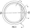
- the present invention will be described for a refrigeration compressor of the reciprocating hermetic type and comprising a motor-compressor assembly (not illustrated), including a cylinder crankcase 1 (partially illustrated in figure 4 ), which defines a cylinder 2 in whose interior a piston is axially displaced (not illustrated), through the action of a rotary or linear electric motor.
- a motor-compressor assembly (not illustrated), including a cylinder crankcase 1 (partially illustrated in figure 4 ), which defines a cylinder 2 in whose interior a piston is axially displaced (not illustrated), through the action of a rotary or linear electric motor.
- the cylinder crankcase may be constructed in any suitable metal alloy, well known in the state of the art.
- the cylinder 2 has an open end, through which the piston is housed, and an opposite end (illustrated in figure 4 ), closed by a valve plate 3, against which is seated a cylinder cap 10, usually metallic, said valve plate 3 defining, with the cylinder 2, a compression chamber C.
- the valve plate 3 is built in metal alloy, in order to operate together with at least one suction valve, not illustrated, facing the interior of the cylinder 2, and with at least one discharge valve 4 which, in the illustrated example, takes the form of a single sheet incorporating a metallic flexible blade 4a, operating in association with a respective discharge orifice 3a of the valve plate 3.
- the discharge valve may take the form of a single sheet incorporating a plurality of flexible blades, each operating in association with a respective discharge orifice provided in the valve plate 3.
- the refrigerant gas flow compressed in the interior of the compression chamber C is released from the latter, upon the opening of the discharge valve 4 by the discharge orifice 3a.
- valve plate 3 is seated on the cylinder crankcase 1, by means of an annular sealing gasket 5. Although not illustrated in the drawings, it may be further provided another annular sealing gasket located between the discharge valve 4 and the adjacent face of the valve plate 3.
- the annular sealing gasket 5 is provided with at least two diametrically opposite eccentric axial projections 5a, which are dimensioned to be fitted in respective recesses 1a provided in an opposite face of the cylinder crankcase 1, thus allowing for the correct indexing in the seating of the annular sealing gasket 5 against the cylinder crankcase 1.
- the cylinder cap 10 is seated against a face of the valve plate 3, opposed to that seated against the cylinder crankcase 1.
- the cylinder cap 10 defines, with the adjacent face of the valve plate 3, a discharge chamber 11, which maintains a selective fluid communication with the cylinder 2, through the discharge orifice 3a, upon the opening of the discharge valve 4, and a constant fluid communication with one side of the discharge of a refrigeration system to which the compressor is associated, through a discharge tube (not illustrated), which connects said discharge chamber 11 to the exterior of the compressor.
- the cylinder cap 10 takes the form of a cup with its open base seated on the valve plate 3 and defining a gas inlet 12 in fluid communication with the discharge orifice 3a, and a gas outlet 13, coupled to a discharge tube which connects said gas outlet 13 to the exterior of the compressor.
- the cylinder cap 10 is provided with an end wall 14, opposite to its open base and to the valve plate 3.
- the gas outlet 13 is provided in a chamfered region 15 of the end wall 14 and disposed facing laterally outwards of the cylinder cap 10.
- this positioning of the gas outlet 13 should not be limited to the illustrated construction.
- the gas discharge system comprises an accelerating means AM mounted in the interior of the discharge chamber 11 and fixed to at least one of the parts of cylinder cap 10 an valve plate 3, in order to receive the entire flow of refrigerant gas released by the discharge valve 4 through the discharge orifice 3a, accelerating said refrigerant gas flow and producing an instantaneous reduction in the pressure gradient between the upstream and downstream sides of the discharge valve 4, in the moment of its opening.
- AM mounted in the interior of the discharge chamber 11 and fixed to at least one of the parts of cylinder cap 10 an valve plate 3, in order to receive the entire flow of refrigerant gas released by the discharge valve 4 through the discharge orifice 3a, accelerating said refrigerant gas flow and producing an instantaneous reduction in the pressure gradient between the upstream and downstream sides of the discharge valve 4, in the moment of its opening.
- the accelerating means AM may be defined by a tubular conduct 22b of cylindrical or inverted frusto-conical shape, which projects to the interior of the discharge chamber 11, from the discharge orifice 3a of the valve plate 3, said tubular conduct 22b being dimensioned to produce the desired acceleration in the refrigerant gas flow released by the discharge orifice 3a, in the moment the discharge valve 4 opens.
- the gas discharge system may comprise a base end wall 24, seated against the valve plate 3 and provided with an inlet nozzle 22 comprising a base opening 22a, open to the discharge orifice 3a of the valve plate 3 and communicating said discharge orifice 3a to the discharge chamber 11, with the tubular conduct 22b being incorporated, in a single piece, to the base end wall 24 and defining an extension of the inlet nozzle 22 to the interior of the discharge chamber 11.
- the construction defined above allows the region of the base end wall 24, defined around the base opening 22a of the inlet nozzle 22, to define a stop for the maximum opening of the discharge valve 4, while the remaining of the base end wall 24 retains the discharge valve 4 in its position in the valve plate 3.
- annular region 22c of the base wall 24, which surrounds the base opening 22a do inlet nozzle 22, is constructed so as to be axially spaced from the valve plate 3, defining an opening stop for the flexible blade 4a of the discharge valve 4.
- said annular region 22c of the base wall 24 is provided inclined radially inward and axially inward the discharge chamber 11, defining an inclined opening stop, against which is seated the flexible blade 4a, upon the maximum opening of the discharge valve 4.
- the tubular conduct 22b of the inlet nozzle 22 has a frusto-conical configuration, having the larger base thereof open and facing the interior of the hollow body 20.
- This constructive arrangement of the inlet nozzle 22 facilitates the operation of the accelerating means AM, in order to accelerate the flow of refrigerant gas released by the discharge valve and producing an instantaneous reduction in the pressure gradient between the upstream and downstream sides of the discharge valve 4, in the moment of its opening.
- the cylinder cap 10 houses an acoustic discharge filter F having hollow body 20, which may be formed in a thermal insulating material, or in any other material, not necessarily thermally insulating, defining at least one plenum 21 in its interior and mounted, for example in an indexed manner, in the interior of the cylinder cap 10 maintaining, with the latter, a gap 30, and being seated against the valve plate 3, preventing the direct contact thereof with the internal volume of the hollow body 20.
- the plenum 21 of the hollow body 20 effectively acts as a discharge chamber and as an element of the acoustic discharge filter F.
- the discharge chamber 11 of the cylinder cap 10 acts, in this embodiment, for defining the volume of the gap 30 between the inner walls of the cylinder cap 10 and the hollow body 20.
- the assembly of the cylinder cap 10 and hollow body 20 may be carried out in order to make the gap 30 hermetic in relation to the interior of the hollow body 20 and to the exterior of the cylinder cap 10.
- the hollow body 20 of the acoustic discharge filter F is provided with the inlet nozzle 22, communicating the plenum 21 with the discharge orifice 3a of the valve plate 3, and with an outlet nozzle 23 communicating the plenum 21 with the gas outlet 13 of the cylinder cap 10.
- the base end wall 24 may incorporate a plurality of base projections facing outwards the hollow body 20, indexing the hollow body 20 in relation to the valve plate 3 and also to the annular sealing gasket 5 and to the cylinder crankcase 1.
- the hollow body 20 comprises a top end wall 25 in which is provided the outlet nozzle 23 of the hollow body 20, said outlet nozzle 23 being open to the gas outlet 13 of the cylinder cap 10.
- the outlet nozzle 23 of the hollow body 20 comprises an outer tubular projection 23a which extends outwards of a lowered region 25a of the top end wall 25 of the hollow body 20, in order to be fitted in a tubular passage 16 formed internally to the end wall 14 and which is open to the outlet nozzle 13 da cylinder cap 10.
- the outlet nozzle 13 of the cylinder cap 10 is configured to receive and secure, in its interior, by any suitable means, such as for example, threads, adhesives or brazing, a tubular connector 18 which projects outside from the outlet nozzle 13, in order to be coupled to an adjacent end of the discharge tube, not illustrated, which connects the discharge chamber 11 to the exterior of the compressor.
- the discharge system of the present invention further provides a biasing means located between the top end wall 25 of the hollow body 20 and the end wall 14 of the cylinder cap 10, in order to constantly and elastically force the hollow body 20 against the valve plate 3, minimizing the passage of the discharge gas to the interior of the cylinder cap 10, externally to the hollow body 20.
- the biasing means 40 forces the base end wall 24 against the valve plate 3, enhancing the functions of securing and limiting (stop) the base end wall 24 in relation to the discharge valve 4.
- the biasing means 40 further improves the sealing of the hollow body 20 in relation to the gap 30.
- the biasing means 40 is defined by a plate spring 41, usually in parallel rods and joined by their ends 41a, each being fitted externally to a respective top projection 25b of the top end wall 25 of the hollow body 20.
- the top end wall 25 of the hollow body 20 may incorporate a plurality of top projections facing outwards of the hollow body 20, and the end wall 14 of the cylinder cap 10 may be internally provided with an equal plurality of recesses, inside which is fitted a respective top projection of the top end wall 25, indexing, in relation to each other, the hollow body 20 and the cylinder cap 10.
- the plate spring 41 may have each of its ends fitted inside a respective top projection of the top end wall 25.
- discharge system of the present invention may be carried out independently of the constructive particularities of the cylinder cap, biasing means, etc.
- the hollow body 20 is formed of two parts 20a, 20b, one incorporating the base end wall 24 and the other incorporating the top end wall 25, said parts being seated against a common dividing wall 26 which divides the plenum 21 of the hollow body 20 into a first and into a second discharge chamber C1, C2, said dividing wall 26 presenting an opening 26a communicating both discharge chambers C1, C2.
- sealing means between the two parts 20a, 20b of the hollow body 20 and the common dividing wall 26, which sealing means may be defined in different manners, such as for example, by an adhesive film or by sealing gaskets.
- the part 20a of the hollow body 20 closer to the valve plate 3 presents an end edge 28a, facing the common dividing wall 26 and provided with at least two outer notches 29a configured to perform the function described below.
- other part 20b of the hollow body 20 has an end edge 28b facing the common dividing wall 26 and incorporating at least two axial projections 29b dimensioned to be each fitted and preferably retained into a respective outer notch 29a of the other part 20a of the hollow body 20.
- the common dividing wall 26 presents at least two radial notches 26b dimensioned to allow the passage of the axial projections 29b of the part 20b of the hollow body 20, upon closing the latter.
- the hollow body 20 may be formed in a single piece defining a single discharge chamber, or also formed in two or more parts, as illustrated, however having the dividing wall incorporated to one of said parts.
- the hollow body 20 may further present more than two discharge chambers in the interior thereof.
- the opening 26a of the dividing wall 26 receives, hermetically, at least one tube 27, which projects to the interior of the first discharge chamber C1, through a straight section 27a eccentric in relation to the inlet nozzle 22 of the hollow body 20, and into the second discharge chamber C2, through an arcuate section 27b.
- the tube 27 may be built and dimensioned in order to define an acoustic muffler.
- the tube 27 illustrated is obtained in a separate piece from the median wall 26, it should be understood that said tube may be provided in a single piece with said median wall.
- median wall 26 may be located in different positions, not necessarily horizontal or substantially horizontal, and it may even be arranged in a substantially vertical or inclined manner.
- first and the second discharge chambers C1, C2 may present equal or different volumes and also communicate with each other by more than one opening 26a or more than one tube 27.
- the first discharge chamber C1 receives, from the inlet nozzle 22 of the hollow body 20, the entire discharge flow coming from the compression chamber C, said first discharge chamber C1 maintaining a constant fluid communication with the second discharge chamber C2, through the tube 27.
- Said hollow body construction presenting two discharge chambers interconnected by a tube 27 provides, to the discharge system, an acoustic muffling function, of the volume-tube-volume type, in the interior of the cylinder cap 10.
- the discharge system of the present invention also acts as an acoustic muffler during the gas discharge in the gas compression upon operation of the compressor and also as an enhancer of the mass efficiency of the latter.
- each of the first and second discharge chambers C1, C2, as well as the determination of the dimensions of each tube 27 (length, shape, cross section) and the definition of the extension thereof projecting to the inside of each chamber in which said tube acts, are defined as a function of the thermal insulation effect to be achieved, however they can be also defined as a function of the attenuation to be achieved and of the pulsation range to be attenuated.
- the hollow body 20 may further present a plurality of discharge chambers located according to the same concept described for the two discharge chambers illustrated in the drawings.
- the tube 27 presents a first end 27c and a second end 27d which are eccentrically disposed in the first and second discharge chambers C1, C2, the first end 27c of the tube 27 being located eccentrically to the inlet nozzle 22 of the hollow body 20, and the second end 27d of the tube 27 being located spaced from the gas outlet nozzle 23 of the hollow body 20.
- the gas outlet nozzle 23 is located in direct fluid communication with the gas outlet 13 of the cylinder cap 10.
- the gas outlet nozzle 22 is located orthogonal to the gas outlet 13 of the cylinder cap 10 and connected to said gas outlet 13 by means of the tubular passage 16 provided in the end wall 14 of the cylinder cap 10.
- the illustrated tube 27 is obtained in a separate piece from the median wall 26, it should be understood that said tube may be provided in a single piece with said median wall.
- the tubular configuration of the inlet nozzle 22, projecting to the interior of the hollow body 20, by means of the tubular conduct 22b, allows the flow of refrigerant gas being compressed inside cylinder 2 to be accelerated inside said tubular projection 22, thus producing an instantaneous reduction in the pressure inside the cylinder 2, which pressure rises once again upon the approximation of the piston towards the valve plate 3.
- the instantaneous pressure drop inside the cylinder 2, upon the opening of the discharge valve 4, reduces the power loss in the discharge system, thus increasing the efficiency of the compressor. Furthermore, said instantaneous pressure drop allows reducing the pressure transients upstream and downstream of the discharge valve, at the moment the latter opens, reducing the intensity of the pulsations caused by operation of the discharge valve.
- Another important positive aspect of the proposed technical solution derives from the fact of preventing the direct contact between the compressed gas entering into the plenum 21 of the hollow body 20 and the valve plate 3, reducing the thermal exchange in the region of the cylinder cap 10.
- the proposed solution allows the usual stop of the discharge valve, which is responsible for the fixation of the latter and for limiting its maximum opening, to be defined by the base end wall 24 itself.
- the present discharge system besides leading to effective power gains, by reducing the pressure transients, as well as gains in the pumping mass of the refrigerant gas, further allows for, upon using the hollow body 20 preferably in a thermal insulating material, a substantially increased thermal insulation between the compressed gas contained in the interior of the hollow body 20 and the environment internal to the compressor housing, in relation to the discharge systems known in the state of the art.
Landscapes
- Engineering & Computer Science (AREA)
- General Engineering & Computer Science (AREA)
- Mechanical Engineering (AREA)
- Compressor (AREA)
- Compressors, Vaccum Pumps And Other Relevant Systems (AREA)
- Applications Or Details Of Rotary Compressors (AREA)
- Check Valves (AREA)
Claims (13)
- Compresseur de réfrigération ayant un système de décharge de gaz comprenant :un carter à cylindre (1) définissant un cylindre (2) qui est fermé, à une extrémité, par une plaque de soupape (3) pourvu d'au moins un orifice de décharge (3a) et définissant, avec le cylindre (2), une chambre de compression (C) ; un chapeau de cylindre (10) ayant une sortie de gaz (13) et calé contre la plaque de soupape (3) en opposition avec la chambre de compression (C) et dans la partie intérieure de laquelle est définie une chambre de décharge (11), la plaque de soupape (3) étant associée en service à au moins une soupape de décharge (4), et comprenant en outre un moyen d'accélération (AM) fixé à au moins l'une des parties du chapeau de cylindre (10) et de la plaque de soupape (3), afin de recevoir la totalité de l'écoulement du gaz réfrigérant libéré par la soupape de décharge (4) à travers l'orifice de décharge (3a), caractérisé en ce que le moyen d'accélération (AM) est monté dans la partie intérieure de la chambre de décharge (11) et défini par un conduit tubulaire (22b) qui fait saillie vers la partie intérieure de la chambre de décharge (11), de l'orifice de décharge (3a) de la plaque de soupape (3), et comprenant une paroi d'extrémité de base (24) calée contre la plaque de soupape (3) et pourvue d'une buse d'entrée (22) comprenant une ouverture de base (22a), débouchant sur l'orifice de décharge (3a) de la plaque de soupape (3) et faisant communiquer ledit orifice de décharge (3a) avec la chambre de décharge (11), ledit conduit tubulaire (22b) étant incorporé d'un seul tenant à la paroi d'extrémité de base (24) et définissant une extension de la buse d'entrée (22) vers la partie intérieure de la chambre de décharge (11), ledit moyen d'accélération (AM) accélérant ledit écoulement de gaz réfrigérant, et ledit conduit tubulaire (22b) étant dimensionné pour produire l'accélération souhaitée dans l'écoulement de gaz réfrigérant libéré par l'orifice de décharge (3a), à partir du moment où la soupape de décharge (4) s'ouvre.
- Compresseur de réfrigération selon la revendication 1, dans lequel la soupape de décharge (4) comprend au moins une lame souple (4a), caractérisé en ce que la paroi d'extrémité de base (24) comprend une région annulaire (22c), définie autour de l'ouverture de base (22a) de la buse d'entrée (22) et définissant un arrêt pour l'ouverture maximale de la lame souple (4a) de la soupape de décharge (4), tandis que le restant de la paroi d'extrémité de base (24) retient la soupape de décharge (4) dans sa position dans la plaque de soupape (3).
- Compresseur de réfrigération selon la revendication 2, caractérisé en ce que ladite région annulaire (22c) de la paroi d'extrémité de base (24), qui agit contre la lame souple (4a) de la soupape de décharge (4) est conçue pour être espacée axialement de la plaque de soupape (3), définissant un arrêt d'ouverture pour la lame souple (4a) de la soupape de décharge (4).
- Compresseur de réfrigération selon la revendication 3, caractérisé en ce que la région annulaire (22c) de la paroi de base (24) est inclinée radialement vers l'intérieur et axialement vers l'intérieur dans la partie intérieure de la chambre de décharge (11), définissant un arrêt d'ouverture incliné contre lequel est calée la lame souple (4a) lors de l'ouverture maximale de la soupape de décharge (4).
- Compresseur de réfrigération selon l'une quelconque des revendications 1 à 4, caractérisé en ce qu'il comprend un corps creux (20) définissant au moins un plénum (21) dans celui-ci et qui est monté, de manière crantée dans la partie intérieure du chapeau de cylindre (10), maintenant avec celui-ci un intervalle (30), ledit corps creux (20) comprenant la paroi d'extrémité de base (24) empêchant le contact direct de la plaque de soupape (3) avec le volume interne du corps creux (20), la buse d'entrée (22) de la paroi d'extrémité de base (24) faisant communiquer le plénum (21) avec l'orifice de décharge (3a) de la plaque de soupape (3).
- Compresseur de réfrigération selon l'une quelconque des revendications 1 à 5, dans lequel le chapeau de cylindre (10) est pourvu d'une paroi d'extrémité (14) opposée à la plaque de soupape (3), ledit système étant caractérisé en ce que le corps creux (20) comprend une paroi d'extrémité supérieure (25) dans laquelle est disposée une buse de sortie (23) du corps creux, ladite buse de sortie (23) débouchant sur la sortie de gaz (13) du chapeau de cylindre (10).
- Compresseur de réfrigération selon la revendication 6, caractérisé en ce que la buse de sortie (23) du corps creux (20) comprend une saillie tubulaire externe (23a) disposée dans la paroi d'extrémité supérieure (25) du corps creux (20), afin de s'ajuster dans un passage tubulaire (16) formé à l'intérieur de la paroi d'extrémité (14) et qui débouche sur la buse de sortie (13) du chapeau de cylindre (10).
- Compresseur de réfrigération selon la revendication 7, caractérisé en ce que la saillie tubulaire externe (23a) s'étend vers l'extérieur d'une région abaissée (25a) ménagée sur la paroi d'extrémité supérieure (25) du corps creux (20).
- Compresseur de réfrigération selon l'une quelconque des revendications 6 à 8, caractérisé en ce qu'il comprend un moyen de sollicitation (40), situé entre la paroi d'extrémité supérieure (25) et la paroi d'extrémité (14) du chapeau de cylindre (10) et refoule de manière élastique le corps creux (20) contre la plaque de soupape (3).
- Compresseur de réfrigération selon la revendication 9, caractérisé en ce que le moyen de sollicitation (40) est défini par un ressort à lames (41).
- Compresseur de réfrigération selon la revendication 10, caractérisé en ce que la paroi d'extrémité supérieure (25) incorpore une pluralité de saillies supérieures (25b) tournées vers l'extérieur du corps creux (20), le ressort à lames (41) présentant des extrémités opposées, chacune étant ajustée dans une saillie supérieure respective (25b) de la paroi d'extrémité supérieure (25) du corps creux (20).
- Compresseur de réfrigération selon l'une quelconque des revendications 5 à 11, caractérisé en ce que le corps creux (20) est formé en deux parties (20a, 20b), l'une incorporant la paroi d'extrémité de base (24) et l'autre incorporant la paroi d'extrémité supérieure (25), lesdites parties étant calées contre une paroi de division commune (26) qui divise le plénum (21) du corps creux (20) en une première et une seconde chambre de décharge (C1, C2), ladite paroi de division (26) présentant au moins une ouverture (26a) communiquant avec les deux chambres de décharge (C1, C2).
- Compresseur de réfrigération selon la revendication 12, caractérisé en ce que l'ouverture (26a) de la paroi de division (26) comprend au moins un tube (27) faisant saillie vers la partie intérieure de la première chambre de décharge (C1), à travers une section droite (27a) excentrique par rapport à la buse d'entrée (22), et vers la partie intérieure de la seconde chambre de décharge (C2), à travers une section arquée (27b) définissant un amortisseur acoustique.
Applications Claiming Priority (2)
| Application Number | Priority Date | Filing Date | Title |
|---|---|---|---|
| BR102012025279-1A BR102012025279B1 (pt) | 2012-10-03 | 2012-10-03 | Compressor de refrigeração tendo um sistema de descarga de gás |
| PCT/BR2013/000393 WO2014053039A1 (fr) | 2012-10-03 | 2013-08-02 | Système de refoulement de gaz pour compresseur frigorifique et compresseur frigorifique |
Publications (2)
| Publication Number | Publication Date |
|---|---|
| EP2912314A1 EP2912314A1 (fr) | 2015-09-02 |
| EP2912314B1 true EP2912314B1 (fr) | 2017-09-13 |
Family
ID=49596016
Family Applications (1)
| Application Number | Title | Priority Date | Filing Date |
|---|---|---|---|
| EP13792243.1A Not-in-force EP2912314B1 (fr) | 2012-10-03 | 2013-10-02 | Système de refoulement de gaz pour compresseur frigorifique et compresseur frigorifique |
Country Status (10)
| Country | Link |
|---|---|
| US (1) | US10227975B2 (fr) |
| EP (1) | EP2912314B1 (fr) |
| JP (1) | JP6375299B2 (fr) |
| KR (1) | KR20150085812A (fr) |
| CN (1) | CN104781553B (fr) |
| AU (1) | AU2013327352A1 (fr) |
| BR (1) | BR102012025279B1 (fr) |
| MX (1) | MX355169B (fr) |
| NZ (1) | NZ706403A (fr) |
| WO (1) | WO2014053039A1 (fr) |
Cited By (1)
| Publication number | Priority date | Publication date | Assignee | Title |
|---|---|---|---|---|
| WO2020223293A1 (fr) | 2019-04-29 | 2020-11-05 | Gast Manufacturing, Inc. | Dispositif de réduction sonore pour pompes et compresseurs à piston oscillant |
Families Citing this family (7)
| Publication number | Priority date | Publication date | Assignee | Title |
|---|---|---|---|---|
| DE102015205059A1 (de) | 2015-03-20 | 2016-09-22 | Continental Teves Ag & Co. Ohg | Motorpumpenaggregat mit einer einzelnen elastischen Membran |
| KR102238334B1 (ko) * | 2016-05-03 | 2021-04-09 | 엘지전자 주식회사 | 리니어 압축기 |
| FR3058766B1 (fr) * | 2016-11-16 | 2018-12-14 | Atlas Copco Crepelle S.A.S. | Compresseur alternatif |
| BR102017013190A2 (pt) * | 2017-06-19 | 2019-01-15 | Whirlpool S.A. | estrutura para montagem de válvula tipo palheta |
| IT201800002414A1 (it) * | 2018-02-05 | 2019-08-05 | Lodovico Parmegiani | Dispositivo per il congelamento di tessuto adiposo |
| CN108953116A (zh) * | 2018-08-15 | 2018-12-07 | 蚌埠艾普压缩机制造有限公司 | 一种加氢站氢气压缩机可拆洗高效冷却器 |
| DE102020116690A1 (de) * | 2020-06-24 | 2021-12-30 | Bitzer Kühlmaschinenbau Gmbh | Kältemittelverdichter |
Family Cites Families (10)
| Publication number | Priority date | Publication date | Assignee | Title |
|---|---|---|---|---|
| JPS61207884A (ja) * | 1985-03-12 | 1986-09-16 | Diesel Kiki Co Ltd | 圧縮機の脈動低減機構 |
| BR8905898A (pt) * | 1989-11-08 | 1991-05-14 | Brasil Compressores Sa | Valvula de descarga para compressor hermetico |
| JP3205122B2 (ja) * | 1993-05-19 | 2001-09-04 | 株式会社日立製作所 | 密閉形電動圧縮機 |
| DE19912926A1 (de) | 1999-03-22 | 2000-09-28 | Bock Gmbh & Co Kaeltemaschinen | Kolbenverdichter für Kältemittel |
| AT8985U1 (de) | 2005-03-31 | 2007-03-15 | Acc Austria Gmbh | Kältemittelverdichter |
| AT8477U1 (de) | 2005-03-31 | 2006-08-15 | Acc Austria Gmbh | Kältemittelverdichter |
| AT8401U1 (de) * | 2005-03-31 | 2006-07-15 | Acc Austria Gmbh | Kältemittelverdichter |
| BRPI0505717B1 (pt) * | 2005-12-16 | 2020-03-10 | Embraco Indústria De Compressores E Soluções Em Refrigeração Ltda | Compressor hermético com isolamento térmico interno |
| BRPI0705357A2 (pt) * | 2007-12-26 | 2009-08-25 | Whirlpool Sa | sistema para atenuação de pulsação na descarga de gás em um compressor de refrigeração |
| BRPI0803457B1 (pt) * | 2008-09-05 | 2020-11-10 | Embraco Indústria De Compressores E Soluções Em Refrigeração Ltda | arranjo de sucção para compressor hermético de refrigeração |
-
2012
- 2012-10-03 BR BR102012025279-1A patent/BR102012025279B1/pt not_active IP Right Cessation
-
2013
- 2013-08-02 CN CN201380058925.5A patent/CN104781553B/zh not_active Expired - Fee Related
- 2013-08-02 NZ NZ706403A patent/NZ706403A/en not_active IP Right Cessation
- 2013-08-02 WO PCT/BR2013/000393 patent/WO2014053039A1/fr not_active Ceased
- 2013-08-02 US US14/432,883 patent/US10227975B2/en active Active
- 2013-08-02 AU AU2013327352A patent/AU2013327352A1/en not_active Abandoned
- 2013-10-02 MX MX2015004343A patent/MX355169B/es active IP Right Grant
- 2013-10-02 KR KR1020157011605A patent/KR20150085812A/ko not_active Withdrawn
- 2013-10-02 EP EP13792243.1A patent/EP2912314B1/fr not_active Not-in-force
- 2013-10-02 JP JP2015534889A patent/JP6375299B2/ja not_active Expired - Fee Related
Non-Patent Citations (1)
| Title |
|---|
| None * |
Cited By (2)
| Publication number | Priority date | Publication date | Assignee | Title |
|---|---|---|---|---|
| WO2020223293A1 (fr) | 2019-04-29 | 2020-11-05 | Gast Manufacturing, Inc. | Dispositif de réduction sonore pour pompes et compresseurs à piston oscillant |
| EP3963207B1 (fr) * | 2019-04-29 | 2025-09-03 | Gast Manufacturing, Inc. | Dispositif de réduction sonore pour pompes et compresseurs à piston oscillant |
Also Published As
| Publication number | Publication date |
|---|---|
| JP6375299B2 (ja) | 2018-08-15 |
| MX2015004343A (es) | 2015-06-10 |
| CN104781553B (zh) | 2017-07-07 |
| WO2014053039A1 (fr) | 2014-04-10 |
| NZ706403A (en) | 2017-12-22 |
| MX355169B (es) | 2018-04-06 |
| US10227975B2 (en) | 2019-03-12 |
| AU2013327352A1 (en) | 2015-04-16 |
| JP2015530519A (ja) | 2015-10-15 |
| AU2013327352A9 (en) | 2016-08-25 |
| EP2912314A1 (fr) | 2015-09-02 |
| BR102012025279A2 (pt) | 2014-08-19 |
| CN104781553A (zh) | 2015-07-15 |
| KR20150085812A (ko) | 2015-07-24 |
| BR102012025279B1 (pt) | 2021-09-21 |
| US20150275884A1 (en) | 2015-10-01 |
| WO2014053039A8 (fr) | 2016-08-04 |
Similar Documents
| Publication | Publication Date | Title |
|---|---|---|
| EP2912314B1 (fr) | Système de refoulement de gaz pour compresseur frigorifique et compresseur frigorifique | |
| EP2912315B1 (fr) | Système d'isolation thermique pour le refoulement de gaz dans un compresseur frigorifique | |
| CN102119275B (zh) | 用于封闭式压缩机的排出阀装置 | |
| JP2015530519A6 (ja) | 冷凍圧縮機用ガス排気システムおよび冷凍圧縮機 | |
| KR20140060144A (ko) | 압축기의 흡입머플러 | |
| US4979879A (en) | Discharge system for rolling piston rotary compressor | |
| EP3184822B1 (fr) | Compresseur rotatif et dispositif de cycle de réfrigération | |
| JP4888754B2 (ja) | 密閉型コンプレッサ用バルブ装置 | |
| KR20150074338A (ko) | 압축기 및 맥동저감 밸브조립체 | |
| US20120128509A1 (en) | Reciprocating Compressor | |
| KR100958192B1 (ko) | 밀폐형 압축기의 헤드커버 및 이를 사용한 작동유체토출장치 | |
| CN115434889B (zh) | 压缩机 | |
| KR101576227B1 (ko) | 밀폐형 압축기용 밸브 조립체 모듈 | |
| CN208330652U (zh) | 一种半封闭中间补气双缸活塞制冷压缩机 | |
| US20220163026A1 (en) | Suction muffler for reciprocating compressor | |
| KR20180037538A (ko) | 토출 머플러 및 이를 포함하는 압축기 | |
| KR100789335B1 (ko) | 소형 밀폐형 압축기용 흡입 및 배출 밸브 장치 | |
| KR20040104760A (ko) | 리니어 압축기의 소음저감구조 |
Legal Events
| Date | Code | Title | Description |
|---|---|---|---|
| PUAI | Public reference made under article 153(3) epc to a published international application that has entered the european phase |
Free format text: ORIGINAL CODE: 0009012 |
|
| 17P | Request for examination filed |
Effective date: 20150504 |
|
| AK | Designated contracting states |
Kind code of ref document: A1 Designated state(s): AL AT BE BG CH CY CZ DE DK EE ES FI FR GB GR HR HU IE IS IT LI LT LU LV MC MK MT NL NO PL PT RO RS SE SI SK SM TR |
|
| AX | Request for extension of the european patent |
Extension state: BA ME |
|
| DAX | Request for extension of the european patent (deleted) | ||
| RIN1 | Information on inventor provided before grant (corrected) |
Inventor name: WAJCZYK, TALITA Inventor name: LILIE, DIETMAR ERICH BERNHARD |
|
| GRAP | Despatch of communication of intention to grant a patent |
Free format text: ORIGINAL CODE: EPIDOSNIGR1 |
|
| INTG | Intention to grant announced |
Effective date: 20170323 |
|
| GRAS | Grant fee paid |
Free format text: ORIGINAL CODE: EPIDOSNIGR3 |
|
| GRAA | (expected) grant |
Free format text: ORIGINAL CODE: 0009210 |
|
| AK | Designated contracting states |
Kind code of ref document: B1 Designated state(s): AL AT BE BG CH CY CZ DE DK EE ES FI FR GB GR HR HU IE IS IT LI LT LU LV MC MK MT NL NO PL PT RO RS SE SI SK SM TR |
|
| REG | Reference to a national code |
Ref country code: GB Ref legal event code: FG4D |
|
| REG | Reference to a national code |
Ref country code: CH Ref legal event code: EP |
|
| REG | Reference to a national code |
Ref country code: IE Ref legal event code: FG4D |
|
| REG | Reference to a national code |
Ref country code: AT Ref legal event code: REF Ref document number: 928433 Country of ref document: AT Kind code of ref document: T Effective date: 20171015 |
|
| REG | Reference to a national code |
Ref country code: DE Ref legal event code: R096 Ref document number: 602013026641 Country of ref document: DE |
|
| REG | Reference to a national code |
Ref country code: NL Ref legal event code: MP Effective date: 20170913 |
|
| REG | Reference to a national code |
Ref country code: LT Ref legal event code: MG4D |
|
| PG25 | Lapsed in a contracting state [announced via postgrant information from national office to epo] |
Ref country code: SE Free format text: LAPSE BECAUSE OF FAILURE TO SUBMIT A TRANSLATION OF THE DESCRIPTION OR TO PAY THE FEE WITHIN THE PRESCRIBED TIME-LIMIT Effective date: 20170913 Ref country code: HR Free format text: LAPSE BECAUSE OF FAILURE TO SUBMIT A TRANSLATION OF THE DESCRIPTION OR TO PAY THE FEE WITHIN THE PRESCRIBED TIME-LIMIT Effective date: 20170913 Ref country code: LT Free format text: LAPSE BECAUSE OF FAILURE TO SUBMIT A TRANSLATION OF THE DESCRIPTION OR TO PAY THE FEE WITHIN THE PRESCRIBED TIME-LIMIT Effective date: 20170913 Ref country code: FI Free format text: LAPSE BECAUSE OF FAILURE TO SUBMIT A TRANSLATION OF THE DESCRIPTION OR TO PAY THE FEE WITHIN THE PRESCRIBED TIME-LIMIT Effective date: 20170913 Ref country code: NO Free format text: LAPSE BECAUSE OF FAILURE TO SUBMIT A TRANSLATION OF THE DESCRIPTION OR TO PAY THE FEE WITHIN THE PRESCRIBED TIME-LIMIT Effective date: 20171213 |
|
| REG | Reference to a national code |
Ref country code: AT Ref legal event code: MK05 Ref document number: 928433 Country of ref document: AT Kind code of ref document: T Effective date: 20170913 |
|
| PG25 | Lapsed in a contracting state [announced via postgrant information from national office to epo] |
Ref country code: RS Free format text: LAPSE BECAUSE OF FAILURE TO SUBMIT A TRANSLATION OF THE DESCRIPTION OR TO PAY THE FEE WITHIN THE PRESCRIBED TIME-LIMIT Effective date: 20170913 Ref country code: LV Free format text: LAPSE BECAUSE OF FAILURE TO SUBMIT A TRANSLATION OF THE DESCRIPTION OR TO PAY THE FEE WITHIN THE PRESCRIBED TIME-LIMIT Effective date: 20170913 Ref country code: BG Free format text: LAPSE BECAUSE OF FAILURE TO SUBMIT A TRANSLATION OF THE DESCRIPTION OR TO PAY THE FEE WITHIN THE PRESCRIBED TIME-LIMIT Effective date: 20171213 Ref country code: ES Free format text: LAPSE BECAUSE OF FAILURE TO SUBMIT A TRANSLATION OF THE DESCRIPTION OR TO PAY THE FEE WITHIN THE PRESCRIBED TIME-LIMIT Effective date: 20170913 |
|
| PG25 | Lapsed in a contracting state [announced via postgrant information from national office to epo] |
Ref country code: NL Free format text: LAPSE BECAUSE OF FAILURE TO SUBMIT A TRANSLATION OF THE DESCRIPTION OR TO PAY THE FEE WITHIN THE PRESCRIBED TIME-LIMIT Effective date: 20170913 |
|
| PG25 | Lapsed in a contracting state [announced via postgrant information from national office to epo] |
Ref country code: CZ Free format text: LAPSE BECAUSE OF FAILURE TO SUBMIT A TRANSLATION OF THE DESCRIPTION OR TO PAY THE FEE WITHIN THE PRESCRIBED TIME-LIMIT Effective date: 20170913 Ref country code: PL Free format text: LAPSE BECAUSE OF FAILURE TO SUBMIT A TRANSLATION OF THE DESCRIPTION OR TO PAY THE FEE WITHIN THE PRESCRIBED TIME-LIMIT Effective date: 20170913 Ref country code: RO Free format text: LAPSE BECAUSE OF FAILURE TO SUBMIT A TRANSLATION OF THE DESCRIPTION OR TO PAY THE FEE WITHIN THE PRESCRIBED TIME-LIMIT Effective date: 20170913 |
|
| PG25 | Lapsed in a contracting state [announced via postgrant information from national office to epo] |
Ref country code: IS Free format text: LAPSE BECAUSE OF FAILURE TO SUBMIT A TRANSLATION OF THE DESCRIPTION OR TO PAY THE FEE WITHIN THE PRESCRIBED TIME-LIMIT Effective date: 20180113 Ref country code: SM Free format text: LAPSE BECAUSE OF FAILURE TO SUBMIT A TRANSLATION OF THE DESCRIPTION OR TO PAY THE FEE WITHIN THE PRESCRIBED TIME-LIMIT Effective date: 20170913 Ref country code: AT Free format text: LAPSE BECAUSE OF FAILURE TO SUBMIT A TRANSLATION OF THE DESCRIPTION OR TO PAY THE FEE WITHIN THE PRESCRIBED TIME-LIMIT Effective date: 20170913 Ref country code: EE Free format text: LAPSE BECAUSE OF FAILURE TO SUBMIT A TRANSLATION OF THE DESCRIPTION OR TO PAY THE FEE WITHIN THE PRESCRIBED TIME-LIMIT Effective date: 20170913 Ref country code: SK Free format text: LAPSE BECAUSE OF FAILURE TO SUBMIT A TRANSLATION OF THE DESCRIPTION OR TO PAY THE FEE WITHIN THE PRESCRIBED TIME-LIMIT Effective date: 20170913 |
|
| REG | Reference to a national code |
Ref country code: CH Ref legal event code: PL |
|
| REG | Reference to a national code |
Ref country code: DE Ref legal event code: R097 Ref document number: 602013026641 Country of ref document: DE |
|
| PG25 | Lapsed in a contracting state [announced via postgrant information from national office to epo] |
Ref country code: MC Free format text: LAPSE BECAUSE OF FAILURE TO SUBMIT A TRANSLATION OF THE DESCRIPTION OR TO PAY THE FEE WITHIN THE PRESCRIBED TIME-LIMIT Effective date: 20170913 |
|
| PLBE | No opposition filed within time limit |
Free format text: ORIGINAL CODE: 0009261 |
|
| STAA | Information on the status of an ep patent application or granted ep patent |
Free format text: STATUS: NO OPPOSITION FILED WITHIN TIME LIMIT |
|
| REG | Reference to a national code |
Ref country code: IE Ref legal event code: MM4A |
|
| REG | Reference to a national code |
Ref country code: FR Ref legal event code: ST Effective date: 20180629 |
|
| PG25 | Lapsed in a contracting state [announced via postgrant information from national office to epo] |
Ref country code: CH Free format text: LAPSE BECAUSE OF NON-PAYMENT OF DUE FEES Effective date: 20171031 Ref country code: DK Free format text: LAPSE BECAUSE OF FAILURE TO SUBMIT A TRANSLATION OF THE DESCRIPTION OR TO PAY THE FEE WITHIN THE PRESCRIBED TIME-LIMIT Effective date: 20170913 Ref country code: LI Free format text: LAPSE BECAUSE OF NON-PAYMENT OF DUE FEES Effective date: 20171031 Ref country code: LU Free format text: LAPSE BECAUSE OF NON-PAYMENT OF DUE FEES Effective date: 20171002 |
|
| 26N | No opposition filed |
Effective date: 20180614 |
|
| REG | Reference to a national code |
Ref country code: BE Ref legal event code: MM Effective date: 20171031 |
|
| GBPC | Gb: european patent ceased through non-payment of renewal fee |
Effective date: 20171213 |
|
| PG25 | Lapsed in a contracting state [announced via postgrant information from national office to epo] |
Ref country code: BE Free format text: LAPSE BECAUSE OF NON-PAYMENT OF DUE FEES Effective date: 20171031 Ref country code: FR Free format text: LAPSE BECAUSE OF NON-PAYMENT OF DUE FEES Effective date: 20171113 |
|
| PG25 | Lapsed in a contracting state [announced via postgrant information from national office to epo] |
Ref country code: MT Free format text: LAPSE BECAUSE OF NON-PAYMENT OF DUE FEES Effective date: 20171002 |
|
| PG25 | Lapsed in a contracting state [announced via postgrant information from national office to epo] |
Ref country code: IE Free format text: LAPSE BECAUSE OF NON-PAYMENT OF DUE FEES Effective date: 20171002 |
|
| PG25 | Lapsed in a contracting state [announced via postgrant information from national office to epo] |
Ref country code: SI Free format text: LAPSE BECAUSE OF FAILURE TO SUBMIT A TRANSLATION OF THE DESCRIPTION OR TO PAY THE FEE WITHIN THE PRESCRIBED TIME-LIMIT Effective date: 20170913 Ref country code: GB Free format text: LAPSE BECAUSE OF NON-PAYMENT OF DUE FEES Effective date: 20171213 |
|
| REG | Reference to a national code |
Ref country code: DE Ref legal event code: R081 Ref document number: 602013026641 Country of ref document: DE Owner name: EMBRACO INDUSTRIA DE COMPRESSORES E SOLUCOES E, BR Free format text: FORMER OWNER: WHIRLPOOL S.A., SAO PAULO, BR |
|
| PG25 | Lapsed in a contracting state [announced via postgrant information from national office to epo] |
Ref country code: HU Free format text: LAPSE BECAUSE OF FAILURE TO SUBMIT A TRANSLATION OF THE DESCRIPTION OR TO PAY THE FEE WITHIN THE PRESCRIBED TIME-LIMIT; INVALID AB INITIO Effective date: 20131002 |
|
| PG25 | Lapsed in a contracting state [announced via postgrant information from national office to epo] |
Ref country code: CY Free format text: LAPSE BECAUSE OF FAILURE TO SUBMIT A TRANSLATION OF THE DESCRIPTION OR TO PAY THE FEE WITHIN THE PRESCRIBED TIME-LIMIT Effective date: 20170913 |
|
| PG25 | Lapsed in a contracting state [announced via postgrant information from national office to epo] |
Ref country code: MK Free format text: LAPSE BECAUSE OF FAILURE TO SUBMIT A TRANSLATION OF THE DESCRIPTION OR TO PAY THE FEE WITHIN THE PRESCRIBED TIME-LIMIT Effective date: 20170913 |
|
| PG25 | Lapsed in a contracting state [announced via postgrant information from national office to epo] |
Ref country code: TR Free format text: LAPSE BECAUSE OF FAILURE TO SUBMIT A TRANSLATION OF THE DESCRIPTION OR TO PAY THE FEE WITHIN THE PRESCRIBED TIME-LIMIT Effective date: 20170913 |
|
| PG25 | Lapsed in a contracting state [announced via postgrant information from national office to epo] |
Ref country code: PT Free format text: LAPSE BECAUSE OF FAILURE TO SUBMIT A TRANSLATION OF THE DESCRIPTION OR TO PAY THE FEE WITHIN THE PRESCRIBED TIME-LIMIT Effective date: 20170913 |
|
| PG25 | Lapsed in a contracting state [announced via postgrant information from national office to epo] |
Ref country code: GR Free format text: LAPSE BECAUSE OF FAILURE TO SUBMIT A TRANSLATION OF THE DESCRIPTION OR TO PAY THE FEE WITHIN THE PRESCRIBED TIME-LIMIT Effective date: 20170913 |
|
| PG25 | Lapsed in a contracting state [announced via postgrant information from national office to epo] |
Ref country code: AL Free format text: LAPSE BECAUSE OF FAILURE TO SUBMIT A TRANSLATION OF THE DESCRIPTION OR TO PAY THE FEE WITHIN THE PRESCRIBED TIME-LIMIT Effective date: 20170913 |
|
| PGFP | Annual fee paid to national office [announced via postgrant information from national office to epo] |
Ref country code: IT Payment date: 20221026 Year of fee payment: 10 Ref country code: DE Payment date: 20221019 Year of fee payment: 10 |
|
| REG | Reference to a national code |
Ref country code: DE Ref legal event code: R119 Ref document number: 602013026641 Country of ref document: DE |
|
| PG25 | Lapsed in a contracting state [announced via postgrant information from national office to epo] |
Ref country code: DE Free format text: LAPSE BECAUSE OF NON-PAYMENT OF DUE FEES Effective date: 20240501 |
|
| PG25 | Lapsed in a contracting state [announced via postgrant information from national office to epo] |
Ref country code: IT Free format text: LAPSE BECAUSE OF NON-PAYMENT OF DUE FEES Effective date: 20231002 |
|
| PG25 | Lapsed in a contracting state [announced via postgrant information from national office to epo] |
Ref country code: IT Free format text: LAPSE BECAUSE OF NON-PAYMENT OF DUE FEES Effective date: 20231002 |