EP2912355B1 - Herausziehbare ventilgruppe mit verbessertem obturator - Google Patents
Herausziehbare ventilgruppe mit verbessertem obturator Download PDFInfo
- Publication number
- EP2912355B1 EP2912355B1 EP13801735.5A EP13801735A EP2912355B1 EP 2912355 B1 EP2912355 B1 EP 2912355B1 EP 13801735 A EP13801735 A EP 13801735A EP 2912355 B1 EP2912355 B1 EP 2912355B1
- Authority
- EP
- European Patent Office
- Prior art keywords
- valve group
- obturator
- duct
- active portion
- cooling liquid
- Prior art date
- Legal status (The legal status is an assumption and is not a legal conclusion. Google has not performed a legal analysis and makes no representation as to the accuracy of the status listed.)
- Active
Links
Images


Classifications
-
- F—MECHANICAL ENGINEERING; LIGHTING; HEATING; WEAPONS; BLASTING
- F04—POSITIVE - DISPLACEMENT MACHINES FOR LIQUIDS; PUMPS FOR LIQUIDS OR ELASTIC FLUIDS
- F04D—NON-POSITIVE-DISPLACEMENT PUMPS
- F04D29/00—Details, component parts, or accessories
- F04D29/40—Casings; Connections of working fluid
- F04D29/42—Casings; Connections of working fluid for radial or helico-centrifugal pumps
- F04D29/426—Casings; Connections of working fluid for radial or helico-centrifugal pumps especially adapted for liquid pumps
-
- F—MECHANICAL ENGINEERING; LIGHTING; HEATING; WEAPONS; BLASTING
- F04—POSITIVE - DISPLACEMENT MACHINES FOR LIQUIDS; PUMPS FOR LIQUIDS OR ELASTIC FLUIDS
- F04D—NON-POSITIVE-DISPLACEMENT PUMPS
- F04D15/00—Control, e.g. regulation, of pumps, pumping installations or systems
- F04D15/0005—Control, e.g. regulation, of pumps, pumping installations or systems by using valves
- F04D15/0022—Control, e.g. regulation, of pumps, pumping installations or systems by using valves throttling valves or valves varying the pump inlet opening or the outlet opening
-
- F—MECHANICAL ENGINEERING; LIGHTING; HEATING; WEAPONS; BLASTING
- F16—ENGINEERING ELEMENTS AND UNITS; GENERAL MEASURES FOR PRODUCING AND MAINTAINING EFFECTIVE FUNCTIONING OF MACHINES OR INSTALLATIONS; THERMAL INSULATION IN GENERAL
- F16K—VALVES; TAPS; COCKS; ACTUATING-FLOATS; DEVICES FOR VENTING OR AERATING
- F16K1/00—Lift valves or globe valves, i.e. cut-off apparatus with closure members having at least a component of their opening and closing motion perpendicular to the closing faces
- F16K1/16—Lift valves or globe valves, i.e. cut-off apparatus with closure members having at least a component of their opening and closing motion perpendicular to the closing faces with pivoted closure-members
- F16K1/18—Lift valves or globe valves, i.e. cut-off apparatus with closure members having at least a component of their opening and closing motion perpendicular to the closing faces with pivoted closure-members with pivoted discs or flaps
- F16K1/20—Lift valves or globe valves, i.e. cut-off apparatus with closure members having at least a component of their opening and closing motion perpendicular to the closing faces with pivoted closure-members with pivoted discs or flaps with axis of rotation arranged externally of valve member
- F16K1/2042—Special features or arrangements of the sealing
- F16K1/205—Special features or arrangements of the sealing the sealing being arranged on the valve member
-
- F—MECHANICAL ENGINEERING; LIGHTING; HEATING; WEAPONS; BLASTING
- F16—ENGINEERING ELEMENTS AND UNITS; GENERAL MEASURES FOR PRODUCING AND MAINTAINING EFFECTIVE FUNCTIONING OF MACHINES OR INSTALLATIONS; THERMAL INSULATION IN GENERAL
- F16K—VALVES; TAPS; COCKS; ACTUATING-FLOATS; DEVICES FOR VENTING OR AERATING
- F16K1/00—Lift valves or globe valves, i.e. cut-off apparatus with closure members having at least a component of their opening and closing motion perpendicular to the closing faces
- F16K1/24—Lift valves or globe valves, i.e. cut-off apparatus with closure members having at least a component of their opening and closing motion perpendicular to the closing faces with valve members that, on opening of the valve, are initially lifted from the seat and next are turned around an axis parallel to the seat
-
- F—MECHANICAL ENGINEERING; LIGHTING; HEATING; WEAPONS; BLASTING
- F16—ENGINEERING ELEMENTS AND UNITS; GENERAL MEASURES FOR PRODUCING AND MAINTAINING EFFECTIVE FUNCTIONING OF MACHINES OR INSTALLATIONS; THERMAL INSULATION IN GENERAL
- F16K—VALVES; TAPS; COCKS; ACTUATING-FLOATS; DEVICES FOR VENTING OR AERATING
- F16K27/00—Construction of housing; Use of materials therefor
- F16K27/02—Construction of housing; Use of materials therefor of lift valves
- F16K27/0209—Check valves or pivoted valves
Definitions
- the present invention relates to a valve group for a pump of a cooling circuit, in particular for vehicles, such as motor vehicles or motor cycles.
- cooling pumps are illustrated in the documents EP-A1-1503083 , PCT/IT2009/000269 , PCT/IB2011/050256 in the name of the Applicant.
- the obturator positioned downstream of the rotor assumes an essential role; moreover, within the sphere of the document PCT/IB2011/050256 the fact that the valve group is in the form of an extractable cartridge from the pump also acquires particular importance.
- the purpose of the present invention is to make a valve group comprising an obturator, particularly suitable for use in the sphere of a cooling pump, minimising to the point of eliminating the undesirable transit of cooling liquid.
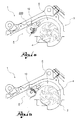
- reference numeral 1 globally denotes a pump for a cooling circuit, in particular for vehicles, comprising a pump body 2 and a rotor 4 housed in the pump body 2, for example having a substantially circular shape.
- the pump 1 is mechanically operated.
- the pump body 2 is connectable to the cooling circuit of the motor, and in particular is connectable to a section of suction circuit, upstream, from which the liquid is aspirated, and a delivery section of circuit, downstream, to which the pressurised liquid is fed, towards the motor.
- the rotor 4 placed in rotation around a rotor rotation axis, is suitable for aspirating the liquid from the suction section and sending it in pressurised form to the delivery section.
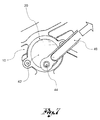
- the pump body 2 Downstream of the rotor, the pump body 2 has a delivery chamber 6, preferably having a volute profile, and a delivery duct 8, which extends from the delivery chamber 6.
- the delivery chamber 6 and the delivery duct 8 have not any further openings towards further ducts, except for the opening of the delivery duct towards the downstream section of the cooling circuit.
- the pump 1 comprises a valve group 10, to limit on command the passage of the liquid from the delivery chamber 6 to the delivery duct 8.
- valve group 10 is suitable for being positioned in an open configuration, in which the transit of liquid is permitted and in a closed configuration in which it obstructs the passage from the delivery chamber 6 to the delivery duct 8, limiting or preferably eliminating or preventing the transit of liquid from the delivery chamber 6 to the delivery duct 8.
- the valve group 10 when the valve group 10 is in the closed configuration, the delivery chamber 6 is closed and the liquid remains inside it, stirred by the rotor in rotation.
- valve group 10 permits the transit of a predefined quantity of liquid from the delivery chamber 6 to the delivery duct 8.
- the valve group 10 permits the transit of the greatest quantity possible of cooling liquid.
- the pump body 2 has a housing compartment 200 and the valve group 10 is insertable in the housing compartment and extractable therefrom, being provided with a cartridge structure.
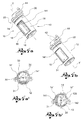
- valve group 10 comprises a valve body 12, formed of an element elongated along a rotation axis Y-Y, preferably of a cylindrical shape, provided with a through duct 14.
- valve group 10 is structured so as to delimit by its presence a passage through which the cooling liquid is suitable to flow.
- the duct 14 is delimited by a plate 16 on the bottom,, by side walls 18, projecting axially from the plate 16, internally moulded so as to facilitate the flow of cooling liquid therein, for example by means of the Venturi effect, and by a tubular head 20 which surmounts and joins the side walls 18 on the side opposite the plate 16.
- the duct 14 has in addition, at least one access mouth 14' through which the cooling liquid accesses the inside of the valve group 10 and at least one exit mouth 14" through which the cooling liquid exits from the valve group 10.
- the at least one access mouth 14' and the at least one exit mouth 14" are respectively delimited by an access rim 141 and an exit rim 142.
- valve body 12 is made in a single piece; in further embodiments, the valve body 12 is made in two reciprocally engageable parts.
- valve body 12 is provided with external seals, for example in the form of beads 22 housed in grooves provided on the outer surfaces of the side wall 18, and/or in the form of an O-ring 24 housed in a groove provided externally to the head 20 or to the plate 16.
- the valve group 10 comprises an obturator 30 housed in the duct 14 of the valve body 12 so as to swivel around the rotation axis Y-Y, so as to obstruct, in a closed position, the passage of liquid through the duct 14.
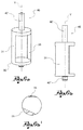
- the obturator 30 comprises an active portion 31 rotating in an offset manner in relation to the rotation axis Y-Y, suitable for assuming an open position in which it permits the passage of the liquid and a closed position in which obstructs the passage.
- the active portion 31 is suitable to sealingly engage the valve body 12 so as to stop the passage of the cooling liquid.
- the active portion 31 is suitable to engage the at least one access mouth 14' or the at least one exit mouth 14" so as to prevent the passage of cooling liquid between the delivery chamber 6 and delivery duct 8.
- the active portion 31 is suitable to engage the at least one access mouth 14', thus blocking the flow of cooling liquid inside the duct 14.
- said sealed engagement between the active portion 31 and valve body 12 is achieved by means of a gasket 50, comprised in the valve group 12.
- said gasket 50 is placed on the obturator 30 and in particular on the active portion 31 thereof.
- said gasket 50 is fitted on the obturator 30, in particular on the active portion 31 thereof.
- said gasket 50 is heat welded on to the obturator 30, specifically on the active portion 31 thereof; in some embodiments the active portion 31 comprises special hollows 310 suitable to contain a part of said gasket 50 so that it remains in position over time even after numerous functioning cycles.
- said gasket 50 is instead placed inside the valve body 12 towards the inside of the duct 14, preferably, at the access mouth 14' and/or the exit mouth 14", specifically, at the access rim 141 and/or the exit rim 142.
- the shapes of the obturator 30, of the active portion 31, just as that of the duct 14 and specifically that of the at least one access mouth 14' and/or of the at least one exit mouth 14" are designed so as to favour said reciprocal engagement of the parts.
- the active portion 31 is a substantially complementary shape to the at least one access mouth 14' or the at least one exit mouth 14".
- the active portion 31 has greater dimensions than the free transit space of the at least one access mouth 14' or of the at least one exit mouth 14", so that when positioned in front of one of them it prevents the passage of liquid.
- the obturator 31 has dimensions such as to guarantee engagement with the valve group 12 and the relative gasket 50.
- the active portion 31 when rotated into the open position, is positioned in such a way as to favour the movement of the cooling liquid, for example exploiting the Venturi effect.
- the active portion 31 has a variable cross-section, so as not to influence, when placed in the open position, the flow of cooling liquid inside the duct 14.
- the active portion has a variable shape.
- the active portion 31 in fact identifies, preferably substantially parallel to the rotation axis Y-Y, a high rim 311 and a sharp rim 312, wherein the high rim 311 has a greater thickness than the sharp rim 312.
- the sharp rim 312 is placed near the exit of the duct 14, next to the exit mouth 14", thus favouring the flow of cooling liquid.
- said active portion 31 as well as being rotatable is offset in relation to the rotation axis Y-Y, in some embodiments, even radially movable.
- the active portion 31 is moved radially, when the obturator 30 is entirely rotated between the open and closed position.
- the active portion 31 is moved radially so as to be brought closer to the access moth 14' or to the exit mouth 14", to be obstructed.
- the active portion 31 is thus moved towards the gasket 50 so as to improve the reciprocal engagement of the components and obtain the seal desired.
- said movement is achieved by means of a cam body 120 made on the valve body 12 which is suitable to engage said active portion 31.
- the active portion 31, on the side opposite the surface acting on the access mouth 14' or on the exit mouth 14" comprises a control portion 319 suitable for interacting with the cam body 120.
- both the cam body 120 and the control portion 319 are an arched shape.
- two cam bodies 120 are present, positioned near the head 20 and plate 16; preferably, the obturator 30 comprises two control portions 319 suitable for interacting with the cam bodies 120.
- the obturator 30 is a substantially cylindrical shape; the obturator 30 has a secondary duct 145 inside it, delimited by the active portion 31, in the shape of a circular sector wall, and by a support wall 35, opposite the active portion 31.
- the active portion 31 In the closed position of the obturator 30 the active portion 31 is positioned in front of the access mouth 14' or the exit mouth 14", preventing the passage of fluid.
- the secondary duct 145 In the open position of the obturator 30, the secondary duct 145 is positioned in the same direction as the duct 14 of the valve body 12, so as to thus permit the passage of cooling liquid in both ducts.
- the pump 1 comprises actuation means suitable for acting on the valve group 12 and in particular on the obturator 30 to move it from the closed position to the open position and vice versa.
- valve group 10 further comprises movement means suitable for permitting said interaction between the obturator 30 and actuation means.
- Said movement means comprise a shaft 40 having its main extension along the rotation axis Y-Y, connected to the obturator 30.
- shaft 40 axially crosses the obturator 30 and engages with the plate 16 and with the head 20, for the swivelling support of the obturator 30.
- the shaft 40 in addition projects axially externally from the head 20 of the valve body 12.
- the shaft 40 is divided into two main components both connected to the obturator 30: a head end 40' and a bottom end 40"; the head end 40' is suitable for engaging with the plate 16 and the bottom end 40" with the head 20; in said embodiments internally there is therefore no shaft occupying space or influencing the flow of the cooling liquid.
- the movement means comprise a reinforcement spindle 400 which joins the head end 40' and the bottom end 40" so as to stiffen the obturator component 30 and avoid the risk of structural bending or collapse during the life span thereof.
- Said spindle 400 preferably has a smaller diameter than that of the shaft 40.
- the movement means comprise a disc 42 connected to the shaft 40, in particular to the portion of it projecting from the head 20, and a pin 44, connected to the disc 42 in an eccentric position in relation to the rotation axis Y-Y.
- the actuation means comprise a rod 46, provided on command, with translatory movement, connected to the pin 44 so as to swivel.
- the rod is connected to an actuator, for example a vacuum actuator, an electromagnetic actuator, a hydraulic or pneumatic actuator, an electric actuator or the like.
- an actuator for example a vacuum actuator, an electromagnetic actuator, a hydraulic or pneumatic actuator, an electric actuator or the like.
- the translation of the rod 46 thus determines the rotation of the obturator 30.
- valve group comprises an oil retainer element, inserted on the shaft 40.
- the pump 1 comprises detection means suitable for detecting a functioning condition of the vehicle, for example heat detection means suitable for detecting the temperature of the cooling liquid or the temperature of the engine parts. Said actuation means are operatively connected to the detection means to regulate the aperture of the obturator.
- the heat detection means detect the temperature of the engine parts and transmit such information to the actuation means which, as long as the engine is cold, keep the obturator in the closed configuration.
- the actuation means bring the obturator into the open configuration.
- valve group which the present invention relates to and the cooling pump which contains it are particularly suitable for use in the sphere of a cooling system of a vehicle,
- the valve group obstructs the passage of cooling liquid in an efficacious manner; in particular, the valve group ensures a good seal, specifically in the reciprocal engagement of the obturator and valve body, minimising to the point of eliminating, leakage phenomena and the unwanted transit of cooling liquid therein.
- the cooling liquid in movement, moved by the rotor helps the sealed engagement between the obturator and valve body.
- such situation arises in particular when the obturator obstructs the entrance in the duct by positioning itself on the access mouth, in that both in the case in which the gasket is placed on the obturator and in the case in which it is placed on the valve body, the liquid presses on it, thereby improving the seal.
- the sealing effect is further enhanced thanks to said further movement.
- the obturator group is suitable not to influence the movement of the cooling liquid in transit, occupying a limited quantity of space inside the duct, centrally, and having the active portion located offset from the rotation axis and positioned at the periphery of the cooling duct. Thanks to such arrangement of the obturator group the liquid flows in the duct without obstruction.
- valve group and in particular the duct and the obturator group have a cross-section geometry such as to favour the flow of cooling liquid, exploiting for example the Venturi effect.
Landscapes
- Engineering & Computer Science (AREA)
- General Engineering & Computer Science (AREA)
- Mechanical Engineering (AREA)
- Multiple-Way Valves (AREA)
- Sliding Valves (AREA)
- Check Valves (AREA)
- Compressor (AREA)
- Structures Of Non-Positive Displacement Pumps (AREA)
Claims (14)
- Eine Ventilgruppe (10), die auf herausziehbare Weise in einem Aufnahmeraum (200) eines Pumpenkörpers (2) einer Pumpe (1) eines Kühlkreislaufs eines Fahrzeugs aufnehmbar ist, wobei die Ventilgruppe (10) eine geschlossene Konfiguration aufweist, bei der der Durchfluss der Kühlflüssigkeit verhindert wird, und einen Ventilkörper (12), gebildet der aus einem Element, das entlang einer Rotationsachse (Y - Y) lang gestreckt ist, ausgestattet mit einem Durchgangskanal (14), und einen Verschluss umfasst, aufgenommen in diesem Durchgangskanal (14), rotierenden um die Rotationsachse (Y - Y), wobei der Verschluss (30) einen aktiven Abschnitt (31) umfasst, der sich auf eine versetzte Weise in Bezug auf die Rotationsachse (Y - Y) dreht und dazu geeignet ist, in einer geschlossenen Stellung, den Durchfluss der Flüssigkeit durch den Kanal (14) zu blockieren.
- Eine Ventilgruppe (10) nach Anspruch 1, wobei der aktive Abschnitt (31) zum dichtenden Eingriff mit dem Ventilkörper (12) geeignet ist, sodass der Durchfluss der Kühlflüssigkeit verhindert wird.
- Eine Ventilgruppe (10) nach Anspruch 2, wobei die Ventilgruppe (10) eine Flachdichtung (50) umfasst, die zur Bildung einer Abdichtung zwischen dem aktiven Abschnitt (31) und dem Ventilkörper (12) geeignet ist.
- Eine Ventilgruppe (10) nach Anspruch 3, wobei die genannte Flachdichtung (50) auf dem genannten aktiven Abschnitt (31) des Verschlusses (30) angebracht wird.
- Eine Ventilgruppe (10) nach Anspruch 3, wobei die genannte Flachdichtung (50) auf dem Ventilkörper (12) zum Inneren des Kanals (14) hin positioniert wird.
- Eine Ventilgruppe (10) nach irgendeinem der vorhergehenden Ansprüche, wobei der Ventilkörper (12) am Boden Folgendes umfasst: eine Platte (16), Seitenwände (18), die axial von der Platte (16) vorstehen, und ein rohrförmiges Kopfelement (20), das die Seitenwände (18) an der zur Platte (16) gegenüberliegenden Seite überragt und verbindet, wobei der Kanal (14) zwischen den genannten Seitenwänden (18) mit mindestens einer Eintrittsmündung (14') definiert wird, durch die die Kühlflüssigkeit in den Ventilkörper (12) eintritt, und mit mindestens einer Austrittsmündung (14"), durch die die Kühlflüssigkeit aus dem Ventilkörper (12) austritt, wobei der Verschluss (30) in der geschlossenen Stellung in der Nähe der mindestens einen Eintrittsmündung (14') oder der mindestens einen Austrittsmündung (14") positioniert ist.
- Eine Ventilgruppe (10) nach Anspruch 6, wobei die Eintrittsmündung (14') und die Austrittsmündung (14") jeweils durch einen Eintrittsrand (141) und einen Austrittsrand (142) eingegrenzt werden, wobei der aktive Abschnitt (31) in der geschlossenen Konfiguration dazu geeignet ist, mit einem der Folgenden: mit dem genannten Eintritts- (141) oder Austrittsrand (142) in Eingriff zu gelangen.
- Eine Ventilgruppe (10) nach irgendeinem der Ansprüche 6 oder 7, wobei der aktive Abschnitt (31) des Verschlusses (30) zur Eintrittsmündung (14') oder zur Austrittsmündung (14"), mit der er in Eingriff kommt, eine im Wesentlichen komplementäre Form aufweist.
- Eine Ventilgruppe (10) nach irgendeinem der vorhergehenden Ansprüche, wobei der aktive Abschnitt (31) des Verschlusses (30) einen transversalen Querschnitt aufweist, der zur Rotationsachse (Y - Y) senkrecht steht, dessen Dicke variiert, und der einen hohen Rand (311) und einen scharfen Rand (312) identifiziert, wobei der hohe Rand (311) eine größere Dicke aufweist als der scharfe Rand (312).
- Eine Ventilgruppe (10) nach irgendeinem der vorhergehenden Ansprüche, die des Weiteren Bewegungsmittel zur Bewegung des Verschlusses (30) umfasst, die Folgendes umfassen: eine mit dem Verschluss (30) verbundene Welle (40), einen exzentrisch mit der Welle (40) verbundenen Stift (44), der zum Beispiel auf einer Scheibe (42) positioniert ist, die auf der genannten Welle (40) befestigt ist.
- Eine Pumpe (1) für einen Kühlkreislauf, insbesondere für Fahrzeuge, die einen Pumpenkörper (2) und einen Rotor (4) umfasst, der Kühlflüssigkeit durch einen Ansaugabschnitt ansaugt und die genannte Kühlflüssigkeit unter Druck an einen Zuführabschnitt schickt:wobei im Pumpenkörper (2) eine stromabwärts des Rotors (4) angeordnete Zuführkammer (6) und ein mit der Zuführkammer (6) verbundener Zuführkanal (8) hergestellt werden, der mit dem Zuführabschnitt des Kühlkreislaufs verbindbar ist, einen Pumpengruppe (10) nach irgendeinem der vorhergehenden Ansprüche umfassend, wobei der Aufnahmeraum (200), der die genannte Pumpengruppe (10) enthält, zwischen der genannten Zuführkammer und dem genannten Zuführkanal (8) positioniert wird.
- Eine Pumpe (1) nach Anspruch 11, die Betätigungsmittel umfasst, die dazu geeignet sind, auf den in der Pumpengruppe (10) enthaltenen Verschluss (30) zu wirken, um diesen von der geschlossenen Stellung in die offene Stellung zu überführen, in der sie den Durchfluss der Kühlflüssigkeit erlaubt, und umgekehrt.
- Eine Pumpe (1) nach Anspruch 12, die eine Pumpengruppe nach Anspruch 10 umfasst, wobei die Betätigungsmittel einen Stab (46) umfassen, der auf Befehl verschiebbar ist, zum Beispiel mittels eines Stellantriebs, der mit dem Stift (44) auf schwenkbare Weise verbunden ist, sodass dieser Stift (44) entlang seiner exzentrischen Bewegungsbahn bewegt wird.
- Eine Pumpe (1) nach Anspruch 8, die Erfassungsmittel umfasst, die dazu geeignet sind, einen betriebsbereiten bzw. funktionierenden Zustand des Fahrzeugs zu erfassen, zum Beispiel Wärme-Erfassungsmittel, die dazu geeignet sind, die Temperatur der Kühlflüssigkeit oder die Temperatur der Motorteile zu erfassen, und die operativ mit den Betätigungsmitteln verbunden werden, die, abhängig von dem was erfasst worden ist, den Verschluss (30) bewegen.
Priority Applications (1)
| Application Number | Priority Date | Filing Date | Title |
|---|---|---|---|
| EP15200547.6A EP3021016B1 (de) | 2012-10-29 | 2013-09-16 | Herausziehbare ventilgruppe mit verbessertem obturator |
Applications Claiming Priority (2)
| Application Number | Priority Date | Filing Date | Title |
|---|---|---|---|
| IT000153A ITBS20120153A1 (it) | 2012-10-29 | 2012-10-29 | Gruppo valvola estraibile con otturatore migliorato |
| PCT/IB2013/058583 WO2014068417A1 (en) | 2012-10-29 | 2013-09-16 | Extractable valve group with improved obturator |
Related Child Applications (2)
| Application Number | Title | Priority Date | Filing Date |
|---|---|---|---|
| EP15200547.6A Division EP3021016B1 (de) | 2012-10-29 | 2013-09-16 | Herausziehbare ventilgruppe mit verbessertem obturator |
| EP15200547.6A Division-Into EP3021016B1 (de) | 2012-10-29 | 2013-09-16 | Herausziehbare ventilgruppe mit verbessertem obturator |
Publications (2)
| Publication Number | Publication Date |
|---|---|
| EP2912355A1 EP2912355A1 (de) | 2015-09-02 |
| EP2912355B1 true EP2912355B1 (de) | 2016-10-12 |
Family
ID=47428811
Family Applications (2)
| Application Number | Title | Priority Date | Filing Date |
|---|---|---|---|
| EP15200547.6A Active EP3021016B1 (de) | 2012-10-29 | 2013-09-16 | Herausziehbare ventilgruppe mit verbessertem obturator |
| EP13801735.5A Active EP2912355B1 (de) | 2012-10-29 | 2013-09-16 | Herausziehbare ventilgruppe mit verbessertem obturator |
Family Applications Before (1)
| Application Number | Title | Priority Date | Filing Date |
|---|---|---|---|
| EP15200547.6A Active EP3021016B1 (de) | 2012-10-29 | 2013-09-16 | Herausziehbare ventilgruppe mit verbessertem obturator |
Country Status (6)
| Country | Link |
|---|---|
| EP (2) | EP3021016B1 (de) |
| CN (2) | CN104755824B (de) |
| DE (1) | DE202013012344U1 (de) |
| HU (2) | HUE032587T2 (de) |
| IT (1) | ITBS20120153A1 (de) |
| WO (1) | WO2014068417A1 (de) |
Families Citing this family (8)
| Publication number | Priority date | Publication date | Assignee | Title |
|---|---|---|---|---|
| HUE051194T2 (hu) * | 2014-04-28 | 2021-03-01 | Ind Saleri Italo Spa | Kivehetõ szelepcsoport továbbfejlesztett zárótaggal |
| CN107208645B (zh) * | 2015-01-16 | 2019-06-28 | 萨乐锐伊塔洛工业有限公司 | 具有调整装置的冷却泵组 |
| ITUB20152363A1 (it) * | 2015-07-21 | 2017-01-21 | Ind Saleri Italo Spa | Gruppo valvola per pompa con regolazione del passaggio di liquido di raffreddamento migliorata |
| ITUB201571309U1 (it) | 2015-09-24 | 2017-03-24 | Ind Saleri Italo Spa | Gruppo pompa ad azionamento elettrico ed azionamento meccanico |
| CN108496011B (zh) | 2016-01-22 | 2021-04-13 | 利滕斯汽车合伙公司 | 具有形成蜗壳的可变流量分流器的泵 |
| CN118007351B (zh) * | 2023-12-29 | 2025-09-23 | 珠海格力电器股份有限公司 | 一种分风装置及洗衣机 |
| CN117845499A (zh) * | 2023-12-29 | 2024-04-09 | 珠海格力电器股份有限公司 | 一种分风组件及衣物处理设备 |
| CN117845498A (zh) * | 2023-12-29 | 2024-04-09 | 珠海格力电器股份有限公司 | 一种分风组件及衣物处理设备 |
Family Cites Families (12)
| Publication number | Priority date | Publication date | Assignee | Title |
|---|---|---|---|---|
| BE456098A (de) * | ||||
| US1504288A (en) * | 1924-03-31 | 1924-08-12 | Vencl Zdenek | Flap valve |
| DE1076456B (de) * | 1956-12-20 | 1960-02-25 | Minervastahl Scheffels & Wolf | Klappenventil mit einer Klappe, die beim OEffnen vom Sitz abgehoben und dann gedreht wird |
| ITMI20030364U1 (it) | 2003-07-30 | 2005-01-31 | Ind Saleri Italo Spa | Pompa elettrica per circuiti di raffreddamento |
| EP1653311B1 (de) * | 2004-10-28 | 2019-02-27 | Mark IV Systemes Moteurs (Société Anonyme) | Vorrichtung zum automatischen Regeln eines Durchflusses und Kreislauf mit einer Vorrichtung dieser Art |
| US8459305B2 (en) * | 2006-04-06 | 2013-06-11 | Tmco, Inc. | Dual chamber orifice fitting |
| DE102008027157B4 (de) * | 2008-06-06 | 2014-07-17 | Pierburg Pump Technology Gmbh | Regelbare Kühlmittelpumpe für den Kühlkreislauf einer Verbrennungskraftmaschine |
| JP5490435B2 (ja) * | 2009-03-31 | 2014-05-14 | 東京エレクトロン株式会社 | ゲートバルブ装置 |
| CN201412282Y (zh) * | 2009-06-18 | 2010-02-24 | 缪文云 | 一种冷却型双缸柱塞泵 |
| WO2010146609A1 (en) | 2009-06-19 | 2010-12-23 | Industrie Saleri Italo S.P.A. | Mechanical coolant pump, particularly for vehicles, and working method of the pump |
| SE0901522A1 (sv) * | 2009-12-04 | 2011-06-05 | Michael Blixt | Förgasare för en förbränningsmotor |
| ITBS20100021A1 (it) * | 2010-02-08 | 2011-08-09 | Ind Saleri Italo Spa | Pompa di raffreddamento con gruppo valvola |
-
2012
- 2012-10-29 IT IT000153A patent/ITBS20120153A1/it unknown
-
2013
- 2013-09-16 EP EP15200547.6A patent/EP3021016B1/de active Active
- 2013-09-16 HU HUE13801735A patent/HUE032587T2/en unknown
- 2013-09-16 CN CN201380056416.9A patent/CN104755824B/zh active Active
- 2013-09-16 HU HUE15200547A patent/HUE042950T2/hu unknown
- 2013-09-16 CN CN201510994154.1A patent/CN105508688B/zh active Active
- 2013-09-16 DE DE202013012344.3U patent/DE202013012344U1/de not_active Expired - Lifetime
- 2013-09-16 EP EP13801735.5A patent/EP2912355B1/de active Active
- 2013-09-16 WO PCT/IB2013/058583 patent/WO2014068417A1/en not_active Ceased
Also Published As
| Publication number | Publication date |
|---|---|
| EP3021016A1 (de) | 2016-05-18 |
| ITBS20120153A1 (it) | 2014-04-30 |
| CN105508688A (zh) | 2016-04-20 |
| HUE042950T2 (hu) | 2019-07-29 |
| HUE032587T2 (en) | 2017-09-28 |
| EP3021016B1 (de) | 2019-01-02 |
| WO2014068417A1 (en) | 2014-05-08 |
| EP2912355A1 (de) | 2015-09-02 |
| CN104755824B (zh) | 2017-06-13 |
| CN105508688B (zh) | 2018-05-25 |
| CN104755824A (zh) | 2015-07-01 |
| DE202013012344U1 (de) | 2016-06-02 |
Similar Documents
| Publication | Publication Date | Title |
|---|---|---|
| EP2912355B1 (de) | Herausziehbare ventilgruppe mit verbessertem obturator | |
| KR101738321B1 (ko) | 내부 밀봉 장치를 구비한 볼 밸브 | |
| EP2687728B1 (de) | Kühlmittelpumpe mit einer Ventileinheit | |
| JP2012518744A5 (de) | ||
| RU2007134150A (ru) | Устройство для регулирования потока текучей среды | |
| CN107542948B (zh) | 电动阀 | |
| RU2016100310A (ru) | Регулирующий клапан | |
| JP5135322B2 (ja) | 吸込み領域に弁ユニットを備えたコンプレッサ装置 | |
| KR20170128087A (ko) | 버터플라이 밸브 | |
| WO2013120514A1 (en) | Mechanical coolant pump | |
| EP2926010B1 (de) | Auswechselbares ventil zum einbau in einem kühlmittel-pumpenauslass mit verbesserter dichtung zwischen dem ventil und dem pumpengehäuse | |
| WO2016046682A1 (en) | Valve group with axially movable shutter | |
| US9140374B2 (en) | Directional exhaust valve | |
| KR102775441B1 (ko) | 단방향 밸브 및 이를 구비한 공조기 | |
| EP3137773B1 (de) | Herausziehbare ventilgruppe mit verbessertem obturator | |
| EP3060809B1 (de) | Ausziehbare ventilgruppe mit verbessertem schieber und pumpe | |
| US9011125B2 (en) | Vane pump | |
| EP2333460B1 (de) | Tellerventil mit doppelter Strömungsbereichsverstärkung | |
| JP2019078392A (ja) | 流体制御弁装置 | |
| RU2659599C1 (ru) | Клапан, в частности клапан теплообменника | |
| EP3295036B1 (de) | Linearstellantrieb mit einem kolben-bypass in einer bestimmten kolbenstellung | |
| KR101477562B1 (ko) | 에어 타이트 댐퍼 | |
| JP6979705B2 (ja) | 流路切換弁 | |
| EP2815093B1 (de) | Mechanische kühlmittelpumpe | |
| JP2021124189A (ja) | バルブ装置 |
Legal Events
| Date | Code | Title | Description |
|---|---|---|---|
| REG | Reference to a national code |
Ref country code: DE Ref legal event code: R138 Ref document number: 202013012344 Country of ref document: DE Free format text: GERMAN DOCUMENT NUMBER IS 602013012802 |
|
| PUAI | Public reference made under article 153(3) epc to a published international application that has entered the european phase |
Free format text: ORIGINAL CODE: 0009012 |
|
| 17P | Request for examination filed |
Effective date: 20150318 |
|
| AK | Designated contracting states |
Kind code of ref document: A1 Designated state(s): AL AT BE BG CH CY CZ DE DK EE ES FI FR GB GR HR HU IE IS IT LI LT LU LV MC MK MT NL NO PL PT RO RS SE SI SK SM TR |
|
| AX | Request for extension of the european patent |
Extension state: BA ME |
|
| DAX | Request for extension of the european patent (deleted) | ||
| GRAP | Despatch of communication of intention to grant a patent |
Free format text: ORIGINAL CODE: EPIDOSNIGR1 |
|
| RIC1 | Information provided on ipc code assigned before grant |
Ipc: F16K 1/20 20060101ALI20160510BHEP Ipc: F04D 15/00 20060101ALI20160510BHEP Ipc: F04D 29/42 20060101ALI20160510BHEP Ipc: F16K 1/24 20060101ALI20160510BHEP Ipc: F16K 27/02 20060101AFI20160510BHEP |
|
| INTG | Intention to grant announced |
Effective date: 20160527 |
|
| GRAS | Grant fee paid |
Free format text: ORIGINAL CODE: EPIDOSNIGR3 |
|
| GRAA | (expected) grant |
Free format text: ORIGINAL CODE: 0009210 |
|
| AK | Designated contracting states |
Kind code of ref document: B1 Designated state(s): AL AT BE BG CH CY CZ DE DK EE ES FI FR GB GR HR HU IE IS IT LI LT LU LV MC MK MT NL NO PL PT RO RS SE SI SK SM TR |
|
| REG | Reference to a national code |
Ref country code: GB Ref legal event code: FG4D |
|
| REG | Reference to a national code |
Ref country code: CH Ref legal event code: EP |
|
| REG | Reference to a national code |
Ref country code: AT Ref legal event code: REF Ref document number: 836838 Country of ref document: AT Kind code of ref document: T Effective date: 20161015 |
|
| REG | Reference to a national code |
Ref country code: IE Ref legal event code: FG4D |
|
| REG | Reference to a national code |
Ref country code: DE Ref legal event code: R096 Ref document number: 602013012802 Country of ref document: DE |
|
| REG | Reference to a national code |
Ref country code: LT Ref legal event code: MG4D |
|
| REG | Reference to a national code |
Ref country code: NL Ref legal event code: MP Effective date: 20161012 |
|
| PG25 | Lapsed in a contracting state [announced via postgrant information from national office to epo] |
Ref country code: LV Free format text: LAPSE BECAUSE OF FAILURE TO SUBMIT A TRANSLATION OF THE DESCRIPTION OR TO PAY THE FEE WITHIN THE PRESCRIBED TIME-LIMIT Effective date: 20161012 |
|
| PG25 | Lapsed in a contracting state [announced via postgrant information from national office to epo] |
Ref country code: SE Free format text: LAPSE BECAUSE OF FAILURE TO SUBMIT A TRANSLATION OF THE DESCRIPTION OR TO PAY THE FEE WITHIN THE PRESCRIBED TIME-LIMIT Effective date: 20161012 Ref country code: NO Free format text: LAPSE BECAUSE OF FAILURE TO SUBMIT A TRANSLATION OF THE DESCRIPTION OR TO PAY THE FEE WITHIN THE PRESCRIBED TIME-LIMIT Effective date: 20170112 Ref country code: GR Free format text: LAPSE BECAUSE OF FAILURE TO SUBMIT A TRANSLATION OF THE DESCRIPTION OR TO PAY THE FEE WITHIN THE PRESCRIBED TIME-LIMIT Effective date: 20170113 Ref country code: LT Free format text: LAPSE BECAUSE OF FAILURE TO SUBMIT A TRANSLATION OF THE DESCRIPTION OR TO PAY THE FEE WITHIN THE PRESCRIBED TIME-LIMIT Effective date: 20161012 |
|
| PG25 | Lapsed in a contracting state [announced via postgrant information from national office to epo] |
Ref country code: ES Free format text: LAPSE BECAUSE OF FAILURE TO SUBMIT A TRANSLATION OF THE DESCRIPTION OR TO PAY THE FEE WITHIN THE PRESCRIBED TIME-LIMIT Effective date: 20161012 Ref country code: HR Free format text: LAPSE BECAUSE OF FAILURE TO SUBMIT A TRANSLATION OF THE DESCRIPTION OR TO PAY THE FEE WITHIN THE PRESCRIBED TIME-LIMIT Effective date: 20161012 Ref country code: NL Free format text: LAPSE BECAUSE OF FAILURE TO SUBMIT A TRANSLATION OF THE DESCRIPTION OR TO PAY THE FEE WITHIN THE PRESCRIBED TIME-LIMIT Effective date: 20161012 Ref country code: FI Free format text: LAPSE BECAUSE OF FAILURE TO SUBMIT A TRANSLATION OF THE DESCRIPTION OR TO PAY THE FEE WITHIN THE PRESCRIBED TIME-LIMIT Effective date: 20161012 Ref country code: BE Free format text: LAPSE BECAUSE OF FAILURE TO SUBMIT A TRANSLATION OF THE DESCRIPTION OR TO PAY THE FEE WITHIN THE PRESCRIBED TIME-LIMIT Effective date: 20161012 Ref country code: PL Free format text: LAPSE BECAUSE OF FAILURE TO SUBMIT A TRANSLATION OF THE DESCRIPTION OR TO PAY THE FEE WITHIN THE PRESCRIBED TIME-LIMIT Effective date: 20161012 Ref country code: RS Free format text: LAPSE BECAUSE OF FAILURE TO SUBMIT A TRANSLATION OF THE DESCRIPTION OR TO PAY THE FEE WITHIN THE PRESCRIBED TIME-LIMIT Effective date: 20161012 Ref country code: IS Free format text: LAPSE BECAUSE OF FAILURE TO SUBMIT A TRANSLATION OF THE DESCRIPTION OR TO PAY THE FEE WITHIN THE PRESCRIBED TIME-LIMIT Effective date: 20170212 Ref country code: PT Free format text: LAPSE BECAUSE OF FAILURE TO SUBMIT A TRANSLATION OF THE DESCRIPTION OR TO PAY THE FEE WITHIN THE PRESCRIBED TIME-LIMIT Effective date: 20170213 |
|
| REG | Reference to a national code |
Ref country code: DE Ref legal event code: R097 Ref document number: 602013012802 Country of ref document: DE |
|
| PG25 | Lapsed in a contracting state [announced via postgrant information from national office to epo] |
Ref country code: RO Free format text: LAPSE BECAUSE OF FAILURE TO SUBMIT A TRANSLATION OF THE DESCRIPTION OR TO PAY THE FEE WITHIN THE PRESCRIBED TIME-LIMIT Effective date: 20161012 Ref country code: DK Free format text: LAPSE BECAUSE OF FAILURE TO SUBMIT A TRANSLATION OF THE DESCRIPTION OR TO PAY THE FEE WITHIN THE PRESCRIBED TIME-LIMIT Effective date: 20161012 Ref country code: CZ Free format text: LAPSE BECAUSE OF FAILURE TO SUBMIT A TRANSLATION OF THE DESCRIPTION OR TO PAY THE FEE WITHIN THE PRESCRIBED TIME-LIMIT Effective date: 20161012 Ref country code: SK Free format text: LAPSE BECAUSE OF FAILURE TO SUBMIT A TRANSLATION OF THE DESCRIPTION OR TO PAY THE FEE WITHIN THE PRESCRIBED TIME-LIMIT Effective date: 20161012 Ref country code: EE Free format text: LAPSE BECAUSE OF FAILURE TO SUBMIT A TRANSLATION OF THE DESCRIPTION OR TO PAY THE FEE WITHIN THE PRESCRIBED TIME-LIMIT Effective date: 20161012 |
|
| PLBE | No opposition filed within time limit |
Free format text: ORIGINAL CODE: 0009261 |
|
| STAA | Information on the status of an ep patent application or granted ep patent |
Free format text: STATUS: NO OPPOSITION FILED WITHIN TIME LIMIT |
|
| PG25 | Lapsed in a contracting state [announced via postgrant information from national office to epo] |
Ref country code: BG Free format text: LAPSE BECAUSE OF FAILURE TO SUBMIT A TRANSLATION OF THE DESCRIPTION OR TO PAY THE FEE WITHIN THE PRESCRIBED TIME-LIMIT Effective date: 20170112 Ref country code: SM Free format text: LAPSE BECAUSE OF FAILURE TO SUBMIT A TRANSLATION OF THE DESCRIPTION OR TO PAY THE FEE WITHIN THE PRESCRIBED TIME-LIMIT Effective date: 20161012 |
|
| 26N | No opposition filed |
Effective date: 20170713 |
|
| REG | Reference to a national code |
Ref country code: HU Ref legal event code: AG4A Ref document number: E032587 Country of ref document: HU |
|
| REG | Reference to a national code |
Ref country code: FR Ref legal event code: PLFP Year of fee payment: 5 |
|
| PG25 | Lapsed in a contracting state [announced via postgrant information from national office to epo] |
Ref country code: SI Free format text: LAPSE BECAUSE OF FAILURE TO SUBMIT A TRANSLATION OF THE DESCRIPTION OR TO PAY THE FEE WITHIN THE PRESCRIBED TIME-LIMIT Effective date: 20161012 |
|
| REG | Reference to a national code |
Ref country code: CH Ref legal event code: PL |
|
| GBPC | Gb: european patent ceased through non-payment of renewal fee |
Effective date: 20170916 |
|
| PG25 | Lapsed in a contracting state [announced via postgrant information from national office to epo] |
Ref country code: MC Free format text: LAPSE BECAUSE OF FAILURE TO SUBMIT A TRANSLATION OF THE DESCRIPTION OR TO PAY THE FEE WITHIN THE PRESCRIBED TIME-LIMIT Effective date: 20161012 |
|
| REG | Reference to a national code |
Ref country code: IE Ref legal event code: MM4A |
|
| PG25 | Lapsed in a contracting state [announced via postgrant information from national office to epo] |
Ref country code: LU Free format text: LAPSE BECAUSE OF NON-PAYMENT OF DUE FEES Effective date: 20170916 |
|
| PG25 | Lapsed in a contracting state [announced via postgrant information from national office to epo] |
Ref country code: IE Free format text: LAPSE BECAUSE OF NON-PAYMENT OF DUE FEES Effective date: 20170916 Ref country code: CH Free format text: LAPSE BECAUSE OF NON-PAYMENT OF DUE FEES Effective date: 20170930 Ref country code: LI Free format text: LAPSE BECAUSE OF NON-PAYMENT OF DUE FEES Effective date: 20170930 Ref country code: GB Free format text: LAPSE BECAUSE OF NON-PAYMENT OF DUE FEES Effective date: 20170916 |
|
| PG25 | Lapsed in a contracting state [announced via postgrant information from national office to epo] |
Ref country code: MT Free format text: LAPSE BECAUSE OF NON-PAYMENT OF DUE FEES Effective date: 20170916 |
|
| REG | Reference to a national code |
Ref country code: FR Ref legal event code: PLFP Year of fee payment: 6 |
|
| REG | Reference to a national code |
Ref country code: AT Ref legal event code: UEP Ref document number: 836838 Country of ref document: AT Kind code of ref document: T Effective date: 20161012 |
|
| PG25 | Lapsed in a contracting state [announced via postgrant information from national office to epo] |
Ref country code: CY Free format text: LAPSE BECAUSE OF FAILURE TO SUBMIT A TRANSLATION OF THE DESCRIPTION OR TO PAY THE FEE WITHIN THE PRESCRIBED TIME-LIMIT Effective date: 20161012 |
|
| PG25 | Lapsed in a contracting state [announced via postgrant information from national office to epo] |
Ref country code: MK Free format text: LAPSE BECAUSE OF FAILURE TO SUBMIT A TRANSLATION OF THE DESCRIPTION OR TO PAY THE FEE WITHIN THE PRESCRIBED TIME-LIMIT Effective date: 20161012 |
|
| PG25 | Lapsed in a contracting state [announced via postgrant information from national office to epo] |
Ref country code: AL Free format text: LAPSE BECAUSE OF FAILURE TO SUBMIT A TRANSLATION OF THE DESCRIPTION OR TO PAY THE FEE WITHIN THE PRESCRIBED TIME-LIMIT Effective date: 20161012 |
|
| PGFP | Annual fee paid to national office [announced via postgrant information from national office to epo] |
Ref country code: AT Payment date: 20210921 Year of fee payment: 9 Ref country code: FR Payment date: 20210930 Year of fee payment: 9 |
|
| PGFP | Annual fee paid to national office [announced via postgrant information from national office to epo] |
Ref country code: HU Payment date: 20210917 Year of fee payment: 9 |
|
| REG | Reference to a national code |
Ref country code: AT Ref legal event code: MM01 Ref document number: 836838 Country of ref document: AT Kind code of ref document: T Effective date: 20220916 |
|
| P01 | Opt-out of the competence of the unified patent court (upc) registered |
Effective date: 20230523 |
|
| PG25 | Lapsed in a contracting state [announced via postgrant information from national office to epo] |
Ref country code: HU Free format text: LAPSE BECAUSE OF NON-PAYMENT OF DUE FEES Effective date: 20220917 Ref country code: FR Free format text: LAPSE BECAUSE OF NON-PAYMENT OF DUE FEES Effective date: 20220930 Ref country code: AT Free format text: LAPSE BECAUSE OF NON-PAYMENT OF DUE FEES Effective date: 20220916 |
|
| PG25 | Lapsed in a contracting state [announced via postgrant information from national office to epo] |
Ref country code: TR Free format text: LAPSE BECAUSE OF NON-PAYMENT OF DUE FEES Effective date: 20170916 |
|
| PGFP | Annual fee paid to national office [announced via postgrant information from national office to epo] |
Ref country code: DE Payment date: 20250923 Year of fee payment: 13 |
|
| PGFP | Annual fee paid to national office [announced via postgrant information from national office to epo] |
Ref country code: IT Payment date: 20250725 Year of fee payment: 13 |