EP2912477B1 - Dispositif et procédé pour déterminer une représentation de puissance individuelle d'états de fonctionnement - Google Patents
Dispositif et procédé pour déterminer une représentation de puissance individuelle d'états de fonctionnement Download PDFInfo
- Publication number
- EP2912477B1 EP2912477B1 EP13817978.3A EP13817978A EP2912477B1 EP 2912477 B1 EP2912477 B1 EP 2912477B1 EP 13817978 A EP13817978 A EP 13817978A EP 2912477 B1 EP2912477 B1 EP 2912477B1
- Authority
- EP
- European Patent Office
- Prior art keywords
- loads
- load
- time interval
- energy
- operation states
- Prior art date
- Legal status (The legal status is an assumption and is not a legal conclusion. Google has not performed a legal analysis and makes no representation as to the accuracy of the status listed.)
- Revoked
Links
Images
Classifications
-
- G—PHYSICS
- G01—MEASURING; TESTING
- G01R—MEASURING ELECTRIC VARIABLES; MEASURING MAGNETIC VARIABLES
- G01R21/00—Arrangements for measuring electric power or power factor
- G01R21/133—Arrangements for measuring electric power or power factor by using digital technique
-
- G—PHYSICS
- G01—MEASURING; TESTING
- G01R—MEASURING ELECTRIC VARIABLES; MEASURING MAGNETIC VARIABLES
- G01R21/00—Arrangements for measuring electric power or power factor
-
- G—PHYSICS
- G06—COMPUTING OR CALCULATING; COUNTING
- G06Q—INFORMATION AND COMMUNICATION TECHNOLOGY [ICT] SPECIALLY ADAPTED FOR ADMINISTRATIVE, COMMERCIAL, FINANCIAL, MANAGERIAL OR SUPERVISORY PURPOSES; SYSTEMS OR METHODS SPECIALLY ADAPTED FOR ADMINISTRATIVE, COMMERCIAL, FINANCIAL, MANAGERIAL OR SUPERVISORY PURPOSES, NOT OTHERWISE PROVIDED FOR
- G06Q50/00—Information and communication technology [ICT] specially adapted for implementation of business processes of specific business sectors, e.g. utilities or tourism
- G06Q50/06—Energy or water supply
-
- H—ELECTRICITY
- H02—GENERATION; CONVERSION OR DISTRIBUTION OF ELECTRIC POWER
- H02J—ELECTRIC POWER NETWORKS; CIRCUIT ARRANGEMENTS OR SYSTEMS FOR SUPPLYING OR DISTRIBUTING ELECTRIC POWER; SYSTEMS FOR STORING ELECTRIC ENERGY
- H02J13/00—Circuit arrangements for providing remote monitoring or remote control of equipment in a power distribution network
- H02J13/12—Monitoring network conditions, e.g. electrical magnitudes or operational status
-
- G—PHYSICS
- G01—MEASURING; TESTING
- G01D—MEASURING NOT SPECIALLY ADAPTED FOR A SPECIFIC VARIABLE; ARRANGEMENTS FOR MEASURING TWO OR MORE VARIABLES NOT COVERED IN A SINGLE OTHER SUBCLASS; TARIFF METERING APPARATUS; MEASURING OR TESTING NOT OTHERWISE PROVIDED FOR
- G01D2204/00—Indexing scheme relating to details of tariff-metering apparatus
- G01D2204/20—Monitoring; Controlling
- G01D2204/24—Identification of individual loads, e.g. by analysing current/voltage waveforms
-
- G—PHYSICS
- G01—MEASURING; TESTING
- G01D—MEASURING NOT SPECIALLY ADAPTED FOR A SPECIFIC VARIABLE; ARRANGEMENTS FOR MEASURING TWO OR MORE VARIABLES NOT COVERED IN A SINGLE OTHER SUBCLASS; TARIFF METERING APPARATUS; MEASURING OR TESTING NOT OTHERWISE PROVIDED FOR
- G01D4/00—Tariff metering apparatus
- G01D4/002—Remote reading of utility meters
-
- H—ELECTRICITY
- H02—GENERATION; CONVERSION OR DISTRIBUTION OF ELECTRIC POWER
- H02J—ELECTRIC POWER NETWORKS; CIRCUIT ARRANGEMENTS OR SYSTEMS FOR SUPPLYING OR DISTRIBUTING ELECTRIC POWER; SYSTEMS FOR STORING ELECTRIC ENERGY
- H02J2105/00—Networks for supplying or distributing electric power characterised by their spatial reach or by the load
- H02J2105/61—Load identification
-
- Y—GENERAL TAGGING OF NEW TECHNOLOGICAL DEVELOPMENTS; GENERAL TAGGING OF CROSS-SECTIONAL TECHNOLOGIES SPANNING OVER SEVERAL SECTIONS OF THE IPC; TECHNICAL SUBJECTS COVERED BY FORMER USPC CROSS-REFERENCE ART COLLECTIONS [XRACs] AND DIGESTS
- Y02—TECHNOLOGIES OR APPLICATIONS FOR MITIGATION OR ADAPTATION AGAINST CLIMATE CHANGE
- Y02B—CLIMATE CHANGE MITIGATION TECHNOLOGIES RELATED TO BUILDINGS, e.g. HOUSING, HOUSE APPLIANCES OR RELATED END-USER APPLICATIONS
- Y02B90/00—Enabling technologies or technologies with a potential or indirect contribution to GHG emissions mitigation
- Y02B90/20—Smart grids as enabling technology in buildings sector
-
- Y—GENERAL TAGGING OF NEW TECHNOLOGICAL DEVELOPMENTS; GENERAL TAGGING OF CROSS-SECTIONAL TECHNOLOGIES SPANNING OVER SEVERAL SECTIONS OF THE IPC; TECHNICAL SUBJECTS COVERED BY FORMER USPC CROSS-REFERENCE ART COLLECTIONS [XRACs] AND DIGESTS
- Y02—TECHNOLOGIES OR APPLICATIONS FOR MITIGATION OR ADAPTATION AGAINST CLIMATE CHANGE
- Y02E—REDUCTION OF GREENHOUSE GAS [GHG] EMISSIONS, RELATED TO ENERGY GENERATION, TRANSMISSION OR DISTRIBUTION
- Y02E60/00—Enabling technologies; Technologies with a potential or indirect contribution to GHG emissions mitigation
-
- Y—GENERAL TAGGING OF NEW TECHNOLOGICAL DEVELOPMENTS; GENERAL TAGGING OF CROSS-SECTIONAL TECHNOLOGIES SPANNING OVER SEVERAL SECTIONS OF THE IPC; TECHNICAL SUBJECTS COVERED BY FORMER USPC CROSS-REFERENCE ART COLLECTIONS [XRACs] AND DIGESTS
- Y04—INFORMATION OR COMMUNICATION TECHNOLOGIES HAVING AN IMPACT ON OTHER TECHNOLOGY AREAS
- Y04S—SYSTEMS INTEGRATING TECHNOLOGIES RELATED TO POWER NETWORK OPERATION, COMMUNICATION OR INFORMATION TECHNOLOGIES FOR IMPROVING THE ELECTRICAL POWER GENERATION, TRANSMISSION, DISTRIBUTION, MANAGEMENT OR USAGE, i.e. SMART GRIDS
- Y04S10/00—Systems supporting electrical power generation, transmission or distribution
- Y04S10/30—State monitoring, e.g. fault, temperature monitoring, insulator monitoring, corona discharge
-
- Y—GENERAL TAGGING OF NEW TECHNOLOGICAL DEVELOPMENTS; GENERAL TAGGING OF CROSS-SECTIONAL TECHNOLOGIES SPANNING OVER SEVERAL SECTIONS OF THE IPC; TECHNICAL SUBJECTS COVERED BY FORMER USPC CROSS-REFERENCE ART COLLECTIONS [XRACs] AND DIGESTS
- Y04—INFORMATION OR COMMUNICATION TECHNOLOGIES HAVING AN IMPACT ON OTHER TECHNOLOGY AREAS
- Y04S—SYSTEMS INTEGRATING TECHNOLOGIES RELATED TO POWER NETWORK OPERATION, COMMUNICATION OR INFORMATION TECHNOLOGIES FOR IMPROVING THE ELECTRICAL POWER GENERATION, TRANSMISSION, DISTRIBUTION, MANAGEMENT OR USAGE, i.e. SMART GRIDS
- Y04S20/00—Management or operation of end-user stationary applications or the last stages of power distribution; Controlling, monitoring or operating thereof
- Y04S20/30—Smart metering, e.g. specially adapted for remote reading
Definitions
- the present invention relates to a device and a method for determining an individual power representation of operation states of a plurality of loads, wherein such information on the individual power representation may furthermore be used for monitoring for malfunctions of a load included in the plurality of loads.
- monitoring of the energy consumption of an energy consuming system is becoming more and more relevant, as such monitoring enables identification of the potential energy savings, verification of the effectiveness of implemented energy saving strategies, and compliance to demand response (DR) requests.
- DR demand response
- monitoring of energy consumption is even mandatory for large organizations.
- a known approach to continuous monitoring of energy consumption requires the installation of dedicated energy meters which are most often designed to bill the customer. If more detailed information is required, more meters are installed to collect the energy consumption of part of the system under consideration.
- WO 2011/130670 A2 relates to consumption breakdown monitoring through power state sensing.
- Systems and methods are provided for estimating power breakdowns for a set of one or more appliances inside a building by exploiting a small number of power meters and data indicative of binary power states of individual appliances of such set.
- a breakdown estimation problem is solved within a tree configuration, and utilizing a single power meter and data indicative of binary power states of a plurality of appliances. Based at least in part on such solution, an estimation quality M metric is derived.
- such metric can be exploited in a methodology for optimally placing additional power meters to increase the estimation certainty for individual appliances to a desired or intended level.
- Estimated power breakdown and energy breakdown - individually or collectively referred to as consumption breakdown - rely on measurements and numerical simulations, and can be evaluated in exemplary electrical network utilizing binary sensors.
- a device for determining an individual power representation of each operation state of each load of a plurality of loads, an operation state of a load being a state in which said load consumes or generates energy
- said device including an obtaining unit for obtaining a plurality of mutually different data sets, each data set corresponding to a time interval, wherein each data set includes a total energy throughput of the plurality of loads during said time interval and information on all operation states of each load of the plurality of loads during said time interval, the number of data sets being equal to or larger than the combined number of operation states of the plurality of loads, and a calculating unit for calculating a set of the individual power representations of the operation states of the plurality of loads, said set providing a minimization, for all time intervals, of the differences between the obtained total energy throughput of the respective time interval and a combined energy throughput resulting from the operation states of the plurality of loads during said respective time interval, wherein the power representations are linear power representations corresponding to
- a system for determining an individual power representation of each operation state of each load of a plurality of loads, said system including the device according to the present invention, an energy meter for measuring a total energy throughput for a given time interval, and a state monitor for monitoring the operation states of the loads and for generating the information on all operation states of each load of the plurality of loads during said time interval.
- an arrangement for monitoring for a malfunction of a load in a plurality of loads, said arrangement including the system according to the present invention, and a malfunction monitor for checking for a change in power representations of the operation states of the plurality of loads determined by said system.
- a method for determining an individual power representation of each operation state of each load of a plurality of loads, an operation state of a load being a state in which said load consumes or generates energy, said method including the steps of obtaining a plurality of mutually different data sets, each data set corresponding to a time interval, wherein each data set includes a total energy throughput of the plurality of loads during said time interval and information on all operation states of each load of the plurality of loads during said time interval, the number of data sets being equal to or larger than the combined number of operation states of the plurality of loads, and calculating a set of the individual power representations of the operation states of the plurality of loads, said set providing a minimization, for all time intervals, of the differences between the obtained total energy throughput of the respective time interval and a combined energy throughput resulting from the operation states of the plurality of loads during said respective time interval, wherein the power representations are linear power representations corresponding to a constant power and including an energy offset and the
- a computer program for determining an individual power representation of each operation state of each load of a plurality of loads, the computer program comprising program code means for causing the device according to the present invention to carry out the steps of the method according to the present invention when the computer program is run on said device.
- a load may include two or more sub-loads, which do not necessarily have to be identical to each other.
- a typical example of such load is a lighting system, wherein the lighting system as the load includes several sub-loads in form of, for example, separate lighting elements like LEDs or light bulbs.
- any two of the involved data sets are not identical to each other. This, however, does not exclude that there might be overlapping time intervals involved, e.g. in a case in which an energy meter is provided that is read every 15 minutes and which reports the average power used over the last 30 minutes, or in a case in which there are more than one energy meter provided (each measuring the total throughput) with the respective time intervals partially overlapping, e.g. meter A measuring the throughput for the full hour (e.g. 8:00 to 9:00, 9:00 to 10:00, ...) and meter B measuring the throughput with an offset of 30 min (e.g. 8:30 to 9:30, 9:30 to 10:30, ).
- a data set may furthermore be based on multiple measurements, e.g. in averaged form, if there are multiple energy meters provided for measuring the same energy throughput.
- a building management system may handle, for instance, changing the status of the light, setting the proper target temperature for the heating, ventilation and air conditioning system (HVAC), programming specific schedules and similar actions, wherein the timing of a change of state of each sub-system is known.
- HVAC heating, ventilation and air conditioning system
- An interesting implementation of the present invention is being able to provide a detailed energy consumption of a system (for instance a building) having a central (building) management system and a standard energy meter.
- the invention is based on the insight of associating the observed changes in the overall power consumption to the control signals used by the management system.
- the building management system indicates that the lights are switched ON at 10.00 in the morning and a change in power consumption of 1 kW at 10.00 in the morning is observed, one can infer that the lights controlled by that particular signal have a power consumption of 1 kW.
- every meter reading can be represented as the combination of the active devices during the last meter period and the devices that changed state during the last meter period. The contribution of each device to the current meter reading depends on the time the device has been active before the current meter reading.
- each controller controls one or more devices and furthermore can be characterized by a finite set of states, for example "on”/"Off", “high”/"low”/”off', or “heating”/”cooling", and (2) after a controller is switched, the (time-dependent) energy consumption of the devices under its control depends only on the new state of the controller and the amount of time elapsed after the state switch.
- the energy consumption of the controlled devices is determined completely by the state of the controller and the time of the last switch.
- An energy meter measures the total energy consumed by all devices under control of a set of controllers.
- the controller data of the j-th controller is given, for example, as a set of switching times and states to which the controller switches at those times: ( T j 1 , s j 1 ) , ( T j 2 , s j 2 ) , ... .
- the total energy consumed in the time interval [ t k , t k + 1) is thus given by ⁇ j ⁇ t k t k + 1 P j t dt.
- the present invention is about deriving or estimating the functions P ( j, s j ; t ) as the individual power representations from the readings of the energy meter and the controller data.
- the present invention uses sampling of the total energy consumption of comparatively broad periods, wherein the contributions of the respective loads are modeled based on an appropriate approximation in from of parameterization of the power consumption of the load (e.g. a rectangular (or boxcar) function in the simplified approach of full load present throughout on-time for a two-state-load)), such that the present invention may be considered as employing mathematically integrated signatures of the loads.
- a rectangular (or boxcar) function in the simplified approach of full load present throughout on-time for a two-state-load
- the accuracy and robustness of the determination according to the present invention in particular in view of measurement noise, may be increased by additionally taking into account further data sets.
- Cases in which there are less data sets available than there are operation states provided might also be processed according to the present invention if there is a sufficient number of (sub-)loads which might be combined due to the loads to be combined being in synchronized operation states (e.g. there are two loads which are always switched on and off simultaneously or there are two loads where one is always switched on the moment the other is switch off and vice versa).
- null vectors are 1 ⁇ 1 0 0 0 and 0 0 0 1 ⁇ 1 , with the inner products of x with these null vectors being relatively small.
- the first and second state and the fourth and fifth state are always the same, respectively, so the corresponding loads could be considered a sub-loads of a combined load.
- the power representations are linear power representations and the calculating unit is arranged for calculating an energy throughput of an operation state based on the time period during which the operation state is active within the respective time interval.
- a linear power representation allows for a simple parameterization of the power of a load or the energy consumed by said load during a given time, such that the consumed energy linearly depends on the amount of time or portion of the relevant time interval in which the load in the respective operation state.
- the power representations are linear power representations and the calculating unit is arranged for calculating an energy throughput of an operation state based on the time period during which the operation state is active within the respective time interval, wherein power representations corresponds to a constant power, respectively.
- a simple parameterization of the power is to assume the power remains constant through the operation state, irrespective of the amount of time expired since the operation state was assumed at a switch from a different operation state.
- the sample rate of the energy meter is quite low and may be, for instance, once per 15 minutes.
- a mathematical formulation of such simplified approach is: find P ( j, s j ) such that ⁇ k t k ⁇ t k ⁇ 1 S k ⁇ ⁇ j , n P j , s jn ⁇ t k ⁇ 1 t k I T jn ⁇ t ⁇ T jn + 1 dt 2 is minimized.
- the energy offset may be used for incorporating effects involved with start-up or switch-off, as the energy consumed in a certain state may be modeled more accurately by taking into account the previous operation state and/or special properties of the current operation state.
- the energy offset provides that there is not just a proportional relation of the consumed (or generated) energy to the time spent in that state (the constant of proportionality being a power level of operation state).
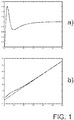
- a power consumption of a device in a certain state basically corresponds to the illustration of Fig. 1a , i.e. to a function of the time since switching to that state. So after a switching time of approximately 30 time units, the power consumption is more or less constant.
- the obtaining unit is arranged for obtaining data sets corresponding to time intervals during which no change of the operation states of the loads occur.
- a vector x with least norm that gives a least squares solution to the above matrix equation is of less interest that least squares solutions of which all components (representing power levels) are non-negative (assuming that only power consuming loads are present). This is a problem of constrained quadratic optimization.
- Fig. 1 shows an illustration of a change in power consumption after switching from one operation state to another operation state and shows an illustration of corresponding energy consumption together with a linear approximation thereof.
- a brief discussion of Fig. 1 is already provided above.
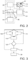
- Fig. 2 shows an illustration of an embodiment of a device 35 for determining an individual power representation of each operation state of each load 15 of a plurality 10 of loads according to the present invention.
- the embodiment is limited to the case of the loads 15 being just consuming loads, i.e. the plurality of loads does not include a generator or the like.
- a plurality 10 of loads 15 (if applicable including sub-loads 20) is provided by electrical energy, wherein the amount of energy consumed is monitored by an energy meter 25. Furthermore, a control unit 30 is provided which exerts control over the operation states of the loads 15 and also provides the functionality of a state monitor in giving information of the operation states of the loads 15.
- the energy meter 25 and the control unit 30 provide their information to a determining device 35, which includes an obtaining unit 40 and a calculating unit 45.
- the determining device 35 is coupled to a malfunction monitor 50.
- the determining device 35 together with the energy meter 25 and the control unit 30 forms a system 55 for determining an individual power representation of each operation state of each load 15 of a plurality 10 of loads, whereas the system 55 and the malfunction monitor 50 are part of an arrangement 60 for monitoring a malfunction in a load 15 in the plurality 10 of loads.
- the control unit 30 controls the operation states of the loads 15 and provides information on such operation states and in particular about changes in the operation states to the determining device 35.
- the energy meter 25 measures the energy consumptions of the plurality 10 of loads during respective time intervals, wherein the total energy consumptions of the plurality 10 of loads are measured without information on separate energy consumptions of individual loads 15 being available.
- the obtaining unit 40 obtains the information from the energy meter 25 and the control unit 30 in form of a plurality of mutually different data sets.
- Each data set corresponds to a time interval and includes the total energy consumption (or more generally energy throughput) of the plurality 10 of loads during said time interval. Further, the data set includes also the information provided by the control unit 30 on all operation states of each load of the plurality of loads during said time interval.
- the number of data sets obtained by the obtaining unit 40 is equal to or larger than the combined number of operation states of the plurality of loads. If more than one parameter is used for the representation of the power of a load 15, the number of data sets is increased accordingly.
- the data sets are provided to the calculating unit 45 which then calculates a set of the individual power representations of the operation states of the plurality 10 of loads, such that the calculated set provides a minimization, for all time intervals, of the differences between the obtained total energy throughput of the respective time interval and a combined energy throughput resulting from the operation states of the plurality 10 of loads during said respective time interval.
- the malfunction monitor 50 is provided with different sets of the individual power representations of the operation states of the plurality 10 of loads and checks for changes between different sets. If there is a change beyond a predetermined threshold in the power consumption or representation of an individual load 15, in particular if the power consumption falls or rises significantly, this might indicate a malfunction of the particular load 15, wherein the malfunction monitor 50 will indicate such possible malfunction candidate.
- Fig. 3 shows flow chart of an embodiment of a method for determining an individual power representation of each operation state of each load of a plurality of loads according to the present invention.
- step 105 operation states of loads of a plurality of loads are changed, if applicable and information of the operation states and their changes is provided.
- step 110 the total energy consumption of the plurality of loads is measured in step 110.
- step 115 The information on the operation states and their changes and the information on the total energy consumption are gathered or obtained in step 115, wherein steps 105, 110 and 115 are repeated until a predetermined number of mutually different data sets including the total energy consumption during the time interval and the corresponding information on the operation states and their changes are obtained (check in step 120).
- a set of the individual power representations of the operation states of the plurality of loads is calculated in step 125, said set providing a minimization, for all time intervals, of the differences between the obtained total energy throughput of the respective time interval and a combined energy throughput resulting from the operation states of the plurality of loads during said respective time interval.
- the process returns to steps 105, 110 and 115, wherein furthermore the set of power representations is checked (step 130) for substantial differences to previously obtained set if power representations in order to monitor for possible malfunctions expressing as changes in power consumption.
- the device for determining an individual power representation of each operation state of each load of a plurality of loads controls the operation states by itself, as not the control as such is important but the information on the operation states.
- a single unit or device may fulfill the functions of several items recited in the claims.
- the mere fact that certain measures are recited in mutually different dependent claims does not indicate that a combination of these measures cannot be used to advantage.
- Operations like measuring, determining and calculating can be implemented as program code means of a computer program and/or as dedicated hardware.
- a computer program may be stored and/or distributed on a suitable medium, such as an optical storage medium or a solid-state medium, supplied together with or as part of other hardware, but may also be distributed in other forms, such as via the Internet or other wired or wireless telecommunication systems.
- a suitable medium such as an optical storage medium or a solid-state medium, supplied together with or as part of other hardware, but may also be distributed in other forms, such as via the Internet or other wired or wireless telecommunication systems.
Landscapes
- Engineering & Computer Science (AREA)
- Business, Economics & Management (AREA)
- Physics & Mathematics (AREA)
- General Physics & Mathematics (AREA)
- Power Engineering (AREA)
- Health & Medical Sciences (AREA)
- Economics (AREA)
- Public Health (AREA)
- Marketing (AREA)
- Primary Health Care (AREA)
- Strategic Management (AREA)
- Tourism & Hospitality (AREA)
- Human Resources & Organizations (AREA)
- General Business, Economics & Management (AREA)
- General Health & Medical Sciences (AREA)
- Theoretical Computer Science (AREA)
- Water Supply & Treatment (AREA)
- Supply And Distribution Of Alternating Current (AREA)
Claims (6)
- Dispositif (35) pour déterminer une représentation de puissance individuelle de chaque état de fonctionnement de chaque charge (15) d'une pluralité (10) de charges, un état de fonctionnement d'une charge (15) étant un état dans lequel ladite charge (15) consomme ou génère de l'énergie, ledit dispositif (35) incluant
une unité d'obtention (40) pour obtenir une pluralité d'ensembles de données mutuellement différents, chaque ensemble de données correspondant à un intervalle de temps, dans lequel chaque ensemble de données inclut une production énergétique totale de la pluralité (10) de charges durant ledit intervalle de temps et des informations sur tous les états de fonctionnement de chaque charge (15) de la pluralité (10) de charges durant ledit intervalle de temps, le nombre d'ensembles de données étant supérieur ou égal au nombre combiné d'états de fonctionnement de la pluralité (10) de charges, et
une unité de calcul (45) pour calculer un ensemble des représentations de puissance individuelles des états de fonctionnement de la pluralité (10) de charges, ledit ensemble fournissant une minimisation, pour tous les intervalles de temps, des différences entre la production énergétique totale obtenue de l'intervalle de temps respectif et une production énergétique combinée résultant des états de fonctionnement de la pluralité (10) de charges durant ledit intervalle de temps respectif,
dans lequel les représentations de puissance sont des représentations de puissance linéaires correspondant à une puissance constante et incluant un décalage énergétique et l'unité de calcul (45) est agencée pour calculer une production énergétique d'un état de fonctionnement sur la base de la période de temps durant laquelle l'état de fonctionnement est actif au cours de l'intervalle de temps respectif, dans lequel ledit décalage énergétique incorpore les effets liés au démarrage ou à l'arrêt d'une charge. - Dispositif (35) selon la revendication 1,
dans lequel l'unité d'obtention (40) est agencée pour obtenir des ensembles de données correspondant à des intervalles de temps durant lesquels aucun changement des états de fonctionnement des charges ne se produit. - Système (55) pour déterminer une représentation de puissance individuelle de chaque état de fonctionnement de chaque charge (15) d'une pluralité (10) de charges, ledit système (55) incluant
le dispositif (35) selon la revendication 1,
un compteur d'énergie (25) pour mesurer une production énergétique totale pour un intervalle de temps donné, et
un appareil de surveillance d'état (30) pour surveiller les états de fonctionnement des charges (15) et pour générer les informations sur tous les états de fonctionnement de chaque charge (15) de la pluralité (10) de charges durant ledit intervalle de temps. - Agencement (60) pour déceler un dysfonctionnement d'une charge (15) dans une pluralité (10) de charges, ledit agencement (60) incluant
le système (55) selon la revendication 3, et
un appareil de surveillance de dysfonctionnement (50) pour détecter un changement des représentations de puissance des états de fonctionnement de la pluralité (10) de charges déterminées par ledit système (55). - Procédé pour déterminer une représentation de puissance individuelle de chaque état de fonctionnement de chaque charge (15) d'une pluralité (10) de charges, un état de fonctionnement d'une charge étant un état dans lequel ladite charge (15) consomme ou génère de l'énergie, ledit procédé incluant les étapes de
obtention (115) d'une pluralité d'ensembles de données mutuellement différents, chaque ensemble de données correspondant à un intervalle de temps, dans lequel chaque ensemble de données inclut une production énergétique totale de la pluralité (10) de charges durant ledit intervalle de temps et des informations sur tous les états de fonctionnement de chaque charge (15) de la pluralité (10) de charges durant ledit intervalle de temps, le nombre d'ensembles de données étant supérieur ou égal au nombre combiné d'états de fonctionnement de la pluralité (10) de charges, et
calcul (125) d'un ensemble des représentations de puissance individuelles des états de fonctionnement de la pluralité (10) de charges, ledit ensemble fournissant une minimisation, pour tous les intervalles de temps, des différences entre la production énergétique totale obtenue de l'intervalle de temps respectif et une production énergétique combinée résultant des états de fonctionnement de la pluralité (10) de charges durant ledit intervalle de temps respectif,
dans lequel les représentations de puissance sont des représentations de puissance linéaires correspondant à une puissance constante et incluant un décalage énergétique et l'étape de calcul inclut le calcul d'une production énergétique d'un état de fonctionnement sur la base de la période de temps durant laquelle l'état de fonctionnement est actif au cours de l'intervalle de temps respectif, dans lequel ledit décalage énergétique incorpore les effets liés au démarrage ou à l'arrêt d'une charge. - Programme informatique pour déterminer une représentation de puissance individuelle de chaque état de fonctionnement de chaque charge (15) d'une pluralité de charges (10), le programme informatique comprenant un moyen de code de programme pour amener le dispositif (35) selon la revendication 1 à réaliser les étapes du procédé selon la revendication 5 lorsque le programme informatique est exécuté sur ledit dispositif (35).
Applications Claiming Priority (2)
| Application Number | Priority Date | Filing Date | Title |
|---|---|---|---|
| US201261717234P | 2012-10-23 | 2012-10-23 | |
| PCT/IB2013/059293 WO2014064570A1 (fr) | 2012-10-23 | 2013-10-11 | Dispositif et procédé pour déterminer une représentation de puissance individuelle d'états de fonctionnement |
Publications (2)
| Publication Number | Publication Date |
|---|---|
| EP2912477A1 EP2912477A1 (fr) | 2015-09-02 |
| EP2912477B1 true EP2912477B1 (fr) | 2018-08-29 |
Family
ID=49918746
Family Applications (1)
| Application Number | Title | Priority Date | Filing Date |
|---|---|---|---|
| EP13817978.3A Revoked EP2912477B1 (fr) | 2012-10-23 | 2013-10-11 | Dispositif et procédé pour déterminer une représentation de puissance individuelle d'états de fonctionnement |
Country Status (3)
| Country | Link |
|---|---|
| US (1) | US20150276828A1 (fr) |
| EP (1) | EP2912477B1 (fr) |
| WO (1) | WO2014064570A1 (fr) |
Families Citing this family (4)
| Publication number | Priority date | Publication date | Assignee | Title |
|---|---|---|---|---|
| CA2871616C (fr) | 2012-04-25 | 2019-10-08 | Bidgely Inc. | Techniques de desagregation d'energie destinees a des donnees a basse resolution sur la consommation d'energie domestique |
| CA2960001C (fr) | 2014-09-04 | 2022-07-12 | Bidgely Inc. | Systemes et procedes d'optimisation d'utilisation d'energie au moyen de donnees de desagregation d'energie et d'informations de temps d'utilisation |
| US9477243B2 (en) * | 2014-12-22 | 2016-10-25 | Intel Corporation | System maximum current protection |
| US20170330103A1 (en) * | 2016-05-13 | 2017-11-16 | Alex Shyr | Systems and Methods for Learning Appliance Signatures |
Citations (8)
| Publication number | Priority date | Publication date | Assignee | Title |
|---|---|---|---|---|
| US20070203658A1 (en) | 2004-10-01 | 2007-08-30 | Patel Sureshchandra B | System And Method Of Parallel Loadflow Computation For Electrical Power System |
| EP2026299A1 (fr) | 2007-08-14 | 2009-02-18 | General Electric Company | Mètre électrique cognitif |
| US7580775B2 (en) | 2006-07-11 | 2009-08-25 | Regen Energy Inc. | Method and apparatus for implementing enablement state decision for energy consuming load based on demand and duty cycle of load |
| US20110112780A1 (en) | 2009-11-06 | 2011-05-12 | David Moss | Electrical power consumption measuring system |
| US20110144819A1 (en) | 2009-12-16 | 2011-06-16 | Robert Bosch Gmbh | Method for non-intrusive load monitoring using a hybrid systems state estimation approach |
| WO2011130670A2 (fr) | 2010-04-15 | 2011-10-20 | Yale University | Contrôle de coupure de consommation par détection d'état de puissance |
| US20110302125A1 (en) | 2010-06-08 | 2011-12-08 | Honeywell International Inc. | Systems and methods for virtual sub-metering |
| WO2012106709A2 (fr) | 2011-02-04 | 2012-08-09 | Myenersave, Inc. | Systèmes et procédés d'amélioration de la précision de désagrégation de niveau appareil dans techniques de surveillance de charge d'appareil non intrusives |
Family Cites Families (5)
| Publication number | Priority date | Publication date | Assignee | Title |
|---|---|---|---|---|
| US7069161B2 (en) * | 2002-01-17 | 2006-06-27 | Gristina Family Trust | System for managing resource infrastructure and resource consumption in real time |
| US7529947B2 (en) * | 2004-03-31 | 2009-05-05 | Marvell International Ltd. | Determining power consumption of an application |
| US7174260B2 (en) * | 2004-04-01 | 2007-02-06 | Blue Line Innovations Inc. | System and method for reading power meters |
| WO2010096783A1 (fr) * | 2009-02-20 | 2010-08-26 | The Trustees Of Columbia University In The City Of New York | Système de prévention et d'atténuation de contingence dynamique |
| US20100305889A1 (en) * | 2009-05-27 | 2010-12-02 | General Electric Company | Non-intrusive appliance load identification using cascaded cognitive learning |
-
2013
- 2013-10-11 EP EP13817978.3A patent/EP2912477B1/fr not_active Revoked
- 2013-10-11 WO PCT/IB2013/059293 patent/WO2014064570A1/fr not_active Ceased
- 2013-10-11 US US14/434,923 patent/US20150276828A1/en not_active Abandoned
Patent Citations (8)
| Publication number | Priority date | Publication date | Assignee | Title |
|---|---|---|---|---|
| US20070203658A1 (en) | 2004-10-01 | 2007-08-30 | Patel Sureshchandra B | System And Method Of Parallel Loadflow Computation For Electrical Power System |
| US7580775B2 (en) | 2006-07-11 | 2009-08-25 | Regen Energy Inc. | Method and apparatus for implementing enablement state decision for energy consuming load based on demand and duty cycle of load |
| EP2026299A1 (fr) | 2007-08-14 | 2009-02-18 | General Electric Company | Mètre électrique cognitif |
| US20110112780A1 (en) | 2009-11-06 | 2011-05-12 | David Moss | Electrical power consumption measuring system |
| US20110144819A1 (en) | 2009-12-16 | 2011-06-16 | Robert Bosch Gmbh | Method for non-intrusive load monitoring using a hybrid systems state estimation approach |
| WO2011130670A2 (fr) | 2010-04-15 | 2011-10-20 | Yale University | Contrôle de coupure de consommation par détection d'état de puissance |
| US20110302125A1 (en) | 2010-06-08 | 2011-12-08 | Honeywell International Inc. | Systems and methods for virtual sub-metering |
| WO2012106709A2 (fr) | 2011-02-04 | 2012-08-09 | Myenersave, Inc. | Systèmes et procédés d'amélioration de la précision de désagrégation de niveau appareil dans techniques de surveillance de charge d'appareil non intrusives |
Non-Patent Citations (1)
| Title |
|---|
| MARIO E. BERGES ET AL.: "Enhancing Electricity Audits in Residential Buildings with Nonintrusive Load Monitoring", JOURNAL OF INDUSTRIAL ECOLOGY, vol. 14, no. 5, 29 October 2010 (2010-10-29), pages 844 - 858, XP055603704 |
Also Published As
| Publication number | Publication date |
|---|---|
| WO2014064570A1 (fr) | 2014-05-01 |
| EP2912477A1 (fr) | 2015-09-02 |
| US20150276828A1 (en) | 2015-10-01 |
Similar Documents
| Publication | Publication Date | Title |
|---|---|---|
| US9964932B2 (en) | Virtual demand auditing of devices in a building | |
| US10554077B2 (en) | Automated monitoring for changes in energy consumption patterns | |
| US7937247B2 (en) | Virtual metering | |
| CA2711994C (fr) | Systeme et methode de decouverte de modeles electriques | |
| US8532808B2 (en) | Systems and methods for measuring and verifying energy savings in buildings | |
| RU2428708C2 (ru) | Способ и система для поверки измерительных приборов | |
| US10417565B1 (en) | System, method, and computer program for modeling and predicting energy consumption in a building | |
| CN105485831A (zh) | 管理加热、通风和空气调节的方法和设备 | |
| JP3199536B2 (ja) | ガス器具別使用量解析装置 | |
| EP2912477B1 (fr) | Dispositif et procédé pour déterminer une représentation de puissance individuelle d'états de fonctionnement | |
| KR20140116619A (ko) | 에너지 사용량 예측 시스템 및 방법 | |
| US20130151212A1 (en) | Systems, methods and devices for determining energy conservation measure savings | |
| KR102041417B1 (ko) | 기온 분포를 사용한 측정 및 검증 가중 방법 및 시스템 | |
| KR20160077740A (ko) | 건물 에너지 사용량 예측시스템과 예측방법 | |
| CN112581012B (zh) | 参与需求响应的用电客户分类方法 | |
| AU2017231042A1 (en) | Disaggregation of appliance usage from electrical meter data | |
| KR102036166B1 (ko) | 미검침 구간의 검침 데이터 예측 및 보정 방법과 그 장치 | |
| KR20140122010A (ko) | 태양광 모듈의 전력 데이터 관리 향상을 위한 검침 데이터 보정 방법 및 장치 | |
| CN119828032B (zh) | 一种蓄电池的健康状态检测方法及装置 | |
| KR102591223B1 (ko) | 난방도일과 냉방도일을 적용한 시계열 분석을 사용한 ami 고객기준부하 산정 방법 | |
| Woodall | SMART 2011/0072: methodology for energy efficiency mea-surements applicable to ICT in buildings (eeMeasure) | |
| Benedá et al. | An Proposal to Energy Consumption Estimation of Residential Loads based on State Sensors Devices | |
| Mwansa et al. | Towards Smart Meter Energy Analysis and Profiling to Support Low Carbon Emissions | |
| Bergés et al. | Evaluating the electric consumption of residential buildings: Current practices and future prospects | |
| KR102371460B1 (ko) | 냉난방기기 에너지 사용량 및 절감량 추정 시스템과 그 방법 |
Legal Events
| Date | Code | Title | Description |
|---|---|---|---|
| PUAI | Public reference made under article 153(3) epc to a published international application that has entered the european phase |
Free format text: ORIGINAL CODE: 0009012 |
|
| 17P | Request for examination filed |
Effective date: 20150526 |
|
| AK | Designated contracting states |
Kind code of ref document: A1 Designated state(s): AL AT BE BG CH CY CZ DE DK EE ES FI FR GB GR HR HU IE IS IT LI LT LU LV MC MK MT NL NO PL PT RO RS SE SI SK SM TR |
|
| AX | Request for extension of the european patent |
Extension state: BA ME |
|
| DAX | Request for extension of the european patent (deleted) | ||
| RAP1 | Party data changed (applicant data changed or rights of an application transferred) |
Owner name: PHILIPS LIGHTING HOLDING B.V. |
|
| RIN1 | Information on inventor provided before grant (corrected) |
Inventor name: FILIPPI, ALESSIO Inventor name: RIETMAN, RONALD Inventor name: WANG, YING |
|
| GRAP | Despatch of communication of intention to grant a patent |
Free format text: ORIGINAL CODE: EPIDOSNIGR1 |
|
| STAA | Information on the status of an ep patent application or granted ep patent |
Free format text: STATUS: GRANT OF PATENT IS INTENDED |
|
| RIC1 | Information provided on ipc code assigned before grant |
Ipc: G01D 4/00 20060101ALI20180306BHEP Ipc: G06Q 50/06 20120101ALI20180306BHEP Ipc: G01R 21/00 20060101ALI20180306BHEP Ipc: G01R 21/133 20060101AFI20180306BHEP |
|
| INTG | Intention to grant announced |
Effective date: 20180321 |
|
| GRAS | Grant fee paid |
Free format text: ORIGINAL CODE: EPIDOSNIGR3 |
|
| GRAA | (expected) grant |
Free format text: ORIGINAL CODE: 0009210 |
|
| STAA | Information on the status of an ep patent application or granted ep patent |
Free format text: STATUS: THE PATENT HAS BEEN GRANTED |
|
| AK | Designated contracting states |
Kind code of ref document: B1 Designated state(s): AL AT BE BG CH CY CZ DE DK EE ES FI FR GB GR HR HU IE IS IT LI LT LU LV MC MK MT NL NO PL PT RO RS SE SI SK SM TR |
|
| REG | Reference to a national code |
Ref country code: GB Ref legal event code: FG4D |
|
| REG | Reference to a national code |
Ref country code: CH Ref legal event code: EP |
|
| REG | Reference to a national code |
Ref country code: AT Ref legal event code: REF Ref document number: 1035748 Country of ref document: AT Kind code of ref document: T Effective date: 20180915 |
|
| REG | Reference to a national code |
Ref country code: IE Ref legal event code: FG4D |
|
| REG | Reference to a national code |
Ref country code: DE Ref legal event code: R096 Ref document number: 602013042871 Country of ref document: DE |
|
| REG | Reference to a national code |
Ref country code: FR Ref legal event code: PLFP Year of fee payment: 6 |
|
| RAP2 | Party data changed (patent owner data changed or rights of a patent transferred) |
Owner name: PHILIPS LIGHTING HOLDING B.V. |
|
| REG | Reference to a national code |
Ref country code: NL Ref legal event code: MP Effective date: 20180829 |
|
| REG | Reference to a national code |
Ref country code: LT Ref legal event code: MG4D |
|
| PG25 | Lapsed in a contracting state [announced via postgrant information from national office to epo] |
Ref country code: SE Free format text: LAPSE BECAUSE OF FAILURE TO SUBMIT A TRANSLATION OF THE DESCRIPTION OR TO PAY THE FEE WITHIN THE PRESCRIBED TIME-LIMIT Effective date: 20180829 Ref country code: NL Free format text: LAPSE BECAUSE OF FAILURE TO SUBMIT A TRANSLATION OF THE DESCRIPTION OR TO PAY THE FEE WITHIN THE PRESCRIBED TIME-LIMIT Effective date: 20180829 Ref country code: BG Free format text: LAPSE BECAUSE OF FAILURE TO SUBMIT A TRANSLATION OF THE DESCRIPTION OR TO PAY THE FEE WITHIN THE PRESCRIBED TIME-LIMIT Effective date: 20181129 Ref country code: FI Free format text: LAPSE BECAUSE OF FAILURE TO SUBMIT A TRANSLATION OF THE DESCRIPTION OR TO PAY THE FEE WITHIN THE PRESCRIBED TIME-LIMIT Effective date: 20180829 Ref country code: IS Free format text: LAPSE BECAUSE OF FAILURE TO SUBMIT A TRANSLATION OF THE DESCRIPTION OR TO PAY THE FEE WITHIN THE PRESCRIBED TIME-LIMIT Effective date: 20181229 Ref country code: NO Free format text: LAPSE BECAUSE OF FAILURE TO SUBMIT A TRANSLATION OF THE DESCRIPTION OR TO PAY THE FEE WITHIN THE PRESCRIBED TIME-LIMIT Effective date: 20181129 Ref country code: RS Free format text: LAPSE BECAUSE OF FAILURE TO SUBMIT A TRANSLATION OF THE DESCRIPTION OR TO PAY THE FEE WITHIN THE PRESCRIBED TIME-LIMIT Effective date: 20180829 Ref country code: GR Free format text: LAPSE BECAUSE OF FAILURE TO SUBMIT A TRANSLATION OF THE DESCRIPTION OR TO PAY THE FEE WITHIN THE PRESCRIBED TIME-LIMIT Effective date: 20181130 Ref country code: LT Free format text: LAPSE BECAUSE OF FAILURE TO SUBMIT A TRANSLATION OF THE DESCRIPTION OR TO PAY THE FEE WITHIN THE PRESCRIBED TIME-LIMIT Effective date: 20180829 |
|
| REG | Reference to a national code |
Ref country code: AT Ref legal event code: MK05 Ref document number: 1035748 Country of ref document: AT Kind code of ref document: T Effective date: 20180829 |
|
| PG25 | Lapsed in a contracting state [announced via postgrant information from national office to epo] |
Ref country code: LV Free format text: LAPSE BECAUSE OF FAILURE TO SUBMIT A TRANSLATION OF THE DESCRIPTION OR TO PAY THE FEE WITHIN THE PRESCRIBED TIME-LIMIT Effective date: 20180829 Ref country code: HR Free format text: LAPSE BECAUSE OF FAILURE TO SUBMIT A TRANSLATION OF THE DESCRIPTION OR TO PAY THE FEE WITHIN THE PRESCRIBED TIME-LIMIT Effective date: 20180829 Ref country code: AL Free format text: LAPSE BECAUSE OF FAILURE TO SUBMIT A TRANSLATION OF THE DESCRIPTION OR TO PAY THE FEE WITHIN THE PRESCRIBED TIME-LIMIT Effective date: 20180829 |
|
| PGFP | Annual fee paid to national office [announced via postgrant information from national office to epo] |
Ref country code: FR Payment date: 20181025 Year of fee payment: 6 Ref country code: GB Payment date: 20181031 Year of fee payment: 6 |
|
| RAP2 | Party data changed (patent owner data changed or rights of a patent transferred) |
Owner name: SIGNIFY HOLDING B.V. |
|
| PG25 | Lapsed in a contracting state [announced via postgrant information from national office to epo] |
Ref country code: CZ Free format text: LAPSE BECAUSE OF FAILURE TO SUBMIT A TRANSLATION OF THE DESCRIPTION OR TO PAY THE FEE WITHIN THE PRESCRIBED TIME-LIMIT Effective date: 20180829 Ref country code: RO Free format text: LAPSE BECAUSE OF FAILURE TO SUBMIT A TRANSLATION OF THE DESCRIPTION OR TO PAY THE FEE WITHIN THE PRESCRIBED TIME-LIMIT Effective date: 20180829 Ref country code: PL Free format text: LAPSE BECAUSE OF FAILURE TO SUBMIT A TRANSLATION OF THE DESCRIPTION OR TO PAY THE FEE WITHIN THE PRESCRIBED TIME-LIMIT Effective date: 20180829 Ref country code: ES Free format text: LAPSE BECAUSE OF FAILURE TO SUBMIT A TRANSLATION OF THE DESCRIPTION OR TO PAY THE FEE WITHIN THE PRESCRIBED TIME-LIMIT Effective date: 20180829 Ref country code: EE Free format text: LAPSE BECAUSE OF FAILURE TO SUBMIT A TRANSLATION OF THE DESCRIPTION OR TO PAY THE FEE WITHIN THE PRESCRIBED TIME-LIMIT Effective date: 20180829 Ref country code: AT Free format text: LAPSE BECAUSE OF FAILURE TO SUBMIT A TRANSLATION OF THE DESCRIPTION OR TO PAY THE FEE WITHIN THE PRESCRIBED TIME-LIMIT Effective date: 20180829 Ref country code: IT Free format text: LAPSE BECAUSE OF FAILURE TO SUBMIT A TRANSLATION OF THE DESCRIPTION OR TO PAY THE FEE WITHIN THE PRESCRIBED TIME-LIMIT Effective date: 20180829 |
|
| PGFP | Annual fee paid to national office [announced via postgrant information from national office to epo] |
Ref country code: DE Payment date: 20181228 Year of fee payment: 6 |
|
| REG | Reference to a national code |
Ref country code: DE Ref legal event code: R026 Ref document number: 602013042871 Country of ref document: DE |
|
| PG25 | Lapsed in a contracting state [announced via postgrant information from national office to epo] |
Ref country code: SK Free format text: LAPSE BECAUSE OF FAILURE TO SUBMIT A TRANSLATION OF THE DESCRIPTION OR TO PAY THE FEE WITHIN THE PRESCRIBED TIME-LIMIT Effective date: 20180829 Ref country code: SM Free format text: LAPSE BECAUSE OF FAILURE TO SUBMIT A TRANSLATION OF THE DESCRIPTION OR TO PAY THE FEE WITHIN THE PRESCRIBED TIME-LIMIT Effective date: 20180829 Ref country code: DK Free format text: LAPSE BECAUSE OF FAILURE TO SUBMIT A TRANSLATION OF THE DESCRIPTION OR TO PAY THE FEE WITHIN THE PRESCRIBED TIME-LIMIT Effective date: 20180829 |
|
| REG | Reference to a national code |
Ref country code: CH Ref legal event code: PL |
|
| PLBI | Opposition filed |
Free format text: ORIGINAL CODE: 0009260 |
|
| PLAX | Notice of opposition and request to file observation + time limit sent |
Free format text: ORIGINAL CODE: EPIDOSNOBS2 |
|
| REG | Reference to a national code |
Ref country code: BE Ref legal event code: MM Effective date: 20181031 |
|
| PG25 | Lapsed in a contracting state [announced via postgrant information from national office to epo] |
Ref country code: MC Free format text: LAPSE BECAUSE OF FAILURE TO SUBMIT A TRANSLATION OF THE DESCRIPTION OR TO PAY THE FEE WITHIN THE PRESCRIBED TIME-LIMIT Effective date: 20180829 Ref country code: LU Free format text: LAPSE BECAUSE OF NON-PAYMENT OF DUE FEES Effective date: 20181011 |
|
| 26 | Opposition filed |
Opponent name: MOLNIA, DAVID Effective date: 20190529 |
|
| REG | Reference to a national code |
Ref country code: IE Ref legal event code: MM4A |
|
| PG25 | Lapsed in a contracting state [announced via postgrant information from national office to epo] |
Ref country code: CH Free format text: LAPSE BECAUSE OF NON-PAYMENT OF DUE FEES Effective date: 20181031 Ref country code: LI Free format text: LAPSE BECAUSE OF NON-PAYMENT OF DUE FEES Effective date: 20181031 Ref country code: SI Free format text: LAPSE BECAUSE OF FAILURE TO SUBMIT A TRANSLATION OF THE DESCRIPTION OR TO PAY THE FEE WITHIN THE PRESCRIBED TIME-LIMIT Effective date: 20180829 Ref country code: BE Free format text: LAPSE BECAUSE OF NON-PAYMENT OF DUE FEES Effective date: 20181031 |
|
| PG25 | Lapsed in a contracting state [announced via postgrant information from national office to epo] |
Ref country code: IE Free format text: LAPSE BECAUSE OF NON-PAYMENT OF DUE FEES Effective date: 20181011 |
|
| PLBB | Reply of patent proprietor to notice(s) of opposition received |
Free format text: ORIGINAL CODE: EPIDOSNOBS3 |
|
| PG25 | Lapsed in a contracting state [announced via postgrant information from national office to epo] |
Ref country code: MT Free format text: LAPSE BECAUSE OF NON-PAYMENT OF DUE FEES Effective date: 20181011 |
|
| PG25 | Lapsed in a contracting state [announced via postgrant information from national office to epo] |
Ref country code: TR Free format text: LAPSE BECAUSE OF FAILURE TO SUBMIT A TRANSLATION OF THE DESCRIPTION OR TO PAY THE FEE WITHIN THE PRESCRIBED TIME-LIMIT Effective date: 20180829 |
|
| REG | Reference to a national code |
Ref country code: DE Ref legal event code: R119 Ref document number: 602013042871 Country of ref document: DE |
|
| PG25 | Lapsed in a contracting state [announced via postgrant information from national office to epo] |
Ref country code: PT Free format text: LAPSE BECAUSE OF FAILURE TO SUBMIT A TRANSLATION OF THE DESCRIPTION OR TO PAY THE FEE WITHIN THE PRESCRIBED TIME-LIMIT Effective date: 20180829 |
|
| PG25 | Lapsed in a contracting state [announced via postgrant information from national office to epo] |
Ref country code: HU Free format text: LAPSE BECAUSE OF FAILURE TO SUBMIT A TRANSLATION OF THE DESCRIPTION OR TO PAY THE FEE WITHIN THE PRESCRIBED TIME-LIMIT; INVALID AB INITIO Effective date: 20131011 Ref country code: CY Free format text: LAPSE BECAUSE OF FAILURE TO SUBMIT A TRANSLATION OF THE DESCRIPTION OR TO PAY THE FEE WITHIN THE PRESCRIBED TIME-LIMIT Effective date: 20180829 Ref country code: MK Free format text: LAPSE BECAUSE OF NON-PAYMENT OF DUE FEES Effective date: 20180829 |
|
| REG | Reference to a national code |
Ref country code: DE Ref legal event code: R064 Ref document number: 602013042871 Country of ref document: DE Ref country code: DE Ref legal event code: R103 Ref document number: 602013042871 Country of ref document: DE |
|
| RDAF | Communication despatched that patent is revoked |
Free format text: ORIGINAL CODE: EPIDOSNREV1 |
|
| PG25 | Lapsed in a contracting state [announced via postgrant information from national office to epo] |
Ref country code: DE Free format text: LAPSE BECAUSE OF NON-PAYMENT OF DUE FEES Effective date: 20200501 |
|
| GBPC | Gb: european patent ceased through non-payment of renewal fee |
Effective date: 20191011 |
|
| RDAG | Patent revoked |
Free format text: ORIGINAL CODE: 0009271 |
|
| STAA | Information on the status of an ep patent application or granted ep patent |
Free format text: STATUS: PATENT REVOKED |
|
| PG25 | Lapsed in a contracting state [announced via postgrant information from national office to epo] |
Ref country code: GB Free format text: LAPSE BECAUSE OF NON-PAYMENT OF DUE FEES Effective date: 20191011 Ref country code: FR Free format text: LAPSE BECAUSE OF NON-PAYMENT OF DUE FEES Effective date: 20191031 |
|
| 27W | Patent revoked |
Effective date: 20200702 |
|
| REG | Reference to a national code |
Ref country code: FI Ref legal event code: MGE |