EP2912858B1 - Mikrogefertigte ultraschallwandlerarrays mit mehreren harmonischen modi - Google Patents
Mikrogefertigte ultraschallwandlerarrays mit mehreren harmonischen modi Download PDFInfo
- Publication number
- EP2912858B1 EP2912858B1 EP13848357.3A EP13848357A EP2912858B1 EP 2912858 B1 EP2912858 B1 EP 2912858B1 EP 13848357 A EP13848357 A EP 13848357A EP 2912858 B1 EP2912858 B1 EP 2912858B1
- Authority
- EP
- European Patent Office
- Prior art keywords
- oscillation
- modes
- membrane
- frequency band
- array
- Prior art date
- Legal status (The legal status is an assumption and is not a legal conclusion. Google has not performed a legal analysis and makes no representation as to the accuracy of the status listed.)
- Active
Links
Images





Classifications
-
- B—PERFORMING OPERATIONS; TRANSPORTING
- B06—GENERATING OR TRANSMITTING MECHANICAL VIBRATIONS IN GENERAL
- B06B—METHODS OR APPARATUS FOR GENERATING OR TRANSMITTING MECHANICAL VIBRATIONS OF INFRASONIC, SONIC, OR ULTRASONIC FREQUENCY, e.g. FOR PERFORMING MECHANICAL WORK IN GENERAL
- B06B1/00—Methods or apparatus for generating mechanical vibrations of infrasonic, sonic, or ultrasonic frequency
- B06B1/02—Methods or apparatus for generating mechanical vibrations of infrasonic, sonic, or ultrasonic frequency making use of electrical energy
- B06B1/0207—Driving circuits
- B06B1/0223—Driving circuits for generating signals continuous in time
- B06B1/0269—Driving circuits for generating signals continuous in time for generating multiple frequencies
-
- A—HUMAN NECESSITIES
- A61—MEDICAL OR VETERINARY SCIENCE; HYGIENE
- A61B—DIAGNOSIS; SURGERY; IDENTIFICATION
- A61B18/00—Surgical instruments, devices or methods for transferring non-mechanical forms of energy to or from the body
- A61B18/04—Surgical instruments, devices or methods for transferring non-mechanical forms of energy to or from the body by heating
- A61B18/08—Surgical instruments, devices or methods for transferring non-mechanical forms of energy to or from the body by heating by means of electrically-heated probes
- A61B18/082—Probes or electrodes therefor
-
- B—PERFORMING OPERATIONS; TRANSPORTING
- B06—GENERATING OR TRANSMITTING MECHANICAL VIBRATIONS IN GENERAL
- B06B—METHODS OR APPARATUS FOR GENERATING OR TRANSMITTING MECHANICAL VIBRATIONS OF INFRASONIC, SONIC, OR ULTRASONIC FREQUENCY, e.g. FOR PERFORMING MECHANICAL WORK IN GENERAL
- B06B1/00—Methods or apparatus for generating mechanical vibrations of infrasonic, sonic, or ultrasonic frequency
- B06B1/02—Methods or apparatus for generating mechanical vibrations of infrasonic, sonic, or ultrasonic frequency making use of electrical energy
- B06B1/0207—Driving circuits
- B06B1/0223—Driving circuits for generating signals continuous in time
- B06B1/0269—Driving circuits for generating signals continuous in time for generating multiple frequencies
- B06B1/0276—Driving circuits for generating signals continuous in time for generating multiple frequencies with simultaneous generation, e.g. with modulation, harmonics
-
- B—PERFORMING OPERATIONS; TRANSPORTING
- B06—GENERATING OR TRANSMITTING MECHANICAL VIBRATIONS IN GENERAL
- B06B—METHODS OR APPARATUS FOR GENERATING OR TRANSMITTING MECHANICAL VIBRATIONS OF INFRASONIC, SONIC, OR ULTRASONIC FREQUENCY, e.g. FOR PERFORMING MECHANICAL WORK IN GENERAL
- B06B1/00—Methods or apparatus for generating mechanical vibrations of infrasonic, sonic, or ultrasonic frequency
- B06B1/02—Methods or apparatus for generating mechanical vibrations of infrasonic, sonic, or ultrasonic frequency making use of electrical energy
- B06B1/06—Methods or apparatus for generating mechanical vibrations of infrasonic, sonic, or ultrasonic frequency making use of electrical energy operating with piezoelectric effect or with electrostriction
- B06B1/0607—Methods or apparatus for generating mechanical vibrations of infrasonic, sonic, or ultrasonic frequency making use of electrical energy operating with piezoelectric effect or with electrostriction using multiple elements
- B06B1/0622—Methods or apparatus for generating mechanical vibrations of infrasonic, sonic, or ultrasonic frequency making use of electrical energy operating with piezoelectric effect or with electrostriction using multiple elements on one surface
-
- B—PERFORMING OPERATIONS; TRANSPORTING
- B06—GENERATING OR TRANSMITTING MECHANICAL VIBRATIONS IN GENERAL
- B06B—METHODS OR APPARATUS FOR GENERATING OR TRANSMITTING MECHANICAL VIBRATIONS OF INFRASONIC, SONIC, OR ULTRASONIC FREQUENCY, e.g. FOR PERFORMING MECHANICAL WORK IN GENERAL
- B06B1/00—Methods or apparatus for generating mechanical vibrations of infrasonic, sonic, or ultrasonic frequency
- B06B1/02—Methods or apparatus for generating mechanical vibrations of infrasonic, sonic, or ultrasonic frequency making use of electrical energy
- B06B1/06—Methods or apparatus for generating mechanical vibrations of infrasonic, sonic, or ultrasonic frequency making use of electrical energy operating with piezoelectric effect or with electrostriction
- B06B1/0607—Methods or apparatus for generating mechanical vibrations of infrasonic, sonic, or ultrasonic frequency making use of electrical energy operating with piezoelectric effect or with electrostriction using multiple elements
- B06B1/0622—Methods or apparatus for generating mechanical vibrations of infrasonic, sonic, or ultrasonic frequency making use of electrical energy operating with piezoelectric effect or with electrostriction using multiple elements on one surface
- B06B1/0629—Square array
-
- H—ELECTRICITY
- H10—SEMICONDUCTOR DEVICES; ELECTRIC SOLID-STATE DEVICES NOT OTHERWISE PROVIDED FOR
- H10N—ELECTRIC SOLID-STATE DEVICES NOT OTHERWISE PROVIDED FOR
- H10N30/00—Piezoelectric or electrostrictive devices
- H10N30/01—Manufacture or treatment
- H10N30/08—Shaping or machining of piezoelectric or electrostrictive bodies
- H10N30/081—Shaping or machining of piezoelectric or electrostrictive bodies by coating or depositing using masks, e.g. lift-off
-
- H—ELECTRICITY
- H10—SEMICONDUCTOR DEVICES; ELECTRIC SOLID-STATE DEVICES NOT OTHERWISE PROVIDED FOR
- H10N—ELECTRIC SOLID-STATE DEVICES NOT OTHERWISE PROVIDED FOR
- H10N30/00—Piezoelectric or electrostrictive devices
- H10N30/101—Piezoelectric or electrostrictive devices with electrical and mechanical input and output, e.g. having combined actuator and sensor parts
-
- H—ELECTRICITY
- H10—SEMICONDUCTOR DEVICES; ELECTRIC SOLID-STATE DEVICES NOT OTHERWISE PROVIDED FOR
- H10N—ELECTRIC SOLID-STATE DEVICES NOT OTHERWISE PROVIDED FOR
- H10N30/00—Piezoelectric or electrostrictive devices
- H10N30/80—Constructional details
- H10N30/802—Circuitry or processes for operating piezoelectric or electrostrictive devices not otherwise provided for, e.g. drive circuits
Definitions
- Embodiments of the invention generally relate to ultrasonic transducers, and more specifically pertain to micromachined ultrasonic transducer (MUT) arrays.
- MUT micromachined ultrasonic transducer
- An ultrasonic transducer device typically includes a membrane capable of vibrating in response to a time-varying driving voltage to generate a high frequency pressure wave in a propagation medium (e.g., air, water, or body tissue) in contact with an exposed outer surface of the transducer element.
- a propagation medium e.g., air, water, or body tissue
- This high frequency pressure wave can propagate into other media.
- the same membrane can also receive reflected pressure waves from the propagation media and convert the received pressure waves into electrical signals.
- the electrical signals can be processed in conjunction with the driving voltage signals to obtain information on variations of density or elastic modulus in the propagation media.
- Piezoelectric and capacitive transducer devices have proven useful in the imaging field. While many ultrasonic transducer devices that use piezoelectric membranes are formed by mechanically dicing a bulk piezoelectric material or by injection molding a carrier material infused with piezoelectric ceramic crystals, devices can be advantageously fabricated inexpensively to exceedingly high dimensional tolerances using various micromachining techniques (e.g., material deposition, lithographic patterning, feature formation by etching, etc.). As such, large arrays of transducer elements may be employed with individual ones of the arrays driven via beam forming algorithms. Such arrayed devices are known as piezoelectric MUT (pMUT) arrays. Capacitive transducers may also be similarly micromachined as capacitive MUT (cMUT) arrays.
- pMUT piezoelectric MUT
- cMUT capacitive MUT
- Patent application US2009/301200 discloses an ultrasonic transducer including a substrate having a first electrode therein or on a surface thereof and a diaphragm having a second electrode therein or on a surface thereof, with a cavity therebetween. Further, at least one beam is provided on a surface or inside of the diaphragm or the second electrode.
- Patent application US2007/164631 discloses a capacitive micromachined ultrasonic transducer having an ultrasonic wave transmission/reception surface formed by arranging a plurality of transducer cells each of which includes a membrane having a first electrode and a supporting film for supporting the first electrode, and also includes a second electrode arranged being opposite to the first electrode and being spaced apart from the first electrode at a prescribed interval, wherein: the transducer cells are arranged on the basis of resonant frequencies of the transducer cells.
- Patent US6262946 discloses a capacitive micromachined ultrasonic transducer array which is configured to minimize the excitation and propagation of plate waves traveling in the substrate and ultrasonic waves propagating at the interface between the array surface and the immersion fluid.
- Patent application US2008/013405 discloses a multiple resonances type ultrasonic transducer for a ranging measurement with high directionality using a parametric transmitting array in air, includes an ultrasonic actuator unit formed with a regularly mixing array of first unit actuators having a resonance frequency of f1 and second unit actuators having a resonance frequency of f2.
- Patent application WO 2013/165705 discloses wide bandwidth pMUTs, pMUT arrays and systems having wide bandwidth pMUT arrays.
- a pMUT includes a piezoelectric membrane disposed on a substrate.
- a reference electrode is coupled to the membrane.
- First and second drive/sense electrodes are coupled to the membrane to drive or sense a first and second mode of vibration in the membrane.
- Patent application WO2013165709 discloses pMUT arrays and systems comprising pMUT arrays.
- Coupling strength within a population of transducer elements provides degenerate mode shapes that split for wide bandwidth total response while less coupling strength between adjacent element populations provides adequately low crosstalk between the element populations.
- differing membrane sizes within a population of transducer elements provides differing frequency response for wide bandwidth total response while layout of the differing membrane sizes between adjacent element populations provides adequately low crosstalk between the element populations.
- elliptical piezoelectric membranes provide multiple resonant modes for wide bandwidth total response and high efficiency.
- the invention proposes an apparatus for generating and sensing pressure waves in a medium as claimed in claim 1.
- the invention also proposes a method of generating and sensing pressure waves in a medium as claimed in claim 11.
- a transducer element population of a MUT array is configured for multiple modes of oscillation. These multiple modes include at least a first and second resonant mode, and may further include third, forth, and higher modes. Such multi-resonant mode, or multi-harmonic mode, MUT arrays are referred to herein simply as "multi-mode" MUT arrays.
- harmonics are made in-phase through dimensioning of membrane sizes and arranging the membranes of differing size to mitigate or avoid destructive interaction between proximate membranes within a channel, or crosstalk between proximate channels.
- a multi-mode MUT array is operated with the entire bandwidth associated with the multiple resonant modes employed in both sending and receiving modes of an ultrasonic transducer to achieve a super-wide bandwidth.
- membranes are sized and driven with an electrical signal to induce a first order mode of vibration that has a frequency band that overlaps with that associated predominantly with the second order mode of vibration.
- a multi-mode MUT array is operated with bandwidth associated with the multiple resonant modes apportioned between sending and receiving modes of an ultrasonic transducer.
- a first order mode of vibration suitable as a transmission band is induced by a drive signal and a frequencies associated with a second order mode of vibration suitable as a reception band are filtered by a signal receiver.
- the technique of tissue harmonic imaging (THI) may be performed using a first band of lower frequency vibration and a second band of higher frequency vibration without suffering the limitations in gain typical of lower bandwidth transducers.
- a multi-mode MUT array is operated with bandwidth associated with the multiple resonant modes apportioned across different channels of an ultrasonic transducer.
- a first frequency band associated with one or more modes of vibration is driven in a first channel of the transducer while a second frequency band associated with one or more other mode is driven in a second channel to achieve a high sampling rate.
- the ultrasonic transducer is operative with multiple focus zones concurrently, during which a low frequency (first mode) channel focuses at a deeper focus length than a high frequency (second mode) channel.
- dimensioning of membrane sizes and arranging the membranes of differing size spatially over a substrate is achieved, at least in part, through one or more sensitivity analysis. Because harmonic phasing is a complex function sensitive to many factors, this challenge is at least partially addressed by optimizing a frequency response of a MUT array from a modeled nominal dimension.
- the sensitivity analysis is performed at a single mask level that defines an area of contact between an electrode and a piezoelectric material of the transducer membrane.
- a single pMUT array is fabricated with the sensitivity analysis performed across different channels of the array. Channel responses are then measured and compared to nominal to deduce optimal sizing for each membrane size classification. A final mask set is then defined based on the optimal mask dimension for each different membrane size employed in the array.
- Coupled is used herein to describe functional or structural relationships between components. “Coupled” may be used to indicated that two or more elements are in either direct or indirect (with other intervening elements between them or through the medium) mechanical, acoustic, optical, or electrical contact with each other, and/or that the two or more elements co-operate or interact with each other (e.g., as in a cause and effect relationship).
- the terms “over,” “under,” “between,” and “on” as used herein refer to a relative position of one component or material layer with respect to other components or layers where such physical relationships are noteworthy for mechanical components in the context of an assembly, or in the context of material layers of a micromachined stack.
- One layer (component) disposed over or under another layer (component) may be directly in contact with the other layer (component) or may have one or more intervening layers (components).
- one layer (component) disposed between two layers (components) may be directly in contact with the two layers (components) or may have one or more intervening layers (components).
- a first layer (component) "on” a second layer (component) is in direct contact with that second layer (component).
- a piezoelectric transducer element population of a MUT array is configured for multiple modes of oscillation.
- Each mode corresponds to a solutions of Bessel functions for a given membrane geometry and include at least a first and second resonant mode, and may further include third, forth, and higher resonant modes of the transducer membrane.
- More than one resonant mode poses challenges because coupling (e.g., through the transmission media and/or mechanical connections to the substrate, etc.) between transducer elements oscillating in different modes can result in destructive interaction, which is generally a result of the harmonic modes being out of phase.
- membranes of a particular channel are both dimensioned and spatially arranged so as to mitigate such destructive interaction between membranes within a channel, or crosstalk between proximate channels, when multiple modes of oscillation are present.
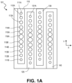
- Figures 1A and 1B are plan views of multi-mode MUT arrays with circular transducer elements.
- Figure 1A is a plan view of a MUT array 101, in accordance with an embodiment.
- the array 101 includes a plurality of electrode rails 110, 120, 130, 140 disposed over an area defined by a first dimension, x and a second dimension y , of a substrate 101.
- Each of the drive/sense electrode rails (e.g., 110) is electrically addressable independently from any other drive/sense electrode rails (e.g., 120 or 130) and are functionally, separate channels of the array 101.
- Each channel has a characteristic frequency response that is a composite of the responses from individual transducer elements within the channel.
- a drive/sense electrode for each channel is electrically coupled in parallel to each element.
- transducer elements 111A-116A and 111B-116B, etc. are coupled together to be electrically driven by the drive/sense electrode rail 110.
- all transducer elements e.g., 121A
- any number of transducer elements may lumped together within a channel, as a function of the membrane diameter, element pitch and substrate area allocated for each channel.
- each channel includes three adjacent elements in a first (y) dimension (e.g., elements 111A 1 , 111A 2 , and 111A 3 ). Within this first dimension, all elements have the same membrane size (i.e., same diameter).
- At least one membrane dimension varies across elements of a same channel of the apparatus.
- the circular membrane diameters vary along at least one dimension of the substrate (e.g., y-dimension) such that each channel includes a range of membrane sizes.
- each channel includes the same number of membranes of a particular size and a same number of different sizes.
- resonance frequency is a function of membrane size (with a higher frequency associated with smaller membrane size)
- each channel can be expected to have very nearly the same frequency response.
- channels with differing element populations i.e., a different number of membrane sizes, different number of membranes of a particular size, or different spatial arrangements over the substrate
- the membranes of differing size within a given channel are spatially arranged on the substrate to avoid destructive interaction between the membranes. It has been found that varying membrane size in a continuous, smooth, and/or incremental manner over one or more substrate dimension advantageously reduces destructive interaction stemming from phase mismatch between membranes of drastically different size.
- resonance phase is maintained across the element population with nearest neighboring elements having similar sized membranes such that the change in membrane size over a given distance does not exceed a particular threshold (e.g., less than 10% change in circular membrane diameter between nearest neighbors, advantageously less than 5%, and most advantageously less than 2%). This approach ensures that every element is surrounded by resonators with similar enough resonance frequency (and therefore phase spectrum) to avoid a destructive interaction.
- Too drastic of a change in membrane size can result in a phase relationship between adjacent membranes that induces a notch in the frequency response of the channel.
- the action of an aggressor/offender membrane may locally push, or pile up, the transmission media over the victim membrane (e.g., a nearest neighbor or otherwise proximal to the offender), increasing effective membrane mass of the second membrane at inopportune times with respect to the victim membrane's phase and thereby dampen or retard performance of the victim element. If such acoustic dampening (or transmission media dampening) is severe, an undesirable zero crossing can occur under operating conditions inducing multiple modes of oscillation.
- transducer element 111A a first size (e.g., smallest diameter membrane) is adjacent to element 112A of a second size (e.g., next larger diameter membrane) with the membrane size gradually increasing in a step-wise manner through a first series of elements with ever increasing membrane size (e.g., 114A, 115A, 116A) and then a second series with stepwise decreasing size back to the smallest diameter.
- a first size e.g., smallest diameter membrane
- a second size e.g., next larger diameter membrane
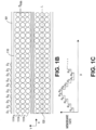
- membrane diameter similarly increases incrementally from D 1 , D 2 , D 3 , D 4 , and D 5 , and then decreases incrementally from a second membrane with radius D 5 , to a second with D 4 , etc., back down to a second membrane with D 1 .
- the set of membranes consecutively spanning the diameters D 1 -D 5 , and D 5 -D 1 forms a repeating unit (RU) that is continued over the length of the channel in the x-dimension.
- RU repeating unit
- both of the spatial arrangements depicted in Figure 1A and Figure 1B ensure each element with the channel population is adjacent to another element of the same size or of a next smallest or next largest size for any number of different membrane sizes (e.g., three, four, or five different sizes depicted in Figure 1B , etc.).
- the spatial density of all membrane sizes within the RU of Figure 1B is advantageously equal with two membranes of every size, or "type.”
- transducer element membrane size within a channel of an array is a cyclic function of at least one dimension of the substrate.
- Figure 1C is a graph depicting a generalized one-dimensional spatial arrangement of transducer membrane sizes that follows a cyclic function, in accordance with an embodiment of a multi-mode MUT array.
- the frequency of the cyclic size variation is limited by the phase matching particular to the mechanical characteristics of the MUT as well as the transmission media and therefore may vary with implementation.
- the amplitude of the cyclic function associated with the maximum and minimum size of the membranes is sufficiently large that the difference between the membranes of maximum and minimum size within the RU is larger than the difference in size between any two adjacent membranes.
- the range between largest and smallest membrane size may be selected to ensure at least two modes of oscillation are induced within the RU by one or more given electrical drive signal while the increment in size between adjacent membranes may be selected to ensure all transducer elements contribute to a response curve maintaining a 3dB bandwidth.
- Corresponding minimum and maximum membrane sizes would then have at least both a 1 st and 2 nd order harmonic (and potentially 3 rd and higher orders to a lesser extent) induced within a channel.
- a range of 20-150 ⁇ m would be typical of membrane dimensions for MHz frequency responses from a transducer having the general structure described in the context of Figures 2A-2C , and an increment of 1-10 ⁇ m would typically provide sufficient response overlap.
- the five membrane sizes could correspond to diameters cycling between 100 and 140 ⁇ m in increments of 10 ⁇ m.
- Figure 1B further illustrates a multiplicity of membranes of one size arrayed in a second dimension of the substrate (e.g., y-dimension where membranes 111A 1 , 111A 2 and 111A 3 are all of the same diameter).
- the embodiment depicted in Figure 1B provides an advantageously higher fill factor than the embodiment depicted in Figure 1A and concomitantly higher gain as the spatial density of each membrane size is greater in Figure 1B .
- a same minimum space S min is maintained between membranes of a same size, regardless of their size.
- a center row of the membranes in the channel e.g., membrane 111A 2 have their centers aligned on the channel axis L with centers of the adjacent membrane rows being one diameter plus one minimum space S min from the channel axis L .
- Multi-mode array architecture may also be implemented with membranes of geometries other than circular/spheroidal.
- Figure 1D is a plan view of a multi-mode MUT array with ellipsoidal transducer elements, in accordance with an embodiment.
- ellipsoidal membranes are more readily driven into higher modes of oscillation as function of the disparity between the semi-principal axis B, C .
- mode shapes can be readily split into more distinct modes having separated resonant frequencies.
- piezoelectric membranes having different semi-principal axis dimensions provides an extra degree of freedom for shaping the frequency response of the transducer elements in a channel.
- at least first and second semi-principal axes are sufficiently different lengths to provide a plurality of separate resonant frequencies (modes).
- the spatial arrangement of ellipsoidal membranes follows the same heuristics described in the context of the circular membranes, but with the exemplary ellipsoidal embodiment depicted in Figure 1D , membrane dimensions are varied in both x and y dimensions within a channel population. As shown, only the length of a first semi-axis (e.g., B ) is changed over a first dimension of a substrate while only the length of the second semi-axis (e.g., C ) is changed over a second dimension of the substrate within a channel.
- a first semi-axis e.g., B
- the second semi-axis e.g., C
- each axis is incrementally increased (and/or decreased) across one of the array dimensions to achieve a range of sizes within an RU that is greater than the difference in sizes between any two adjacent membranes.
- the B axis increments from B 1 , up to B 5 , and then back down to B 1 for elements 1010AA, 1010AE, 1010JA, respectively, along one dimension of the array (e.g., the y-axis of the substrate 101).
- the column or row comprising 1010AB-101JB and the column or row comprising 1010AC-1010JC have the same B axis increment as for the 1010AA-101JA column/ row.
- the C axis increments with each element along a second dimension of the array (e.g., along the x-axis of the substrate 101) such that all elements of the row comprising 1010AA-1010JA are dimensioned to have an axis equal to C 1 .
- all elements of the row comprising 1010AB-1010JB are dimensioned to have an axis equal to C 2
- all elements of the row comprising 1010AC-1010JC are dimensioned to have an axis equal to C 3 .
- each transducer element of the dual-mode MUT array includes a piezoelectric membrane.
- the piezoelectric membrane may be a spheroid with curvature in a third (z) dimension to form a dome (as further illustrated by Figure 2A ), or a dimple (as further illustrated in Figure 2B ).
- Planar membranes are also possible, as further illustrated in Figure 2C .
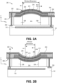
- exemplary micromachined (i.e., microelectromechanical) aspects of individual transducer elements are briefly described. It is to be appreciated that the structures depicted in Figures 2A-2C are included primarily as context for particular aspects of the present invention and to further illustrate the broad applicability of the present invention with respect to transducer element structure.
- a convex transducer element 202 includes a top surface 204 that during operation forms a portion of a vibrating outer surface of the pMUT array 100.
- the transducer element 202 also includes a bottom surface 206 that is attached to a top surface of the substrate 101.
- the transducer element 202 includes a convex or dome-shaped piezoelectric membrane 210 disposed between a reference electrode 212 and a drive/sense electrode 214.
- the piezoelectric membrane 210 can be formed by depositing (e.g., sputtering) piezoelectric material particles in a uniform layer on a profile-transferring substrate (e.g., photoresist) that has a dome formed on a planar top surface, for example.
- a profile-transferring substrate e.g., photoresist
- An exemplary piezoelectric material is Lead Zirconate Titanate (PZT), although any known in the art to be amenable to conventional micromachine processing may also be utilized, such as, but not limited to polyvinylidene difluoride (PVDF) polymer particles, BaTiO 3 , single crystal PMN-PT, and aluminum nitride (AlN).
- PVDF polyvinylidene difluoride
- BaTiO 3 single crystal PMN-PT
- AlN aluminum nitride
- the drive/sense electrode and reference electrode 214, 212 can each be a thin film layer of conductive material deposited (e.g., by PVD, ALD, CVD, etc.) on the profile-profile transferring substrate.
- the conductive materials for the drive electrode layer can be any known in the art for such function, such as, but not limited to, one or more of Au, Pt, Ni, Ir, etc.), alloys thereof (e.g., AuSn, IrTiW, AuTiW, AuNi, etc.), oxides thereof (e.g., IrO 2 , NiO 2 , PtO 2 , etc.), or composite stacks of two or more such materials.
- the transducer element 202 can optionally include a thin film layer 222, such as silicon dioxide that can serve as a support and/or etch stop during fabrication.
- a dielectric membrane 224 may further serve to insulate the drive/sense electrode 214 from the reference electrode 212.
- Vertically-oriented electrical interconnect 226 connects the drive/sense electrode 214 to drive/sense circuits via the drive/sense electrode rail 110.
- a similar interconnect 232 connects the reference electrode 212 to a reference rail 234.
- the support 236 may be of any conventional material, such as, but not limited to, silicon dioxide, polycrystalline silicon, polycrystalline germanium, SiGe, and the like. Exemplary thicknesses of support 236 range from 10-50 ⁇ m and exemplary thickness of the membrane 224 range from 2-20 ⁇ m.
- FIG. 2B shows another example configuration for a transducer element 242 in which structures functionally similar to those in transducer element 202 are identified with like reference numbers.
- the transducer element 242 illustrates a concave piezoelectric membrane 250 that is concave in a resting state.
- the drive/sense electrode 214 is disposed below the bottom surface of the concave piezoelectric membrane 250, while the reference electrode 212 is disposed above the top surface.
- a top protective passivation layer 263 is also shown.
- FIG. 2C shows another example configuration for a transducer element 282 in which structures functionally similar to those in transducer element 202 are identified with like reference numbers.
- the transducer element 282 illustrates a planar piezoelectric membrane 290 that is planar in a resting state and unlike the element 202, 242, operates in bending mode and therefore further employs a membrane 275 (typically of silicon).
- the drive/sense electrode 214 is disposed below the bottom surface of the planar piezoelectric membrane 290, while the reference electrode 212 is disposed above the top surface.
- An opposite electrode configuration from that depicted in each of Figures 2A-2C is also possible.
- Figures 3A and 3B are cross-sectional schematics of a transducer element undergoing first and second modes of oscillation, in accordance with the invention.
- Figures 4A and 4B are frequency response graphs illustrating first and second resonant frequency bands associated with the first and second modes of oscillation depicted in Figures 3A and 3B , in accordance with the invention.
- membranes within an array are induced into a first mode of vibration or oscillation having a characteristic first resonant frequency.
- membranes within the array are induced into a second mode of vibration associated with a second resonant frequency, greater than that of the first resonant frequency. Both a first and second frequency band is then associated with a given population of different membrane sizes.
- Figure 3A depicts, a cross-sectional view of a membrane 350 (which may be a piezoelectric material with planar, domed, or a cavity in a resting state) supported by supports 236 and driven by drive sense/electrode 312 to provide a first mode of vibration when the drive sense/electrode pair 312 receives a time varying voltage drive signal.
- the membrane oscillates in a second resonant as a result of a drive signal. Because the second mode of vibration is of a higher frequency (e.g., 2x) the fundamental, or first, mode of vibration, higher frequency regimes may be achieved in the higher mode.
- two wide bands in the frequency response may be formed (e.g., first band and a second band at about twice the frequency of the first band).
- advantageous mode shapes are the (0,1) mode, (0,2) mode, (0,3) mode in which the number of nodal diameter is 0.
- FIGs 4A and 4B are plots of performance metrics for the MUTs of Figures 3A and 3B , in accordance with embodiments.
- a drive signal generator is to drive a first electrical signal to excite a first resonant mode (f n1 ) of the membrane 350 more than a second resonant mode (f n2 ).
- the drive signal generator induces or excites the second resonant mode (f n2 ) of the membrane 350 more than the first resonant mode (f n1 ).
- Operation in either the first or high mode may be determined by at least a drive signal pulse width, and/or pulse shape, along with the membrane size and shape (e.g., circular vs. elliptical).
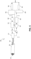
- FIG. 5 is a functional block diagram of an ultrasonic transducer apparatus 500 that employs a multi-mode MUT array, in accordance with an embodiment of the present invention.
- the ultrasonic transducer apparatus 500 is for generating and sensing pressure waves in a medium, such as water, tissue matter, etc.
- the ultrasonic transducer apparatus 500 has many applications in which imaging of internal structural variations within a medium or multiple media is of interest, such as in medical diagnostics, product defect detection, etc.
- the apparatus 500 includes at least one multi-mode MUT array 516, which may have any of the multi-mode MUT array element designs described herein having any of the transducer element and element population attributes described.
- the MUT array 516 is a MUT housed in a handle portion 514 which may be manipulated by machine or by a user of the apparatus 500 to change the facing direction and location of the outer surface of the MUT array 516 as desired (e.g., facing the area(s) to be imaged).
- Electrical connector 520 electrically couple channels of the MUT array 516 to a communication interface external to the handle portion 514.
- the apparatus 500 includes a signal generating means, which may be any known in the art, coupled to the MUT array 516, for example by way of electrical connector 520.
- the signal generating means is to provide an electrical drive signal to the drive/sense electrode of each channel in the array 516.
- the signal generating means is to apply an electrical drive signal to cause the piezoelectric transducer element populations to resonate at frequencies between 1MHz and 40MHz.
- the signal generating means includes a de-serializer 504 to de-serialize control signals that are then de-multiplexed by demux 506.
- the exemplary signal generating means further includes a digital-to-analog converter (DAC) 508 to convert the digital control signals into driving voltage signals for the individual transducer element channels in the MUT array 516.
- DAC digital-to-analog converter
- Respective time delays can be added to the individual drive voltage signal by a programmable time-delay controller 510 to beam steer, create the desired beam shape, focus, and direction, etc.
- Coupled between the pMUT channel connector 520 and the signal generating means is a switch network 512 to switch the MUT array 516 between drive and sense modes.
- the apparatus 500 includes a signal collecting means, which may be any known in the art, coupled to the MUT array 516, for example by way of electrical connector 520.
- the signal collecting means is to collect and filter an electrical sense signal from the drive/sense electrode channels in the MUT array 516.
- an analog to digital converter (ADC) 530 is a receiver of voltage signals from channels the array 516, which are converted to digital signals. The digital signals may then be stored to a memory (not depicted) or passed directly to a signal processing means.
- An exemplary signal processing means includes a data compression unit 526 to compress the digital signals.
- a multiplexer 528 and a serializer 502 may further process (e.g., filter based on frequency, etc.) the received signals before relaying them to a memory, other storage, or a downstream processor, such as an image processor that is to generate a graphical display based on the received signals.
- FIG. 6 is a flow diagram further depicting manners of operating a multi-mode MUT array, in accordance with embodiments.
- a multi-mode MUT array 601 is operated in at least one of three capacities.
- the multi-mode MUT array 601 is driven at operation 605 to induce the first and higher order modes concurrently to achieve a super-wide, multi-resonant frequency bandwidth.
- the multi-mode MUT array 601 is then further employed to sense over this entire bandwidth at operation 610.
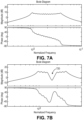
- Figures 7A-7B describe this first manner of operation.
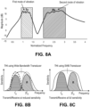
- the multi-mode MUT array 601 is driven to primary induce a first component of the multi-resonant frequency bandwidth for transmission at operation 620, while a second component the bandwidth is sensed at operation 625.
- Figures 8A-8C further describe this second manner of operating.
- different channels of the multi-mode MUT array 601 are driven to induce different components of the multi-resonant frequency bandwidth (i.e., first and second resonant frequency bands) at operations 630, 633, and to sense the different components of the multi-resonant frequency bandwidth with the different channels at operation 636 and 639.
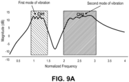
- This multi-signal or multi-channel mode is further described in the context of Figures 9A-9C .
- the first and second resonant modes overlap.
- Third and higher modes may also overlap with the bands of the next-higher and next-lower order.
- the highest resonance frequency of a first resonance frequency band associated with the first order mode is higher than the lowest resonance frequency of the second resonance frequency band, associated with the second order mode, as is depicted in the phase and magnitude graphs of Figure 7A .
- the membrane population is designed, for example by controlling membrane size and layout as described in the context of Figures 1A-1D . Membrane effective mass, effective stiffness may also be controlled in the effort to avoid, or at least mitigate, destructive phasing.
- Overlap between the highest resonance frequency of the first mode (associated with smallest membrane element) and the lowest resonance frequency of the second mode (associated with largest membrane element) may then merge both spectrum bands and extend the bandwidth of the array to at least 120% -6dB fraction bandwidth (i.e., the -6db bandwidth/center frequency).
- Figure 7B is a modeled frequency response for a MUT array suffering some deconstructive phasing between first and second vibrational modes. For membranes of a fixed, uniform size for example, phase crosses zero between the first and second modes of vibration resulting a notch in the frequency band at least significant as the notch 720 in Figure 7B .
- the resonant mode frequency bands can be fully merged by employing the gradual variation of element sizes depicted in Figure 1B , for example.
- a drive signal applied to a population of membranes of differing size within a same channel may induce both a first mode of oscillation in one or more membrane and also induce a second mode of oscillation in one or more other membranes.
- the same bandwidth may be utilized in the sense cycle of the super-wide bandwidth pressure transducer.
- drive circuitry coupled to the multi-mode MUT array includes a signal generator that drives at least some of the transducer elements of a given channel with a first electrical signal that induces at least the first frequency band (e.g., lower band).
- the pulse width and shape may deviate from that employed for super-wide bandwidth embodiments to induce only a portion of the multi-resonant frequency band.
- Sense circuitry includes a signal receiver coupled to the multi-mode MUT array to receive a second electrical signal from at least some of the transducer elements that includes a component from the second frequency band, which may be extracted with an appropriate band pass filter.
- the resonance frequency bands may either overlap, or not. Where the bands do overlap, for example where the membrane dimensioning and layout follow the example of Figure 1B and are also suitable for super-wide bandwidth operation, some membranes may oscillate in the second mode within the transmit frequency band and some membranes may oscillate in the first mode within the receive frequency band such that the Tx and Rx bands are not exclusive one resonant mode.
- the second mode of operation illustrated in Figure 8A is well-suited to the technique of tissue harmonic imaging (THI) where the first band of lower frequency vibration and the second band of higher frequency vibration are used without suffering the limitations in gain typical of lower bandwidth transducers.
- THI tissue harmonic imaging
- signal penetration in soft tissue increases as the transmit frequency is decreased, but there is a concomitant decrease in image resolution.
- As an ultrasound wave propagates through the target media a change occurs in the shape and frequency of the transmitted signal due nonlinear distortion of the acoustic wave. Harmonic waves are generated within the media and build up with depth.
- the harmonic wave frequencies are higher integer multiples of the transmitted frequency much like the overtones of a musical notes.
- Current THI technology uses only the second harmonic (twice the transmitted frequency) for imaging.
- a transmit frequency of 3.0 MHz. which may provide maximum penetration, will return a harmonic frequency of 6.0 MHz.
- the returning higher frequency signal travels only in one direction to the probe.
- the advantages of high frequency imaging and the one-way travel effect include decreased reverberation, beam aberration, and side lobes, as well as increased resolution and cystic clearing.
- transducer bandwidth may be a limiting factor for THI because the transducer must be both an efficient transmitter at one frequency and an efficient receiver at the second harmonic.
- transducer bandwidths e.g., approximately 70% - 80% -6 dB fractional bandwidth
- the transmitted center frequency is typically set to 2/3 of the center frequency while the harmonic receive frequency is set to 4/3 of the center frequency.
- destructive interaction between elements of a channel may limit bandwidth so that gain (sensitivity) is reduced .
- the greater bandwidth of the multi-resonant mode MUT which includes both the first resonant mode and second resonant modes of a channel and encompassing the fundamental (f 0 ) and 2f 0 frequencies naturally enable a very efficient THI transmitter and receiver, respectively. Therefore, THI can be advantageously implemented with the multi-mode MUT arrays having a combination of various membrane sizes (e.g., as depicted in Figure 1B ).
- a multi-mode MUT array is operated in a third manner to further leverage the bandwidth associated with the multiple resonant modes by apportioning it across different channels of an ultrasonic transducer.
- a first frequency band such as a lower frequency band associated primarily with a fundamental oscillation is employed in a first channel of the transducer while a second frequency band, such a higher frequency band associated primarily with a second or third order harmonic, is employed in a second channel to achieve a high sampling rate.
- a first electrical signal of a first pulse shape and/or width may induce a fundamental oscillation in one or more of the membranes in a first channel while a second electrical signal of a second pulse shape and/or width (e.g., short) may induce a higher order oscillation in one or more of the membranes in a second channel.
- a second electrical signal of a second pulse shape and/or width e.g., short
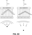
- the modeled spectrum depicted in Figure 9A is provided.
- the first and second channel signals are filtered with an appropriately different band pass, for example to extract the low frequency band from the first channel and the high frequency band from the second channel.
- Multi-channel operation may facilitate both a near field and far field focus zone (i.e., multi-depth) imaging at high sampling rates.
- a near field and far field focus zone i.e., multi-depth
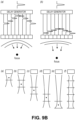
- Such a technique is in contrast to a conventional multi-zone focus technique, illustrated in Figure 9B , where limited scanning rate leads to distorted images of fast moving objects such as the heart and flowing blood.
- scan rate is governed by the need to wait for the information to be returned from the most distant location before the next pulse is transmitted.
- a delay generator implements a first delay signature across a plurality of transducer channels. Then, a second pulse with different delay signature associated with a second depth is then sent.
- each frequency band may be employed in an independent imaging channel.
- Each channel can be excited by an excitation waveform at its associated frequency, such as a pulse with the duration of (T ⁇ 1/2f i ) or chirp waveforms.
- the receive signal can be analyzed into various channels using corresponding band-pass filters or by various demodulation techniques. Consequently, the frame rate can be improved proportionally to the number of channels.
- the proposed multi-channel operational mode can efficiently implement a multiple focus zone technique where high frequency channels associated with a first excitation waveform of high frequency (short pulse) are used for a near field zone and focused accordingly (smaller focus length) to provide a high resolution image.
- the LF (low frequency) channel or channels
- this approach provides the fast imaging rate of high-frequency transducers, deep penetration of low frequency transducers and improved effective lateral resolution over the entire image depth.
- one of the technical challenges to implementing multi-mode MUT embodiments described herein include destructive interference between membranes of a same channel.
- Frequency shaping with various sizes of vibrating membranes may be done to improve the bandwidth of the MUT and/or tailor the bandwidth to the particular modes of operation describe herein.
- the design task is then similar to designing a broadband bandpass filter by employing n first-order filters.
- frequency shaping can be tuned by geometry using lithography as the shape of the frequency response is a function of the set of diaphragm diameters, several parameters including the effective stiffness, effective mass, natural resonance frequencies, the effective acoustic impedance and the coupling between elements are all strong functions of the membrane diameter. Consequently, the frequency spectrum of the transducer is a very complex function of the membrane diameters rendering the frequency shaping a potentially cumbersome and complex procedure in practice.
- a frequency response of a MUT array is optimized from a modeled nominal dimension by performing a sensitivity analysis on one or more mask levels of a MUT device.
- sensitivity analysis is performed using a single mask level that defines an area of contact between an electrode and material of the transducer membrane.
- the single mask level is a dielectric window layer which defines a dimensioned opening over the membrane material through which an electrode makes contact.
- Figure 2A, 2B , and 2C for example illustrate how a window dimension defines an opening in the dielectric membrane 224 (e.g., oxide) disposed between the piezoelectric membrane 210 and the drive/sense electrode 212.
- this dielectric window is another parameter which primarily affects the amplitude of various mode shapes without significantly changing mode shapes and frequencies. Furthermore, it is expected to only slightly change the effective mass, effective stiffness and the effective acoustic impedance. As such, in embodiments a final frequency response a fine tuned based on the optimization of oxide window dimension.
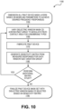
- FIG. 10 is a flow diagram illustrating a method 1100 of optimizing a frequency shape from a population of membranes having differing membrane sizes by performing a sensitivity analysis of the dielectric windows size determined through experiment, potentially with only one fabrication run and one turn of a single mask layer (the window mask).
- the method 1100 begins at operation 1150 with dimensioning all mask layers of a PMUT device based on modeling parameters to achieve a desired nominal frequency response, or responses.
- the dielectric window mask CD is varied across the PMUT array channels to modulate the piezoelectric contact area for n membrane types (sizes).
- n membrane types sizes
- each array can be designed as a sensitivity matrix by splitting these channels into n + 1 groups: one control set estimated by the model and variations of the control set in which the oxide window of only one type of membrane per variation is changed by predefined value (2um-20um), as is further illustrated for 5 variations in Figure 11 .
- the circular band 1110 represents a window CD shrink, and for the channel associated with electrode rail 110, only the largest membrane element is modulated (shrunk) by the predetermined amount, while membranes of a different nominal size have a window size varied for the other four treatments depicted.
- the PMUT device if fabricated using the mask set that includes the experimental window dimensioning.
- Channel responses (further illustrated in Figure 11 ) are then measured for each window size variation from the fabricated device at operation 1180 ( Figure 10 ). These responses are then compared to responses associated with a nominal (modeled) dimension to generate the sensitivity terms ( ⁇ y ⁇ x , where x is window size and y is frequency response).
- Optimal sizing of the window for each membrane size classification is then determined based on the sensitivity analysis to arrive at the desired final frequency response.
- a final mask set is then defined based on these optimal mask dimension determine for each different membrane size employed in the array at operation 1190.
- a second iteration of the sensitivity analysis may performed, as an option.
Landscapes
- Engineering & Computer Science (AREA)
- Mechanical Engineering (AREA)
- Health & Medical Sciences (AREA)
- Surgery (AREA)
- Life Sciences & Earth Sciences (AREA)
- Medical Informatics (AREA)
- Animal Behavior & Ethology (AREA)
- Nuclear Medicine, Radiotherapy & Molecular Imaging (AREA)
- Biomedical Technology (AREA)
- Heart & Thoracic Surgery (AREA)
- Physics & Mathematics (AREA)
- Molecular Biology (AREA)
- Otolaryngology (AREA)
- General Health & Medical Sciences (AREA)
- Public Health (AREA)
- Veterinary Medicine (AREA)
- Plasma & Fusion (AREA)
- Manufacturing & Machinery (AREA)
- Transducers For Ultrasonic Waves (AREA)
- Ultra Sonic Daignosis Equipment (AREA)
- Investigating Or Analyzing Materials By The Use Of Ultrasonic Waves (AREA)
Claims (14)
- Vorrichtung zum Erzeugen und Erfassen von Druckwellen in einem Medium, wobei die Vorrichtung Folgendes umfasst:ein mikrobearbeitetes Ultraschallwandler-Array, MUT-Array, (101), das einen ersten Kanal umfasst, der eine Mehrzahl von Wandlerelementen (111A, 112A, 113A, 114A, 115A, 116A, 115B, 114B, 113B, 112B, 111B) enthält, wobei jedes Wandlerelement (202) eine Membran (210), eine einzelne Ansteuer-/Abtastelektrode (214) und eine Referenzelektrode (212) enthält, wobei die Mehrzahl von Wandlerelementen eine erste Reihe benachbarter Wandlerelemente (111A, 112A, 113A, 114A, 115A, 116A), dann eine zweite Reihe benachbarter Wandlerelemente (115B, 114B, 113B, 112B, 111B) umfasst, und wobei jede aufeinanderfolgende Membran der ersten Reihe einen zunehmend größeren jeweiligen Durchmesser aufweist und jede aufeinanderfolgende Membran der zweiten Reihe einen zunehmend kleineren jeweiligen Durchmesser aufweist;und eine Ansteuer- und Abtastschaltung, die dazu konfiguriert ist, das MUT-Array zu betreiben, wobei die Ansteuer- oder Abtastschaltung dazu konfiguriert ist, einen von mindestens zwei Modi des MUT-Arrays zu induzieren, wobei die mindestens zwei Modi einen ersten Modus, der die erste Mehrzahl von Schwingungsmodi enthält, und einen zweiten Modus, der die zweite Mehrzahl von Schwingungsmodi enthält, umfassen,wobei die Ansteuerschaltung einen Signalgenerator (504, 506, 508) enthält, der mit dem MUT-Array gekoppelt und dazu konfiguriert ist, mindestens einige der Wandlerelemente mit einem ersten elektrischen Signal anzusteuern, das mindestens eine oder mehrere der ersten Resonanzfrequenzen innerhalb des ersten Frequenzbands induziert; undwobei die Abtastschaltung einen Signalempfänger (514) enthält, der mit dem MUT-Array gekoppelt und dazu konfiguriert ist, ein zweites elektrisches Signal, das eine Komponente aus dem zweiten Frequenzband enthält, von mindestens einigen der Wandlerelemente zu empfangen;dadurch gekennzeichnet, dassfür jedes Wandlerelement der Mehrzahl von Wandlerelementen:die Membran des Wandlerelements so dimensioniert ist, dass sie jeweils durch eine jeweilige Membran der Mehrzahl von Wandlerelementen in einen jeweiligen ersten Schwingungsmodus einer ersten Mehrzahl von Schwingungsmodi eintritt, wobei die erste Mehrzahl von Schwingungsmodi jeweils einer Lösung einer jeweiligen Bessel-Funktion entspricht, wobei die erste Mehrzahl von Schwingungsmodi jeweils einer jeweiligen Frequenz (fn1) erster Resonanzfrequenzen in einem ersten Frequenzband entspricht; unddie Membran des Wandlerelements so dimensioniert ist, dass sie durch eine jeweilige Membran der Mehrzahl von Wandlerelementen in einen jeweiligen zweiten Schwingungsmodus einer zweiten Mehrzahl von Schwingungsmodi eintritt, wobei die zweite Mehrzahl von Schwingungsmodi jeweils einer Lösung einer jeweiligen Bessel-Funktion entspricht, wobei die zweite Mehrzahl von Schwingungsmodi jeweils einer jeweiligen Frequenz (fn2) zweiter Resonanzfrequenzen in einem zweiten Frequenzband entspricht, wobei die erste Mehrzahl von Schwingungsmodi und die zweite Mehrzahl von Schwingungsmodi jeweils unterschiedliche Schwingungsmodi aufweisen, und wobei eine oder mehrere der zweiten Resonanzfrequenzen größer als jede der ersten Resonanzfrequenzen ist.
- Vorrichtung nach Anspruch 1, wobei eine Mitte des zweiten Frequenzbands etwa doppelt so groß ist wie die Mitte des ersten Frequenzbands, und wobei eines oder mehrere des ersten Frequenzbands und des zweiten Frequenzbands Resonanzfrequenzen aufweisen, die einem dritten, oder höheren, Modus des MUT-Arrays entsprechen.
- Vorrichtung nach Anspruch 2, wobei eine Resonanzfrequenz, die einem der ersten Mehrzahl von Schwingungsmodi entspricht, höher ist als eine niedrigste Resonanzfrequenz, die einem der zweiten Mehrzahl von Schwingungsmodi entspricht.
- Vorrichtung nach Anspruch 1, wobei das MUT-Array ein piezoelektrischer MUT, pMUT, mit Wandlerelementen des Arrays ist, die einen Bereich von piezoelektrischen Membrangrößen aufweisen, und wobei das erste Frequenzband eine Funktion des Bereichs von Membrangrößen ist.
- Vorrichtung nach Anspruch 1, wobei das erste elektrische Signal sowohl die erste Mehrzahl von Schwingungsmodi als auch die zweite Mehrzahl von Schwingungsmodi induziert; und wobei das zweite elektrische Signal Komponenten sowohl aus dem ersten Frequenzband als auch aus dem zweiten Frequenzband enthält.
- Vorrichtung nach Anspruch 1, wobei das erste elektrische Signal eine Impulsbreite und -form aufweist, die von der ersten Mehrzahl von Schwingungsmodi über die zweite Mehrzahl von Schwingungsmodi nur die erste Mehrzahl von Schwingungsmodi induziert; und wobei der Signalempfänger dazu dient, eine Komponente des zweiten elektrischen Signals, die dem zweiten Frequenzband zugeordnet ist, aus einer anderen Komponente des zweiten elektrischen Signals, die dem ersten Frequenzband zugeordnet ist, zu filtern.
- Vorrichtung nach Anspruch 1, wobei Membranen unterschiedlicher Größe räumlich auf einem Substrat angeordnet sind, um eine destruktive Wechselwirkung zwischen Membranen in einem gleichen Kanal und ein Übersprechen zwischen Membranen benachbarter Kanäle zu vermeiden.
- Vorrichtung nach Anspruch 7, wobei mindestens eine Abmessung der Membranen zwischen einem minimalen und einem maximalen Wert variiert, der einen Bereich überspannt, der größer ist als ein Unterschied in der Abmessung zwischen zwei benachbarten Membranen.
- Vorrichtung nach Anspruch 8, wobei die jeweiligen Größen der Membranen über eine erste Reihe von mindestens drei benachbarten Membranen schrittweise zunehmen und über eine zweite Reihe von mindestens drei benachbarten Membranen schrittweise abnehmen, und wobei die erste und die zweite Reihe beide eine Membran mit maximaler Abmessung und eine Membran mit minimaler Abmessung enthalten.
- Vorrichtung nach Anspruch 9, wobei die jeweiligen Größen der Membranen gemäß einer zyklischen Funktion von mindestens einer Abmessung des Arrays variieren, um zwei von n verschiedenen Membrantypen innerhalb einer Wiederholungseinheit der Kanalpopulation bereitzustellen.
- Verfahren zum Generieren und Abtasten von Druckwellen in einem Medium, wobei das Verfahren Folgendes umfasst:
Ansteuern jeweiliger Elektroden von mindestens einigen einer Mehrzahl von Wandlerelementen (111A, 112A, 113A) eines mikrobearbeiteten Ultraschallwandler-Arrays, MUT-Arrays, (101) mit einem ersten elektrischen Signal, wobei für jedes Wandlerelement (202) des MUT-Arrays:eine Membran (202) des Wandlerelements so dimensioniert ist, dass sie jeweils durch eine jeweilige Membran einer Mehrzahl von Wandlerelementen des MUT-Arrays in einen jeweiligen ersten Schwingungsmodus einer ersten Mehrzahl von Schwingungsmodi eintritt, wobei die erste Mehrzahl von Schwingungsmodi jeweils einer Lösung einer jeweiligen Bessel-Funktion entsprechen,wobei die erste Mehrzahl von Schwingungsmodi jeweils einer jeweiligen Frequenz erster Resonanzfrequenzen in einem ersten Frequenzband entspricht;und die Membran des Wandlerelements so dimensioniert ist, dass sie durch jeweils eine jeweilige Membran der Mehrzahl von Wandlerelementen in einen jeweiligen zweiten Schwingungsmodus einer zweiten Mehrzahl von Schwingungsmodi eintritt, wobei die zweite Mehrzahl von Schwingungsmodi jeweils einer Lösung einer jeweiligen Bessel-Funktion entspricht,wobei die zweite Mehrzahl von Schwingungsmodi jeweils einer jeweiligen Frequenz zweiter Resonanzfrequenzen in einem zweiten Frequenzband entspricht, wobei die erste Mehrzahl von Schwingungsmodi und die zweite Mehrzahl von Schwingungsmodi unterschiedliche jeweilige Schwingungsmodi aufweisen, und wobei eine oder mehr der zweiten Resonanzfrequenzen größer sind als jede der ersten Resonanzfrequenzen,wobei ein erster Kanal des MUT-Arrays die Mehrzahl von Wandlerelementen (111A, 112A, 113A) enthält, wobei jedes Wandlerelement (202) eine Membran (210), eine einzelne Ansteuer-/Abtastelektrode (214) und eine Referenzelektrode (212) enthält, wobei die Mehrzahl von Wandlerelementen eine erste Reihe benachbarter Wandlerelemente (111A, 112A, 113A, 114A, 115A, 116A) und dann eine zweite Reihe benachbarter Wandlerelemente (115B, 114B, 113B, 112B, 112B, 111B) umfasst, und wobei jede aufeinanderfolgende Membran der ersten Reihe einen immer größer werdenden jeweiligen Durchmesser aufweist und jede aufeinanderfolgende Membran der zweiten Reihe einen immer kleiner werdenden jeweiligen Durchmesser aufweist, wobei das erste elektrische Signal zumindest den jeweiligen ersten Schwingungsmodus induziert, der dem ersten Frequenzband zugeordnet ist; undEmpfangen eines zweiten elektrischen Signals, das mindestens eine oder mehrere der zweiten Resonanzfrequenzen innerhalb des zweiten Frequenzbands enthält, das dem jeweiligen zweiten Schwingungsmodus des MUT-Arrays entspricht, von jeweiligen Elektroden mindestens einiger der Mehrzahl von Wandlerelementen, wobei das zweite Frequenzband eine oder mehrere der zweiten Resonanzfrequenzen aufweist, die größer als jede der ersten Resonanzfrequenzen innerhalb des ersten Frequenzbands sind. - Verfahren nach Anspruch 11, wobei das Ansteuern sowohl Resonanzfrequenzen im ersten Frequenzband als auch Resonanzfrequenzen im zweiten Frequenzband induziert; und wobei das zweite elektrische Signal Komponenten sowohl aus dem ersten als auch dem zweiten Frequenzband enthält.
- Verfahren nach Anspruch 12, wobei erste Resonanzfrequenzen im ersten Frequenzband auf dem ersten Kanal des MUT-Arrays induziert werden und zweite Resonanzfrequenzen im zweiten Frequenzband auf einem zweiten Kanal des Arrays induziert werden; und
wobei Komponenten aus dem ersten Frequenzband vom ersten Kanal gesammelt werden und die Komponenten vom zweiten Frequenzband vom zweiten Kanal gesammelt werden. - Verfahren nach Anspruch 11, wobei das erste elektrische Signal eine Impulsbreite und -form aufweist, die Resonanzfrequenzen im ersten Frequenzband stärker induziert als Resonanzfrequenzen im zweiten Frequenzband, wobei das Verfahren ferner Folgendes umfasst:
Filtern einer Komponente des zweiten elektrischen Signals, die dem zweiten Frequenzband zugeordnet ist, aus derjenigen, die dem ersten Frequenzband zugeordnet ist.
Priority Applications (1)
| Application Number | Priority Date | Filing Date | Title |
|---|---|---|---|
| EP23182469.9A EP4245429B1 (de) | 2012-10-26 | 2013-10-03 | Mikrogefertigte ultraschallwandlerarrays mit mehreren harmonischen modi |
Applications Claiming Priority (3)
| Application Number | Priority Date | Filing Date | Title |
|---|---|---|---|
| US201261718952P | 2012-10-26 | 2012-10-26 | |
| US13/830,251 US9660170B2 (en) | 2012-10-26 | 2013-03-14 | Micromachined ultrasonic transducer arrays with multiple harmonic modes |
| PCT/US2013/063255 WO2014066006A1 (en) | 2012-10-26 | 2013-10-03 | Micromachined ultrasonic transducer arrays with multiple harmonic modes |
Related Child Applications (2)
| Application Number | Title | Priority Date | Filing Date |
|---|---|---|---|
| EP23182469.9A Division EP4245429B1 (de) | 2012-10-26 | 2013-10-03 | Mikrogefertigte ultraschallwandlerarrays mit mehreren harmonischen modi |
| EP23182469.9A Division-Into EP4245429B1 (de) | 2012-10-26 | 2013-10-03 | Mikrogefertigte ultraschallwandlerarrays mit mehreren harmonischen modi |
Publications (3)
| Publication Number | Publication Date |
|---|---|
| EP2912858A1 EP2912858A1 (de) | 2015-09-02 |
| EP2912858A4 EP2912858A4 (de) | 2016-06-29 |
| EP2912858B1 true EP2912858B1 (de) | 2023-08-23 |
Family
ID=50545100
Family Applications (2)
| Application Number | Title | Priority Date | Filing Date |
|---|---|---|---|
| EP23182469.9A Active EP4245429B1 (de) | 2012-10-26 | 2013-10-03 | Mikrogefertigte ultraschallwandlerarrays mit mehreren harmonischen modi |
| EP13848357.3A Active EP2912858B1 (de) | 2012-10-26 | 2013-10-03 | Mikrogefertigte ultraschallwandlerarrays mit mehreren harmonischen modi |
Family Applications Before (1)
| Application Number | Title | Priority Date | Filing Date |
|---|---|---|---|
| EP23182469.9A Active EP4245429B1 (de) | 2012-10-26 | 2013-10-03 | Mikrogefertigte ultraschallwandlerarrays mit mehreren harmonischen modi |
Country Status (6)
| Country | Link |
|---|---|
| US (3) | US9660170B2 (de) |
| EP (2) | EP4245429B1 (de) |
| JP (1) | JP6360487B2 (de) |
| KR (1) | KR20150073964A (de) |
| CN (1) | CN104756521B (de) |
| WO (1) | WO2014066006A1 (de) |
Families Citing this family (120)
| Publication number | Priority date | Publication date | Assignee | Title |
|---|---|---|---|---|
| US9184369B2 (en) | 2008-09-18 | 2015-11-10 | Fujifilm Sonosite, Inc. | Methods for manufacturing ultrasound transducers and other components |
| US9173047B2 (en) * | 2008-09-18 | 2015-10-27 | Fujifilm Sonosite, Inc. | Methods for manufacturing ultrasound transducers and other components |
| WO2012112540A2 (en) * | 2011-02-15 | 2012-08-23 | Fujifilm Dimatix, Inc. | Piezoelectric transducers using micro-dome arrays |
| US9454954B2 (en) * | 2012-05-01 | 2016-09-27 | Fujifilm Dimatix, Inc. | Ultra wide bandwidth transducer with dual electrode |
| US8767512B2 (en) * | 2012-05-01 | 2014-07-01 | Fujifilm Dimatix, Inc. | Multi-frequency ultra wide bandwidth transducer |
| US9660170B2 (en) | 2012-10-26 | 2017-05-23 | Fujifilm Dimatix, Inc. | Micromachined ultrasonic transducer arrays with multiple harmonic modes |
| JP5836537B2 (ja) * | 2013-03-28 | 2015-12-24 | 富士フイルム株式会社 | ユニモルフ型超音波探触子 |
| KR102077741B1 (ko) * | 2013-10-23 | 2020-02-14 | 삼성전자주식회사 | 초음파 변환기 및 이를 채용한 초음파 진단장치 |
| US10107645B2 (en) | 2014-05-30 | 2018-10-23 | Fujifilm Dimatix, Inc. | Piezoelectric transducer device with flexible substrate |
| US9789515B2 (en) | 2014-05-30 | 2017-10-17 | Fujifilm Dimatix, Inc. | Piezoelectric transducer device with lens structures |
| US10022751B2 (en) | 2014-05-30 | 2018-07-17 | Fujifilm Dimatix, Inc. | Piezoelectric transducer device for configuring a sequence of operational modes |
| JP6424507B2 (ja) * | 2014-07-28 | 2018-11-21 | コニカミノルタ株式会社 | 超音波トランスデューサ及び超音波診断装置 |
| EP3109650B1 (de) * | 2015-06-25 | 2020-04-01 | ABB Schweiz AG | Signalhandhabung für unerreichbar gelegene leistungseinrichtung |
| CN108348158B (zh) * | 2015-11-03 | 2022-02-08 | Nrg系统股份有限公司 | 用于野生动物阻吓的宽带超声换能器设备及其使用方法 |
| US10618079B2 (en) | 2016-02-29 | 2020-04-14 | Qualcomm Incorporated | Piezoelectric micromechanical ultrasonic transducers and transducer arrays |
| US10109784B2 (en) * | 2016-03-01 | 2018-10-23 | Qualcomm Incorporated | Sensor device |
| WO2017189435A1 (en) * | 2016-04-24 | 2017-11-02 | Flodesign Sonics, Inc. | Electronic configuration and control for acoustic standing wave generation |
| US11813639B2 (en) | 2016-05-03 | 2023-11-14 | Vanguard International Semiconductor Singapore Pte. Ltd. | Electrode arrangement for a pMUT and pMUT transducer array |
| US10445547B2 (en) | 2016-05-04 | 2019-10-15 | Invensense, Inc. | Device mountable packaging of ultrasonic transducers |
| US10315222B2 (en) | 2016-05-04 | 2019-06-11 | Invensense, Inc. | Two-dimensional array of CMOS control elements |
| US10656255B2 (en) | 2016-05-04 | 2020-05-19 | Invensense, Inc. | Piezoelectric micromachined ultrasonic transducer (PMUT) |
| US10670716B2 (en) | 2016-05-04 | 2020-06-02 | Invensense, Inc. | Operating a two-dimensional array of ultrasonic transducers |
| US10325915B2 (en) | 2016-05-04 | 2019-06-18 | Invensense, Inc. | Two-dimensional array of CMOS control elements |
| US10452887B2 (en) | 2016-05-10 | 2019-10-22 | Invensense, Inc. | Operating a fingerprint sensor comprised of ultrasonic transducers |
| US10441975B2 (en) | 2016-05-10 | 2019-10-15 | Invensense, Inc. | Supplemental sensor modes and systems for ultrasonic transducers |
| US10408797B2 (en) | 2016-05-10 | 2019-09-10 | Invensense, Inc. | Sensing device with a temperature sensor |
| US10632500B2 (en) | 2016-05-10 | 2020-04-28 | Invensense, Inc. | Ultrasonic transducer with a non-uniform membrane |
| US10600403B2 (en) | 2016-05-10 | 2020-03-24 | Invensense, Inc. | Transmit operation of an ultrasonic sensor |
| US10706835B2 (en) | 2016-05-10 | 2020-07-07 | Invensense, Inc. | Transmit beamforming of a two-dimensional array of ultrasonic transducers |
| US11673165B2 (en) | 2016-05-10 | 2023-06-13 | Invensense, Inc. | Ultrasonic transducer operable in a surface acoustic wave (SAW) mode |
| US10539539B2 (en) * | 2016-05-10 | 2020-01-21 | Invensense, Inc. | Operation of an ultrasonic sensor |
| US10562070B2 (en) | 2016-05-10 | 2020-02-18 | Invensense, Inc. | Receive operation of an ultrasonic sensor |
| WO2017200490A1 (en) * | 2016-05-18 | 2017-11-23 | Agency For Science, Technology And Research | Window with noise management and related methods |
| US11712221B2 (en) | 2016-06-20 | 2023-08-01 | Bfly Operations, Inc. | Universal ultrasound device and related apparatus and methods |
| US10856840B2 (en) * | 2016-06-20 | 2020-12-08 | Butterfly Network, Inc. | Universal ultrasound device and related apparatus and methods |
| US10618078B2 (en) * | 2016-07-18 | 2020-04-14 | Kolo Medical, Ltd. | Bias control for capacitive micromachined ultrasonic transducers |
| US9900707B1 (en) | 2016-11-29 | 2018-02-20 | Cirrus Logic, Inc. | Biasing of electromechanical systems microphone with alternating-current voltage waveform |
| GB2557367A (en) * | 2016-11-29 | 2018-06-20 | Cirrus Logic Int Semiconductor Ltd | Mems device |
| US11039814B2 (en) * | 2016-12-04 | 2021-06-22 | Exo Imaging, Inc. | Imaging devices having piezoelectric transducers |
| CN106862045A (zh) * | 2017-01-06 | 2017-06-20 | 中北大学 | 收发性能平衡的微机电超声换能器面阵探头及其制备方法 |
| CN106865483A (zh) * | 2017-01-06 | 2017-06-20 | 中北大学 | 医用微电容超声换能器面阵探头及其制备方法 |
| CN106744642A (zh) * | 2017-01-06 | 2017-05-31 | 中北大学 | 收发平衡的宽频带混合式超声换能器面阵探头及制备方法 |
| JP6801469B2 (ja) * | 2017-01-20 | 2020-12-16 | コニカミノルタ株式会社 | 超音波診断装置 |
| US10891461B2 (en) | 2017-05-22 | 2021-01-12 | Invensense, Inc. | Live fingerprint detection utilizing an integrated ultrasound and infrared sensor |
| US10474862B2 (en) | 2017-06-01 | 2019-11-12 | Invensense, Inc. | Image generation in an electronic device using ultrasonic transducers |
| US10643052B2 (en) | 2017-06-28 | 2020-05-05 | Invensense, Inc. | Image generation in an electronic device using ultrasonic transducers |
| EP3424602A1 (de) * | 2017-07-04 | 2019-01-09 | Koninklijke Philips N.V. | Ultraschallschnittstellenelement und verfahren |
| JP2019016912A (ja) * | 2017-07-06 | 2019-01-31 | コニカミノルタ株式会社 | 超音波トランスデューサーアレイ、超音波探触子および超音波診断装置 |
| GB2565375A (en) * | 2017-08-11 | 2019-02-13 | Cirrus Logic Int Semiconductor Ltd | MEMS devices and processes |
| KR102475893B1 (ko) * | 2017-09-19 | 2022-12-08 | 삼성전자주식회사 | 음향/진동 스펙트럼 분석 소자 및 주파수 정보 획득 및 분석 방법 |
| JP6685982B2 (ja) * | 2017-09-20 | 2020-04-22 | 株式会社東芝 | トランスデューサおよび検査装置 |
| JP6933082B2 (ja) * | 2017-10-19 | 2021-09-08 | コニカミノルタ株式会社 | 超音波トランスデューサーおよび超音波診断装置 |
| WO2019109010A1 (en) | 2017-12-01 | 2019-06-06 | Invensense, Inc. | Darkfield tracking |
| US10984209B2 (en) | 2017-12-01 | 2021-04-20 | Invensense, Inc. | Darkfield modeling |
| US10997388B2 (en) | 2017-12-01 | 2021-05-04 | Invensense, Inc. | Darkfield contamination detection |
| EP3727708B1 (de) | 2017-12-22 | 2024-02-07 | InvenSense, Inc. | Verfahren zur abstimmung einer resonanzfrequenz eines piezoelektrischen mikrobearbeiteten ultraschallwandlers |
| US11151355B2 (en) | 2018-01-24 | 2021-10-19 | Invensense, Inc. | Generation of an estimated fingerprint |
| US11444556B1 (en) * | 2018-03-01 | 2022-09-13 | John M. Leslie | Piezoelectric electric energy generating device |
| US10755067B2 (en) | 2018-03-22 | 2020-08-25 | Invensense, Inc. | Operating a fingerprint sensor comprised of ultrasonic transducers |
| US10648852B2 (en) | 2018-04-11 | 2020-05-12 | Exo Imaging Inc. | Imaging devices having piezoelectric transceivers |
| US10656007B2 (en) | 2018-04-11 | 2020-05-19 | Exo Imaging Inc. | Asymmetrical ultrasound transducer array |
| SE541717C2 (en) * | 2018-04-27 | 2019-12-03 | Myvox Ab | A device, system and method for generating an acoustic-potential field of ultrasonic waves |
| EP3797412B1 (de) | 2018-05-21 | 2024-10-09 | Exo Imaging Inc. | Ultraschallwandler mit q-spoiling |
| CN108955736B (zh) * | 2018-05-30 | 2020-03-06 | 京东方科技集团股份有限公司 | 一种超声波传感器及其制作方法、显示装置 |
| CN109088601B (zh) * | 2018-07-10 | 2020-05-26 | 复旦大学 | 基于超材料的单向声学混频器 |
| CA3108024A1 (en) | 2018-08-01 | 2020-02-06 | Exo Imaging, Inc. | Systems and methods for integrating ultrasonic transducers with hybrid contacts |
| US12269060B2 (en) * | 2018-09-17 | 2025-04-08 | Rutgers, The State University Of New Jersey | Electroosmotic high fidelity acoustic transducer |
| EP3857308A4 (de) | 2018-09-25 | 2022-06-08 | Exo Imaging Inc. | Bildgebungsvorrichtungen mit selektiv veränderlichen eigenschaften |
| DE102018126387A1 (de) | 2018-10-23 | 2020-04-23 | Tdk Electronics Ag | Schallwandler und Verfahren zum Betrieb des Schallwandlers |
| CN109490415A (zh) * | 2018-11-30 | 2019-03-19 | 南京江淳机电装备科技有限公司 | 一种多频率切换的多通道并行激励与采集的管道检测系统 |
| KR102135125B1 (ko) | 2018-12-03 | 2020-07-17 | 재단법인 대구경북과학기술원 | 세포 자극 장치, 초음파 및 전기 자극 장치 |
| WO2020139775A1 (en) | 2018-12-27 | 2020-07-02 | Exo Imaging, Inc. | Methods to maintain image quality in ultrasound imaging at reduced cost, size, and power |
| US10936843B2 (en) | 2018-12-28 | 2021-03-02 | Invensense, Inc. | Segmented image acquisition |
| CN109752464A (zh) * | 2019-01-22 | 2019-05-14 | 中国计量大学 | 一种高次谐波收发分置式超声波探头 |
| KR102357266B1 (ko) * | 2019-03-13 | 2022-02-03 | (주)무티 | 마이크로머시닝된 초음파 트랜스듀서 어레이를 포함하는 초음파 테라피 장치 |
| JP6961638B2 (ja) * | 2019-03-14 | 2021-11-05 | 株式会社東芝 | センサモジュール |
| US20200357849A1 (en) * | 2019-05-07 | 2020-11-12 | Fox Enterprises, Inc. | Monolithic composite resonator devices with intrinsic mode control |
| US11188735B2 (en) | 2019-06-24 | 2021-11-30 | Invensense, Inc. | Fake finger detection using ridge features |
| US11216681B2 (en) | 2019-06-25 | 2022-01-04 | Invensense, Inc. | Fake finger detection based on transient features |
| US11438703B2 (en) * | 2019-06-27 | 2022-09-06 | Qualcomm Incorporated | Ultrasonic sensor array |
| US11216632B2 (en) | 2019-07-17 | 2022-01-04 | Invensense, Inc. | Ultrasonic fingerprint sensor with a contact layer of non-uniform thickness |
| US11176345B2 (en) | 2019-07-17 | 2021-11-16 | Invensense, Inc. | Ultrasonic fingerprint sensor with a contact layer of non-uniform thickness |
| CN110560352B (zh) * | 2019-08-15 | 2021-04-02 | 武汉大学 | 基于Helmholtz共振腔的可调频超声传感器阵列 |
| CN114269484B (zh) * | 2019-08-21 | 2023-10-27 | 维蒙股份公司 | 频率可调谐的超声设备 |
| US11232549B2 (en) | 2019-08-23 | 2022-01-25 | Invensense, Inc. | Adapting a quality threshold for a fingerprint image |
| EP3786631A1 (de) * | 2019-08-28 | 2021-03-03 | Nederlandse Organisatie voor toegepast- natuurwetenschappelijk Onderzoek TNO | Optimierung eines akustischen membran-arrays |
| KR20250069990A (ko) | 2019-09-12 | 2025-05-20 | 엑소 이미징, 인크. | 에지 홈, 가상 피봇, 및 자유 경계를 통한 증가된 mut 커플링 효율성 및 대역폭 |
| CN110743769B (zh) * | 2019-09-29 | 2021-06-08 | 杭州电子科技大学 | 基于三角形网格布局的多频带mems超声换能器阵列 |
| US11392789B2 (en) | 2019-10-21 | 2022-07-19 | Invensense, Inc. | Fingerprint authentication using a synthetic enrollment image |
| KR102241711B1 (ko) * | 2019-11-11 | 2021-04-20 | 재단법인 파동에너지 극한제어 연구단 | 초음파 트랜스듀서의 커버 유닛 |
| CN110944274B (zh) * | 2019-11-20 | 2020-12-18 | 武汉大学 | 一种基于Piston-mode的带质量负载可调谐MEMS压电声换能器 |
| US11819880B2 (en) * | 2019-12-02 | 2023-11-21 | GE Precision Healthcare LLC | Methods and systems for a multi-frequency transducer array |
| US11701688B2 (en) * | 2019-12-02 | 2023-07-18 | GE Precision Healthcare LLC | Methods and systems for multi-frequency transducer array fabrication |
| CN113795789B (zh) | 2020-03-05 | 2022-10-25 | 艾科索成像公司 | 具有可编程解剖和流成像的超声成像装置 |
| CN115551650A (zh) | 2020-03-09 | 2022-12-30 | 应美盛公司 | 具有非均匀厚度的接触层的超声指纹传感器 |
| US11243300B2 (en) | 2020-03-10 | 2022-02-08 | Invensense, Inc. | Operating a fingerprint sensor comprised of ultrasonic transducers and a presence sensor |
| EP3900846A1 (de) * | 2020-04-21 | 2021-10-27 | Koninklijke Philips N.V. | Akustische abbildungssonde mit einem wandlerelement |
| US11328165B2 (en) | 2020-04-24 | 2022-05-10 | Invensense, Inc. | Pressure-based activation of fingerprint spoof detection |
| WO2021237043A1 (en) * | 2020-05-22 | 2021-11-25 | Bfly Operations, Inc. | Ultrasonic transducer array having varying cavity diameter profile |
| US11995909B2 (en) | 2020-07-17 | 2024-05-28 | Tdk Corporation | Multipath reflection correction |
| US12174295B2 (en) | 2020-08-07 | 2024-12-24 | Tdk Corporation | Acoustic multipath correction |
| KR20220062161A (ko) * | 2020-11-06 | 2022-05-16 | ㈜에이치엠이스퀘어 | 광음향 진단 장치 및 방법 |
| FR3116630B1 (fr) * | 2020-11-26 | 2023-06-02 | Commissariat A L’Energie Atomique Et Aux Energies Alternatives | Interface haptique |
| US11951512B2 (en) | 2021-03-31 | 2024-04-09 | Exo Imaging, Inc. | Imaging devices having piezoelectric transceivers with harmonic characteristics |
| US11819881B2 (en) | 2021-03-31 | 2023-11-21 | Exo Imaging, Inc. | Imaging devices having piezoelectric transceivers with harmonic characteristics |
| US12486159B2 (en) | 2021-06-30 | 2025-12-02 | Exo Imaging, Inc. | Micro-machined ultrasound transducers with insulation layer and methods of manufacture |
| US12416807B2 (en) | 2021-08-20 | 2025-09-16 | Tdk Corporation | Retinal projection display system |
| US12260050B2 (en) | 2021-08-25 | 2025-03-25 | Tdk Corporation | Differential receive at an ultrasonic transducer |
| EP4341009A1 (de) * | 2021-12-15 | 2024-03-27 | Shaheen Innovations Holding Limited | Vorrichtung zur übertragung von ultraschallwellen |
| KR102659314B1 (ko) * | 2022-03-31 | 2024-04-22 | ㈜에이치엠이스퀘어 | 광음향 진단 장치 |
| TWI814403B (zh) * | 2022-05-26 | 2023-09-01 | 佳世達科技股份有限公司 | 超聲波換能器 |
| CN117654862A (zh) * | 2022-08-30 | 2024-03-08 | 华为技术有限公司 | 一种超声换能组件和超声换能阵列 |
| US12599360B2 (en) | 2022-10-24 | 2026-04-14 | Boston Scientific Scimed, Inc. | Ultrasonic imaging ablation catheter system and method |
| CN118041279A (zh) * | 2022-11-03 | 2024-05-14 | 广州乐仪投资有限公司 | 具有质量块的pmut结构及包含其的电子设备 |
| CN115598647A (zh) * | 2022-12-13 | 2023-01-13 | 三微电子科技(苏州)有限公司(Cn) | 一种薄膜压电声压传感器和探测成像装置 |
| CN115971020B (zh) * | 2023-01-17 | 2024-09-10 | 京东方科技集团股份有限公司 | 超声换能器及其制作方法以及超声换能系统 |
| US12599361B2 (en) | 2023-02-14 | 2026-04-14 | Boston Scientific Scimed, Inc. | Ultrasonic imaging system and method |
| CN117019605B (zh) * | 2023-07-07 | 2026-01-23 | 北京大学 | 压电微机械超声换能器阵列 |
| CN117600047A (zh) * | 2023-11-23 | 2024-02-27 | 福州大学 | 一种微型定向发声超声换能器阵列 |
| CN118157616B (zh) * | 2024-03-07 | 2025-02-25 | 武汉敏声新技术有限公司 | 一种体声波谐振器及其电极设计方法 |
Citations (5)
| Publication number | Priority date | Publication date | Assignee | Title |
|---|---|---|---|---|
| US6262946B1 (en) * | 1999-09-29 | 2001-07-17 | The Board Of Trustees Of The Leland Stanford Junior University | Capacitive micromachined ultrasonic transducer arrays with reduced cross-coupling |
| US20080013405A1 (en) * | 2006-07-13 | 2008-01-17 | Postech Foundation | Ultrasonic transducer for ranging measurement with high directionality using parametric transmitting array in air and a method for manufacturing same |
| WO2013165705A2 (en) * | 2012-05-01 | 2013-11-07 | Fujifilm Dimatix, Inc. | Ultra wide bandwidth transducer with dual electrode |
| WO2013165709A2 (en) * | 2012-05-01 | 2013-11-07 | Fujifilm Dimatix, Inc. | Ultra wide bandwidth piezoelectric transducer arrays |
| EP2844401A2 (de) * | 2012-05-01 | 2015-03-11 | Fujifilm Dimatix, Inc. | Multifrequenz-ultrabreitbandwandler |
Family Cites Families (58)
| Publication number | Priority date | Publication date | Assignee | Title |
|---|---|---|---|---|
| US4398116A (en) | 1981-04-30 | 1983-08-09 | Siemens Gammasonics, Inc. | Transducer for electronic focal scanning in an ultrasound imaging device |
| US4725994A (en) | 1984-06-14 | 1988-02-16 | Kabushiki Kaisha Toshiba | Ultrasonic transducer with a multiple-folded piezoelectric polymer film |
| JPH03141936A (ja) | 1989-10-30 | 1991-06-17 | Fujitsu Ltd | 超音波探触子 |
| JPH08124208A (ja) | 1994-10-18 | 1996-05-17 | Pioneer Electron Corp | ディスクプレーヤ |
| US5969621A (en) | 1997-04-30 | 1999-10-19 | Endress + Hauser Gmbh + Co. | Apparatus for establishing and/or monitoring a predetermined filling level in a container |
| AU2001292884A1 (en) | 2000-09-20 | 2002-04-02 | Molecular Reflections | Microfabricated ultrasound array for use as resonant sensors |
| US6771006B2 (en) | 2002-01-18 | 2004-08-03 | Pegasus Technologies Ltd. | Cylindrical ultrasound transceivers |
| US6958255B2 (en) | 2002-08-08 | 2005-10-25 | The Board Of Trustees Of The Leland Stanford Junior University | Micromachined ultrasonic transducers and method of fabrication |
| US6865140B2 (en) | 2003-03-06 | 2005-03-08 | General Electric Company | Mosaic arrays using micromachined ultrasound transducers |
| US7353056B2 (en) * | 2003-03-06 | 2008-04-01 | General Electric Company | Optimized switching configurations for reconfigurable arrays of sensor elements |
| US20040190377A1 (en) | 2003-03-06 | 2004-09-30 | Lewandowski Robert Stephen | Method and means for isolating elements of a sensor array |
| JP2007523738A (ja) | 2003-11-05 | 2007-08-23 | ザ・クレスト・グループ・インク | 複数の応答周波数を持つトランスデューサを用いた超音波処理方法および超音波処理装置 |
| US7646133B2 (en) | 2004-02-27 | 2010-01-12 | Georgia Tech Research Corporation | Asymmetric membrane cMUT devices and fabrication methods |
| WO2005120130A1 (ja) | 2004-06-03 | 2005-12-15 | Olympus Corporation | 静電容量型超音波振動子とその製造方法、静電容量型超音波プローブ |
| EP1779784B1 (de) | 2004-06-07 | 2015-10-14 | Olympus Corporation | Ultraschallwandler vom elektrostatischen kapazitätstyp |
| WO2005120360A1 (ja) | 2004-06-10 | 2005-12-22 | Olympus Corporation | 静電容量型超音波プローブ装置 |
| JP4632728B2 (ja) * | 2004-09-10 | 2011-02-16 | 株式会社東芝 | 超音波プローブおよび超音波画像診断装置 |
| JP4945769B2 (ja) | 2005-07-26 | 2012-06-06 | サーフ テクノロジー アクティーゼルスカブ | 二重周波数帯域の超音波送受波器アレイ |
| US8182428B2 (en) | 2005-07-26 | 2012-05-22 | Surf Technology As | Dual frequency band ultrasound transducer arrays |
| EP1764162B1 (de) | 2005-09-14 | 2008-04-30 | Esaote S.p.A. | Elektroakustischer Wandler für Hochfrequenzanwendungen |
| JP4740770B2 (ja) * | 2006-03-02 | 2011-08-03 | 株式会社日立メディコ | 超音波探触子及び超音波撮像装置 |
| CN104646260B (zh) | 2005-10-18 | 2018-08-28 | 株式会社日立制作所 | 超声波探头 |
| US8456958B2 (en) | 2006-02-21 | 2013-06-04 | Vermon S.A. | Capacitive micro-machined ultrasonic transducer for element transducer apertures |
| JP4839099B2 (ja) | 2006-03-03 | 2011-12-14 | オリンパスメディカルシステムズ株式会社 | マイクロマシンプロセスにより製造された超音波振動子、超音波振動子装置、その体腔内超音波診断装置、及びその制御方法 |
| US7652410B2 (en) | 2006-08-01 | 2010-01-26 | Insightec Ltd | Ultrasound transducer with non-uniform elements |
| WO2008054395A1 (en) | 2006-11-03 | 2008-05-08 | Research Triangle Institute | Enhanced ultrasound imaging probes using flexure mode piezoelectric transducers |
| US7687976B2 (en) | 2007-01-31 | 2010-03-30 | General Electric Company | Ultrasound imaging system |
| CN101636112B (zh) | 2007-03-20 | 2011-10-26 | 株式会社日立医药 | 超声波探头及其制造方法及超声波诊断装置 |
| US8193685B2 (en) | 2007-07-03 | 2012-06-05 | Koninklijke Philips Electronics N.V. | Thin film detector for presence detection |
| JP5061769B2 (ja) | 2007-07-24 | 2012-10-31 | パナソニック株式会社 | 面状発熱体 |
| CN101969856B (zh) | 2007-09-17 | 2013-06-05 | 皇家飞利浦电子股份有限公司 | 预塌陷的电容微机械超声传感器的制造及其应用 |
| US8559274B2 (en) * | 2007-12-03 | 2013-10-15 | Kolo Technologies, Inc. | Dual-mode operation micromachined ultrasonic transducer |
| CN101990417B (zh) | 2007-12-10 | 2013-11-06 | Stc.Unm公司 | 光声成像装置及成像方法 |
| DE102007063470A1 (de) | 2007-12-20 | 2009-07-02 | IFW - Leibniz-Institut für Festkörper- und Werkstoffforschung Dresden e.V. | Wandler, Resonator und Filter für akustische Oberflächenwellen |
| US7625268B2 (en) | 2007-12-24 | 2009-12-01 | Earl Durjan | Fish cleaning apparatus |
| JP5438983B2 (ja) | 2008-02-08 | 2014-03-12 | 株式会社東芝 | 超音波プローブ及び超音波診断装置 |
| KR101113366B1 (ko) | 2008-02-20 | 2012-03-02 | 오므론 가부시키가이샤 | 정전 용량형 진동 센서 |
| US7902722B2 (en) | 2008-04-03 | 2011-03-08 | Dvx, Llc | Transducer apparatus for intravascular blood flow measurement |
| JP4594995B2 (ja) | 2008-04-16 | 2010-12-08 | オリンパスメディカルシステムズ株式会社 | 超音波トランスデューサ及び電子機器 |
| JP2009260723A (ja) | 2008-04-17 | 2009-11-05 | Asahi Kasei Electronics Co Ltd | トランスデューサ |
| FR2938918B1 (fr) | 2008-11-21 | 2011-02-11 | Commissariat Energie Atomique | Procede et dispositif d'analyse acoustique de microporosites dans un materiau tel que le beton a l'aide d'une pluralite de transducteurs cmuts incorpores dans le materiau |
| JP5293557B2 (ja) | 2008-12-17 | 2013-09-18 | セイコーエプソン株式会社 | 超音波トランスデューサー、超音波トランスデューサーアレイ及び超音波デバイス |
| US8431420B2 (en) | 2009-01-16 | 2013-04-30 | Hitachi Medical Corporation | Manufacturing method of ultrasonic probe and ultrasonic probe |
| JP5578810B2 (ja) | 2009-06-19 | 2014-08-27 | キヤノン株式会社 | 静電容量型の電気機械変換装置 |
| CN101583062A (zh) | 2009-06-26 | 2009-11-18 | 电子科技大学 | 阵列式微型声频定向换能器 |
| US9327316B2 (en) | 2009-06-30 | 2016-05-03 | Avago Technologies General Ip (Singapore) Pte. Ltd. | Multi-frequency acoustic array |
| KR101593994B1 (ko) | 2009-09-04 | 2016-02-16 | 삼성전자주식회사 | 고출력 초음파 트랜스듀서 |
| JP2011071842A (ja) * | 2009-09-28 | 2011-04-07 | Fujifilm Corp | 超音波プローブ、および超音波トランスデューサアレイの製造方法 |
| JP2011076725A (ja) | 2009-09-29 | 2011-04-14 | Fujifilm Corp | 圧電型mems素子およびその製造方法 |
| KR20130014501A (ko) | 2010-01-29 | 2013-02-07 | 리써치 트라이앵글 인스티튜트 | 압전 초음파 변환 장치의 형성 방법들 및 연관된 장치들 |
| JP5588745B2 (ja) | 2010-05-27 | 2014-09-10 | オムロン株式会社 | 音響トランスデューサ、および該音響トランスデューサを利用したマイクロフォン |
| WO2012014111A2 (en) | 2010-07-30 | 2012-02-02 | Koninklijke Philips Electronics N.V. | Thin film ultrasound transducer |
| JP5872163B2 (ja) | 2011-01-07 | 2016-03-01 | オムロン株式会社 | 音響トランスデューサ、および該音響トランスデューサを利用したマイクロフォン |
| KR20120080882A (ko) | 2011-01-10 | 2012-07-18 | 삼성전자주식회사 | 음향 변환기 및 그 구동방법 |
| WO2012112540A2 (en) | 2011-02-15 | 2012-08-23 | Fujifilm Dimatix, Inc. | Piezoelectric transducers using micro-dome arrays |
| CN201993187U (zh) | 2011-03-07 | 2011-09-28 | 合肥工业大学 | 多功能柔性触觉传感器 |
| CN102305627B (zh) | 2011-07-22 | 2013-02-27 | 上海交通大学 | 具有圆盘状压电振子的全固态双轴陀螺仪 |
| US9660170B2 (en) | 2012-10-26 | 2017-05-23 | Fujifilm Dimatix, Inc. | Micromachined ultrasonic transducer arrays with multiple harmonic modes |
-
2013
- 2013-03-14 US US13/830,251 patent/US9660170B2/en active Active
- 2013-10-03 KR KR1020157008587A patent/KR20150073964A/ko not_active Ceased
- 2013-10-03 EP EP23182469.9A patent/EP4245429B1/de active Active
- 2013-10-03 CN CN201380055935.3A patent/CN104756521B/zh active Active
- 2013-10-03 EP EP13848357.3A patent/EP2912858B1/de active Active
- 2013-10-03 JP JP2015539616A patent/JP6360487B2/ja active Active
- 2013-10-03 WO PCT/US2013/063255 patent/WO2014066006A1/en not_active Ceased
-
2017
- 2017-04-12 US US15/486,238 patent/US10589317B2/en active Active
-
2020
- 2020-01-27 US US16/773,499 patent/US11779957B2/en active Active
Patent Citations (5)
| Publication number | Priority date | Publication date | Assignee | Title |
|---|---|---|---|---|
| US6262946B1 (en) * | 1999-09-29 | 2001-07-17 | The Board Of Trustees Of The Leland Stanford Junior University | Capacitive micromachined ultrasonic transducer arrays with reduced cross-coupling |
| US20080013405A1 (en) * | 2006-07-13 | 2008-01-17 | Postech Foundation | Ultrasonic transducer for ranging measurement with high directionality using parametric transmitting array in air and a method for manufacturing same |
| WO2013165705A2 (en) * | 2012-05-01 | 2013-11-07 | Fujifilm Dimatix, Inc. | Ultra wide bandwidth transducer with dual electrode |
| WO2013165709A2 (en) * | 2012-05-01 | 2013-11-07 | Fujifilm Dimatix, Inc. | Ultra wide bandwidth piezoelectric transducer arrays |
| EP2844401A2 (de) * | 2012-05-01 | 2015-03-11 | Fujifilm Dimatix, Inc. | Multifrequenz-ultrabreitbandwandler |
Also Published As
| Publication number | Publication date |
|---|---|
| EP4245429B1 (de) | 2025-07-09 |
| US11779957B2 (en) | 2023-10-10 |
| US20170216883A1 (en) | 2017-08-03 |
| JP6360487B2 (ja) | 2018-07-18 |
| KR20150073964A (ko) | 2015-07-01 |
| EP2912858A4 (de) | 2016-06-29 |
| US20140117812A1 (en) | 2014-05-01 |
| EP4245429A3 (de) | 2024-03-20 |
| US9660170B2 (en) | 2017-05-23 |
| WO2014066006A1 (en) | 2014-05-01 |
| CN104756521A (zh) | 2015-07-01 |
| US20200156109A1 (en) | 2020-05-21 |
| EP2912858A1 (de) | 2015-09-02 |
| JP2016503312A (ja) | 2016-02-04 |
| CN104756521B (zh) | 2019-03-08 |
| EP4245429A2 (de) | 2023-09-20 |
| US10589317B2 (en) | 2020-03-17 |
Similar Documents
| Publication | Publication Date | Title |
|---|---|---|
| US11779957B2 (en) | Method of making micromachined ultrasonic transducer arrays | |
| US9454954B2 (en) | Ultra wide bandwidth transducer with dual electrode | |
| JP6190450B2 (ja) | 多重周波数超広帯域幅変換器 | |
| JP6208220B2 (ja) | 超広帯域幅圧電変換器アレイ | |
| US20220169497A1 (en) | Micromechanical device for transducing acoustic waves in a propagation medium |
Legal Events
| Date | Code | Title | Description |
|---|---|---|---|
| PUAI | Public reference made under article 153(3) epc to a published international application that has entered the european phase |
Free format text: ORIGINAL CODE: 0009012 |
|
| 17P | Request for examination filed |
Effective date: 20150505 |
|
| AK | Designated contracting states |
Kind code of ref document: A1 Designated state(s): AL AT BE BG CH CY CZ DE DK EE ES FI FR GB GR HR HU IE IS IT LI LT LU LV MC MK MT NL NO PL PT RO RS SE SI SK SM TR |
|
| AX | Request for extension of the european patent |
Extension state: BA ME |
|
| DAX | Request for extension of the european patent (deleted) | ||
| RA4 | Supplementary search report drawn up and despatched (corrected) |
Effective date: 20160527 |
|
| RIC1 | Information provided on ipc code assigned before grant |
Ipc: B06B 1/06 20060101AFI20160520BHEP Ipc: B06B 1/02 20060101ALI20160520BHEP |
|
| STAA | Information on the status of an ep patent application or granted ep patent |
Free format text: STATUS: EXAMINATION IS IN PROGRESS |
|
| 17Q | First examination report despatched |
Effective date: 20201019 |
|
| GRAP | Despatch of communication of intention to grant a patent |
Free format text: ORIGINAL CODE: EPIDOSNIGR1 |
|
| STAA | Information on the status of an ep patent application or granted ep patent |
Free format text: STATUS: GRANT OF PATENT IS INTENDED |
|
| INTG | Intention to grant announced |
Effective date: 20230414 |
|
| GRAS | Grant fee paid |
Free format text: ORIGINAL CODE: EPIDOSNIGR3 |
|
| GRAA | (expected) grant |
Free format text: ORIGINAL CODE: 0009210 |
|
| STAA | Information on the status of an ep patent application or granted ep patent |
Free format text: STATUS: THE PATENT HAS BEEN GRANTED |
|
| P01 | Opt-out of the competence of the unified patent court (upc) registered |
Effective date: 20230630 |
|
| AK | Designated contracting states |
Kind code of ref document: B1 Designated state(s): AL AT BE BG CH CY CZ DE DK EE ES FI FR GB GR HR HU IE IS IT LI LT LU LV MC MK MT NL NO PL PT RO RS SE SI SK SM TR |
|
| REG | Reference to a national code |
Ref country code: GB Ref legal event code: FG4D |
|
| REG | Reference to a national code |
Ref country code: CH Ref legal event code: EP |
|
| REG | Reference to a national code |
Ref country code: IE Ref legal event code: FG4D |
|
| REG | Reference to a national code |
Ref country code: DE Ref legal event code: R096 Ref document number: 602013084511 Country of ref document: DE |
|
| REG | Reference to a national code |
Ref country code: LT Ref legal event code: MG9D |
|
| REG | Reference to a national code |
Ref country code: NL Ref legal event code: MP Effective date: 20230823 |
|
| REG | Reference to a national code |
Ref country code: AT Ref legal event code: MK05 Ref document number: 1601958 Country of ref document: AT Kind code of ref document: T Effective date: 20230823 |
|
| PG25 | Lapsed in a contracting state [announced via postgrant information from national office to epo] |
Ref country code: GR Free format text: LAPSE BECAUSE OF FAILURE TO SUBMIT A TRANSLATION OF THE DESCRIPTION OR TO PAY THE FEE WITHIN THE PRESCRIBED TIME-LIMIT Effective date: 20231124 |
|
| PG25 | Lapsed in a contracting state [announced via postgrant information from national office to epo] |
Ref country code: IS Free format text: LAPSE BECAUSE OF FAILURE TO SUBMIT A TRANSLATION OF THE DESCRIPTION OR TO PAY THE FEE WITHIN THE PRESCRIBED TIME-LIMIT Effective date: 20231223 |
|
| PG25 | Lapsed in a contracting state [announced via postgrant information from national office to epo] |
Ref country code: SE Free format text: LAPSE BECAUSE OF FAILURE TO SUBMIT A TRANSLATION OF THE DESCRIPTION OR TO PAY THE FEE WITHIN THE PRESCRIBED TIME-LIMIT Effective date: 20230823 Ref country code: RS Free format text: LAPSE BECAUSE OF FAILURE TO SUBMIT A TRANSLATION OF THE DESCRIPTION OR TO PAY THE FEE WITHIN THE PRESCRIBED TIME-LIMIT Effective date: 20230823 Ref country code: PT Free format text: LAPSE BECAUSE OF FAILURE TO SUBMIT A TRANSLATION OF THE DESCRIPTION OR TO PAY THE FEE WITHIN THE PRESCRIBED TIME-LIMIT Effective date: 20231226 Ref country code: NO Free format text: LAPSE BECAUSE OF FAILURE TO SUBMIT A TRANSLATION OF THE DESCRIPTION OR TO PAY THE FEE WITHIN THE PRESCRIBED TIME-LIMIT Effective date: 20231123 Ref country code: NL Free format text: LAPSE BECAUSE OF FAILURE TO SUBMIT A TRANSLATION OF THE DESCRIPTION OR TO PAY THE FEE WITHIN THE PRESCRIBED TIME-LIMIT Effective date: 20230823 Ref country code: LV Free format text: LAPSE BECAUSE OF FAILURE TO SUBMIT A TRANSLATION OF THE DESCRIPTION OR TO PAY THE FEE WITHIN THE PRESCRIBED TIME-LIMIT Effective date: 20230823 Ref country code: LT Free format text: LAPSE BECAUSE OF FAILURE TO SUBMIT A TRANSLATION OF THE DESCRIPTION OR TO PAY THE FEE WITHIN THE PRESCRIBED TIME-LIMIT Effective date: 20230823 Ref country code: IS Free format text: LAPSE BECAUSE OF FAILURE TO SUBMIT A TRANSLATION OF THE DESCRIPTION OR TO PAY THE FEE WITHIN THE PRESCRIBED TIME-LIMIT Effective date: 20231223 Ref country code: HR Free format text: LAPSE BECAUSE OF FAILURE TO SUBMIT A TRANSLATION OF THE DESCRIPTION OR TO PAY THE FEE WITHIN THE PRESCRIBED TIME-LIMIT Effective date: 20230823 Ref country code: GR Free format text: LAPSE BECAUSE OF FAILURE TO SUBMIT A TRANSLATION OF THE DESCRIPTION OR TO PAY THE FEE WITHIN THE PRESCRIBED TIME-LIMIT Effective date: 20231124 Ref country code: FI Free format text: LAPSE BECAUSE OF FAILURE TO SUBMIT A TRANSLATION OF THE DESCRIPTION OR TO PAY THE FEE WITHIN THE PRESCRIBED TIME-LIMIT Effective date: 20230823 Ref country code: AT Free format text: LAPSE BECAUSE OF FAILURE TO SUBMIT A TRANSLATION OF THE DESCRIPTION OR TO PAY THE FEE WITHIN THE PRESCRIBED TIME-LIMIT Effective date: 20230823 |
|
| PG25 | Lapsed in a contracting state [announced via postgrant information from national office to epo] |
Ref country code: PL Free format text: LAPSE BECAUSE OF FAILURE TO SUBMIT A TRANSLATION OF THE DESCRIPTION OR TO PAY THE FEE WITHIN THE PRESCRIBED TIME-LIMIT Effective date: 20230823 |
|
| PG25 | Lapsed in a contracting state [announced via postgrant information from national office to epo] |
Ref country code: ES Free format text: LAPSE BECAUSE OF FAILURE TO SUBMIT A TRANSLATION OF THE DESCRIPTION OR TO PAY THE FEE WITHIN THE PRESCRIBED TIME-LIMIT Effective date: 20230823 |
|
| PG25 | Lapsed in a contracting state [announced via postgrant information from national office to epo] |
Ref country code: SM Free format text: LAPSE BECAUSE OF FAILURE TO SUBMIT A TRANSLATION OF THE DESCRIPTION OR TO PAY THE FEE WITHIN THE PRESCRIBED TIME-LIMIT Effective date: 20230823 Ref country code: RO Free format text: LAPSE BECAUSE OF FAILURE TO SUBMIT A TRANSLATION OF THE DESCRIPTION OR TO PAY THE FEE WITHIN THE PRESCRIBED TIME-LIMIT Effective date: 20230823 Ref country code: ES Free format text: LAPSE BECAUSE OF FAILURE TO SUBMIT A TRANSLATION OF THE DESCRIPTION OR TO PAY THE FEE WITHIN THE PRESCRIBED TIME-LIMIT Effective date: 20230823 Ref country code: EE Free format text: LAPSE BECAUSE OF FAILURE TO SUBMIT A TRANSLATION OF THE DESCRIPTION OR TO PAY THE FEE WITHIN THE PRESCRIBED TIME-LIMIT Effective date: 20230823 Ref country code: DK Free format text: LAPSE BECAUSE OF FAILURE TO SUBMIT A TRANSLATION OF THE DESCRIPTION OR TO PAY THE FEE WITHIN THE PRESCRIBED TIME-LIMIT Effective date: 20230823 Ref country code: CZ Free format text: LAPSE BECAUSE OF FAILURE TO SUBMIT A TRANSLATION OF THE DESCRIPTION OR TO PAY THE FEE WITHIN THE PRESCRIBED TIME-LIMIT Effective date: 20230823 Ref country code: SK Free format text: LAPSE BECAUSE OF FAILURE TO SUBMIT A TRANSLATION OF THE DESCRIPTION OR TO PAY THE FEE WITHIN THE PRESCRIBED TIME-LIMIT Effective date: 20230823 |
|
| REG | Reference to a national code |
Ref country code: DE Ref legal event code: R097 Ref document number: 602013084511 Country of ref document: DE |
|
| PG25 | Lapsed in a contracting state [announced via postgrant information from national office to epo] |
Ref country code: IT Free format text: LAPSE BECAUSE OF FAILURE TO SUBMIT A TRANSLATION OF THE DESCRIPTION OR TO PAY THE FEE WITHIN THE PRESCRIBED TIME-LIMIT Effective date: 20230823 Ref country code: MC Free format text: LAPSE BECAUSE OF FAILURE TO SUBMIT A TRANSLATION OF THE DESCRIPTION OR TO PAY THE FEE WITHIN THE PRESCRIBED TIME-LIMIT Effective date: 20230823 |
|
| REG | Reference to a national code |
Ref country code: CH Ref legal event code: PL |
|
| REG | Reference to a national code |
Ref country code: BE Ref legal event code: MM Effective date: 20231031 |
|
| PG25 | Lapsed in a contracting state [announced via postgrant information from national office to epo] |
Ref country code: LU Free format text: LAPSE BECAUSE OF NON-PAYMENT OF DUE FEES Effective date: 20231003 |
|
| PLBE | No opposition filed within time limit |
Free format text: ORIGINAL CODE: 0009261 |
|
| STAA | Information on the status of an ep patent application or granted ep patent |
Free format text: STATUS: NO OPPOSITION FILED WITHIN TIME LIMIT |
|
| PG25 | Lapsed in a contracting state [announced via postgrant information from national office to epo] |
Ref country code: LU Free format text: LAPSE BECAUSE OF NON-PAYMENT OF DUE FEES Effective date: 20231003 |
|
| PG25 | Lapsed in a contracting state [announced via postgrant information from national office to epo] |
Ref country code: CH Free format text: LAPSE BECAUSE OF NON-PAYMENT OF DUE FEES Effective date: 20231031 |
|
| 26N | No opposition filed |
Effective date: 20240524 |
|
| PG25 | Lapsed in a contracting state [announced via postgrant information from national office to epo] |
Ref country code: CH Free format text: LAPSE BECAUSE OF NON-PAYMENT OF DUE FEES Effective date: 20231031 Ref country code: SI Free format text: LAPSE BECAUSE OF FAILURE TO SUBMIT A TRANSLATION OF THE DESCRIPTION OR TO PAY THE FEE WITHIN THE PRESCRIBED TIME-LIMIT Effective date: 20230823 |
|
| PG25 | Lapsed in a contracting state [announced via postgrant information from national office to epo] |
Ref country code: BE Free format text: LAPSE BECAUSE OF NON-PAYMENT OF DUE FEES Effective date: 20231031 |
|
| PG25 | Lapsed in a contracting state [announced via postgrant information from national office to epo] |
Ref country code: IE Free format text: LAPSE BECAUSE OF NON-PAYMENT OF DUE FEES Effective date: 20231003 |
|
| PG25 | Lapsed in a contracting state [announced via postgrant information from national office to epo] |
Ref country code: IE Free format text: LAPSE BECAUSE OF NON-PAYMENT OF DUE FEES Effective date: 20231003 |
|
| PG25 | Lapsed in a contracting state [announced via postgrant information from national office to epo] |
Ref country code: BG Free format text: LAPSE BECAUSE OF FAILURE TO SUBMIT A TRANSLATION OF THE DESCRIPTION OR TO PAY THE FEE WITHIN THE PRESCRIBED TIME-LIMIT Effective date: 20230823 |
|
| PG25 | Lapsed in a contracting state [announced via postgrant information from national office to epo] |
Ref country code: BG Free format text: LAPSE BECAUSE OF FAILURE TO SUBMIT A TRANSLATION OF THE DESCRIPTION OR TO PAY THE FEE WITHIN THE PRESCRIBED TIME-LIMIT Effective date: 20230823 |
|
| PG25 | Lapsed in a contracting state [announced via postgrant information from national office to epo] |
Ref country code: CY Free format text: LAPSE BECAUSE OF FAILURE TO SUBMIT A TRANSLATION OF THE DESCRIPTION OR TO PAY THE FEE WITHIN THE PRESCRIBED TIME-LIMIT; INVALID AB INITIO Effective date: 20131003 |
|
| PG25 | Lapsed in a contracting state [announced via postgrant information from national office to epo] |
Ref country code: HU Free format text: LAPSE BECAUSE OF FAILURE TO SUBMIT A TRANSLATION OF THE DESCRIPTION OR TO PAY THE FEE WITHIN THE PRESCRIBED TIME-LIMIT; INVALID AB INITIO Effective date: 20131003 |
|
| PGFP | Annual fee paid to national office [announced via postgrant information from national office to epo] |
Ref country code: GB Payment date: 20250828 Year of fee payment: 13 |
|
| PGFP | Annual fee paid to national office [announced via postgrant information from national office to epo] |
Ref country code: FR Payment date: 20250908 Year of fee payment: 13 |
|
| PG25 | Lapsed in a contracting state [announced via postgrant information from national office to epo] |
Ref country code: TR Free format text: LAPSE BECAUSE OF FAILURE TO SUBMIT A TRANSLATION OF THE DESCRIPTION OR TO PAY THE FEE WITHIN THE PRESCRIBED TIME-LIMIT Effective date: 20230823 |
|
| PGFP | Annual fee paid to national office [announced via postgrant information from national office to epo] |
Ref country code: DE Payment date: 20250902 Year of fee payment: 13 |