EP2912933A1 - Machine agricole de traitement du sol - Google Patents
Machine agricole de traitement du sol Download PDFInfo
- Publication number
- EP2912933A1 EP2912933A1 EP14196229.0A EP14196229A EP2912933A1 EP 2912933 A1 EP2912933 A1 EP 2912933A1 EP 14196229 A EP14196229 A EP 14196229A EP 2912933 A1 EP2912933 A1 EP 2912933A1
- Authority
- EP
- European Patent Office
- Prior art keywords
- coulter
- tools
- machine according
- pressure
- additional
- Prior art date
- Legal status (The legal status is an assumption and is not a legal conclusion. Google has not performed a legal analysis and makes no representation as to the accuracy of the status listed.)
- Granted
Links
Images

Classifications
-
- A—HUMAN NECESSITIES
- A01—AGRICULTURE; FORESTRY; ANIMAL HUSBANDRY; HUNTING; TRAPPING; FISHING
- A01C—PLANTING; SOWING; FERTILISING
- A01C7/00—Sowing
- A01C7/20—Parts of seeders for conducting and depositing seed
- A01C7/201—Mounting of the seeding tools
- A01C7/205—Mounting of the seeding tools comprising pressure regulation means
-
- A—HUMAN NECESSITIES
- A01—AGRICULTURE; FORESTRY; ANIMAL HUSBANDRY; HUNTING; TRAPPING; FISHING
- A01C—PLANTING; SOWING; FERTILISING
- A01C7/00—Sowing
- A01C7/04—Single-grain seeders with or without suction devices
-
- A—HUMAN NECESSITIES
- A01—AGRICULTURE; FORESTRY; ANIMAL HUSBANDRY; HUNTING; TRAPPING; FISHING
- A01C—PLANTING; SOWING; FERTILISING
- A01C7/00—Sowing
- A01C7/08—Broadcast seeders; Seeders depositing seeds in rows
Definitions
- the present invention relates to an agricultural tillage machine, in particular seed drill, with at least one row of share tools, which are resiliently mounted by means of share arms on a frame support member, under the action of a Bodenandruckkraft.
- Seeders regularly include one or more rows of coulters, for example in the form of coulter discs, which provide the soil for seed application, for example, pulling a seed furrow into which the seed is deposited.
- coulters for example in the form of coulter discs, which provide the soil for seed application, for example, pulling a seed furrow into which the seed is deposited.
- these can be rotatably mounted and tilted slightly inclined to the direction of travel and to the horizontal, but in principle, other Scharwerkmaschinee can be used.
- Similar coulter tool assemblies are also used on other tillage machines such as disc harrows.
- the sharpening tools are advantageously by means of Schartragarmen elastically on a frame support member, supported resiliently under the action of a Bodenandruckkraft so that the Scharwerkzeuge can be deflected elastically upwards and downwards when the soil tillage machine drives over a wavy ground contour or hits the respective share tool on a stone.
- the mentioned Schartragarme for example, obliquely inclined to the horizontal extend backwards down and can wear the Scharwerkmaschine at its lower end, are sometimes elastically or movably suspended by means of Gummiquetschlagern on a frame member, said Kunststoffquetschlageremia in spaces between a bearing head of the respective Coulter and said frame member part can be arranged.
- the Schartragarm-bearing head sleeve-shaped extending transversely to the direction of lying, lying frame member part and include as the frame member a deviating from the circular cross-section or a corresponding mantle surface contouring, so that arise for the Gummiquetschlageremia receiving pockets, the cross-sectional contour during pivoting or moving the Schartragarme change and imply a corresponding deformation of Gummiquetschlageremia.
- the present invention is therefore an object of the invention to provide an improved soil working machine of the type mentioned above, which avoids the disadvantages of the prior art and the latter develops in an advantageous manner.
- a flexible adjustability of the coulter pressure is to be made possible without having to accept disadvantages in terms of ease of maintenance and stability of the suspension against transverse forces in purchasing.
- the soil tillage implement has coulter pressure adjustment means for individually increasing and / or decreasing the ground pressure force of at least one of the coulter tools independently of the ground pressure force of at least one other of the coulter tools.
- the coulter pressure adjustment means allow the coulter pressure to be varied on single or multiple coulter tools without providing the same change to all other coulter tools of the series of coulter tools.
- the coulter pressure on a coulter tool, on two coulter tools, or on a desired subgroup of the series of coulter tools can be increased in coulter pressure while the coulter pressure on the remaining coulter tools is not increased or decreased.
- coulter pressure on a coulter tool Due to the partial and / or individual adjustability of the coulter pressure on a coulter tool, individual coulter tools or a subgroup of coulter tools can be switched when forming the tillage implement as a seeder in a simple way between different types of seeding or find the same drill for different scaleclar use.
- the same or approximately similar coulter pressure can be used, for example, for the conventional drill seed on all coulter tools, while the coulter pressure is partially adjusted for the Einzelkornaussaat, as this only some, selected coulter tools are needed.
- selected shearing tools can be driven with a significantly higher coulter pressure for the Einzelkornaussaat, which can be achieved by operating the aforementioned coulter pressure adjustment device.
- such a partial increase in the coulter pressure can be, for example, in the range of 110% to 200%, preferably about 125% to 150%, of the regular coarse compression force for drilled seed.
- the abovementioned coulter pressure adjustment means can comprise switchable and biasing means for selectively applying a respective coulter tool with an additional biasing force. If the biasing means are switched on, an additional clamping force acts on the coulter tool and increases the coulter pressure there. However, if the biasing means is switched off or switched off, the respective coulter tool is subjected to less clamping force, so that the coulter pressure falls.
- the aforementioned connectivity and disconnectability can mean a complete switch-off or vice versa, a connection of the maximum possible biasing force, so that either 0% or 100% of the additional biasing force on the coulters is gebbar.
- a partial or even gradual switching on and off in the sense of increasing or decreasing said biasing force may be provided, which the biasing means on the Give a scrap tool.
- the biasing means on the Give a scrap tool can be provided with respect to their biasing force stepless or stepwise variable biasing means.
- the additional biasing force to increase the coulter pressure on the Schartragarme be given to the respective share tools.
- the aforementioned biasing means may act on the coulter arms, or the coulter pressure adjustment means may be associated with the coulter arms.
- said coulter support arms can be subjected to different clamping forces or prestressing at least in two stages, wherein an elastic suspension of the coulter arms can provide a basic tension and at least one of the coulter arms or a desired subgroup of coulter arms can be acted upon by an additional tensioning device with an additional tension against the ground is.
- the Zu- and Wegschaltiere the additional coulter pressure can be accomplished in principle in various ways.
- hydraulic or pneumatic training of the fluid pressure could be switched away from the corresponding Stellaktor.
- these can advantageously be designed to be switchable into a freewheel or a clearance, for example by a connection transferring the force flow being released, for example a positive-locking element being disengaged.
- the clearance or freewheel can be integrated in the biasing device itself, or be realized at one of the articulation points of the biasing device, for example, such that a pivot point can be guided in a slot and blocked in a particular position or a pivot point carrying link piece is either freely accessible or lockable.
- the coulter pressure adjustment means can not only switch on and off the said additional biasing force, but also change the size of the engaged biasing force and set to a desired level.
- a corresponding force regulator or control means may include, for example, in hydraulic or pneumatic training of the pressure control means for adjusting the fluid pressure, or in mechanical training of an adjustable spring tensioner, or include an adjustment of at least one of the articulation points of the biasing device and fixability in different positions.
- the mentioned can include in development of the invention, in particular a spring device which is articulated to a respective Schartragarm and a frame support side support member such that the force exerted by the spring device spring force on the Schartragarm is gebbar to push the Schartragarm attached shear tool against the ground ,
- such a spring device can be assigned to a respective Schartragarm individually, so that the spring force exerted by the spring force acts only on this Schartragarm.
- a couple or group action by the spring device would be possible, for example, to the effect that two adjacent Schartragarme can be acted upon by a common spring means or a common biasing means.
- Said spring means may be formed mechanically in the development of the invention, for example in the manner of a shock absorber.
- the spring device may also comprise a pressure fluid spring, for example in the form of an actuating cylinder with pressure accumulator connectable thereto or pressure source connectable thereto.
- the coulter pressure adjustment device in a further development of the invention may have a central adjustment, by means of which the coulter pressure of all coulter tools of said subgroup is centrally adjustable.
- the central adjustment can simultaneously switch on all spring devices or optionally switch off all spring devices simultaneously.
- the entire tillage machine can be switched over between two operating modes, for example between drills and single-crop seeds, by only one actuation or only one adjusting element to be actuated.
- the force distributors assigned to the respective coulters or coulter arms can also be individually adjustable or adjustable and / or provided with individually operable actuating means, so that the coulter pressure at each of the coulters, the one Sharp pressure adjusting means is assigned, can be adjusted separately.
- the coulter pressure adjusting means can have adjusting means for adjusting a point of articulation of the pretensioning device and / or for adjusting the spring length.
- the Schartragarmen associated struts can be fixed by means of locking pins on the respective Schartragarm or articulated articulated be switched, for example, by repositioning a bolt in a Absteckloch and / or in a slot, which leads the spring device, but inactive.
- the spring devices mentioned can also be switched on, that a pivot point is provided on an adjustable pivot piece, so that can be switched by adjusting the Anlenk Scientifics the spring force and switched off and / or increased and decreased by the articulated piece adjusted accordingly becomes.
- Said pivot piece may be, for example, a pivot lever which may be hinged to the frame support member, on which also the Schartragarm is mounted.
- the tillage machine can be designed as a seeder and / or equipment combination in which a seed module sits on a soil cultivation assembly.
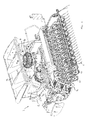
- Said tillage machine 1 can be designed as an attachment, which can be attached to a towing vehicle, for example in the form of a tractor, not shown, via a coupling device, for example, comprising a trestle 2 and a conventional three-point linkage.
- the seeder may comprise a seed and / or fertilizer tank 3 from which seed and / or fertilizer via a distribution system 4 to a plurality of Ausbringierin 5 can be guided, which can be arranged distributed transversely to the direction of travel across the machine width.
- Said distribution system 4 may comprise a pneumatically operated distributor head 6 from which the seed or fertilizer is fed to the respective application elements via seed and / or fertilizer lines 7.
- the distribution system 4 may comprise a grain separating device 8 by means of which grains can be dispensed individually at a defined distance from each other.
- Grains such as, for example, maize seed grains
- the grain separating device could in principle be provided at the bottom of the sowing coulter in order to have more space, but it may also be arranged at the top in the region of the seedling, as this Fig. 1 shows.
- the machine may have both said granule singulation and a distributor device for drill seed, since the machine is advantageously switchable between the two operating modes, as will be explained.
- seed drilling the seed is essentially spread over all dispensing elements over the entire width of the machine, while only a few of the seed coulters are used for single-seed placement.
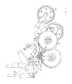
- the tillage assembly comprises two rows of share tools 9, each of which may comprise a rotatably mounted coulter disk whose axis of rotation - roughly speaking - can be arranged lying transversely to the direction of travel.
- the downpipes of the seed or fertilizer lines can end, so that the seed can be deposited in the furrow pulled by the respective coulter disc.
- Downstream of the coulter tools 9 can be provided pressure rollers 10, by means of which the seed is pressed down on the ground.
- Suppliers 11 can run after the said pinch rollers 10.
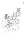
- the aforementioned sharpening tools 9 can advantageously be suspended elastically yielding by means of arm support arms 12, so that they can perform at least limited up and down movements, for example in order to avoid stones or to follow wavy ground contours better.
- said coulter arms 17 may, on the one hand, carry the aforementioned coulter tools 9 and, on the other hand, be articulated to a frame support member 13, from which said coulter arms 12 - roughly speaking - can extend obliquely backwards / downwards inclined to the horizontal.
- a coulter support arms 12 may carry a coulter tool 9 or a pair of such coulter tools 9, for example in the form of a double-disc arrangement.
- the frame support members 13 on which the coulter support arms 12 are mounted may be in the form of elongated profile pieces, which may extend lying transversely to the direction of travel, for the share tools a row a common, continuous, extending over the machine width frame support member 13 or a may be provided from several pieces existing frame support member.
- the coulter support arms 12 are articulated to said frame support member 13 advantageously by means of a resilient Quetsch instituteelagerung, wherein the coulter arm may have a roughly sleeve-shaped bearing head, which surrounds the said frame member, so that the frame member longitudinal axis forms a pivot axis for the Schartragarme 12 , Said frame support member 13 and this encompassing bearing head of Schartragarme here have a deviating from the circular contour or a deviating from the circular profile cross-section, so that between the sleeve-shaped bearing head and the Frame support member 13 form slit-shaped receiving pockets for elastic Quetschlageremia, for example in the form of roughly cylindrical or otherwise contoured Gummiquetschierin that deform during pivoting of the Schartragarme 12 and thereby generate corresponding restoring forces.
- the coulter arms 12 can hereby be mounted individually or in pairs or in other subgroups on the said frame support part 13.
- the said elastic rubber mounting is basically provided for all Schartragarme 12.
- selected share arms 12 can be additionally acted upon by force transmitters to control the coulter pressure on the corresponding share tools, in particular to increase.
- the Schartragarme 12 can be acted upon with an increased coulter pressure, which are provided for the Einzelkornablage, since with Einzelkornablage a higher coulter pressure is advantageous than is the case with Drillsaat.
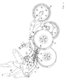
- the coulter pressure adjustment device associated with this subgroup of the coulter tools 9 comprises, in particular, biasing devices 14 for urging the respective coulter support arms 12 with an additional biasing force on the ground in order to correspondingly increase the coulter pressure.
- the aforementioned biasing devices 14 may in this case be formed as spring means 15, which may be formed, for example, in the form of mechanical springs, here depending on the arrangement of the spring means 15 tension or compression springs can equally be used.
- the named spring device 15 can be designed in particular in the form of mechanical springs.
- the said spring means 15 may be articulated on the one hand with a pivot point 16 on the respective Schartragarm 12 and an associated pivot piece and on the other hand be articulated with a pivot point 17 on a frame side coupling part 18, which hinged part 18 supported on the frame member part 13 and thereto can be stored or attached.
- the pivot points 16 and 17 are chosen such that the exerted by the spring means 15 spring force the respective Schartragarm 12 tries to pivot such that the attached blade tool 9 is pressed more strongly against the ground.
- the spring force which can be exerted by the spring device 15 is switchable and can be switched away and advantageously also adjusted in height when it is switched on.
- the corresponding access / disconnect means for activating and / or deactivating the pretensioning device 14 can, in a simple embodiment, provide a release and / or displacement of one of the abovementioned articulation points 16 and 17.
- the Tragarm workede articulation point 16 can be solved, for example by means of pull-out Anlenkbolzen.
- the spring means 15 can be fixed in a particular pivot hole by inserting a bolt or just solved by pulling the bolt, the spring means 15 can then be guided, for example, in a slot slidably.
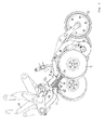
- an adjustment of the spring force can also be effected by an adjusting device 19, by means of which, for example, the other articulation point 17 can be adjusted in its position.
- the coupling part 18, on which the articulation point 17 of the spring device 15 is provided may be designed in the manner of a pivoting lever, which can be rotatably mounted about the axis of the frame support part 13, so that the articulation point 17 in the direction of the axis of action - at least one Movement component - moves and thereby the spring force can be adjusted.
- Said pivoting lever 18 is part of the adjusting device 19 and can be externally energized, for example via an operating link and / or a Stellaktor or manually pivoted.
- the adjustability or mobility of said coupling member 18 can also be used to allow a jam-free or low-force release and insertion of the bolt at the opposite pivot point 16. If the spring device 15 is relaxed by appropriate movement of the Anlenkteils 18, as for example in Fig. 5 is shown, the Anlenkbolzen at the pivot point 16 easily solve or easily plug in again.
Landscapes
- Life Sciences & Earth Sciences (AREA)
- Soil Sciences (AREA)
- Environmental Sciences (AREA)
- Soil Working Implements (AREA)
Priority Applications (1)
| Application Number | Priority Date | Filing Date | Title |
|---|---|---|---|
| PL14196229T PL2912933T3 (pl) | 2014-02-28 | 2014-12-04 | Maszyna rolnicza do uprawy roli |
Applications Claiming Priority (1)
| Application Number | Priority Date | Filing Date | Title |
|---|---|---|---|
| DE102014002911.5A DE102014002911A1 (de) | 2014-02-28 | 2014-02-28 | Landwirtschaftliche Bodenbearbeitungsmaschine |
Publications (2)
| Publication Number | Publication Date |
|---|---|
| EP2912933A1 true EP2912933A1 (fr) | 2015-09-02 |
| EP2912933B1 EP2912933B1 (fr) | 2018-01-31 |
Family
ID=52013888
Family Applications (1)
| Application Number | Title | Priority Date | Filing Date |
|---|---|---|---|
| EP14196229.0A Active EP2912933B1 (fr) | 2014-02-28 | 2014-12-04 | Machine agricole de traitement du sol |
Country Status (3)
| Country | Link |
|---|---|
| EP (1) | EP2912933B1 (fr) |
| DE (1) | DE102014002911A1 (fr) |
| PL (1) | PL2912933T3 (fr) |
Cited By (4)
| Publication number | Priority date | Publication date | Assignee | Title |
|---|---|---|---|---|
| DE102015109507A1 (de) * | 2015-06-15 | 2016-12-15 | Thomas Kraus | Pflanzmaschine zum Pflanzen von Blumenzwiebeln beim Anlegen von Blumenfeldern |
| EP3266293A1 (fr) * | 2016-07-07 | 2018-01-10 | Amazonen-Werke H. Dreyer GmbH & Co. KG | Semoir agricole comprenant un dispositif de recouvrement et/ou de pression |
| EP3266294A1 (fr) * | 2016-07-04 | 2018-01-10 | Amazonen-Werke H. Dreyer GmbH & Co. KG | Semoir agricole comprenant un dispositif de recouvrement et/ou de pression |
| EP3364740A1 (fr) * | 2015-10-20 | 2018-08-29 | Matermacc S.p.A. | Groupe distributeur d'engrais |
Families Citing this family (4)
| Publication number | Priority date | Publication date | Assignee | Title |
|---|---|---|---|---|
| DE202019100923U1 (de) | 2019-02-19 | 2020-05-20 | Pöttinger Landtechnik Gmbh | Vorrichtung für eine landwirtschaftliche Maschine |
| DE102020113479A1 (de) | 2020-05-19 | 2021-11-25 | Amazonen-Werke H. Dreyer SE & Co. KG | Sävorrichtung und landwirtschaftliche Sä- und/oder Düngermaschine |
| DE102023108193A1 (de) | 2023-03-30 | 2024-10-02 | Lemken Gmbh & Co. Kg | Ausbringmaschine |
| DE102024130076A1 (de) * | 2024-10-16 | 2026-04-16 | Amazonen-Werke H. Dreyer SE & Co. KG | Landwirtschaftliche Sämaschine und Verfahren zum Betreiben einer landwirtschaftlichen Sämaschine |
Citations (7)
| Publication number | Priority date | Publication date | Assignee | Title |
|---|---|---|---|---|
| US4977841A (en) * | 1989-12-01 | 1990-12-18 | Truax James R | Torsional joint attachment for a seed planter |
| DE4108210A1 (de) * | 1991-03-14 | 1992-09-17 | Fritz Guettler | Hindernissen im boden allseitig ausweichende und von selbst auf den eingestellten reihenabstand sich einsteuernde und zentrierende saeschare |
| DE29910414U1 (de) * | 1999-06-15 | 1999-08-26 | Horsch Maschinen GmbH, 92421 Schwandorf | Säscharanordnung |
| DE102004043565A1 (de) * | 2004-09-09 | 2006-03-30 | Amazonen-Werke H. Dreyer Gmbh & Co. Kg | Sämaschine |
| DE102007010626A1 (de) * | 2007-03-02 | 2008-09-04 | Rauch Landmaschinenfabrik Gmbh | Sämaschine |
| DE102007053001B3 (de) * | 2007-11-05 | 2009-04-02 | Kverneland Asa | Saatgut- und/oder Düngerverteilmaschine |
| EP1911340B1 (fr) * | 2006-10-14 | 2010-05-12 | Lemken GmbH & Co. KG | Soc à double disque doté d'un rouleau de guidage en profondeur et mécanisme de pivotement |
Family Cites Families (3)
| Publication number | Priority date | Publication date | Assignee | Title |
|---|---|---|---|---|
| DE102006011197A1 (de) * | 2006-03-10 | 2007-09-13 | Rabe Agri Gmbh | Sämaschine |
| DE202007006919U1 (de) * | 2007-05-14 | 2008-09-25 | Alois Pöttinger Maschinenfabrik Gmbh | Bodenbearbeitungsmaschine |
| US8985234B2 (en) * | 2011-11-15 | 2015-03-24 | Cnh Industrial Canada, Ltd. | System for applying down pressure in a coulter assembly |
-
2014
- 2014-02-28 DE DE102014002911.5A patent/DE102014002911A1/de active Pending
- 2014-12-04 PL PL14196229T patent/PL2912933T3/pl unknown
- 2014-12-04 EP EP14196229.0A patent/EP2912933B1/fr active Active
Patent Citations (7)
| Publication number | Priority date | Publication date | Assignee | Title |
|---|---|---|---|---|
| US4977841A (en) * | 1989-12-01 | 1990-12-18 | Truax James R | Torsional joint attachment for a seed planter |
| DE4108210A1 (de) * | 1991-03-14 | 1992-09-17 | Fritz Guettler | Hindernissen im boden allseitig ausweichende und von selbst auf den eingestellten reihenabstand sich einsteuernde und zentrierende saeschare |
| DE29910414U1 (de) * | 1999-06-15 | 1999-08-26 | Horsch Maschinen GmbH, 92421 Schwandorf | Säscharanordnung |
| DE102004043565A1 (de) * | 2004-09-09 | 2006-03-30 | Amazonen-Werke H. Dreyer Gmbh & Co. Kg | Sämaschine |
| EP1911340B1 (fr) * | 2006-10-14 | 2010-05-12 | Lemken GmbH & Co. KG | Soc à double disque doté d'un rouleau de guidage en profondeur et mécanisme de pivotement |
| DE102007010626A1 (de) * | 2007-03-02 | 2008-09-04 | Rauch Landmaschinenfabrik Gmbh | Sämaschine |
| DE102007053001B3 (de) * | 2007-11-05 | 2009-04-02 | Kverneland Asa | Saatgut- und/oder Düngerverteilmaschine |
Cited By (5)
| Publication number | Priority date | Publication date | Assignee | Title |
|---|---|---|---|---|
| DE102015109507A1 (de) * | 2015-06-15 | 2016-12-15 | Thomas Kraus | Pflanzmaschine zum Pflanzen von Blumenzwiebeln beim Anlegen von Blumenfeldern |
| EP3364740A1 (fr) * | 2015-10-20 | 2018-08-29 | Matermacc S.p.A. | Groupe distributeur d'engrais |
| US10470359B2 (en) | 2015-10-20 | 2019-11-12 | Matermacc S.P.A. | Fertilizer distributor group |
| EP3266294A1 (fr) * | 2016-07-04 | 2018-01-10 | Amazonen-Werke H. Dreyer GmbH & Co. KG | Semoir agricole comprenant un dispositif de recouvrement et/ou de pression |
| EP3266293A1 (fr) * | 2016-07-07 | 2018-01-10 | Amazonen-Werke H. Dreyer GmbH & Co. KG | Semoir agricole comprenant un dispositif de recouvrement et/ou de pression |
Also Published As
| Publication number | Publication date |
|---|---|
| DE102014002911A1 (de) | 2015-09-03 |
| EP2912933B1 (fr) | 2018-01-31 |
| PL2912933T3 (pl) | 2018-07-31 |
Similar Documents
| Publication | Publication Date | Title |
|---|---|---|
| EP2912933B1 (fr) | Machine agricole de traitement du sol | |
| DE60037458T2 (de) | Landwirtschaftliches Gerät | |
| DE2552810A1 (de) | Maschine zum ausbringen von saatgut und duengemitteln | |
| DE102007052353A1 (de) | Sä- und/oder Bodenbearbeitungsmaschine | |
| EP1974596B1 (fr) | Ensemble de soc semeur | |
| EP3545737B1 (fr) | Appareil de traitement du sol pourvu d'au moins une unité de rouleau d'étrillage | |
| EP3556192A1 (fr) | Machine agricole de traitement du sol ainsi que procédé de traitement du sol | |
| DE102004023087A1 (de) | Drillmaschine | |
| EP0796553A2 (fr) | Semoir, en particulier pour semis en paillage | |
| DE2741373A1 (de) | Bodenbearbeitungsmaschine | |
| EP3357317B1 (fr) | Assemblage du soc pour un semoir | |
| DE19644751A1 (de) | Drillmaschine mit Stellvorrichtung für Säschar und Druckrolle | |
| EP1647174A1 (fr) | Appareil agricole | |
| DE202019100926U1 (de) | Vorrichtung für eine landwirtschaftliche Maschine | |
| DE102007011297B4 (de) | Gezogene Säscharanordnung | |
| EP0445582B1 (fr) | Machine pour travailler le sol | |
| EP3808163A1 (fr) | Scarificateur agricole | |
| EP3127412A1 (fr) | Machine agricole destinee a traiter le sol et a extraire les semences | |
| DE602004004342T2 (de) | Sämaschine mit einer Einstellvorrichtung | |
| EP3266293A1 (fr) | Semoir agricole comprenant un dispositif de recouvrement et/ou de pression | |
| EP0858258B1 (fr) | Machine a semer en ligne pourvue d'un dispositif de reglage du coutre d'ensemencement et du rouleau de pression | |
| DE3033144C2 (de) | Schleppergezogene Bodenbearbeitungs- und Sämaschine | |
| EP4316231A1 (fr) | Dispositif de soc et machine de travail agricole dotée d'une pluralité de tels dispositifs de soc | |
| EP3698617B1 (fr) | Système de soc de semis pour une machine agricole | |
| WO2019030309A1 (fr) | Soc de semoir et semoir |
Legal Events
| Date | Code | Title | Description |
|---|---|---|---|
| PUAI | Public reference made under article 153(3) epc to a published international application that has entered the european phase |
Free format text: ORIGINAL CODE: 0009012 |
|
| AK | Designated contracting states |
Kind code of ref document: A1 Designated state(s): AL AT BE BG CH CY CZ DE DK EE ES FI FR GB GR HR HU IE IS IT LI LT LU LV MC MK MT NL NO PL PT RO RS SE SI SK SM TR |
|
| AX | Request for extension of the european patent |
Extension state: BA ME |
|
| 17P | Request for examination filed |
Effective date: 20160215 |
|
| RAP1 | Party data changed (applicant data changed or rights of an application transferred) |
Owner name: POETTINGER LANDTECHNIK GMBH |
|
| RIC1 | Information provided on ipc code assigned before grant |
Ipc: A01C 7/08 20060101ALN20170523BHEP Ipc: A01C 7/20 20060101AFI20170523BHEP Ipc: A01C 7/04 20060101ALN20170523BHEP |
|
| GRAP | Despatch of communication of intention to grant a patent |
Free format text: ORIGINAL CODE: EPIDOSNIGR1 |
|
| RIC1 | Information provided on ipc code assigned before grant |
Ipc: A01C 7/20 20060101AFI20170529BHEP Ipc: A01C 7/04 20060101ALN20170529BHEP Ipc: A01C 7/08 20060101ALN20170529BHEP |
|
| INTG | Intention to grant announced |
Effective date: 20170704 |
|
| GRAS | Grant fee paid |
Free format text: ORIGINAL CODE: EPIDOSNIGR3 |
|
| GRAA | (expected) grant |
Free format text: ORIGINAL CODE: 0009210 |
|
| AK | Designated contracting states |
Kind code of ref document: B1 Designated state(s): AL AT BE BG CH CY CZ DE DK EE ES FI FR GB GR HR HU IE IS IT LI LT LU LV MC MK MT NL NO PL PT RO RS SE SI SK SM TR |
|
| REG | Reference to a national code |
Ref country code: GB Ref legal event code: FG4D Free format text: NOT ENGLISH Ref country code: CH Ref legal event code: EP |
|
| REG | Reference to a national code |
Ref country code: AT Ref legal event code: REF Ref document number: 966482 Country of ref document: AT Kind code of ref document: T Effective date: 20180215 |
|
| REG | Reference to a national code |
Ref country code: IE Ref legal event code: FG4D Free format text: LANGUAGE OF EP DOCUMENT: GERMAN |
|
| REG | Reference to a national code |
Ref country code: DE Ref legal event code: R096 Ref document number: 502014007100 Country of ref document: DE |
|
| REG | Reference to a national code |
Ref country code: SE Ref legal event code: TRGR |
|
| REG | Reference to a national code |
Ref country code: NL Ref legal event code: MP Effective date: 20180131 |
|
| REG | Reference to a national code |
Ref country code: LT Ref legal event code: MG4D |
|
| PG25 | Lapsed in a contracting state [announced via postgrant information from national office to epo] |
Ref country code: FI Free format text: LAPSE BECAUSE OF FAILURE TO SUBMIT A TRANSLATION OF THE DESCRIPTION OR TO PAY THE FEE WITHIN THE PRESCRIBED TIME-LIMIT Effective date: 20180131 Ref country code: NL Free format text: LAPSE BECAUSE OF FAILURE TO SUBMIT A TRANSLATION OF THE DESCRIPTION OR TO PAY THE FEE WITHIN THE PRESCRIBED TIME-LIMIT Effective date: 20180131 Ref country code: HR Free format text: LAPSE BECAUSE OF FAILURE TO SUBMIT A TRANSLATION OF THE DESCRIPTION OR TO PAY THE FEE WITHIN THE PRESCRIBED TIME-LIMIT Effective date: 20180131 Ref country code: NO Free format text: LAPSE BECAUSE OF FAILURE TO SUBMIT A TRANSLATION OF THE DESCRIPTION OR TO PAY THE FEE WITHIN THE PRESCRIBED TIME-LIMIT Effective date: 20180430 Ref country code: LT Free format text: LAPSE BECAUSE OF FAILURE TO SUBMIT A TRANSLATION OF THE DESCRIPTION OR TO PAY THE FEE WITHIN THE PRESCRIBED TIME-LIMIT Effective date: 20180131 Ref country code: ES Free format text: LAPSE BECAUSE OF FAILURE TO SUBMIT A TRANSLATION OF THE DESCRIPTION OR TO PAY THE FEE WITHIN THE PRESCRIBED TIME-LIMIT Effective date: 20180131 |
|
| PG25 | Lapsed in a contracting state [announced via postgrant information from national office to epo] |
Ref country code: IS Free format text: LAPSE BECAUSE OF FAILURE TO SUBMIT A TRANSLATION OF THE DESCRIPTION OR TO PAY THE FEE WITHIN THE PRESCRIBED TIME-LIMIT Effective date: 20180531 Ref country code: RS Free format text: LAPSE BECAUSE OF FAILURE TO SUBMIT A TRANSLATION OF THE DESCRIPTION OR TO PAY THE FEE WITHIN THE PRESCRIBED TIME-LIMIT Effective date: 20180131 Ref country code: BG Free format text: LAPSE BECAUSE OF FAILURE TO SUBMIT A TRANSLATION OF THE DESCRIPTION OR TO PAY THE FEE WITHIN THE PRESCRIBED TIME-LIMIT Effective date: 20180430 Ref country code: LV Free format text: LAPSE BECAUSE OF FAILURE TO SUBMIT A TRANSLATION OF THE DESCRIPTION OR TO PAY THE FEE WITHIN THE PRESCRIBED TIME-LIMIT Effective date: 20180131 Ref country code: GR Free format text: LAPSE BECAUSE OF FAILURE TO SUBMIT A TRANSLATION OF THE DESCRIPTION OR TO PAY THE FEE WITHIN THE PRESCRIBED TIME-LIMIT Effective date: 20180501 |
|
| PG25 | Lapsed in a contracting state [announced via postgrant information from national office to epo] |
Ref country code: MT Free format text: LAPSE BECAUSE OF FAILURE TO SUBMIT A TRANSLATION OF THE DESCRIPTION OR TO PAY THE FEE WITHIN THE PRESCRIBED TIME-LIMIT Effective date: 20180131 |
|
| PG25 | Lapsed in a contracting state [announced via postgrant information from national office to epo] |
Ref country code: EE Free format text: LAPSE BECAUSE OF FAILURE TO SUBMIT A TRANSLATION OF THE DESCRIPTION OR TO PAY THE FEE WITHIN THE PRESCRIBED TIME-LIMIT Effective date: 20180131 Ref country code: RO Free format text: LAPSE BECAUSE OF FAILURE TO SUBMIT A TRANSLATION OF THE DESCRIPTION OR TO PAY THE FEE WITHIN THE PRESCRIBED TIME-LIMIT Effective date: 20180131 Ref country code: AL Free format text: LAPSE BECAUSE OF FAILURE TO SUBMIT A TRANSLATION OF THE DESCRIPTION OR TO PAY THE FEE WITHIN THE PRESCRIBED TIME-LIMIT Effective date: 20180131 |
|
| REG | Reference to a national code |
Ref country code: DE Ref legal event code: R097 Ref document number: 502014007100 Country of ref document: DE |
|
| PG25 | Lapsed in a contracting state [announced via postgrant information from national office to epo] |
Ref country code: SK Free format text: LAPSE BECAUSE OF FAILURE TO SUBMIT A TRANSLATION OF THE DESCRIPTION OR TO PAY THE FEE WITHIN THE PRESCRIBED TIME-LIMIT Effective date: 20180131 Ref country code: SM Free format text: LAPSE BECAUSE OF FAILURE TO SUBMIT A TRANSLATION OF THE DESCRIPTION OR TO PAY THE FEE WITHIN THE PRESCRIBED TIME-LIMIT Effective date: 20180131 Ref country code: DK Free format text: LAPSE BECAUSE OF FAILURE TO SUBMIT A TRANSLATION OF THE DESCRIPTION OR TO PAY THE FEE WITHIN THE PRESCRIBED TIME-LIMIT Effective date: 20180131 |
|
| PLBE | No opposition filed within time limit |
Free format text: ORIGINAL CODE: 0009261 |
|
| STAA | Information on the status of an ep patent application or granted ep patent |
Free format text: STATUS: NO OPPOSITION FILED WITHIN TIME LIMIT |
|
| 26N | No opposition filed |
Effective date: 20181102 |
|
| PG25 | Lapsed in a contracting state [announced via postgrant information from national office to epo] |
Ref country code: SI Free format text: LAPSE BECAUSE OF FAILURE TO SUBMIT A TRANSLATION OF THE DESCRIPTION OR TO PAY THE FEE WITHIN THE PRESCRIBED TIME-LIMIT Effective date: 20180131 |
|
| PGFP | Annual fee paid to national office [announced via postgrant information from national office to epo] |
Ref country code: PL Payment date: 20181113 Year of fee payment: 5 |
|
| REG | Reference to a national code |
Ref country code: CH Ref legal event code: PL |
|
| GBPC | Gb: european patent ceased through non-payment of renewal fee |
Effective date: 20181204 |
|
| PG25 | Lapsed in a contracting state [announced via postgrant information from national office to epo] |
Ref country code: MC Free format text: LAPSE BECAUSE OF FAILURE TO SUBMIT A TRANSLATION OF THE DESCRIPTION OR TO PAY THE FEE WITHIN THE PRESCRIBED TIME-LIMIT Effective date: 20180131 Ref country code: LU Free format text: LAPSE BECAUSE OF NON-PAYMENT OF DUE FEES Effective date: 20181204 |
|
| REG | Reference to a national code |
Ref country code: IE Ref legal event code: MM4A |
|
| REG | Reference to a national code |
Ref country code: BE Ref legal event code: MM Effective date: 20181231 |
|
| PG25 | Lapsed in a contracting state [announced via postgrant information from national office to epo] |
Ref country code: IE Free format text: LAPSE BECAUSE OF NON-PAYMENT OF DUE FEES Effective date: 20181204 |
|
| PG25 | Lapsed in a contracting state [announced via postgrant information from national office to epo] |
Ref country code: BE Free format text: LAPSE BECAUSE OF NON-PAYMENT OF DUE FEES Effective date: 20181231 |
|
| PG25 | Lapsed in a contracting state [announced via postgrant information from national office to epo] |
Ref country code: GB Free format text: LAPSE BECAUSE OF NON-PAYMENT OF DUE FEES Effective date: 20181204 Ref country code: LI Free format text: LAPSE BECAUSE OF NON-PAYMENT OF DUE FEES Effective date: 20181231 Ref country code: CH Free format text: LAPSE BECAUSE OF NON-PAYMENT OF DUE FEES Effective date: 20181231 |
|
| PG25 | Lapsed in a contracting state [announced via postgrant information from national office to epo] |
Ref country code: TR Free format text: LAPSE BECAUSE OF FAILURE TO SUBMIT A TRANSLATION OF THE DESCRIPTION OR TO PAY THE FEE WITHIN THE PRESCRIBED TIME-LIMIT Effective date: 20180131 |
|
| PGFP | Annual fee paid to national office [announced via postgrant information from national office to epo] |
Ref country code: AT Payment date: 20191127 Year of fee payment: 6 |
|
| PG25 | Lapsed in a contracting state [announced via postgrant information from national office to epo] |
Ref country code: PT Free format text: LAPSE BECAUSE OF FAILURE TO SUBMIT A TRANSLATION OF THE DESCRIPTION OR TO PAY THE FEE WITHIN THE PRESCRIBED TIME-LIMIT Effective date: 20180131 |
|
| PG25 | Lapsed in a contracting state [announced via postgrant information from national office to epo] |
Ref country code: MK Free format text: LAPSE BECAUSE OF NON-PAYMENT OF DUE FEES Effective date: 20180131 Ref country code: HU Free format text: LAPSE BECAUSE OF FAILURE TO SUBMIT A TRANSLATION OF THE DESCRIPTION OR TO PAY THE FEE WITHIN THE PRESCRIBED TIME-LIMIT; INVALID AB INITIO Effective date: 20141204 Ref country code: CY Free format text: LAPSE BECAUSE OF FAILURE TO SUBMIT A TRANSLATION OF THE DESCRIPTION OR TO PAY THE FEE WITHIN THE PRESCRIBED TIME-LIMIT Effective date: 20180131 |
|
| REG | Reference to a national code |
Ref country code: AT Ref legal event code: MM01 Ref document number: 966482 Country of ref document: AT Kind code of ref document: T Effective date: 20201204 |
|
| PG25 | Lapsed in a contracting state [announced via postgrant information from national office to epo] |
Ref country code: AT Free format text: LAPSE BECAUSE OF NON-PAYMENT OF DUE FEES Effective date: 20201204 |
|
| PG25 | Lapsed in a contracting state [announced via postgrant information from national office to epo] |
Ref country code: PL Free format text: LAPSE BECAUSE OF NON-PAYMENT OF DUE FEES Effective date: 20191204 |
|
| P01 | Opt-out of the competence of the unified patent court (upc) registered |
Effective date: 20230613 |
|
| PGFP | Annual fee paid to national office [announced via postgrant information from national office to epo] |
Ref country code: DE Payment date: 20251216 Year of fee payment: 12 |
|
| PGFP | Annual fee paid to national office [announced via postgrant information from national office to epo] |
Ref country code: FR Payment date: 20251229 Year of fee payment: 12 |
|
| PGFP | Annual fee paid to national office [announced via postgrant information from national office to epo] |
Ref country code: SE Payment date: 20251229 Year of fee payment: 12 |
|
| PGFP | Annual fee paid to national office [announced via postgrant information from national office to epo] |
Ref country code: CZ Payment date: 20251119 Year of fee payment: 12 |
|
| PGFP | Annual fee paid to national office [announced via postgrant information from national office to epo] |
Ref country code: IT Payment date: 20251217 Year of fee payment: 12 |