EP2913109A1 - Ensemble thermocycleur pour PCR - Google Patents
Ensemble thermocycleur pour PCR Download PDFInfo
- Publication number
- EP2913109A1 EP2913109A1 EP14198058.1A EP14198058A EP2913109A1 EP 2913109 A1 EP2913109 A1 EP 2913109A1 EP 14198058 A EP14198058 A EP 14198058A EP 2913109 A1 EP2913109 A1 EP 2913109A1
- Authority
- EP
- European Patent Office
- Prior art keywords
- sample
- vials
- temperature
- assembly
- thermal
- Prior art date
- Legal status (The legal status is an assumption and is not a legal conclusion. Google has not performed a legal analysis and makes no representation as to the accuracy of the status listed.)
- Withdrawn
Links
Images


Classifications
-
- B—PERFORMING OPERATIONS; TRANSPORTING
- B01—PHYSICAL OR CHEMICAL PROCESSES OR APPARATUS IN GENERAL
- B01L—CHEMICAL OR PHYSICAL LABORATORY APPARATUS FOR GENERAL USE
- B01L7/00—Heating or cooling apparatus; Heat insulating devices
- B01L7/52—Heating or cooling apparatus; Heat insulating devices with provision for submitting samples to a predetermined sequence of different temperatures, e.g. for treating nucleic acid samples
-
- B—PERFORMING OPERATIONS; TRANSPORTING
- B01—PHYSICAL OR CHEMICAL PROCESSES OR APPARATUS IN GENERAL
- B01L—CHEMICAL OR PHYSICAL LABORATORY APPARATUS FOR GENERAL USE
- B01L3/00—Containers or dishes for laboratory use, e.g. laboratory glassware; Droppers
- B01L3/50—Containers for the purpose of retaining a material to be analysed, e.g. test tubes
- B01L3/508—Rigid containers without fluid transport within
- B01L3/5085—Rigid containers without fluid transport within for multiple samples, e.g. microtitration plates
- B01L3/50853—Rigid containers without fluid transport within for multiple samples, e.g. microtitration plates with covers or lids
-
- G—PHYSICS
- G01—MEASURING; TESTING
- G01R—MEASURING ELECTRIC VARIABLES; MEASURING MAGNETIC VARIABLES
- G01R27/00—Arrangements for measuring resistance, reactance, impedance, or electric characteristics derived therefrom
- G01R27/02—Measuring real or complex resistance, reactance, impedance, or other two-pole characteristics derived therefrom, e.g. time constant
- G01R27/20—Measuring earth resistance; Measuring contact resistance, e.g. of earth connections, e.g. plates
- G01R27/205—Measuring contact resistance of connections, e.g. of earth connections
-
- G—PHYSICS
- G05—CONTROLLING; REGULATING
- G05D—SYSTEMS FOR CONTROLLING OR REGULATING NON-ELECTRIC VARIABLES
- G05D23/00—Control of temperature
- G05D23/19—Control of temperature characterised by the use of electric means
- G05D23/1919—Control of temperature characterised by the use of electric means characterised by the type of controller
-
- H—ELECTRICITY
- H10—SEMICONDUCTOR DEVICES; ELECTRIC SOLID-STATE DEVICES NOT OTHERWISE PROVIDED FOR
- H10N—ELECTRIC SOLID-STATE DEVICES NOT OTHERWISE PROVIDED FOR
- H10N10/00—Thermoelectric devices comprising a junction of dissimilar materials, i.e. devices exhibiting Seebeck or Peltier effects
- H10N10/10—Thermoelectric devices comprising a junction of dissimilar materials, i.e. devices exhibiting Seebeck or Peltier effects operating with only the Peltier or Seebeck effects
- H10N10/13—Thermoelectric devices comprising a junction of dissimilar materials, i.e. devices exhibiting Seebeck or Peltier effects operating with only the Peltier or Seebeck effects characterised by the heat-exchanging means at the junction
-
- B—PERFORMING OPERATIONS; TRANSPORTING
- B01—PHYSICAL OR CHEMICAL PROCESSES OR APPARATUS IN GENERAL
- B01L—CHEMICAL OR PHYSICAL LABORATORY APPARATUS FOR GENERAL USE
- B01L2300/00—Additional constructional details
- B01L2300/04—Closures and closing means
- B01L2300/041—Connecting closures to device or container
- B01L2300/045—Connecting closures to device or container whereby the whole cover is slidable
-
- B—PERFORMING OPERATIONS; TRANSPORTING
- B01—PHYSICAL OR CHEMICAL PROCESSES OR APPARATUS IN GENERAL
- B01L—CHEMICAL OR PHYSICAL LABORATORY APPARATUS FOR GENERAL USE
- B01L2300/00—Additional constructional details
- B01L2300/08—Geometry, shape and general structure
- B01L2300/0809—Geometry, shape and general structure rectangular shaped
- B01L2300/0829—Multi-well plates; Microtitration plates
-
- B—PERFORMING OPERATIONS; TRANSPORTING
- B01—PHYSICAL OR CHEMICAL PROCESSES OR APPARATUS IN GENERAL
- B01L—CHEMICAL OR PHYSICAL LABORATORY APPARATUS FOR GENERAL USE
- B01L2300/00—Additional constructional details
- B01L2300/18—Means for temperature control
- B01L2300/1805—Conductive heating, heat from thermostatted solids is conducted to receptacles, e.g. heating plates, blocks
- B01L2300/1822—Conductive heating, heat from thermostatted solids is conducted to receptacles, e.g. heating plates, blocks using Peltier elements
-
- B—PERFORMING OPERATIONS; TRANSPORTING
- B01—PHYSICAL OR CHEMICAL PROCESSES OR APPARATUS IN GENERAL
- B01L—CHEMICAL OR PHYSICAL LABORATORY APPARATUS FOR GENERAL USE
- B01L2300/00—Additional constructional details
- B01L2300/18—Means for temperature control
- B01L2300/1805—Conductive heating, heat from thermostatted solids is conducted to receptacles, e.g. heating plates, blocks
- B01L2300/1827—Conductive heating, heat from thermostatted solids is conducted to receptacles, e.g. heating plates, blocks using resistive heater
Definitions
- This invention pertains to the field of computer controlled instruments for performing the Polymerase Chain Reaction (PCR). More particularly, the invention pertains to automated instruments that perform the reaction simultaneously on many samples and produce very precise results by using thermal cycling.
- PCR Polymerase Chain Reaction
- the chemical reaction has an optimum temperature for each of its stages. Thus, less time spent at non optimum temperature means a better chemical result is achieved. Also a minimum time for holding the reaction mixture at each incubation temperature is required after each said incubation temperature is reached. These minimum incubation times establish the minimum time it takes to complete a cycle. Any time in transition between sample incubation temperatures is time added to this minimum cycle time. Since the number of cycles is fairly large, this additional time unnecessarily heightens the total time needed to complete the amplification.
- an apparatus for performing the Polymerase Chain Reaction comprising an assembly capable of cycling samples through a series of temperature excursions, a heated cover and a computer to control the process.
- the invention further encompasses a sample block with low thermal mass for rapid temperature excursions.
- the sample block is preferably manufactured from silver for uniform overall heat distribution and has a bottom plate for uniform lateral heat distribution.
- a center pin is used as a conducting path to a heat sink.
- the invention is also directed to a clamping mechanism to hold the sample block to the heat sink with the thermoelectric devices positioned in between.
- the mechanism is designed to provide evenly distributed pressure with a minimal heat load.
- the design allows the use of thermal grease as an interface between the sample block, and the thermoelectric devices and between the thermoelectric devices and the heatsink.
- a heated cover designed to keep the sample tubes closed during cycling and to heat the upper portion of the tubes to prevent condensation.
- the heated cover applies pressure on the sample tube cap perimeter to avoid distorting the cap's optical qualities.
- the cover is self-aligning, using a skirt which mates with a sample tube tray.
- the invention is also directed to a method and apparatus for determining an ideal temperature ramp rate which is determined so as to take advantage of sample block temperature overshoots and undershoots in order to minimize cycle time.
- the invention also includes a method and apparatus for characterizing the thermal power output from the thermal electric cooling devices to achieve linear temperature control and linear and non-linear temperature ramps.
- the invention also includes a method and apparatus for utilizing calibration diagnostics which compensate for variations in the performance of the thermoelectric devices so that all instruments perform identically.
- the thermal characteristics and performance of the assembly comprised of the sample block, thermal electric devices and heatsink, is stored in an on-board memory device, allowing the assembly to be moved to another instrument and behave the same way.
- the invention further includes a method and apparatus for measuring the AC resistance of the thermoelectric devices to provide early indications of device failures.
- PCR it is desirable to change the sample temperature between the required temperatures in the cycle as quickly as possible for several reasons.
- the chemical reaction has an optimum temperature for each of it's stages and as such less time spent at non-optimum temperatures means a better chemical result is achieved.
- a minimum time is usually required at any given set point which sets a minimum cycle time for each protocol and any time spent in transition between set points adds to this minimum time. Since the number of cycles is usually quite large, this transition time can significantly add to the total time needed to complete the amplification.
- the absolute temperature that each reaction tube attains during each step of the protocol is critical to the yield of product. As the products are frequently subjected to quantitation, the product yield from tube to tube must be as uniform as possible and therefore both the steady-state and dynamic thermal uniformity must be excellent across the block.
- the amount of heat-pumping required is dependent on the thermal load and the ramp rate, that is, the rate at which the temperature is required to change.
- the sample tube geometry and sample volumes are not variables as the sample tubes are established as an industry standard, fitting into many other types of instruments such as centrifuges.
- the sample volume is defined by user need. Therefore the design variables primarily affect the sample block, thermoelectric devices, heatsink, fan and the thermal interface media between the thermoelectric devices and both the heatsink and the sample block.
- the block geometry must also meet the necessary thermal uniformity requirements because it is the primary contributor to lateral conduction and therefore evens out any variation in thermal uniformity of the thermoelectric coolers themselves.
- the conflicting requirements of rapid ramp rates (indicating low thermal mass) and high lateral conduction (indicating a large material mass) are met by concentrating the bulk of the block structure in a base plate, and minimizing the thermal mass of the upper portion of the block which holds the sample tubes.
- the optimal material for block fabrication is pure silver which has relatively low thermal mass and very good thermal conduction. Silver also lends itself well to electroforming. In practice the optimal block geometry has a light electroformed upper portion to hold the sample tubes fixed to a relatively thick base plate which provides lateral conduction.
- the thermal mass of the block is concentrated in the base plate where the material contributes the most to thermal uniformity.
- the electroformed portion of the block has a minimum thickness which is defined by two parameters: first, the material cannot be so thin as to make it too delicate for normal handling; second, the wall thickness is required to conduct heat out of the upper regions of the sample tube. Circulation in the sample itself is achieved by convection inside the tube and sample temperature is relatively uniform along the height of the tube, but good thermal conductivity between the tube walls and the base plate increases the effective surface area available for conduction of heat between the sample and the base plate.
- the base plate thickness has a minimum value defined by lateral conduction requirements which is a function of the thermal uniformity of the thermoelectric coolers and structural rigidity.
- the center temperature is reduced by providing a small thermal connection from the center of the sample block to the heat sink.
- a pin 24 which acts as a "heat leak" in the center of the sample block, the temperature gradient across the sample block can be reduced to an acceptable level.
- Figure 2 shows an isometric view of a typical Peltier thermal electric device.
- the alumina layer 26 that forms the outer wall of the thermal electric device, expands and contracts during temperature cycling at a different rate than the sample block 19.
- the motion of the alumina is transmitted directly to the solder 28 connecting the internal bismuth telluride pellets 30. This motion can be reduced dramatically by cutting the alumina into small pieces 32 called die so that the field of expansion is small.
- the minimum size of the die is defined by the size of the copper traces required to carry current through the thermal electric device and the requuirements thta the device retain some strength for handling.
- Using thin alumina layers in the thermal electric device (of the order of 0.508 mm) not only reduces the thermal load but also means that for a given required heat pumping rate the temperature that the ends of the pellet reaches is reduced due to the increase in thermal conductivity k. This enhances reliability by reducing the thermal stress on the solder joint.
- the heating ramp rate would be increased by increasing the height of the pellet. This is because the conduction path through the thermal electric device would be made longer thereby decreasing k. This also has the effect of reducing the current required to maintain a given block temperature in the steady state. During the down ramp, i.e. cooling the block, the decreased k means that the conduction contribution will be reduced and so the down ramp rate will be reduced.
- High temperature solder has been shown to not only have improved high temperature performance but it is also generally more resistant to failure by stress reversals and hence is most appropriate in this application.
- the solder used in this invention may be of the type as described in U.S. Patent 5,441,576 .
- the heatsink temperature uniformity is reflected in the uniformity of the block temperature. Typically the heatsink is warmer in the middle than it is at the edges and this adds to other effects that lead to the corners of the block being the coldest.
- a trench 44 is cut into the heat sink outside the perimeter of the thermal electric device area to limit the conduction of heat and decreases edge losses from the area bounded by the trench.
- the silver block is relatively flexible and soft it cannot transmit lateral clamping pressure very effectively.
- the thermal interface media is thermal grease, the clamping force required is low.
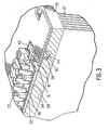
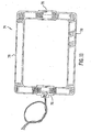
- FIG 4 shows an exploded view of the assembly with the preferred embodiment of the clamping mechanism.
- Each clamp 46 is made up of a series of fingers 48 extending from a spine 49.
- the fingers 48 are sized, shaped and spaced so as to fit between the wells 20 of the sample block 36 and thus apply pressure at a corresponding series of points on the base plate 22 of the sample block 36.
- the open honeycomb structure of the electroformed sample wells allows the fingers to be inserted some distance into the block, thereby applying the pressure more evenly than an edge clamping scheme would.
- These fingers apply pressure at a series of local points to minimize the contact area between the mass of the clamp and the sample block so that the clamp does not add significantly to the thermal load.
- the clamps are molded from a glass filled plastic which has the necessary rigidity for this application.
- the resulting even pressure distribution ensures that the full area of the thermal electric devices is in good thermal contact with the block and the heatsink reducing local thermal stresses on the thermal electric devices.
- FIG 4 shows other important features of the invention.
- a printed circuit board 82 a memory device 96 for storing data and surrounds the thermal electric devices and provides electrical connections.
- Alignment pins 84 are seated in holes 86 in the heatsink and protrudes through alignment holes 88 to align the printed circuit board with the heatsink.
- the locating frame 41 is positioned around the thermal electric devices and has a cross beam 90 with a through hold 92.
- Pin 24 (shown in Figure 1 ) fits into a hole (not shown) in the sample block, extends through hold 92 in the locating frame and further extends into hole 94 in the heatsink.
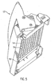
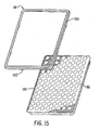
- Figure 5 shows the heated cover 57.
- the heated cover applies pressure to the sample vial caps to ensure that they remain tightly closed when the sample is heated.
- the cover is heated under computer control to a temperature above that of the sample to ensure that the liquid does not condense onto the tube cap and instead remains in the bottom of the tube where thermal cycling occurs.
- the heated platen 54 in the present invention does not press on the dome of the cap but instead presses on the cap perimeter.
- the platen has a surface shaped in this manner so that optical caps are not distorted by the application of pressure.
- tubes that have been cycled can be directly transferred to an optical reader without the need to change the cap.
- the Joule heating and the Seebeck heat pumping both act to heat the sample block against conduction.
- the Seebeck heat pumping and conduction act against the Joule heating.
- significant power is required to hold the block temperature steady against the flow of heat out of the block by conduction. Therefore even with zero power applied, the block will cool at a significant rate.
- the Seebeck effect increases the cooling obtained.
- the joule effect which is proportional to the square of the current, quickly starts to take over acting against the Seebeck cooling. Therefore a point is reached where applying additional power acts against the required effect of cooling. In the heating mode these two effects act together against conduction and no ceiling is reached.
- the heating power vs. input current is approximately linear. This is why the design criteria centers around meeting the cooling rate requirements; the heating rate can always be achieved by the application of more power.
- Equation 1 The solution to equation 1 is used to determine the current value, I, which will result in the desired Q under the current temperature conditions. This process is repeated periodically during temperature transitions.
- the sample has a time constant with respect to the block temperature that is a function of the sample tube and tube geometry which, because the tube is an industry standard, cannot be reduced. This means that even if the sample tube wall temperature is changed as a step function e.g. by immersion in a water bath, the sample will have a finite ramp time as the sample temperature exponentially approaches the set point. This can be compensated for by dynamically causing the block to overshoot the programmed temperature in a controlled manner.
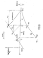
- Figure 8 is a chart for predicting and compensating for temperature overshoots and undershoots.
- Tbn+1 Ts n + 1 - Ts n * 0.174 / RC
- Tsf n Tb n - Ts n - mRC ⁇ 1 - e - tm / RC + mtr n + Ts n
- Tb the measured block temperature
- Ts is the calculated sample temperature
- Tsf the final calculated sample temperature if the block is ramped down at time t n
- R is the thermal resistance between the sample block and the sample
- C the thermal capacitance of the sample
- m is the slope of a line defined by the points Tb and Tsf and tr is the time for the sample block to return to the set point if the system caused it
- the system causes the sample block to ramp back to the set point at the same rate it was ramping away. If the resulting Tsf n is outside the particular error window then the system causes the sample block to continue to ramp away from the set point at the same rate. While ramping back toward the set point the same proportional integral derivative (PID) control loop described above is applied.
- PID proportional integral derivative
- the coefficients are recalculated at the beginning of each PCR protocol to account for the currently selected sample volume.
- TSmp and TPlastic are recalculated for every iteration of the control task.
- Tblk is determined using the equation for TSmp.
- Tblk ⁇ 0 Tsmp - coef ⁇ 1 * TCvr ⁇ 0 - coef ⁇ 2 * TPlastic ⁇ 0 - coef ⁇ 4 * slope - coef ⁇ 5 * TSmp ⁇ 0 / coef ⁇ 3
- the control software includes calibration diagnostics which permit variation in the performance of thermoelectric coolers from instrument to instrument to be compensated for so that all instruments perform identically.
- the sample block, thermal electric devices and heatsink are assembled together and clamped using the clamping mechanism described above.
- the assembly is then ramped through a series of known temperature profiles during which its actual performance is compared to the specified performance. Adjustments are made to the power supplied to the thermal electric devices and the process is repeated until actual performance matches the specification.
- the thermal characteristics obtained during this characterization process are then stored in a memory device residing on the assembly. This allows the block assembly to be moved from instrument to instrument and still perform within specifications.
- the typical failure mode for the thermal electric devices is an increase in resistance caused by a fatigue failure in a solder joint. This results in an increase in the temperature of that joint which stresses the joint further, rapidly leading to catastrophic failure. It has been determined empirically that devices that exhibit an increase in AC resistance of approximately 5% after about 20,000 to 50,000 temperature cycles will shortly fail. The AC resistance of the thermal electric devices are monitored by the instrument to detect imminent failures before the device in question causes a thermal uniformity problem.
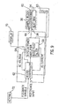
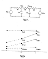
- Figure 9 shows the sample block 36, a layer of thermal electric device 60 and heatsink 34 interfaced with the system microcontroller 62 and bipolar power amplifier 64.
- the temperature sensor already present in the heatsink 38 and an additional temperature sensor attached to the sample block 36 with a clip (not shown) formed of music wire are utilized to determine the temperature differential of the surfaces of the thermal electric device.
- the bipolar power amplifier supplies current in two directions to the device. Current in one direction heats the sample block and current in the other direction cools the sample block.
- the bipolar power amplifier also has signal conditioning capability to measure the AC voltage and AC current supplied to the thermal electric device.
- a band pass filter 68 is incorporated into the signal conditioning to separate an AC measurement signal from the steady state signal that produces a null condition for the temperature difference across the thermal electric device.
- the micro-controller incorporates the necessary capability to process the measurement information and perform the feedback in real time. It also stores the time history of the AC resistance and the number of temperature cycles of the thermal electric device and displays the information to the operator on the display 70.
- the AC measurement is normally done during initial turn on. However, it can be activated when self diagnostics are invoked by the operator using the keypad 72.
- An analog to digital and digital to analog converter along with signal conditioning for the temperature sensors and AC resistance measurement is also integrated into the micro-controller in order for it to perform its digital signal processing.
- the seal 98 is installed by first applying RTV rubber (not shown) around the perimeter 110 of the upper portion of the sample block. The seal 98 is then placed on the RTV rubber. More RTV rubber is applied to the perimeter 120 of the seal and then a cover (not shown) is installed which contacts the RTV rubber - seal combination. The cover has a skirt which also contacts a gasket (not shown) on the printed circuit board to effect a more effective seal.
Landscapes
- Chemical & Material Sciences (AREA)
- Health & Medical Sciences (AREA)
- Chemical Kinetics & Catalysis (AREA)
- General Physics & Mathematics (AREA)
- Physics & Mathematics (AREA)
- General Health & Medical Sciences (AREA)
- Clinical Laboratory Science (AREA)
- Molecular Biology (AREA)
- Analytical Chemistry (AREA)
- Hematology (AREA)
- Biochemistry (AREA)
- Life Sciences & Earth Sciences (AREA)
- Engineering & Computer Science (AREA)
- Automation & Control Theory (AREA)
- Apparatus Associated With Microorganisms And Enzymes (AREA)
- Measuring Or Testing Involving Enzymes Or Micro-Organisms (AREA)
- Saccharide Compounds (AREA)
- Investigating Or Analyzing Materials Using Thermal Means (AREA)
- Preparation Of Compounds By Using Micro-Organisms (AREA)
- Automatic Analysis And Handling Materials Therefor (AREA)
- Physical Or Chemical Processes And Apparatus (AREA)
Applications Claiming Priority (7)
| Application Number | Priority Date | Filing Date | Title |
|---|---|---|---|
| US4175497P | 1997-03-28 | 1997-03-28 | |
| US4612297P | 1997-05-09 | 1997-05-09 | |
| EP98913265A EP0963250B1 (fr) | 1997-03-28 | 1998-03-30 | Ameliorations apportees a un cycleur thermique pour pcr |
| EP01112394A EP1127619B1 (fr) | 1997-03-28 | 1998-03-30 | Dispositif d'un thermocycleur pour réactions d'amplification par polymèrase |
| EP09016131.6A EP2186568B1 (fr) | 1997-03-28 | 1998-03-30 | Ensemble pour cycleur thermique pour PCR |
| EP03022672A EP1386666B1 (fr) | 1997-03-28 | 1998-03-30 | Ameliorations apportees à un cycleur thermique pour PCR |
| EP09006229A EP2090366B1 (fr) | 1997-03-28 | 1998-03-30 | Améliorations dans le cycle thermique pour PCR |
Related Parent Applications (5)
| Application Number | Title | Priority Date | Filing Date |
|---|---|---|---|
| EP03022672A Division EP1386666B1 (fr) | 1997-03-28 | 1998-03-30 | Ameliorations apportees à un cycleur thermique pour PCR |
| EP01112394A Division EP1127619B1 (fr) | 1997-03-28 | 1998-03-30 | Dispositif d'un thermocycleur pour réactions d'amplification par polymèrase |
| EP09006229A Division EP2090366B1 (fr) | 1997-03-28 | 1998-03-30 | Améliorations dans le cycle thermique pour PCR |
| EP09016131.6A Division EP2186568B1 (fr) | 1997-03-28 | 1998-03-30 | Ensemble pour cycleur thermique pour PCR |
| EP98913265A Division EP0963250B1 (fr) | 1997-03-28 | 1998-03-30 | Ameliorations apportees a un cycleur thermique pour pcr |
Publications (1)
| Publication Number | Publication Date |
|---|---|
| EP2913109A1 true EP2913109A1 (fr) | 2015-09-02 |
Family
ID=26718481
Family Applications (5)
| Application Number | Title | Priority Date | Filing Date |
|---|---|---|---|
| EP14198058.1A Withdrawn EP2913109A1 (fr) | 1997-03-28 | 1998-03-30 | Ensemble thermocycleur pour PCR |
| EP98913265A Expired - Lifetime EP0963250B1 (fr) | 1997-03-28 | 1998-03-30 | Ameliorations apportees a un cycleur thermique pour pcr |
| EP09016131.6A Expired - Lifetime EP2186568B1 (fr) | 1997-03-28 | 1998-03-30 | Ensemble pour cycleur thermique pour PCR |
| EP09013036.0A Expired - Lifetime EP2156892B1 (fr) | 1997-03-28 | 1998-03-30 | Cycleur thermique pour PCR |
| EP09006229A Expired - Lifetime EP2090366B1 (fr) | 1997-03-28 | 1998-03-30 | Améliorations dans le cycle thermique pour PCR |
Family Applications After (4)
| Application Number | Title | Priority Date | Filing Date |
|---|---|---|---|
| EP98913265A Expired - Lifetime EP0963250B1 (fr) | 1997-03-28 | 1998-03-30 | Ameliorations apportees a un cycleur thermique pour pcr |
| EP09016131.6A Expired - Lifetime EP2186568B1 (fr) | 1997-03-28 | 1998-03-30 | Ensemble pour cycleur thermique pour PCR |
| EP09013036.0A Expired - Lifetime EP2156892B1 (fr) | 1997-03-28 | 1998-03-30 | Cycleur thermique pour PCR |
| EP09006229A Expired - Lifetime EP2090366B1 (fr) | 1997-03-28 | 1998-03-30 | Améliorations dans le cycle thermique pour PCR |
Country Status (7)
| Country | Link |
|---|---|
| EP (5) | EP2913109A1 (fr) |
| JP (5) | JP2001521379A (fr) |
| AT (2) | ATE251496T1 (fr) |
| AU (1) | AU736484B2 (fr) |
| CA (1) | CA2285377C (fr) |
| DE (2) | DE69803041T2 (fr) |
| WO (1) | WO1998043740A2 (fr) |
Families Citing this family (83)
| Publication number | Priority date | Publication date | Assignee | Title |
|---|---|---|---|---|
| GB0007219D0 (en) * | 2000-03-24 | 2000-05-17 | Bjs Company Ltd | Heating specimen carriers |
| US7133726B1 (en) | 1997-03-28 | 2006-11-07 | Applera Corporation | Thermal cycler for PCR |
| WO1999048608A2 (fr) * | 1998-03-23 | 1999-09-30 | Cepheid | Systeme de reacteur multi-site a commande dynamique independante de sites de reaction individuels |
| US6780617B2 (en) | 2000-12-29 | 2004-08-24 | Chen & Chen, Llc | Sample processing device and method |
| CA2301153C (fr) | 1998-06-24 | 2008-08-26 | Chen & Chen, Llc | Dispositif d'analyse d'echantillons de fluide |
| EP1045038A1 (fr) * | 1999-04-08 | 2000-10-18 | Hans-Knöll-Institut Für Naturstoff-Forschung E.V. | Thermocycleur à bloc de régulation rapide |
| US6657169B2 (en) | 1999-07-30 | 2003-12-02 | Stratagene | Apparatus for thermally cycling samples of biological material with substantial temperature uniformity |
| EP1088590B1 (fr) | 1999-09-29 | 2003-04-16 | Tecan Trading AG | Thermocycleur et élément de levage pour plaque de microtitrage |
| DE29917313U1 (de) * | 1999-10-01 | 2001-02-15 | MWG-BIOTECH AG, 85560 Ebersberg | Vorrichtung zur Durchführung chemischer oder biologischer Reaktionen |
| US6699713B2 (en) | 2000-01-04 | 2004-03-02 | The Regents Of The University Of California | Polymerase chain reaction system |
| US7169355B1 (en) * | 2000-02-02 | 2007-01-30 | Applera Corporation | Apparatus and method for ejecting sample well trays |
| AU2002223503A1 (en) * | 2000-11-24 | 2002-06-03 | Novo-Nordisk A/S | Decondenser unit |
| JP2004534386A (ja) * | 2001-04-09 | 2004-11-11 | リサーチ・トライアングル・インスティチュート | Dnaゲノムチップ、プロテオームチップ、熱光スイッチング回路および赤外線タグ用薄膜熱電加熱冷却装置 |
| WO2003000419A2 (fr) * | 2001-06-21 | 2003-01-03 | Hybaid Limited | Plaque a puits a echantillons |
| EP1421455A1 (fr) * | 2001-06-27 | 2004-05-26 | AB Implementa Hebe | Dispositif destine a effectuer un traitement dans un milieu de traitement |
| EP1409137A2 (fr) * | 2001-07-13 | 2004-04-21 | University of British Columbia | Procedes et appareils de cyclage thermique |
| JP4513085B2 (ja) | 2001-09-11 | 2010-07-28 | アイキューム インク | 試料の容器 |
| US7342169B2 (en) | 2001-10-05 | 2008-03-11 | Nextreme Thermal Solutions | Phonon-blocking, electron-transmitting low-dimensional structures |
| CA2482363C (fr) | 2002-04-15 | 2011-06-14 | Research Triangle Institute | Dispositif thermoelectrique utilisant des jonctions peltier double face et procede de fabrication de ce dispositif |
| US7452712B2 (en) * | 2002-07-30 | 2008-11-18 | Applied Biosystems Inc. | Sample block apparatus and method of maintaining a microcard on a sample block |
| WO2005058501A1 (fr) * | 2002-09-09 | 2005-06-30 | Bjs Company Ltd | Chauffage d'echantillons dans un porte-echantillons |
| US6730883B2 (en) | 2002-10-02 | 2004-05-04 | Stratagene | Flexible heating cover assembly for thermal cycling of samples of biological material |
| US8676383B2 (en) * | 2002-12-23 | 2014-03-18 | Applied Biosystems, Llc | Device for carrying out chemical or biological reactions |
| ES2604352T3 (es) | 2003-02-05 | 2017-03-06 | Iquum, Inc. | Procesado de muestras |
| WO2004105947A2 (fr) | 2003-05-23 | 2004-12-09 | Bio-Rad Laboratories, Inc. | Controle de temperature localise pour ensemble spatial de milieux reactionnels |
| US20050221358A1 (en) * | 2003-09-19 | 2005-10-06 | Carrillo Albert L | Pressure chamber clamp mechanism |
| US20050226779A1 (en) | 2003-09-19 | 2005-10-13 | Oldham Mark F | Vacuum assist for a microplate |
| US7638705B2 (en) | 2003-12-11 | 2009-12-29 | Nextreme Thermal Solutions, Inc. | Thermoelectric generators for solar conversion and related systems and methods |
| US7659109B2 (en) | 2004-05-17 | 2010-02-09 | Applied Biosystems, Llc | Pasting edge heater |
| EP1637228A1 (fr) * | 2004-09-16 | 2006-03-22 | Roche Diagnostics GmbH | Procédé et dispositif pour réaliser des cyclages thermiques rapides et systeme microfluidique |
| US7523617B2 (en) | 2004-10-22 | 2009-04-28 | Nextreme Thermal Solutions, Inc. | Thin film thermoelectric devices for hot-spot thermal management in microprocessors and other electronics |
| US8063298B2 (en) | 2004-10-22 | 2011-11-22 | Nextreme Thermal Solutions, Inc. | Methods of forming embedded thermoelectric coolers with adjacent thermally conductive fields |
| WO2007002337A2 (fr) | 2005-06-22 | 2007-01-04 | Nextreme Thermal Solutions | Procedes permettant de former des dispositifs thermoelectriques comprenant des bornes conductrices et/ou differents materiaux de soudure et procedes et structures associes |
| WO2007002342A2 (fr) | 2005-06-22 | 2007-01-04 | Nextreme Thermal Solutions | Procédés de fabrication de dispositifs thermoélectriques comprenant des matrices électriquement isolantes entre les traces conductrices et structures associées |
| US7679203B2 (en) | 2006-03-03 | 2010-03-16 | Nextreme Thermal Solutions, Inc. | Methods of forming thermoelectric devices using islands of thermoelectric material and related structures |
| US7958736B2 (en) * | 2007-05-24 | 2011-06-14 | Bio-Rad Laboratories, Inc. | Thermoelectric device and heat sink assembly with reduced edge heat loss |
| EP2060324A1 (fr) * | 2007-11-13 | 2009-05-20 | F.Hoffmann-La Roche Ag | Unité de bloc thermique |
| EP2255010B1 (fr) | 2008-02-20 | 2018-05-30 | Streck Inc. | Thermocycleur et récipient à échantillons pour l'amplification rapide de l'adn |
| US8900853B2 (en) | 2008-09-23 | 2014-12-02 | Koninklijke Philips N.V. | Thermocycling device |
| CN101735949B (zh) * | 2008-11-05 | 2012-10-10 | 广达电脑股份有限公司 | 变温装置 |
| GB2511692A (en) * | 2009-08-08 | 2014-09-10 | Bibby Scient Ltd | An apparatus for treating a test sample |
| GB2512764B (en) * | 2009-08-08 | 2014-12-24 | Bibby Scient Ltd | An apparatus for treating a test sample |
| US20120270309A1 (en) * | 2009-08-20 | 2012-10-25 | Takara Bio Inc. | Thermal cycler |
| EP2473893B1 (fr) | 2009-09-01 | 2021-07-28 | Life Technologies Corporation | Ensembles blocs thermiques et instruments fournissant une non-uniformité thermique faible pour un cycle thermique rapide |
| EP2338594A1 (fr) * | 2009-12-23 | 2011-06-29 | PEQLAB Biotechnologie GmbH | Plaque thermique |
| US9601677B2 (en) | 2010-03-15 | 2017-03-21 | Laird Durham, Inc. | Thermoelectric (TE) devices/structures including thermoelectric elements with exposed major surfaces |
| CN103003448B (zh) | 2010-04-09 | 2015-06-17 | 生命技术公司 | 使用动态控制改进热循环仪的热均匀性 |
| DE102010019231A1 (de) | 2010-05-03 | 2014-03-06 | Eppendorf Ag | Verbindung für einen temperierbaren Wechselblock |
| GB201009998D0 (en) * | 2010-06-15 | 2010-07-21 | Bg Res | Cell disruption |
| JP2013535193A (ja) * | 2010-07-23 | 2013-09-12 | ベックマン コールター, インコーポレイテッド | 分析装置を含むシステムおよび方法 |
| US9446410B2 (en) * | 2010-12-03 | 2016-09-20 | Biofire Defense, Llc | Thermal cycler apparatus with elastomeric adhesive |
| EP2500957B1 (fr) * | 2011-03-17 | 2015-08-26 | Braun GmbH | Procédé de test d'un élément Peltier ainsi qu'un petit appareil électrique avec un élément Peltier et dispositif de sécurité |
| CA2835654A1 (fr) | 2011-06-01 | 2012-12-06 | Streck, Inc. | Systeme thermocycleur rapide pour une amplification rapide d'acides nucleiques et procedes s'y rapportant |
| DE202011101712U1 (de) | 2011-06-10 | 2012-09-13 | Eppendorf Ag | Labortemperierapparat mit Formkörpereinrichtung |
| JP5703377B2 (ja) | 2011-06-24 | 2015-04-15 | 株式会社日立ハイテクノロジーズ | 核酸増幅装置及び核酸分析装置 |
| CN103243017B (zh) * | 2012-02-09 | 2015-04-29 | 卡尤迪生物科技(北京)有限公司 | 利用整体结构储热和散热的薄型pcr仪 |
| JP5935980B2 (ja) * | 2012-03-28 | 2016-06-15 | セイコーエプソン株式会社 | 熱サイクル装置 |
| JP5935981B2 (ja) * | 2012-03-28 | 2016-06-15 | セイコーエプソン株式会社 | 熱サイクル装置 |
| RU2643937C2 (ru) | 2012-06-28 | 2018-02-06 | Флюоресентрик, Инк. | Устройство для обнаружения химического индикатора |
| EP2883039A1 (fr) | 2012-08-10 | 2015-06-17 | Streck Inc. | Système optique en temps réel pour réaction en chaîne par polymérase |
| JP2014143927A (ja) | 2013-01-28 | 2014-08-14 | Hitachi High-Technologies Corp | 核酸増幅装置および温度調節機能の異常検出方法 |
| BR112015023882A2 (pt) | 2013-03-19 | 2017-07-18 | Life Technologies Corp | tampa de ciclador térmico |
| US10006861B2 (en) | 2013-06-28 | 2018-06-26 | Streck, Inc. | Devices for real-time polymerase chain reaction |
| JP2015053893A (ja) * | 2013-09-11 | 2015-03-23 | 公益財団法人神奈川科学技術アカデミー | 高速遺伝子増幅検出装置 |
| WO2015039014A1 (fr) | 2013-09-16 | 2015-03-19 | Life Technologies Corporation | Appareils, systèmes et procédés de fourniture d'uniformité thermique de thermocycleur |
| CN103675454B (zh) * | 2013-10-31 | 2015-12-30 | 成都金采科技有限公司 | 电阻测试装置 |
| JP6535679B2 (ja) | 2014-02-18 | 2019-06-26 | ライフ テクノロジーズ コーポレーション | 拡張可能なサーマルサイクラーの提供及び熱電デバイスの隔離のための装置、システム、及び方法 |
| DE112015005925B4 (de) | 2015-02-23 | 2023-06-15 | Hitachi High-Tech Corporation | Nucleinsäure-Analysator |
| JP6856619B2 (ja) * | 2015-07-23 | 2021-04-07 | セフェィド | 熱制御装置、使用方法、及び熱管理システム |
| JP6576750B2 (ja) * | 2015-09-04 | 2019-09-18 | Phcホールディングス株式会社 | 核酸増幅装置 |
| GB2561446B (en) * | 2015-09-09 | 2022-08-24 | Hitachi High Tech Corp | Temperature adjustment apparatus |
| US11583862B2 (en) | 2015-09-15 | 2023-02-21 | Life Technologies Corporation | Systems and methods for biological analysis |
| EP3349902B1 (fr) * | 2015-09-15 | 2021-05-26 | Life Technologies Corporation | Système d'analyse biologique |
| IL299626A (en) | 2015-10-01 | 2023-03-01 | Berkeley Lights Inc | Multi-well plate incubator |
| JP2017093319A (ja) * | 2015-11-19 | 2017-06-01 | 積水化学工業株式会社 | 核酸の増幅方法 |
| DE102015121362B4 (de) | 2015-12-08 | 2018-05-24 | Analytik Jena Ag | Temperiervorrichtung mit einem Reaktionsgefäß |
| KR102546384B1 (ko) | 2016-12-01 | 2023-06-21 | 버클리 라잇츠, 인크. | 웰 플레이트 인큐베이터 |
| DE102017205857B3 (de) | 2017-04-06 | 2018-06-07 | Audi Ag | Kühleinrichtung, insbesondere für Elektronikbauteile, und Elektronikanordnung damit |
| IT201700089430A1 (it) | 2017-08-03 | 2019-02-03 | Petroceramics S P A | Materiale composito fibro-rinforzato pre-impregnato e manufatto ottenuto per formatura e completo indurimento di detto materiale composito fibro-rinforzato pre-impregnato |
| IT201700089373A1 (it) | 2017-08-03 | 2019-02-03 | Petroceramics S P A | Materiale composito fibro-rinforzato pre-impregnato e materiale composito ceramico fibro-rinforzato, ottenuto per formatura e successiva pirolisi di detto materiale pre-impregnato |
| GB201812192D0 (en) * | 2018-07-26 | 2018-09-12 | Ttp Plc | Variable temperature reactor, heater and control circuit for the same |
| CN110205242B (zh) * | 2019-06-18 | 2024-04-26 | 苏州锐讯生物科技有限公司 | 一种快速实现数字pcr反应的微流控芯片组件及其应用 |
| US20240419198A1 (en) * | 2023-06-16 | 2024-12-19 | Saebom LEE | Intelligent temperature control method and system of heating and/or cooling apparatus |
Citations (3)
| Publication number | Priority date | Publication date | Assignee | Title |
|---|---|---|---|---|
| US5038852A (en) * | 1986-02-25 | 1991-08-13 | Cetus Corporation | Apparatus and method for performing automated amplification of nucleic acid sequences and assays using heating and cooling steps |
| EP0488769A2 (fr) * | 1990-11-29 | 1992-06-03 | The Perkin-Elmer Corporation | Dispositif à cycles thermiques pour l'exécution automatique de réactions en chaine de polymérase à régulation précise de température |
| US5441576A (en) | 1993-02-01 | 1995-08-15 | Bierschenk; James L. | Thermoelectric cooler |
Family Cites Families (24)
| Publication number | Priority date | Publication date | Assignee | Title |
|---|---|---|---|---|
| US4639883A (en) * | 1984-11-28 | 1987-01-27 | Rca Corporation | Thermoelectric cooling system and method |
| CA1339653C (fr) * | 1986-02-25 | 1998-02-03 | Larry J. Johnson | Appareil servant a l'amplification automatisee de sequences nucleotidiques et d'essais au moyen de cycle de chauffage et de refroidissement |
| US5237821A (en) * | 1987-08-20 | 1993-08-24 | Kabushiki Kaisha Komatsu Seisakusho | Multistep electronic cooler |
| EP0342155A3 (fr) * | 1988-05-13 | 1990-06-27 | Agrogen-Stiftung | Appareil de laboratoire pour chauffer ou refroidir à volonté |
| US4881038A (en) * | 1988-05-25 | 1989-11-14 | Champlin Keith S | Electric battery testing device with automatic voltage scaling to determine dynamic conductance |
| SE464595B (sv) * | 1988-09-29 | 1991-05-13 | Ffv Aerotech Ab | Saett att med ett peltier-element med tvaa ytor bestaemma den ena eller baada ytornas temperatur |
| US4865986A (en) * | 1988-10-06 | 1989-09-12 | Coy Corporation | Temperature control apparatus |
| DE4037955A1 (de) * | 1989-12-05 | 1991-06-06 | Bernd Seidl | Vorrichtung zur aufnahme von probenbehaeltnissen |
| US5040381A (en) * | 1990-04-19 | 1991-08-20 | Prime Computer, Inc. | Apparatus for cooling circuits |
| GB9123463D0 (en) * | 1991-11-05 | 1991-12-18 | Hybaid Ltd | Reaction temperature control device |
| US5248934A (en) * | 1992-01-10 | 1993-09-28 | Roveti Denes K | Method and apparatus for converting a conventional DC multimeter to an AC impedance meter |
| AU5683294A (en) * | 1992-11-27 | 1994-06-22 | Pneumo Abex Corporation | Thermoelectric device for heating and cooling air for human use |
| JP3113446B2 (ja) * | 1993-03-26 | 2000-11-27 | 三洋電機株式会社 | インキュベータ |
| CA2129787A1 (fr) * | 1993-08-27 | 1995-02-28 | Russell G. Higuchi | Surveillance de plusieurs reactions d'amplification simultanement et analyse de ces reactions simultanement |
| US5385022A (en) * | 1993-09-09 | 1995-01-31 | Kornblit; Levy | Apparatus and method for deep thermoelectric refrigeration |
| CA2130517C (fr) * | 1993-09-10 | 1999-10-05 | Walter Fassbind | Reseau de microplateaux pour appareil de production automatique de cycles de temperatures |
| CA2130013C (fr) * | 1993-09-10 | 1999-03-30 | Rolf Moser | Appareil servant a modifier automatiquement la temperature du contenu de differentes eprouvettes |
| US5511415A (en) | 1994-01-18 | 1996-04-30 | Cambridge Aeroflow, Inc. | Gas flow and temperature probe and gas flow and temperature monitor system including one or more such probes |
| GB9406537D0 (en) * | 1994-03-31 | 1994-05-25 | British Aerospace | Blind stitching apparatus and composite material manufacturing methods |
| WO1995027196A1 (fr) * | 1994-04-04 | 1995-10-12 | Sanadi Ashok R | Procede et appareil destine a empecher la contamination croisee de plaques de test a cupules multiples |
| US5410130A (en) * | 1994-04-20 | 1995-04-25 | Ericomp, Inc. | Heating and temperature cycling |
| US5972716A (en) * | 1994-04-29 | 1999-10-26 | The Perkin-Elmer Corporation | Fluorescence monitoring device with textured optical tube and method for reducing background fluorescence |
| US5600575A (en) * | 1994-10-05 | 1997-02-04 | Anticole; Robert B. | Drive protection monitor for motor and amplifier |
| US5856174A (en) * | 1995-06-29 | 1999-01-05 | Affymetrix, Inc. | Integrated nucleic acid diagnostic device |
-
1998
- 1998-03-30 AU AU67861/98A patent/AU736484B2/en not_active Ceased
- 1998-03-30 DE DE69803041T patent/DE69803041T2/de not_active Expired - Lifetime
- 1998-03-30 JP JP54188598A patent/JP2001521379A/ja not_active Withdrawn
- 1998-03-30 EP EP14198058.1A patent/EP2913109A1/fr not_active Withdrawn
- 1998-03-30 CA CA002285377A patent/CA2285377C/fr not_active Expired - Fee Related
- 1998-03-30 WO PCT/US1998/006189 patent/WO1998043740A2/fr not_active Ceased
- 1998-03-30 DE DE69818869T patent/DE69818869T2/de not_active Expired - Lifetime
- 1998-03-30 EP EP98913265A patent/EP0963250B1/fr not_active Expired - Lifetime
- 1998-03-30 EP EP09016131.6A patent/EP2186568B1/fr not_active Expired - Lifetime
- 1998-03-30 AT AT01112394T patent/ATE251496T1/de not_active IP Right Cessation
- 1998-03-30 EP EP09013036.0A patent/EP2156892B1/fr not_active Expired - Lifetime
- 1998-03-30 AT AT98913265T patent/ATE211025T1/de not_active IP Right Cessation
- 1998-03-30 EP EP09006229A patent/EP2090366B1/fr not_active Expired - Lifetime
-
2008
- 2008-07-22 JP JP2008189231A patent/JP5058908B2/ja not_active Expired - Lifetime
-
2010
- 2010-02-15 JP JP2010030714A patent/JP5780707B2/ja not_active Expired - Lifetime
-
2012
- 2012-06-29 JP JP2012146977A patent/JP2012187124A/ja not_active Withdrawn
-
2014
- 2014-11-17 JP JP2014232286A patent/JP5996613B2/ja not_active Expired - Lifetime
Patent Citations (4)
| Publication number | Priority date | Publication date | Assignee | Title |
|---|---|---|---|---|
| US5038852A (en) * | 1986-02-25 | 1991-08-13 | Cetus Corporation | Apparatus and method for performing automated amplification of nucleic acid sequences and assays using heating and cooling steps |
| EP0488769A2 (fr) * | 1990-11-29 | 1992-06-03 | The Perkin-Elmer Corporation | Dispositif à cycles thermiques pour l'exécution automatique de réactions en chaine de polymérase à régulation précise de température |
| US5475610A (en) | 1990-11-29 | 1995-12-12 | The Perkin-Elmer Corporation | Thermal cycler for automatic performance of the polymerase chain reaction with close temperature control |
| US5441576A (en) | 1993-02-01 | 1995-08-15 | Bierschenk; James L. | Thermoelectric cooler |
Also Published As
| Publication number | Publication date |
|---|---|
| EP2156892A3 (fr) | 2010-03-03 |
| CA2285377C (fr) | 2004-08-17 |
| DE69818869T2 (de) | 2004-09-09 |
| DE69818869D1 (de) | 2003-11-13 |
| JP5780707B2 (ja) | 2015-09-16 |
| JP5996613B2 (ja) | 2016-09-21 |
| EP2156892B1 (fr) | 2013-05-08 |
| EP2090366A3 (fr) | 2009-11-18 |
| WO1998043740A2 (fr) | 1998-10-08 |
| EP0963250B1 (fr) | 2001-12-19 |
| DE69803041T2 (de) | 2002-07-11 |
| EP2186568A1 (fr) | 2010-05-19 |
| DE69803041D1 (de) | 2002-01-31 |
| EP0963250A2 (fr) | 1999-12-15 |
| JP2012187124A (ja) | 2012-10-04 |
| JP2015097526A (ja) | 2015-05-28 |
| AU6786198A (en) | 1998-10-22 |
| WO1998043740A3 (fr) | 1998-12-17 |
| JP2008278896A (ja) | 2008-11-20 |
| JP2001521379A (ja) | 2001-11-06 |
| ATE211025T1 (de) | 2002-01-15 |
| EP2090366B1 (fr) | 2012-12-19 |
| ATE251496T1 (de) | 2003-10-15 |
| EP2090366A2 (fr) | 2009-08-19 |
| EP2156892A2 (fr) | 2010-02-24 |
| JP5058908B2 (ja) | 2012-10-24 |
| JP2010104382A (ja) | 2010-05-13 |
| EP2186568B1 (fr) | 2014-12-17 |
| CA2285377A1 (fr) | 1998-10-08 |
| AU736484B2 (en) | 2001-07-26 |
Similar Documents
| Publication | Publication Date | Title |
|---|---|---|
| EP2186568B1 (fr) | Ensemble pour cycleur thermique pour PCR | |
| US7133726B1 (en) | Thermal cycler for PCR | |
| WO1998043740A9 (fr) | Ameliorations apportees a un cycleur thermique pour pcr | |
| EP3870961B1 (fr) | Calorimètre à compensation de puissance à haut débit d'échantillon | |
| EP1386666B1 (fr) | Ameliorations apportees à un cycleur thermique pour PCR | |
| EP1127619B1 (fr) | Dispositif d'un thermocycleur pour réactions d'amplification par polymèrase | |
| CA2464973A1 (fr) | Cycleur thermique pour pcr | |
| AU2024343839A1 (en) | Thermal control device for temperature cycling, method for controlling temperature cycling using a thermal control device, and system for controlling temperature of a sample using a thermal control device |
Legal Events
| Date | Code | Title | Description |
|---|---|---|---|
| PUAI | Public reference made under article 153(3) epc to a published international application that has entered the european phase |
Free format text: ORIGINAL CODE: 0009012 |
|
| AC | Divisional application: reference to earlier application |
Ref document number: 1127619 Country of ref document: EP Kind code of ref document: P Ref document number: 2090366 Country of ref document: EP Kind code of ref document: P Ref document number: 1386666 Country of ref document: EP Kind code of ref document: P Ref document number: 2186568 Country of ref document: EP Kind code of ref document: P Ref document number: 0963250 Country of ref document: EP Kind code of ref document: P |
|
| AK | Designated contracting states |
Kind code of ref document: A1 Designated state(s): AT BE CH DE DK ES FI FR GB GR IE IT LI LU MC NL PT SE |
|
| 17P | Request for examination filed |
Effective date: 20160301 |
|
| RBV | Designated contracting states (corrected) |
Designated state(s): AT BE CH DE DK ES FI FR GB GR IE IT LI LU MC NL PT SE |
|
| RIN1 | Information on inventor provided before grant (corrected) |
Inventor name: OLSEN, DOUGLAS E. Inventor name: WITTMER, CHARLES M. Inventor name: NOREIKS, RICHARD W. Inventor name: HETHERINGTON, PAUL M. Inventor name: ATWOOD, JOHN G. Inventor name: WIDOMSKI, JOHN R. Inventor name: FAWCETT, ADRIAN Inventor name: FERRARA, KEITH S |
|
| 17Q | First examination report despatched |
Effective date: 20180705 |
|
| STAA | Information on the status of an ep patent application or granted ep patent |
Free format text: STATUS: THE APPLICATION IS DEEMED TO BE WITHDRAWN |
|
| 18D | Application deemed to be withdrawn |
Effective date: 20181116 |