EP2913166A1 - Couteau et ciseaux dotés d'un moyen de protection - Google Patents
Couteau et ciseaux dotés d'un moyen de protection Download PDFInfo
- Publication number
- EP2913166A1 EP2913166A1 EP13848971.1A EP13848971A EP2913166A1 EP 2913166 A1 EP2913166 A1 EP 2913166A1 EP 13848971 A EP13848971 A EP 13848971A EP 2913166 A1 EP2913166 A1 EP 2913166A1
- Authority
- EP
- European Patent Office
- Prior art keywords
- protrusion
- knife
- insertion portion
- upper blade
- distal end
- Prior art date
- Legal status (The legal status is an assumption and is not a legal conclusion. Google has not performed a legal analysis and makes no representation as to the accuracy of the status listed.)
- Withdrawn
Links
Images


Classifications
-
- B—PERFORMING OPERATIONS; TRANSPORTING
- B26—HAND CUTTING TOOLS; CUTTING; SEVERING
- B26B—HAND-HELD CUTTING TOOLS NOT OTHERWISE PROVIDED FOR
- B26B29/00—Guards or sheaths or guides for hand cutting tools; Arrangements for guiding hand cutting tools
- B26B29/02—Guards or sheaths for knives
-
- B—PERFORMING OPERATIONS; TRANSPORTING
- B26—HAND CUTTING TOOLS; CUTTING; SEVERING
- B26B—HAND-HELD CUTTING TOOLS NOT OTHERWISE PROVIDED FOR
- B26B29/00—Guards or sheaths or guides for hand cutting tools; Arrangements for guiding hand cutting tools
-
- A—HUMAN NECESSITIES
- A22—BUTCHERING; MEAT TREATMENT; PROCESSING POULTRY OR FISH
- A22C—PROCESSING MEAT, POULTRY, OR FISH
- A22C25/00—Processing fish ; Curing of fish; Stunning of fish by electric current; Investigating fish by optical means
- A22C25/006—Hand tools for processing fish
-
- B—PERFORMING OPERATIONS; TRANSPORTING
- B26—HAND CUTTING TOOLS; CUTTING; SEVERING
- B26B—HAND-HELD CUTTING TOOLS NOT OTHERWISE PROVIDED FOR
- B26B11/00—Hand knives combined with other implements, e.g. with corkscrew, with scissors, with writing implement
- B26B11/006—Several functions combined in the blade
-
- B—PERFORMING OPERATIONS; TRANSPORTING
- B26—HAND CUTTING TOOLS; CUTTING; SEVERING
- B26B—HAND-HELD CUTTING TOOLS NOT OTHERWISE PROVIDED FOR
- B26B29/00—Guards or sheaths or guides for hand cutting tools; Arrangements for guiding hand cutting tools
- B26B29/04—Guards or sheaths for scissors, e.g. combined with manicuring appliances
-
- B—PERFORMING OPERATIONS; TRANSPORTING
- B26—HAND CUTTING TOOLS; CUTTING; SEVERING
- B26B—HAND-HELD CUTTING TOOLS NOT OTHERWISE PROVIDED FOR
- B26B9/00—Blades for hand knives
Definitions
- the present invention relates to a knife and scissors, and more particularly, to a knife and scissors having a protection means that can prevent an unpredicted accident to a user and provide a sense of safety in terms of appearances.
- knives and scissors are widely used as portable consumer cutting devices.
- a typical kitchen knife has only a bottom blade (i.e., single-edged).
- the kitchen knife is used as a tool with which food materials are processed for cooking in a kitchen, for example, vegetables, meat, and fish are cut or various condiments including peppers, garlic, etc. are chopped.
- the blade formed at the bottom of the body of the knife is formed into various shapes such as a straight line or arc, with a wedge-shaped cross section.
- Scissors are a cutting device with two bodies connected by a hinge. As a user moves two handles of the scissors with facing blades upon a hinge so that the handles may approach or move away from each other, the pair of blades are brought into close contact and thus cut an object between them.
- One body of the scissors is formed roughly into a similar shape to a knife blade.
- the body of the knife or the bodies of the scissors are tapered toward its end or their ends along a length direction so that its cross section or their cross sections may decrease toward the end(s).
- the distal end(s) of the body (bodies) are pointed.
- Knives or scissors are often used in a place such as a kitchen and an office in a daily living. Their sharp ends often bring about safety incidents. Moreover, users feel unsafe due to their concerns about safety risks involved in knives or scissors.
- a kitchen knife needs to be used in a reverse direction.
- a user processes a food material having an outer skin to be peeled off, such as seafood or fruit
- the user reverses the knife to point the blade upward and removes the outer skin with the sharp tip of the end of the knife inserted into a specific part of the food material.
- the user generally applies force forward and upward.
- a portable consumer cutting device such as a conventional knife or scissors has a simple structure and thus is readily manufactured and carried, it has a high risk of safety incidents according to its use state. If a safety device is added to the portable consumer cutting device, the portable consumer cutting device is excessively complex in structure and causes higher manufacture cost, which makes it unpractical to add the safety device.
- the present invention is directed to a knife and scissors having a protection means that substantially obviate one or more problems due to limitations and disadvantages of the related art.
- An object of the present invention is to provide a knife and scissors having a protection means which has a simplified structure and minimizes the risk of safety incidents and a sense of unsafety that the looks of the knife and scissors may give.
- Another object of the present invention is to provide a knife and scissors having a protection means which can perform a protection function and a function of guiding to an accurate position at the same time, when the knife and scissors are used.
- a knife with a protection means which has a handle, a body extended in one direction in engagement with the handle, and a body blade formed at the bottom of the body, for performing a cutting action, includes a protrusion spaced upward from a distal end of the body, an insertion portion formed in a space between the body and the protrusion, and an upper blade formed at the bottom of the insertion portion.
- the upper blade cuts an object inserted in the insertion portion and the protrusion protects a human body or the object by contacting the body or the object earlier than the distal end of the body, when the body slips off the object.
- the insertion portion may be shaped into a wedge having a longitudinal width decreased toward the other end of the insertion portion. Accordingly, a thin film or skin of an object can be peeled off efficiently.
- the insertion portion may include an inner blade at its other end. Thus, a cutting action may be performed reliably.
- the insertion portion may further include a lower blade formed at the bottom of the protrusion.
- a downward cutting action and an upward cutting action can be performed effectively, with an object inserted in the insertion portion.
- the protrusion may be wider in forward and backward directions than the body and guide a forward proceeding of the upper blade, in close contact with a surface of the object to be cut, when a cutting action is performed by the upper blade. Therefore, an action accuracy is increased and the risk of safety incidents is minimized.
- the knife may further include a step for protruding the distal end of the body having the upper blade formed therein further than the protrusion in a forward or backward direction. Therefore, even when the knife is used tilted on the object, cutting efficient is increased.
- a side section of the protrusion may be convex downward and when the body is tilted with respect to the object, the protrusion may guide a cutting action of the upper blade by changing the position of a part of the bottom of the protrusion contacting a surface of the object. Therefore, since the way a user grabs the knife can be dealt with, the object can be accurately cut.
- scissors with a protection means which have a first body, a second body, and a hinge connecting the first body to the second body, for cutting an object by rotating the first and second bodies upon the hinge and advancing the first and second bodies toward each other, include a protrusion protruding in one direction, spaced upward from a distal end of the first body, an insertion portion formed between the distal end of the body and the protrusion, and an upper blade formed at the bottom of the insertion portion, for cutting an object.
- the upper blade cuts an object inserted in the insertion portion and the protrusion protects a human body or the object by contacting the body or the object earlier than the distal end of the first or second body, when the first body slips off the object.
- FIG. 1 illustrates a knife having a protection means according to an embodiment of the present invention.
- a knife 100 basically includes a handle 110 having a predetermined diameter, to be grabbed by a user, and a body 120 having a body blade 121 at its bottom, engaged with an end portion of the handle 110.
- the knife 100 is tapered toward one end of the body 120 in such a manner that the cross section of the body 120 may be decreased toward the one end of the body 120. Accordingly, there is a risk of safety incidents for the knife user, as described before. Especially, because the distal end of the knife 100 is pointed, the use of the body blade 121 in an upward reverse sate further increases the risk of safety incidents.
- the present invention provides a knife having a protection means to overcome this problem.
- the knife 100 basically includes a protrusion 130 protruding in one direction from an upper portion of the body 121, an insertion portion 132 formed between the protrusion 130 and one end of the body blade 121, for allowing insertion of an object, and an upper blade 131 formed on the body blade 121 that defines the insertion portion 132.
- the body 120 may be generally formed of an anticorrosive metal such as stainless steel, or a synthetic resin, which should not be construed as limiting the present invention.
- the handle 110 has a thickness large enough to allow the user to grab the handle 110. While the handle 110 is shown in FIG. 1 as shaped into a cylinder roughly convex at its center, various shapes and materials are available for formation of the handle 110.
- the protrusion 130 and the body 120 may be configured as separate members and then combined, it is preferred to integrate the protrusion 130 with the body 120 in consideration of productivity. More preferably, the protrusion 130 and the body 120 may be cast or injection-molded.
- the body blade 121 is formed at the bottom of the body 120.
- the body blade 121 is shaped into a wedge tapered downward with a decreased cross section and functions to cut or chop an object by transferring a pressing force applied by the user to the object over a narrow area.
- the body blade 121 may be extended to the distal end of the body 120. As described before, the distal end of the body 120 120 may be pointed to allow a stabbing motion.
- the protrusion 130 is apart upward from the upper blade 131 with a predetermined spacing in between, protruding in a forward direction from the body 120.
- the protrusion 130 is roughly rectangular, by way of example, when seen from the front.
- the protrusion 130 may be formed selectively into many other shapes. Specific embodiments of the protrusion 130 will be described later with reference to FIGS. 2 and 3 .
- the protrusion 130 preferably protrudes in the one direction further than the distal end of the body 120 having the body blade 121 formed therein. As described before, since the distal end of the body blade 121 is conventionally pointed, there is a risk of safety incidents. Accordingly, if the protrusion 130 protrudes forward, spaced upward from the distal end of the body 120 having the body blade 121, the protrusion 130 first contacts an object or a human body. As a consequence, the risk of safety incidents can be reduced remarkably.
- the insertion portion 132 may be formed as a spacing between the protrusion 130 and the distal end of the body 120.
- the insertion portion 132 forms a space in which a predetermined part of an object may be inserted.
- the protrusion 130 may function as a guide.
- the upper blade 131 may further be formed on the distal end of the body 120 in which the insertion portion 132 is formed.
- the upper blade 131 may be shaped into a wedge, facing the body blade 121 and may perform a cutting function independently.
- a kitchen knife or stationery knife having only a bottom blade i.e., a single-edge knife
- the upper blade 131 formed on the bottom of the insertion portion 132, that is, on the distal end of the body 120 significantly increases the convenience of the reverse use of the knife 100 in the present invention.
- the user may stab a specific part of the object with the distal end of the body 120 and then press the distal end of the body 120 upward and forward, thereby cutting the object with the upper blade 131.
- the upper portion of the body 120 or the protrusion 130 first contacts the user, thereby decreasing the risk of safety incidents.
- FIG. 2 illustrates various embodiments of the distal end of the knife.
- FIG. 2 (a) is an enlarged view of the distal end of the knife illustrated in FIG. 1 .
- the protrusion 130 is roughly rectangular.
- the end portion of the protrusion 130 is at least level with or protrudes further than the distal end of the body 120 in which the body blade 121 is formed.
- the insertion portion 132 gets narrowed in the other direction so that its cross section may be decreased in the other direction.
- the efficiency of a cutting motion with the upper blade 131 can be further increased.
- the user may easily peel off the scales from the fish with this inner blade by stabbing the knife 100 into a specific part of the fish, inserting a part of the skin of the fish into the insertion portion 132, and then proceeding the insertion to the other end of the insertion portion 132, because a part at which the upper blade 131 and the body blade 121 meet is pointed.
- FIG. 2(b) illustrates a modification example of the protrusion 130.
- the corners of the end of the protrusion are rounded. If the corners of the protrusion 130 are pointed as illustrated in FIG. 2(a) , there is a risk of safety incidents. On the contrary, if the protrusion 130 has rounded corners, the risk of safety incidents is advantageously decreased.
- a part in which the upper blade 131 is formed may be curved downward with a curvature. In this case, if the opening of the insertion portion 132 is wider, a cutting effect can be increased.
- FIG. 2(c) illustrates another embodiment of the protrusion 130 and the insertion portion 132.
- the end of the protrusion 130 is rounded.
- FIG. 2(b) if the protrusion 130 is roughly arc-shaped, use safety is increased and the looks of the protrusion 130 are better.
- the insertion portion 132 is shaped into a wedge so that the insertion portion 132 may have a cross section decreased in an inward direction in the foregoing embodiments, the insertion portion 132 may be shaped roughly into a rectangular recess and an inner blade 133 may be additionally formed at the other end of the insertion portion 132 in FIG. 2(c) .
- the user may remove, for example, the skin of an object easily with the inner blade 133 and the upper blade 131 in a right-direction use state.
- the upper blade 131 is curved as illustrated in FIG. 2(b) , the upper blade 131 is extended to the other end of the insertion portion 132. In this case, the upper blade 131 and the inner blade 133 may be extended to each other.
- the upper blade 131 may also be extended from the distal end of the body 120 only along a part of the insertion portion 132, rather than to the other end of the insertion portion 132.
- FIG. 2(d) illustrates an example in which a lower blade 134 is additionally formed at the bottom of the protrusion 130.
- the knife 100 needs to be used in a right direct and a reverse direction.
- the body blade 121 and the upper blade 131 should be used alternately in a specific part of an object.
- the user may make two or more motions at the same time through the insertion portion 132.
- the lower blade 134 is applicable to other embodiments as well as the embodiment illustrated in FIG. 2(d) and it is to be clearly understood that the concept of the present invention is not limited to the above-described embodiments of the protrusion 130, the insertion portion 132, and the body 120.
- FIG. 3 illustrate the end tips of knives each having a protection means according to various embodiments of the present invention, when viewed from the side of the end tips of the knives.
- FIG. 3(a) illustrates an example applicable to the embodiment of FIG. 2(a) .
- the side section of the protrusion is roughly rectangular and one end of the protrusion 130 is apart from the distal end of the body 120 by a predetermined gap in the opening of the insertion portion 132.
- the inner blade 133 may further be formed as illustrated in FIG. 2(a) .
- the lower blade 134 is applicable to all of various embodiments of the present invention which will be described below.
- FIG. 3(b) illustrates an example in which the bottom of the protrusion 130 is curved, when viewed from the side.
- the upper blade 131 may be useful in peeling off a specific thin skin of an object as described before.
- the bottom of the protrusion 130 may function as a guide on the skin of the object.
- the skin of the object may be sequentially cut and separated to the left and right by inserting a specific part of the object into the insertion portion 132 and pressing the object forward and/or upward.
- a part or the whole of the bottom of the protrusion 130 may guide the proceeding of the upper blade 131 by closely contacting the surface of the object.
- Embodiments of the present invention as described below are about modification examples that reinforce the guiding function.
- FIG. 3(c) illustrates an example in which the protrusion 130 protrudes further forward and backward than the body 120.
- the definitions of forward and backward are based on the layout of FIG. 1 .
- the side section of the protrusion 130 may be roughly rectangular, particularly elongated in a width direction.
- the bottom of the protrusion 130 is wider than the body 120 and may be more effectively brought into close contact with the surface of an object.
- FIG. 3(d) illustrates an example in which the protrusion 130 is wider forward and backward, with its bottom rounded downward. Since the bottom of the protrusion 130 is gradually curved, an object can be cut with minimal damage to the surface of the object.
- bottom of the protrusion 130 is described as convex downward, it may be convex. It is apparent that the bottom of the protrusion 130 may be concave or convex downward along both sides.
- FIG. 3(e) illustrates an example in which the protrusion 130 has a circular or oval side section.
- the knife 100 may be used in various ways depending on tilted uses of the knife 100 and that with minimal damage to an object and enhanced looks.
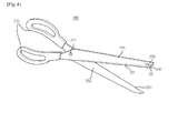
- FIG. 4 is a perspective view of a knife according to another embodiment of the present invention.
- the protrusion 130 is formed above the distal end of the body 120, with the insertion portion 132 formed in between.
- a motion such as peel-off of the skin of an object may be made with the knife.
- the knife is used with the body 120 tilted forward and backward more often than with the body 120 upright over the ground or an object in a kitchen or an office.
- the object may not be cut accurately and particularly, the skin of the object may be peeled off less efficiently due to the thickness of the body 120.
- the protrusion 130 since the protrusion 130 is likely to impair reverse use of the knife, the distal end of the body 120 and the protrusion 130 may be mutually stepped forward or backward in order to overcome this problem.
- a step 135 may be formed to protrude forward at a position at which a part of the body 120 having the upper blade 131 is connected to the protrusion 130
- the upper end of the upper blade 131 roughly corresponds to a forward corner of the protrusion 130 in the example of FIG. 4 .
- the insertion portion 132 is roughly square, the inner blade 133 is formed at the other end of the insertion portion 132, and thus the step 135 is formed at a lower end portion of the inner blade 133, the step 135 may be formed right under the protrusion 130. Therefore, the present invention is not limited to the specific embodiment and thus it is to be understood that the various embodiments of FIG. 2 are applicable to shapes apparent from the present invention. Thus, the user may use the knife easily when tilting the knife forward on an object.
- FIG. 5 is a view illustrating a use state of a knife having a protection means according to the present invention.
- the user may use the upper blade 131. Specifically, if the user needs to continuously cut a thin skin of an object such as a fish, the user may stab the distal end of the body 120 into a specific part of the object and cut the skin, while inserting the skin into the insertion portion 132.
- the user presses the knife forward on the object, holding the handle 110 and cuts the object with the upper blade 131, while a specific part of the protrusion 130 supports the object.
- the skin of the object can be peeled off efficiently without interruptions in the middle of a cutting motion by means of the protrusion 130, the insertion portion 132, and the upper blade 131. Consequently, the risk of safety incidents is remarkably reduced.
- the operation mechanism of the protrusion 130, the insertion 132, and the upper blade 131 according to the present invention is applicable to various (single-edged) cutting devices having only a bottom blade as well as the knife.
- FIG. 6 is a perspective view illustrating a pair of scissors having a protection means according to the present invention.
- a pair of scissors 200 cut an object placed between two members, that is, a first body 220 and a second body 250 through leverage movement between the first and second bodies 220 and 250.
- Each of the first and second bodies 220 and 250 is grabbed by means of a handle 210. As the handles 210 approach or move away from each other, edges of the first and second bodies 220 and 250 cut an object by contacting or departing from each other upon a hinge 211.
- a facing edge of the first or second body 220 or 250 does not need to be shaped into a blade. Rather, it is sufficient to form a sharp edge only in a part in which a lower edge of the first body 220 and an upper edge of the second body 250 meet. However, it is preferred that an edge of at least one body has a wedge-shaped side section like a knife blade in order to ensure the efficiency of a cutting motion.
- the scissors 200 need to be used, inserted in a specific part and the first body 220 and/or the second body 250 is tapered toward one end of the scissors 200.
- a protrusion 230 may protrude forward, spaced upward from a distal end of the first body 220 and an insertion portion 232 may be formed between the protrusion 230 and the distal end of the body 220.
- the protrusion 230 and the insertion portion 232 may be formed in same shapes as their counter parts of the afore-described knife and thus will not be described herein to avoid redundancy.
- the protrusion 230 protrudes in one direction further than at least the distal end of the first body 220 in which an upper blade 231 is formed.
- the protrusion 230 may protrude further than the distal ends of the first and second bodies 220 and 250 in the state where the first and second bodies 220 and 250 are brought into contact and overlapped, when seen from the front.
- the protrusion 230, the insertion portion 232, and the upper blade 231 are also applicable to the second body 250.
- the protrusions 130 and 230 may function as protection means and guides. Accordingly, the protrusions 130 and 230 may be formed of a softer material than the bodies 120 and 220. Or a part of the protrusions 130 and 230 may be formed of the softer material.
- the structure of the scissors 200 facilitates fine motions such as opening an envelope or removing a cover, with increased safety.
- the knife and scissors having a protection means according to the present invention obviate the need for reverse use by means of a protrusion, an insertion portion, and an upper blade formed at the bottom of the insertion portion. Therefore, a motion such as fine removal of the skin or film of an object can be made at one time, thereby remarkably increasing use accuracy and convenience.
Landscapes
- Life Sciences & Earth Sciences (AREA)
- Engineering & Computer Science (AREA)
- Forests & Forestry (AREA)
- Mechanical Engineering (AREA)
- Wood Science & Technology (AREA)
- Zoology (AREA)
- Food Science & Technology (AREA)
- Knives (AREA)
- Scissors And Nippers (AREA)
Applications Claiming Priority (2)
| Application Number | Priority Date | Filing Date | Title |
|---|---|---|---|
| KR1020120120026A KR101390372B1 (ko) | 2012-10-26 | 2012-10-26 | 보호수단을 구비한 칼 및 가위 |
| PCT/KR2013/009572 WO2014065629A1 (fr) | 2012-10-26 | 2013-10-25 | Couteau et ciseaux dotés d'un moyen de protection |
Publications (2)
| Publication Number | Publication Date |
|---|---|
| EP2913166A1 true EP2913166A1 (fr) | 2015-09-02 |
| EP2913166A4 EP2913166A4 (fr) | 2016-07-27 |
Family
ID=50544927
Family Applications (1)
| Application Number | Title | Priority Date | Filing Date |
|---|---|---|---|
| EP13848971.1A Withdrawn EP2913166A4 (fr) | 2012-10-26 | 2013-10-25 | Couteau et ciseaux dotés d'un moyen de protection |
Country Status (6)
| Country | Link |
|---|---|
| US (1) | US9744681B2 (fr) |
| EP (1) | EP2913166A4 (fr) |
| JP (1) | JP5960924B2 (fr) |
| KR (1) | KR101390372B1 (fr) |
| CN (1) | CN104884213B (fr) |
| WO (1) | WO2014065629A1 (fr) |
Cited By (1)
| Publication number | Priority date | Publication date | Assignee | Title |
|---|---|---|---|---|
| GB2575768A (en) * | 2018-03-23 | 2020-01-29 | Djamel Guechdi Ahmed | Knife |
Families Citing this family (5)
| Publication number | Priority date | Publication date | Assignee | Title |
|---|---|---|---|---|
| KR101390372B1 (ko) * | 2012-10-26 | 2014-04-29 | 홍기영 | 보호수단을 구비한 칼 및 가위 |
| KR101905043B1 (ko) * | 2015-11-13 | 2018-10-08 | 홍기영 | 날의 선택적 사용이 가능한 가위 |
| KR20170072456A (ko) * | 2015-12-17 | 2017-06-27 | 홍기영 | 파지가 용이한 위생 칼 |
| KR101908900B1 (ko) * | 2018-06-29 | 2018-12-10 | 박재익 | 다용도 가위 |
| US11231250B1 (en) * | 2019-02-18 | 2022-01-25 | Jodi Sheryl Fisher | Handheld defense and deterrence device |
Family Cites Families (28)
| Publication number | Priority date | Publication date | Assignee | Title |
|---|---|---|---|---|
| US1988386A (en) * | 1933-05-18 | 1935-01-15 | Ole N Komperud | Knife |
| US2126080A (en) * | 1937-02-20 | 1938-08-09 | Jacob P Backer | Paring knife |
| US3839788A (en) * | 1971-07-06 | 1974-10-08 | C Addis | Eviscerating and skinning knife |
| US3918158A (en) * | 1974-06-13 | 1975-11-11 | Joseph Z Debski | Specialty knife |
| JPS5374351U (fr) * | 1976-11-18 | 1978-06-21 | ||
| US4198751A (en) * | 1978-12-11 | 1980-04-22 | Egbert Lawrence E | Skinning knife |
| JPS5822022U (ja) * | 1981-07-24 | 1983-02-10 | 島 顕侑 | ケ−ブルの加工工具 |
| JPS6015267U (ja) * | 1983-07-12 | 1985-02-01 | 伊藤 益太 | 包丁 |
| JPS60101043U (ja) * | 1983-12-15 | 1985-07-10 | 炭竃 利夫 | 調理用ナイフ |
| US4569103A (en) * | 1984-09-14 | 1986-02-11 | David Taurinskas | Crab leg knife |
| JPS6337166U (fr) * | 1986-08-27 | 1988-03-10 | ||
| US4753009A (en) * | 1987-03-09 | 1988-06-28 | Haga Mary I | Multi-function sewing implement |
| US5613904A (en) * | 1995-09-25 | 1997-03-25 | Lasalle Product Development, Inc. | Utensil for opening the shells of crustaceans |
| US5784787A (en) * | 1997-01-03 | 1998-07-28 | Jensen; Alan | Sheet metal penetrating tool |
| DE29920823U1 (de) * | 1999-11-27 | 2000-07-27 | Macek, Leopold, 97717 Sulzthal | Aufbruchmesser mit 3 Funktionen speziell für Jäger, Förster oder Metzger |
| KR200384835Y1 (ko) * | 2005-03-02 | 2005-05-19 | 박현우 | 섬세한 작업이 가능한 안전칼 |
| US7121939B1 (en) * | 2006-03-20 | 2006-10-17 | Anthony Crosby Quaglino | Utensil configured for opening shellfish shell and method for providing same |
| JP4719887B2 (ja) * | 2006-06-09 | 2011-07-06 | 国立大学法人 岡山大学 | ストーマ開孔具 |
| US20080178474A1 (en) * | 2007-01-31 | 2008-07-31 | Spencer John E | Dropped point push hook skinner knife blade |
| GB2473242A (en) * | 2009-09-07 | 2011-03-09 | John William Cornock | Meat cleaver |
| CN201702784U (zh) * | 2010-03-18 | 2011-01-12 | 吴诗平 | 一种可装药品的菜刀 |
| US9119644B2 (en) * | 2010-08-21 | 2015-09-01 | New York Society For The Ruptured And Crippled Maintaining The Hospital For Special Surgery | Instruments for use in femoroacetabular impingement procedures |
| KR20110004046U (ko) | 2010-10-11 | 2011-04-25 | 최찬두 | 4가지 기능을 부가한 주방용 칼. |
| JP3165846U (ja) * | 2010-11-05 | 2011-02-10 | 豊春 前田 | 包丁及びナイフ |
| DE102011007909B4 (de) * | 2011-04-21 | 2013-05-29 | Angelzubehör MaNe UG (haftungsbeschränkt) | Nach Art eines Taschenmessers ausgeführtes zum Betäuben und Ausweiden von Fischen geeignetes Mehrzweckgerät |
| JP2014018348A (ja) * | 2012-07-17 | 2014-02-03 | Dr Nakamats Com | 殺傷犯罪防止刃物 |
| KR101390372B1 (ko) * | 2012-10-26 | 2014-04-29 | 홍기영 | 보호수단을 구비한 칼 및 가위 |
| CN203210397U (zh) * | 2013-04-09 | 2013-09-25 | 陈琏妃 | 一种牛油刀 |
-
2012
- 2012-10-26 KR KR1020120120026A patent/KR101390372B1/ko active Active
-
2013
- 2013-10-25 JP JP2015539504A patent/JP5960924B2/ja not_active Expired - Fee Related
- 2013-10-25 US US14/438,789 patent/US9744681B2/en not_active Expired - Fee Related
- 2013-10-25 EP EP13848971.1A patent/EP2913166A4/fr not_active Withdrawn
- 2013-10-25 WO PCT/KR2013/009572 patent/WO2014065629A1/fr not_active Ceased
- 2013-10-25 CN CN201380068058.3A patent/CN104884213B/zh not_active Expired - Fee Related
Cited By (2)
| Publication number | Priority date | Publication date | Assignee | Title |
|---|---|---|---|---|
| GB2575768A (en) * | 2018-03-23 | 2020-01-29 | Djamel Guechdi Ahmed | Knife |
| GB2575768B (en) * | 2018-03-23 | 2023-02-08 | Djamel Guechdi Ahmed | Knife |
Also Published As
| Publication number | Publication date |
|---|---|
| CN104884213B (zh) | 2017-07-04 |
| JP5960924B2 (ja) | 2016-08-02 |
| KR101390372B1 (ko) | 2014-04-29 |
| WO2014065629A1 (fr) | 2014-05-01 |
| US9744681B2 (en) | 2017-08-29 |
| US20150283717A1 (en) | 2015-10-08 |
| JP2015534848A (ja) | 2015-12-07 |
| EP2913166A4 (fr) | 2016-07-27 |
| CN104884213A (zh) | 2015-09-02 |
Similar Documents
| Publication | Publication Date | Title |
|---|---|---|
| US9744681B2 (en) | Knife and scissors provided with protection means | |
| US10377619B2 (en) | Bag cutter and piercer | |
| US9132559B2 (en) | Cutlery having improved gripping ergonomics | |
| US8556915B2 (en) | Skin removal instrument | |
| US8992289B2 (en) | Knife with hook for skinning and methods of using the same | |
| US11708256B2 (en) | Bag cutter and piercer | |
| US20120240411A1 (en) | Knife Safety Apparatus | |
| US20060288582A1 (en) | Corn scraper | |
| US20170325615A1 (en) | Kitchen utensil | |
| JP3172439U (ja) | 野菜を押し切りする手動刃物 | |
| CA3075369C (fr) | Coupe-sacs et dispositif de percage de sacs | |
| KR20230099266A (ko) | 가위 | |
| JP3207312U (ja) | 凸状円弧刃ナイフ | |
| JP2017070274A (ja) | 魚の下ごしらえ道具 | |
| CN101973039A (zh) | 安全防割刀具 | |
| CN209137111U (zh) | 一种急诊科用绷带剪切装置 | |
| CN209172438U (zh) | 一种一次性弧形剥离刀片 | |
| JP6016442B2 (ja) | 鱗取り具 | |
| KR101389161B1 (ko) | 감자칼용 커터의 제조방법 | |
| JP2004167089A (ja) | 指保護具 | |
| KR20190056101A (ko) | 주방용 가위 | |
| CN107363867A (zh) | 一种菜刀 | |
| JPH0852063A (ja) | 果実の皮切り具 | |
| JP2000325244A (ja) | とうふのパックを切り開くカッター | |
| MX2009008590A (es) | Peladora manual de nopal. |
Legal Events
| Date | Code | Title | Description |
|---|---|---|---|
| PUAI | Public reference made under article 153(3) epc to a published international application that has entered the european phase |
Free format text: ORIGINAL CODE: 0009012 |
|
| 17P | Request for examination filed |
Effective date: 20150522 |
|
| AK | Designated contracting states |
Kind code of ref document: A1 Designated state(s): AL AT BE BG CH CY CZ DE DK EE ES FI FR GB GR HR HU IE IS IT LI LT LU LV MC MK MT NL NO PL PT RO RS SE SI SK SM TR |
|
| AX | Request for extension of the european patent |
Extension state: BA ME |
|
| DAX | Request for extension of the european patent (deleted) | ||
| RA4 | Supplementary search report drawn up and despatched (corrected) |
Effective date: 20160629 |
|
| RIC1 | Information provided on ipc code assigned before grant |
Ipc: B26B 9/00 20060101ALI20160623BHEP Ipc: B26B 11/00 20060101ALI20160623BHEP Ipc: B26B 29/04 20060101ALI20160623BHEP Ipc: B26B 29/02 20060101AFI20160623BHEP |
|
| 17Q | First examination report despatched |
Effective date: 20181024 |
|
| STAA | Information on the status of an ep patent application or granted ep patent |
Free format text: STATUS: THE APPLICATION IS DEEMED TO BE WITHDRAWN |
|
| 18D | Application deemed to be withdrawn |
Effective date: 20190305 |