EP2913252A2 - Solar battery mounting structure in a vehicle - Google Patents
Solar battery mounting structure in a vehicle Download PDFInfo
- Publication number
- EP2913252A2 EP2913252A2 EP15156072.9A EP15156072A EP2913252A2 EP 2913252 A2 EP2913252 A2 EP 2913252A2 EP 15156072 A EP15156072 A EP 15156072A EP 2913252 A2 EP2913252 A2 EP 2913252A2
- Authority
- EP
- European Patent Office
- Prior art keywords
- solar battery
- fixation
- vehicle body
- battery module
- body frame
- Prior art date
- Legal status (The legal status is an assumption and is not a legal conclusion. Google has not performed a legal analysis and makes no representation as to the accuracy of the status listed.)
- Granted
Links
Images


Classifications
-
- B—PERFORMING OPERATIONS; TRANSPORTING
- B62—LAND VEHICLES FOR TRAVELLING OTHERWISE THAN ON RAILS
- B62D—MOTOR VEHICLES; TRAILERS
- B62D25/00—Superstructure or monocoque structure sub-units; Parts or details thereof not otherwise provided for
- B62D25/06—Fixed roofs
-
- B—PERFORMING OPERATIONS; TRANSPORTING
- B60—VEHICLES IN GENERAL
- B60K—ARRANGEMENT OR MOUNTING OF PROPULSION UNITS OR OF TRANSMISSIONS IN VEHICLES; ARRANGEMENT OR MOUNTING OF PLURAL DIVERSE PRIME-MOVERS IN VEHICLES; AUXILIARY DRIVES FOR VEHICLES; INSTRUMENTATION OR DASHBOARDS FOR VEHICLES; ARRANGEMENTS IN CONNECTION WITH COOLING, AIR INTAKE, GAS EXHAUST OR FUEL SUPPLY OF PROPULSION UNITS IN VEHICLES
- B60K16/00—Arrangements in connection with power supply of propulsion units in vehicles from forces of nature, e.g. sun or wind
-
- B—PERFORMING OPERATIONS; TRANSPORTING
- B62—LAND VEHICLES FOR TRAVELLING OTHERWISE THAN ON RAILS
- B62D—MOTOR VEHICLES; TRAILERS
- B62D29/00—Superstructures, understructures, or sub-units thereof, characterised by the material thereof
- B62D29/04—Superstructures, understructures, or sub-units thereof, characterised by the material thereof predominantly of synthetic material
- B62D29/043—Superstructures
-
- H—ELECTRICITY
- H02—GENERATION; CONVERSION OR DISTRIBUTION OF ELECTRIC POWER
- H02S—GENERATION OF ELECTRIC POWER BY CONVERSION OF INFRARED RADIATION, VISIBLE LIGHT OR ULTRAVIOLET LIGHT, e.g. USING PHOTOVOLTAIC [PV] MODULES
- H02S10/00—PV power plants; Combinations of PV energy systems with other systems for the generation of electric power
- H02S10/10—PV power plants; Combinations of PV energy systems with other systems for the generation of electric power including a supplementary source of electric power, e.g. hybrid diesel-PV energy systems
-
- H—ELECTRICITY
- H02—GENERATION; CONVERSION OR DISTRIBUTION OF ELECTRIC POWER
- H02S—GENERATION OF ELECTRIC POWER BY CONVERSION OF INFRARED RADIATION, VISIBLE LIGHT OR ULTRAVIOLET LIGHT, e.g. USING PHOTOVOLTAIC [PV] MODULES
- H02S20/00—Supporting structures for PV modules
- H02S20/30—Supporting structures being movable or adjustable, e.g. for angle adjustment
-
- H—ELECTRICITY
- H10—SEMICONDUCTOR DEVICES; ELECTRIC SOLID-STATE DEVICES NOT OTHERWISE PROVIDED FOR
- H10F—INORGANIC SEMICONDUCTOR DEVICES SENSITIVE TO INFRARED RADIATION, LIGHT, ELECTROMAGNETIC RADIATION OF SHORTER WAVELENGTH OR CORPUSCULAR RADIATION
- H10F10/00—Individual photovoltaic cells, e.g. solar cells
-
- H—ELECTRICITY
- H10—SEMICONDUCTOR DEVICES; ELECTRIC SOLID-STATE DEVICES NOT OTHERWISE PROVIDED FOR
- H10F—INORGANIC SEMICONDUCTOR DEVICES SENSITIVE TO INFRARED RADIATION, LIGHT, ELECTROMAGNETIC RADIATION OF SHORTER WAVELENGTH OR CORPUSCULAR RADIATION
- H10F19/00—Integrated devices, or assemblies of multiple devices, comprising at least one photovoltaic cell covered by group H10F10/00, e.g. photovoltaic modules
- H10F19/80—Encapsulations or containers for integrated devices, or assemblies of multiple devices, having photovoltaic cells
-
- B—PERFORMING OPERATIONS; TRANSPORTING
- B60—VEHICLES IN GENERAL
- B60K—ARRANGEMENT OR MOUNTING OF PROPULSION UNITS OR OF TRANSMISSIONS IN VEHICLES; ARRANGEMENT OR MOUNTING OF PLURAL DIVERSE PRIME-MOVERS IN VEHICLES; AUXILIARY DRIVES FOR VEHICLES; INSTRUMENTATION OR DASHBOARDS FOR VEHICLES; ARRANGEMENTS IN CONNECTION WITH COOLING, AIR INTAKE, GAS EXHAUST OR FUEL SUPPLY OF PROPULSION UNITS IN VEHICLES
- B60K16/00—Arrangements in connection with power supply of propulsion units in vehicles from forces of nature, e.g. sun or wind
- B60K2016/003—Arrangements in connection with power supply of propulsion units in vehicles from forces of nature, e.g. sun or wind solar power driven
-
- B—PERFORMING OPERATIONS; TRANSPORTING
- B62—LAND VEHICLES FOR TRAVELLING OTHERWISE THAN ON RAILS
- B62D—MOTOR VEHICLES; TRAILERS
- B62D27/00—Connections between superstructure or understructure sub-units
- B62D27/02—Connections between superstructure or understructure sub-units rigid
- B62D27/026—Connections by glue bonding
-
- Y—GENERAL TAGGING OF NEW TECHNOLOGICAL DEVELOPMENTS; GENERAL TAGGING OF CROSS-SECTIONAL TECHNOLOGIES SPANNING OVER SEVERAL SECTIONS OF THE IPC; TECHNICAL SUBJECTS COVERED BY FORMER USPC CROSS-REFERENCE ART COLLECTIONS [XRACs] AND DIGESTS
- Y02—TECHNOLOGIES OR APPLICATIONS FOR MITIGATION OR ADAPTATION AGAINST CLIMATE CHANGE
- Y02E—REDUCTION OF GREENHOUSE GAS [GHG] EMISSIONS, RELATED TO ENERGY GENERATION, TRANSMISSION OR DISTRIBUTION
- Y02E10/00—Energy generation through renewable energy sources
- Y02E10/50—Photovoltaic [PV] energy
-
- Y—GENERAL TAGGING OF NEW TECHNOLOGICAL DEVELOPMENTS; GENERAL TAGGING OF CROSS-SECTIONAL TECHNOLOGIES SPANNING OVER SEVERAL SECTIONS OF THE IPC; TECHNICAL SUBJECTS COVERED BY FORMER USPC CROSS-REFERENCE ART COLLECTIONS [XRACs] AND DIGESTS
- Y02—TECHNOLOGIES OR APPLICATIONS FOR MITIGATION OR ADAPTATION AGAINST CLIMATE CHANGE
- Y02T—CLIMATE CHANGE MITIGATION TECHNOLOGIES RELATED TO TRANSPORTATION
- Y02T10/00—Road transport of goods or passengers
- Y02T10/80—Technologies aiming to reduce greenhouse gasses emissions common to all road transportation technologies
- Y02T10/90—Energy harvesting concepts as power supply for auxiliaries' energy consumption, e.g. photovoltaic sun-roof
Definitions
- the present invention relates to a solar battery mounting structure including a solar battery module fixed to a vehicle body frame member.
- Japanese Unexamined Patent Application Publication No. 2010-137809 is known as Technical Literature relevant to a vehicle body mounting structure of a solar battery cell.
- a vehicle upper portion structure including a solar battery cell which is disposed in an upper portion of a front window of a vehicle and/or an upper portion of a rear window of the vehicle, and receives light from both a vehicle exterior side and a vehicle interior side and converts the light into electrical energy, is disclosed.
- Japanese Unexamined Utility Model Registration Application Publication No. 3-117854 Japanese Unexamined Patent Application Publication No. 2002-043608 , Japanese Unexamined Patent Application Publication No. 2000-352175 , and Japanese Unexamined Patent Application Publication No. 2000-068539 are examples of the related art.
- the solar battery cell may be used in a configuration of the solar battery module including a light transmissive plate member such as glass on which solar light is incident from an upper surface, and a sealing material layer which is disposed on a lower surface side of the light transmissive plate member and includes the solar battery cell therein.
- a solar battery module is disposed in an upper surface of a vehicle body, the solar battery module is usually mounted on (fixed to) the vehicle body due to adhesion between the light transmissive plate member such as glass and the vehicle body frame member (for example, a roof side rail).
- a solar battery mounting structure including a solar battery module which is disposed in an upper surface of a vehicle body and is fixed to a vehicle body frame member, in which the solar battery module includes a light transmissive plate member which is arranged along the upper surface of the vehicle body, an adhesive portion by which a lower surface of a side end portion of the light transmissive plate member is adhered to an adhesive surface of the vehicle body frame member, and a fixation portion which is fixed to a lower surface of the light transmissive plate member through a sealing material layer, and is fixed to a fixation surface of the vehicle body frame member facing the lower surface, a protrusion portion which is in contact with the lower surface of the light transmissive plate member through the sealing material layer is formed in the fixation portion, and in the vehicle body frame member, a step portion is formed between the adhesive surface and the fixation surface, and the fixation surface is separated from the lower surface of the light transmissive plate member compared to the adhesive
- the light transmissive plate member is adhered to the adhesive surface of the vehicle body frame member, and further, the fixation portion is fixed to the fixation surface of the vehicle body frame member, and thus it is possible to increase a fixation point (a connection point) between the vehicle body frame member and the solar battery module, and it is possible to ensure impact resistance of the solar battery module compared to the related art in which only the light transmissive plate member is fixed to the vehicle body frame member.
- the protrusion portion which is in contact with the lower surface of the light transmissive plate member through the sealing material layer is formed in the fixation portion, and thus, for example, the fixation portion sinks in the sealing material layer at the time of manufacturing the solar battery module, and it is possible to avoid displacement in a position of the fixation portion.
- the step portion is formed between the adhesive surface and the fixation surface, and the fixation surface is separated from the lower surface of the light transmissive plate member compared to the adhesive surface, and thus it is possible to ensure a space for disposing the fixation portion in the sealing material layer compared to a case where the step portion is not included.
- the solar battery mounting structure it is possible to ensure impact resistance of the solar battery module by fixing a portion other than the light transmissive plate member to the vehicle body frame member, and thus it is advantageous for a reduction in a thickness of the light transmissive plate member. This contributes to a reduction in weight of the vehicle on which the solar battery module is mounted.
- the vehicle body frame member may include a body bracket protruding toward the fixation portion, and the fixation surface may be formed in the body bracket.
- the body bracket in the vehicle body frame member, it is possible to form the fixation surface in a suitable position in the vehicle body having various shapes, and thus general versatility is improved.
- the fixation portion may include a resin member in which a nut is embedded, the fixation surface has a bolt hole opened therein, and the fixation portion may be fixed to the fixation surface by a bolt may be screwed into the nut through the bolt hole.
- the nut and the bolt of the resin member are screwed in a state where a shaft portion of the bolt is inserted into the bolt hole in the fixation surface of the vehicle body frame member, and thus it is possible to fix the fixation portion of the solar battery module to the fixation surface of the vehicle body frame member in a comparatively easy configuration.
- the step portion is formed between the adhesive surface and the fixation surface in the vehicle body frame member, and thus it is possible to ensure an arrangement space of the nut by the step, and it is possible to obtain necessary strength by sufficiently taking a length for screwing the nut and the bolt.
- a plurality of positioning pins for positioning the fixation portion at the time of manufacturing the solar battery module may be disposed in the lower surface of the light transmissive plate member.
- the fixation portion is positioned with respect to the lower surface of the light transmissive plate member by the plurality of positioning pins, and thus position displacement of the fixation portion is avoided at the time of forming the sealing material layer in manufacturing of the solar battery module. Accordingly, in the solar battery mounting structure, it is possible to suppress the position displacement of the fixation portion, and thus it is possible to improve stability of fixation between the solar battery module and the vehicle body frame member.
- a back sheet which is disposed on a side of the sealing material layer opposite to the light transmissive plate member may be further included.
- the solar battery mounting structure it is possible to improve strength of the sealing material layer by the back sheet which is disposed on the side of the sealing material layer opposite to the light transmissive plate member. This contributes to an improvement in durability of the solar battery module.
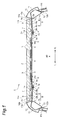
- a solar battery mounting structure is a structure for mounting a solar battery module 1 on a vehicle body.
- a type of the vehicle body including the solar battery module 1 mounted thereon is not particularly limited, and may be a vehicle body of a passenger vehicle, may be a vehicle body of a shared vehicle such as a bus, or may be a vehicle body of a freight vehicle such as a van or a truck.
- an upper direction UP, a left direction L, and a right direction R of the vehicle body are illustrated by arrows.
- the solar battery module 1 is fixed to a vehicle body frame member B configuring the vehicle body.
- the vehicle body frame member B includes a roof side rail, a roof panel, a roof panel reinforcement, and the like, which constitute the vehicle body.
- the vehicle body frame member B to which the solar battery module 1 is fixed may include a front body pillar, a center body pillar, a side outer panel, and the like.
- the solar battery module 1 is disposed in an upper surface of the vehicle body, and may configure a part of a roof of the vehicle body. Specifically, the solar battery module 1 is fixed to a pair of right and left roof side rails Rs configuring the vehicle body frame member B.
- the upper surface of the vehicle body for example, is an upper surface of a roof panel (not illustrated) supported by the roof side rail Rs.
- the upper surface of the roof panel for example, is positioned between upper ends of the pair of roof side rails Rs.
- the roof side rail Rs is configured by a roof side rail reinforcement 11 arranged on a vehicle exterior side, and a roof side inner rail 12.
- An upper end portion 12a of the roof side inner rail 12 is overlapped with an upper end portion 11 a of the roof side rail reinforcement 11.
- a lower end portion 11b of the roof side rail reinforcement 11 is overlapped with a lower end portion 12b of the roof side inner rail 12.
- a vertical cross section of the roof side rail reinforcement 11 and the roof side inner rail 12 forms a closed cross section.
- the upper end portion 11 a side of the roof side rail reinforcement 11 extends toward an inner side (a cabin side) from the upper end portion 12a of the roof side inner rail 12.
- a side outer panel 13 is arranged outside the roof side rail reinforcement 11.
- An upper end portion 13a of the side outer panel 13 is overlapped with the upper end portion 11 a of the roof side rail reinforcement 11. That is, the upper end portion 11a of the roof side rail reinforcement 11 is interposed between the upper end portion 13 a of the side outer panel 13 and the upper end portion 12a of the roof side inner rail 12 in a vertical direction.
- the upper end portion 11a of the roof side rail reinforcement 11 protrudes toward the solar battery module 1 from the upper end portion 13a of the side outer panel 13 and the upper end portion 12a of the roof side inner rail 12.
- the solar battery module 1 is fixed to an upper surface of the upper end portion 11 a.
- the solar battery module 1 includes plate-like glass 2 which is able to transmit light, a solar battery cell 3, a sealing material layer 4, a fixation portion 5, a back sheet 6, and a sealing member 7.
- the glass 2 is arranged along an upper surface of the vehicle body, and is a rectangular light transmissive plate member having light permeability which transmits solar light.
- the glass 2 is a plate member having an upper surface (a front surface) 2a on which the solar light is incident.
- the glass 2 has a suitable thickness for ensuring strength of the solar battery module 1.
- the glass 2 may be in the shape of a flat plate shape, or may be in the shape of a curved plate. In this embodiment, the glass 2 is in the shape of a flat plate, and a thickness direction of the glass 2 is identical to the vertical direction.
- a plate member formed of a light permeability resin such as acryl, polyethylene terephthalate (PET), polyethylene naphthalate (PEN), and polycarbonate may be used.
- the glass 2 is arranged over the pair of right and left roof side rails Rs.
- a lower surface (a back surface) 2b of the glass 2 is adhered to each of the pair of roof side rails Rs.
- the glass 2 is fixed to the roof side rail Rs by a so-called direct grading method, and an adhesive portion S is disposed between the glass 2 and the roof side rail Rs.
- the adhesive portion S is fixed by adhesion between the pair of roof side rails Rs and the glass 2.
- the adhesive portion S for example, is formed of a urethane resin.
- the adhesive portion S is not limited to the adhesive portion formed of the urethane resin, and may be formed of other known adhesive agents.
- the adhesive portion S is formed between each lower surface 2b of a pair of side end portions 2c and 2d of the glass 2, and each adhesive surface F 1 of the pair of roof side rails Rs.
- the pair of side end portions 2c and 2d in the glass 2 are end portions of the vehicle body in a width direction which face each other in a horizontal direction.
- the adhesive surface F 1 is an upper surface of the roof side rail Rs (the roof side rail reinforcement 11) facing the lower surface 2b of the pair of side end portions 2c and 2d in the vertical direction.
- the pair of roof side rails Rs includes each of the adhesive surfaces F 1 .
- the lower surface 2b of the pair of side end portions 2c and 2d of the glass 2 is adhered to the adhesive surface F 1 of the pair of roof side rails Rs.
- the glass 2 not only the lower surface 2b of the pair of side end portions 2c and 2d which face each other in the horizontal direction, but also the lower surface 2b of the pair of side end portions which face each other in a front-back direction is adhered to the vehicle body frame member B (for example, the roof panel reinforcement).
- the sealing material layer 4 including the solar battery cell 3 therein is disposed on a center side of the lower surface 2b of the glass 2, the sealing material layer 4 including the solar battery cell 3 therein is disposed.
- the sealing material layer 4 is disposed between a pair of adhesive portions S.
- the solar battery cell 3 is an instrument converting light energy into direct power by using a photovoltaic effect, and for example, a silicon-based solar battery cell 3 is used.
- a silicon-based solar battery cell 3 any one of a single crystalline silicon-based solar battery cell, a polycrystalline silicon-based solar battery cell, and an amorphous silicon-based solar battery cell may be used.
- the single crystalline silicon-based solar battery cell has excellent photoelectric conversion efficiency, and the amorphous silicon-based solar battery cell has smaller efficiency degradation due to an increase in temperature.
- a known solar battery cell is able to be adopted, and a solar battery cell of a compound such as GaAs (gallium arsenide) or an organic solar battery cell, and other solar
- the sealing material layer 4 is a layer protecting the solar battery cell 3 from being degraded due to moisture, oxygen, or the like by sealing the solar battery cell 3.
- the sealing material layer 4 is formed of a light permeability resin.
- EVA Ethylene Vinyl Acetate
- PVB Poly Vinyl Butyral
- an ion crosslinked polyolefin-based resin, and the like are able to be adopted.
- Fig. 2 is a bottom view illustrating the solar battery module 1.
- a front direction Fr of the vehicle body and a back direction Rr of the vehicle body are illustrated by arrows in addition to the upper direction UP of the vehicle body, the left direction L of the vehicle body, and the right direction R of the vehicle body.
- a plurality of solar battery cells 3 are arranged on the same plane inside the sealing material layer 4.
- a total of 16 (4 sheets ⁇ 4 rows) solar battery cells 3 are arranged at predetermined intervals.
- the number of solar battery cells 3 or an arrangement thereof is not limited to the number of solar battery cells 3 or the arrangement thereof illustrated in Fig. 1 and Fig. 2 .
- fixation portion 5 On a side of the sealing material layer 4 opposite to the glass 2 (a lower surface side), a pair of right and left fixation portions 5 are disposed.
- the fixation portion 5 is fixed to the lower surface 2b of the glass 2 through the sealing material layer 4.
- the fixation portion 5 is a portion which is fixed to the vehicle body frame member B. Fixation of the fixation portion 5 will be described later in detail.
- the back sheet 6 is arranged between the pair of right and left fixation portions 5.
- the back sheet 6, for example, is a multilayered resin film, and is disposed to cover the sealing material layer 4.
- an end portion 6a of the back sheet 6 in the horizontal direction is arranged to be overlapped on the fixation portion 5.
- the back sheet 6 prevents moisture, oxygen, or the like from invading (infiltration) the sealing material layer 4.
- a sealing member such as a butyl tape may be disposed to cover a gap between the back sheet 6 and the fixation portion 5.
- the back sheet 6 As a material of the back sheet 6, for example a fluoride resin such as polyvinylidene fluoride (PVF), and an ester resin such as polyethylene terephthalate (PET) are able to be adopted, and as necessary, a metallic film is able to be interposed between layers.
- the back sheet 6 improves strength of the sealing material layer 4, and contributes to an improvement in durability of the solar battery module 1.
- the sealing member 7 is a member for preventing moisture, oxygen, or the like from invading (infiltrating) the sealing material layer 4.
- the sealing member 7 is not particularly limited insofar as the sealing material layer 4 is able to be protected by a configuration of the sealing member 7.
- fixation between the fixation portion 5 and the vehicle body frame member B will be described.
- the fixation portion 5 and the vehicle body frame member B are mechanically fixed to each other by using a nut 9 and a bolt 10.
- a fixing method of the fixation portion 5 and the vehicle body frame member B is not limited to the fixing method using the nut 9 and the bolt 10. Other fixing methods will be described later.
- the fixation portion 5 is a plate-like resin member which is disposed to cover right and left end portions of the sealing material layer 4 on the side of the sealing material layer 4 opposite to the glass 2.
- the fixation portion 5 is in the shape of a rectangle of which a longitudinal direction is the front-back direction of the vehicle body.
- a material of the fixation portion 5 a polyamide, polypropylene, and polyethylene terephthalate are able to be adopted. Fibers or fillers may be included in these resins.
- the fixation portion 5 also functions as a sealing member which inhibits moisture, oxygen, or the like from invading (infiltrating) the sealing material layer 4.
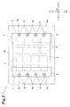
- Fig. 3(a) is an enlarged cross-sectional view of the solar battery module 1 of Fig. 1 .
- Fig. 3(b) is an enlarged bottom view of the solar battery module 1 of Fig. 2 .
- the fixation portion 5 is molded in a state where the nut 9 is inserted, and includes four thick portions 5 a in which the nut 9 is embedded.
- the four thick portions 5a are formed at predetermined intervals by being arranged in the front-back direction of the vehicle body.
- the thick portion 5a is formed along an outer side (the sealing member 7 side) of the fixation portion 5 in the horizontal direction.
- the thick portion 5a is a portion in which a resin is formed to be thick in order to maintain the nut 9 with sufficient strength.
- a thickness of the fixation portion 5 may be approximately uniform but for the thick portion 5a.
- a known nut is able to be adopted, and for example, an insert nut in which concavities and convexities are formed on an outer circumferential surface is able to be adopted.
- the nut 9 is embedded in the center of the thick portion 5 a such that a female screw portion is exposed when viewed from the bottom.
- the number of thick portions 5a and the number of nuts 9 are not limited to four, and may be one or more.
- the entire thickness of the fixation portion 5 may be identical to a thickness of the thick portion 5a.
- a size or an arrangement of the nut 9 is not limited to the size or the arrangement illustrated in the drawings.
- Fig. 4(a) is an enlarged cross-sectional view illustrating the solar battery module 1 fixed to the vehicle body frame member B.
- Fig. 4(a) is an enlarged bottom view illustrating the solar battery module 1 fixed to the vehicle body frame member B.
- the vehicle body frame member B includes a body bracket 8 which is fixed to the roof side rail Rs.
- the body bracket 8 for example, is an elongated metallic plate member extending in the front-back direction of the vehicle body along the fixation portion 5.
- the body bracket 8 is divided into a base end portion 8a, a tip end portion 8b, and a step portion 8c in the horizontal direction.
- the base end portion 8a is a portion which is fixed to the roof side rail Rs. Specifically, the base end portion 8a is welded to a back surface (a lower surface) of the adhesive surface F 1 of the roof side rail Rs.
- the tip end portion 8b is a portion in which a fixation surface F 2 fixed to the fixation portion 5 is formed.
- the fixation surface F 2 is a surface of the tip end portion 8b facing the lower surface 2b of the glass 2 in the vertical direction. Specifically, the fixation surface F 2 faces the fixation portion 5 in the vertical direction.
- fixation surface F 2 is separated from the lower surface 2b of the glass 2 in the vertical direction compared to the adhesive surface F 1 .
- a difference D between a height of the adhesive surface F 1 and a height of the fixation surface F 2 is illustrated.
- the difference D in the heights may be 3 mm to 10 mm.
- a bolt hole A into which the bolt 10 is inserted is formed to be opened.
- four bolt holes A corresponding to positions of the four nuts 9 are formed to be opened.
- the bolt 10 is screwed into the nut 9 of the fixation portion 5 through the bolt hole A, and thus the fixation portion 5 and the body bracket 8 are fixed to each other. That is, the fixation portion 5 of the solar battery module 1 and the fixation surface F 2 of the body bracket 8 of the vehicle body frame member B are mechanically fixed to each other by the bolt 10 and the nut 9.
- the bolt 10 a known bolt is able to be adopted.
- the bolt hole A is formed as a long hole extending in the horizontal direction.
- the bolt 10 is able to be screwed into the nut 9 through the bolt hole A even when slight displacement of the fixation portion 5 and the fixation surface F 2 occurs, and it is possible to make attachment work of the solar battery module 1 easy.
- an extending direction of the long hole in the bolt hole A is not limited to the horizontal direction, and for example, may be the front-back direction of the vehicle body.
- the step portion 8c is a portion which is formed between the base end portion 8a and the tip end portion 8b.
- the step portion 8c is formed to be lowered as approaching the fixation portion 5, and the tip end portion 8b is positioned below the base end portion 8a.
- the difference D between the adhesive surface F 1 and fixation surface F 2 in a height direction due to the step portion 8c is sufficiently ensured.
- the body bracket 8 may include four bolt holes A such that one body bracket 8 corresponds to all of the nuts 9, and one body bracket 8 may include only two bolt holes A.
- the body bracket 8 may include only one bolt hole A, and may be individually disposed on each nut 9.
- both the adhesive surface F 1 and the fixation surface F 2 may be formed in the roof side rail Rs.
- the step portion between the adhesive surface F 1 and the fixation surface F 2 is also formed.
- both the adhesive surface F 1 and the fixation surface F 2 may be formed in the body bracket 8.
- the fixation portion 5 includes a protrusion portion 14 protruding toward the lower surface 2b of the glass 2.
- Four protrusion portions 14, for example, are disposed in each thick portion 5a (in each nut 9).
- the four protrusion portions 14 are arranged to surround the nut 9.
- the four protrusion portions 14, for example, are disposed at equal intervals in a circumferential direction of the nut 9.
- the protrusion portion 14, for example, is formed into the shape of a column, and is in contact with the lower surface 2b of the glass 2 through the sealing material layer 4.
- the number of protrusion portions 14 is not limited to four, and may be one.
- an arrangement of the protrusion portion 14 is not limited to the arrangement described above.
- a shape of the protrusion portion 14 is not limited to a columnar shape, and may have any shape insofar as the protrusion portion 14 is able to be in contact with the lower surface 2b of the glass 2 through the sealing material layer 4.
- the protrusion portion 14, for example is able to be formed of a resin.
- the protrusion portion 14 is able to be integrally formed with the fixation portion 5 which is formed of a resin.
- the protrusion portion 14 may be formed of metal and other materials.
- the glass 2 is adhered to the adhesive surface F 1 of the vehicle body frame member B, and further, the fixation portion 5 is fixed to the fixation surface F 2 of the vehicle body frame member B, and thus it is possible to increase a fixation point (a connection point) between the solar battery module 1 and the vehicle body frame member B, and it is possible to ensure impact resistance of the solar battery module 1 compared to the related art in which only the glass 2 is fixed to the vehicle body frame member B.
- the step portion 8c is formed between the adhesive surface F 1 and the fixation surface F 2 of the vehicle body frame member B, and the fixation surface F 2 is separated from the lower surface 2b of the glass 2 compared to the adhesive surface F 1 , and thus it is possible to ensure a space for disposing the fixation portion 5 in the sealing material layer 4 compared to a case where the step portion 8c is not included. Accordingly, in the solar battery mounting structure, it is possible to ensure impact resistance of the solar battery module 1 by fixing a portion other than the glass 2 to the vehicle body frame member B, and thus it is advantageous for a reduction in a thickness of the glass 2. This contributes to a reduction in weight of the vehicle on which the solar battery module 1 is mounted.
- the protrusion portion 14 which is formed on the sealing material layer 4 side of the fixation portion 5 is in contact with the lower surface 2b of the glass 2, and thus for example, the fixation portion 5 sinks in the sealing material layer 4 at the time of manufacturing the solar battery module 1, and it is possible to avoid displacement from occurring in the position of the fixation portion 5.
- This improves reliability of a connection between the vehicle body frame member B and the solar battery module 1, and thus contributes to an improvement in impact resistance of the solar battery module 1.
- the body bracket in the vehicle body frame member B, it is possible to dispose the fixation surface F 2 in a suitable position in the vehicle body having various shapes, and thus general versatility is improved.
- the nut 9 and the bolt 10 in the fixation portion 5 are screwed in a state where a shaft portion of the bolt 10 is inserted into the bolt hole A in the fixation surface F 2 of the vehicle body frame member B, and thus it is possible to fix the fixation portion 5 of the solar battery module 1 to the fixation surface F 2 of the vehicle body frame member B in a comparatively easy configuration.
- the step portion 8c is formed between the adhesive surface F 1 and the fixation surface F 2 in the vehicle body frame member B, and thus it is possible to ensure an arrangement space of the nut 9 by the step, and it is possible to obtain necessary strength by sufficiently taking a length for screwing the nut 9 and the bolt 10.
- Fig. 5(a) is a cross-sectional view illustrating a step of arranging members in the manufacturing method of the solar battery module 1.
- Fig. 5(b) is a cross-sectional view illustrating a laminating step in the manufacturing method of the solar battery module 1.
- the solar battery module 1 is illustrated as being upside down from Fig. 1 .
- a second sealing material sheet 4B, the solar battery cell 3, a first sealing material sheet 4A, the fixation portion 5, and the back sheet 6 are laminated on the lower surface 2b of the glass 2 in this order.
- the sealing material sheets 4A and 4B are pressurized by the laminating step described later, and thus the sealing material layer 4 is formed.
- the fixation portion 5 is arranged such that the protrusion portion 14 is in contact with the lower surface 2b of the glass 2 through the first sealing material sheet 4A and the second sealing material sheet 4B. Furthermore, in the first sealing material sheet 4A and the second sealing material sheet 4B, a hole into which the protrusion portion 14 is inserted may be formed in advance. In addition, in the fixation portion 5, the nut 9 is embedded in advance.
- each glass 2 on which the various members are arranged in the step of arranging the members is input into a laminator, and is pressurized at a high temperature and a uniform pressure.
- the glass 2 is arranged on a heat plate H, and the various members on each of the glasses 2 are covered with rubber E of the laminator.
- the glass 2 is pressed by a metallic mold while being heated by the heat plate H, and thus each sheet is pressurized.
- the sealing member 7 is arranged to cover the side of the sealing material layer 4 which is solidified at time intervals.
- the solar battery module 1 is manufactured.
- the fixation portion 5 is able to be formed of a resin of which a softening temperature is greater than or equal to 120°C in order to avoid the fixation portion 5 from being softened in the laminating step.
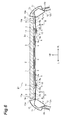
- Fig. 6 is a cross-sectional view illustrating a solar battery mounting structure according to a second embodiment.
- Fig. 7 is a bottom view illustrating a solar battery module 21 according to the second embodiment.
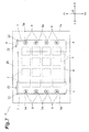
- Fig. 8(a) is an enlarged cross-sectional view of the solar battery module 21 of Fig. 6 .
- Fig. 8(b) is an enlarged bottom view of the solar battery module 21 of Fig. 7 .
- the solar battery mounting structure according to the second embodiment is different from the solar battery mounting structure according to the first embodiment in that positioning pins 22 and 23 are disposed in the lower surface 2b of the glass 2. Furthermore, the same reference numeral is applied to a configuration which is identical to or corresponds to that of the first embodiment, and the repeated description will be omitted.
- the positioning pins 22 and 23 are disposed in the lower surface 2b of the glass 2.
- the positioning pins 22 and 23 are a pin for positioning the fixation portion 5 with respect to the lower surface 2b of the glass 2.
- the positioning pins 22 and 23 are adhered to the lower surface 2b of the glass 2.
- the fixation portion 5 is positioned on the lower surface 2b by the positioning pin 22 which is positioned in the front direction Fr of the vehicle body when viewed from the fixation portion 5, and by the positioning pin 23 which is positioned on an outer side in the horizontal direction. That is, among four side surfaces of the fixation portion 5, a side surface in the front direction Fr is in contact with the positioning pin 22, and a side surface positioned on an outer side of the vehicle body in the horizontal direction is in contact with the positioning pin 23, and thus the fixation portion 5 is positioned with respect to the lower surface 2b of the glass 2.
- the respective positioning pins 22 and 23 are in contact with two sides among four sides of the rectangular fixation portion 5 when viewed from the vertical direction, and thus the fixation portion 5 is positioned.
- the number of positioning pins 22 and 23 or an arrangement thereof is not limited to the number of positioning pins 22 and 23 or the arrangement thereof described above, and three or more positioning pins may be used.
- Fig. 9(a) is a cross-sectional view (a cross-sectional view along the thickness direction of the glass) illustrating a step of arranging members in the manufacturing method of the solar battery module according to the second embodiment.
- Fig. 9(b) is a cross-sectional view (a cross-sectional view along the thickness direction of the glass) illustrating a laminating step in the manufacturing method of the solar battery module according to the second embodiment. Furthermore, a procedure of the step of arranging the members and the laminating step is identical to that of the first embodiment.
- the step of arranging the members illustrated in Fig. 9(a) will be described.
- the positioning pins 22 and 23 are disposed in advance.
- the second sealing material sheet 4B, the solar battery cell 3, the first sealing material sheet 4A, the fixation portion 5, and the back sheet 6 are laminated on the lower surface 2b of the glass 2 in this order.
- the fixation portion 5 is positioned with respect to the lower surface 2b of the glass 2 by being in contact with the positioning pins 22 and 23.
- each of the glasses 2 on which the various members are arranged in the step of arranging the members is input into the laminator, and is pressurized at a high temperature and a uniform pressure.
- the glass 2 is pressed by the metallic mold while being heated by the heat plate H, and thus first sealing material sheet 4A and the second sealing material sheet 4B are pressurized.
- the fixation portion 5 is positioned with respect to the lower surface 2b of the glass 2 by the positioning pins 22 and 23, and thus the fixation portion 5 moves over the sealing material layer 4 and avoids position displacement.
- the protrusion portion 14 is in contact with the lower surface 2b of the glass 2 through sealing material layer 4, and thus the fixation portion 5 does not sink in the sealing material layer 4 and avoids the position displacement in the vertical direction.
- the sealing member 7 is arranged to cover the side of the sealing material layer 4 which is solidified at time intervals. Thus, the solar battery module 21 is manufactured.
- the fixation portion 5 is positioned with respect to the lower surface 2b of the glass 2 by the positioning pins 22 and 23, and thus for example, it is possible to avoid the position displacement of the fixation portion 5 from occurring along the sealing material layer 4 at the time of manufacturing the solar battery module 21. Accordingly, in the solar battery mounting structure, it is possible to suppress the position displacement of the fixation portion 5, and thus it is possible to improve stability of the fixation between the vehicle body frame member B and the solar battery module 1.
- the solar battery module 1 is not disposed immediately on the vehicle body, but may be disposed on a front side of the vehicle body, a back side of the vehicle body, and an inclined surface portion of a lateral side of the vehicle body insofar as such portions are in the upper surface of the vehicle body.
- the solar battery module 1 according to the second embodiment it is not necessary that the positioning pins 22 and 23 be disposed.
- the fixation between the fixation portion of the solar battery module and the fixation surface of the vehicle body frame member is not limited to the structure described above.
- one end of a rod material including a screw groove may be embedded in the fixation portion instead of the nut.
- the nut is screwed from a tip end of the rod material protruding from the bolt hole in a state where the rod material passes through the bolt hole of the fixation surface, and thus it is possible to realize the fixation between the fixation portion and the fixation surface.
- the rod material may include a through hole which is perpendicular to a center shaft of the rod material on the tip end side instead of the screw groove.
- a retaining member is inserted into the through hole on the tip end side protruding from the bolt hole in a state where the rod material is inserted into the bolt hole of the fixation surface, and thus it is possible to realize the fixation between the fixation portion and the fixation surface. Furthermore, in mechanical fixation, there may be slight looseness.
- a base end side of an L-shaped or a flat plate-like metallic plate including a through hole on a tip end side may be embedded.
- the through hole of the metallic plate and a hole in the fixation surface of the vehicle body frame member are caulked in a state of being matched with each other through a rivet and other caulking members, and thus it is possible to realize the fixation between the fixation portion and the fixation surface.
- the fixation portion of the solar battery module and the fixation surface of the vehicle body frame member may be fixed to each other by adhesion.
Landscapes
- Engineering & Computer Science (AREA)
- Chemical & Material Sciences (AREA)
- Combustion & Propulsion (AREA)
- Transportation (AREA)
- Mechanical Engineering (AREA)
- Architecture (AREA)
- Structural Engineering (AREA)
- Photovoltaic Devices (AREA)
Abstract
Description
- The present invention relates to a solar battery mounting structure including a solar battery module fixed to a vehicle body frame member.
- In the related art, for example, Japanese Unexamined Patent Application Publication No.
2010-137809 2010-137809 - Japanese Unexamined Utility Model Registration Application Publication No.
3-117854 2002-043608 2000-352175 2000-068539 - However, the solar battery cell may be used in a configuration of the solar battery module including a light transmissive plate member such as glass on which solar light is incident from an upper surface, and a sealing material layer which is disposed on a lower surface side of the light transmissive plate member and includes the solar battery cell therein. When such a solar battery module is disposed in an upper surface of a vehicle body, the solar battery module is usually mounted on (fixed to) the vehicle body due to adhesion between the light transmissive plate member such as glass and the vehicle body frame member (for example, a roof side rail).
- On the other hand, on the basis of a demand for a reduction in weight of the vehicle from the market, there is a demand for a reduction in a thickness of the light transmissive plate member. However, the reduction in the thickness of the light transmissive plate member which is adhered to the vehicle body frame member causes a decrease in impact resistance of the solar battery module, and thus an improvement for ensuring the impact resistance is required.
- Therefore, in this technical field, there is a demand for providing a solar battery mounting structure by which impact resistance of the solar battery module is able to be ensured.
- The present invention is made in consideration of the circumstances described above, and according to one aspect of the invention, a solar battery mounting structure including a solar battery module which is disposed in an upper surface of a vehicle body and is fixed to a vehicle body frame member, in which the solar battery module includes a light transmissive plate member which is arranged along the upper surface of the vehicle body, an adhesive portion by which a lower surface of a side end portion of the light transmissive plate member is adhered to an adhesive surface of the vehicle body frame member, and a fixation portion which is fixed to a lower surface of the light transmissive plate member through a sealing material layer, and is fixed to a fixation surface of the vehicle body frame member facing the lower surface, a protrusion portion which is in contact with the lower surface of the light transmissive plate member through the sealing material layer is formed in the fixation portion, and in the vehicle body frame member, a step portion is formed between the adhesive surface and the fixation surface, and the fixation surface is separated from the lower surface of the light transmissive plate member compared to the adhesive surface is provided.
- In the solar battery mounting structure, the light transmissive plate member is adhered to the adhesive surface of the vehicle body frame member, and further, the fixation portion is fixed to the fixation surface of the vehicle body frame member, and thus it is possible to increase a fixation point (a connection point) between the vehicle body frame member and the solar battery module, and it is possible to ensure impact resistance of the solar battery module compared to the related art in which only the light transmissive plate member is fixed to the vehicle body frame member. In addition, in the solar battery mounting structure, the protrusion portion which is in contact with the lower surface of the light transmissive plate member through the sealing material layer is formed in the fixation portion, and thus, for example, the fixation portion sinks in the sealing material layer at the time of manufacturing the solar battery module, and it is possible to avoid displacement in a position of the fixation portion. In addition, in the solar battery mounting structure, the step portion is formed between the adhesive surface and the fixation surface, and the fixation surface is separated from the lower surface of the light transmissive plate member compared to the adhesive surface, and thus it is possible to ensure a space for disposing the fixation portion in the sealing material layer compared to a case where the step portion is not included. Accordingly, in the solar battery mounting structure, it is possible to ensure impact resistance of the solar battery module by fixing a portion other than the light transmissive plate member to the vehicle body frame member, and thus it is advantageous for a reduction in a thickness of the light transmissive plate member. This contributes to a reduction in weight of the vehicle on which the solar battery module is mounted.
- In one embodiment, the vehicle body frame member may include a body bracket protruding toward the fixation portion, and the fixation surface may be formed in the body bracket.
- In the solar battery mounting structure, by including the body bracket in the vehicle body frame member, it is possible to form the fixation surface in a suitable position in the vehicle body having various shapes, and thus general versatility is improved.
- In one embodiment, the fixation portion may include a resin member in which a nut is embedded, the fixation surface has a bolt hole opened therein, and the fixation portion may be fixed to the fixation surface by a bolt may be screwed into the nut through the bolt hole.
- In the solar battery mounting structure, the nut and the bolt of the resin member are screwed in a state where a shaft portion of the bolt is inserted into the bolt hole in the fixation surface of the vehicle body frame member, and thus it is possible to fix the fixation portion of the solar battery module to the fixation surface of the vehicle body frame member in a comparatively easy configuration. In addition, in the solar battery mounting structure, the step portion is formed between the adhesive surface and the fixation surface in the vehicle body frame member, and thus it is possible to ensure an arrangement space of the nut by the step, and it is possible to obtain necessary strength by sufficiently taking a length for screwing the nut and the bolt.
- In one embodiment, a plurality of positioning pins for positioning the fixation portion at the time of manufacturing the solar battery module may be disposed in the lower surface of the light transmissive plate member.
- In the solar battery mounting structure, the fixation portion is positioned with respect to the lower surface of the light transmissive plate member by the plurality of positioning pins, and thus position displacement of the fixation portion is avoided at the time of forming the sealing material layer in manufacturing of the solar battery module. Accordingly, in the solar battery mounting structure, it is possible to suppress the position displacement of the fixation portion, and thus it is possible to improve stability of fixation between the solar battery module and the vehicle body frame member.
- In one embodiment, a back sheet which is disposed on a side of the sealing material layer opposite to the light transmissive plate member may be further included.
- According to the solar battery mounting structure, it is possible to improve strength of the sealing material layer by the back sheet which is disposed on the side of the sealing material layer opposite to the light transmissive plate member. This contributes to an improvement in durability of the solar battery module.
- According to the solar battery mounting structure of the aspect and each of the embodiments of the invention, it is possible to ensure impact resistance of the solar battery module.
-
-
Fig. 1 is a cross-sectional view illustrating a solar battery mounting structure according to a first embodiment. -
Fig. 2 is a bottom view illustrating a solar battery module ofFig. 1 . -
Fig. 3(a) is an enlarged cross-sectional view of the solar battery module ofFig. 1 , andFig. 3(b) is an enlarged bottom view of the solar battery module ofFig. 2 . -
Fig. 4(a) is an enlarged cross-sectional view illustrating the solar battery module fixed to the vehicle body frame member, andFig. 4(b) is an enlarged bottom view illustrating the solar battery module fixed to the vehicle body frame member. -
Fig. 5(a) is a cross-sectional view (a cross-sectional view along a thickness direction of glass) illustrating a step of arranging members in a manufacturing method of the solar battery module according to the first embodiment, andFig. 5(b) is a cross-sectional view (a cross-sectional view along the thickness direction of the glass) illustrating a laminating step of the solar battery module according to the first embodiment. -
Fig. 6 is a cross-sectional view illustrating a solar battery mounting structure according to a second embodiment. -
Fig. 7 is a bottom view illustrating a solar battery module ofFig. 6 . -
Fig. 8(a) is an enlarged cross-sectional view of the solar battery module ofFig. 6 , andFig. 8(b) is an enlarged bottom view of the solar battery module ofFig. 7 . -
Fig. 9(a) is a cross-sectional view (a cross-sectional view along a thickness direction of glass) illustrating a step of arranging members in a manufacturing method of the solar battery module according to the second embodiment, andFig. 9(b) is a cross-sectional view (a cross-sectional view along the thickness direction of the glass) illustrating a laminating step in the manufacturing method of the solar battery module according to the second embodiment. - Hereinafter, preferred embodiments of the invention will be described in detail with reference to the drawings.
- As illustrated in
Fig. 1 , a solar battery mounting structure according to a first embodiment is a structure for mounting asolar battery module 1 on a vehicle body. A type of the vehicle body including thesolar battery module 1 mounted thereon is not particularly limited, and may be a vehicle body of a passenger vehicle, may be a vehicle body of a shared vehicle such as a bus, or may be a vehicle body of a freight vehicle such as a van or a truck. InFig. 1 , an upper direction UP, a left direction L, and a right direction R of the vehicle body are illustrated by arrows. - The
solar battery module 1 is fixed to a vehicle body frame member B configuring the vehicle body. The vehicle body frame member B includes a roof side rail, a roof panel, a roof panel reinforcement, and the like, which constitute the vehicle body. Furthermore, the vehicle body frame member B to which thesolar battery module 1 is fixed may include a front body pillar, a center body pillar, a side outer panel, and the like. - The
solar battery module 1 according to the first embodiment is disposed in an upper surface of the vehicle body, and may configure a part of a roof of the vehicle body. Specifically, thesolar battery module 1 is fixed to a pair of right and left roof side rails Rs configuring the vehicle body frame member B. The upper surface of the vehicle body, for example, is an upper surface of a roof panel (not illustrated) supported by the roof side rail Rs. The upper surface of the roof panel, for example, is positioned between upper ends of the pair of roof side rails Rs. - Hereinafter, a configuration of the roof side rail Rs will be described. The roof side rail Rs is configured by a roof
side rail reinforcement 11 arranged on a vehicle exterior side, and a roof sideinner rail 12. - An
upper end portion 12a of the roof sideinner rail 12 is overlapped with anupper end portion 11 a of the roofside rail reinforcement 11. In addition, alower end portion 11b of the roofside rail reinforcement 11 is overlapped with alower end portion 12b of the roof sideinner rail 12. A vertical cross section of the roofside rail reinforcement 11 and the roof sideinner rail 12 forms a closed cross section. Theupper end portion 11 a side of the roofside rail reinforcement 11 extends toward an inner side (a cabin side) from theupper end portion 12a of the roof sideinner rail 12. - In addition, a side
outer panel 13 is arranged outside the roofside rail reinforcement 11. Anupper end portion 13a of the sideouter panel 13 is overlapped with theupper end portion 11 a of the roofside rail reinforcement 11. That is, theupper end portion 11a of the roofside rail reinforcement 11 is interposed between theupper end portion 13 a of the sideouter panel 13 and theupper end portion 12a of the roof sideinner rail 12 in a vertical direction. - The
upper end portion 11a of the roofside rail reinforcement 11 protrudes toward thesolar battery module 1 from theupper end portion 13a of the sideouter panel 13 and theupper end portion 12a of the roof sideinner rail 12. Thesolar battery module 1 is fixed to an upper surface of theupper end portion 11 a. - Subsequently, a configuration of the
solar battery module 1 will be described. Thesolar battery module 1 includes plate-like glass 2 which is able to transmit light, asolar battery cell 3, a sealingmaterial layer 4, afixation portion 5, aback sheet 6, and asealing member 7. - The
glass 2 is arranged along an upper surface of the vehicle body, and is a rectangular light transmissive plate member having light permeability which transmits solar light. Theglass 2 is a plate member having an upper surface (a front surface) 2a on which the solar light is incident. In addition, theglass 2 has a suitable thickness for ensuring strength of thesolar battery module 1. Theglass 2 may be in the shape of a flat plate shape, or may be in the shape of a curved plate. In this embodiment, theglass 2 is in the shape of a flat plate, and a thickness direction of theglass 2 is identical to the vertical direction. Furthermore, instead of theglass 2, a plate member formed of a light permeability resin such as acryl, polyethylene terephthalate (PET), polyethylene naphthalate (PEN), and polycarbonate may be used. - The
glass 2 is arranged over the pair of right and left roof side rails Rs. A lower surface (a back surface) 2b of theglass 2 is adhered to each of the pair of roof side rails Rs. Theglass 2 is fixed to the roof side rail Rs by a so-called direct grading method, and an adhesive portion S is disposed between theglass 2 and the roof side rail Rs. - The adhesive portion S is fixed by adhesion between the pair of roof side rails Rs and the
glass 2. The adhesive portion S, for example, is formed of a urethane resin. Furthermore, the adhesive portion S is not limited to the adhesive portion formed of the urethane resin, and may be formed of other known adhesive agents. - Specifically, the adhesive portion S is formed between each
lower surface 2b of a pair ofside end portions glass 2, and each adhesive surface F1 of the pair of roof side rails Rs. The pair ofside end portions glass 2 are end portions of the vehicle body in a width direction which face each other in a horizontal direction. The adhesive surface F1 is an upper surface of the roof side rail Rs (the roof side rail reinforcement 11) facing thelower surface 2b of the pair ofside end portions lower surface 2b of the pair ofside end portions glass 2 is adhered to the adhesive surface F1 of the pair of roof side rails Rs. - Furthermore, in the
glass 2, not only thelower surface 2b of the pair ofside end portions lower surface 2b of the pair of side end portions which face each other in a front-back direction is adhered to the vehicle body frame member B (for example, the roof panel reinforcement). - On a center side of the
lower surface 2b of theglass 2, the sealingmaterial layer 4 including thesolar battery cell 3 therein is disposed. The sealingmaterial layer 4 is disposed between a pair of adhesive portions S. Thesolar battery cell 3 is an instrument converting light energy into direct power by using a photovoltaic effect, and for example, a silicon-basedsolar battery cell 3 is used. As the silicon-basedsolar battery cell 3, any one of a single crystalline silicon-based solar battery cell, a polycrystalline silicon-based solar battery cell, and an amorphous silicon-based solar battery cell may be used. The single crystalline silicon-based solar battery cell has excellent photoelectric conversion efficiency, and the amorphous silicon-based solar battery cell has smaller efficiency degradation due to an increase in temperature. In addition, as thesolar battery cell 3, a known solar battery cell is able to be adopted, and a solar battery cell of a compound such as GaAs (gallium arsenide) or an organic solar battery cell, and other solar battery cells may be used. - The sealing
material layer 4 is a layer protecting thesolar battery cell 3 from being degraded due to moisture, oxygen, or the like by sealing thesolar battery cell 3. The sealingmaterial layer 4 is formed of a light permeability resin. Specifically, as the sealingmaterial layer 4, for example, Ethylene Vinyl Acetate (EVA), Poly Vinyl Butyral (PVB), an ion crosslinked polyolefin-based resin, and the like are able to be adopted. - Here,
Fig. 2 is a bottom view illustrating thesolar battery module 1. InFig. 2 , a front direction Fr of the vehicle body and a back direction Rr of the vehicle body are illustrated by arrows in addition to the upper direction UP of the vehicle body, the left direction L of the vehicle body, and the right direction R of the vehicle body. - As illustrated in
Fig. 1 andFig. 2 , a plurality ofsolar battery cells 3 are arranged on the same plane inside the sealingmaterial layer 4. In this embodiment, as an example, a total of 16 (4 sheets × 4 rows)solar battery cells 3 are arranged at predetermined intervals. Furthermore, the number ofsolar battery cells 3 or an arrangement thereof is not limited to the number ofsolar battery cells 3 or the arrangement thereof illustrated inFig. 1 andFig. 2 . - On a side of the sealing
material layer 4 opposite to the glass 2 (a lower surface side), a pair of right and leftfixation portions 5 are disposed. Thefixation portion 5 is fixed to thelower surface 2b of theglass 2 through the sealingmaterial layer 4. Thefixation portion 5 is a portion which is fixed to the vehicle body frame member B. Fixation of thefixation portion 5 will be described later in detail. - On the side of the sealing
material layer 4 opposite to theglass 2, theback sheet 6 is arranged between the pair of right and leftfixation portions 5. Theback sheet 6, for example, is a multilayered resin film, and is disposed to cover the sealingmaterial layer 4. In addition, anend portion 6a of theback sheet 6 in the horizontal direction is arranged to be overlapped on thefixation portion 5. Theback sheet 6 prevents moisture, oxygen, or the like from invading (infiltration) the sealingmaterial layer 4. Furthermore, it is not necessary that theback sheet 6 be arranged to be overlapped with thefixation portion 5, and for example, a sealing member such as a butyl tape may be disposed to cover a gap between theback sheet 6 and thefixation portion 5. - As a material of the
back sheet 6, for example a fluoride resin such as polyvinylidene fluoride (PVF), and an ester resin such as polyethylene terephthalate (PET) are able to be adopted, and as necessary, a metallic film is able to be interposed between layers. Theback sheet 6 improves strength of the sealingmaterial layer 4, and contributes to an improvement in durability of thesolar battery module 1. - A side of the sealing
material layer 4 is covered with the sealingmember 7. The sealingmember 7 is a member for preventing moisture, oxygen, or the like from invading (infiltrating) the sealingmaterial layer 4. The sealingmember 7 is not particularly limited insofar as the sealingmaterial layer 4 is able to be protected by a configuration of the sealingmember 7. As the sealingmember 7, for example, a butyl tape is able to be adopted. - Subsequently, fixation between the
fixation portion 5 and the vehicle body frame member B will be described. Here, thefixation portion 5 and the vehicle body frame member B are mechanically fixed to each other by using anut 9 and abolt 10. Furthermore, a fixing method of thefixation portion 5 and the vehicle body frame member B is not limited to the fixing method using thenut 9 and thebolt 10. Other fixing methods will be described later. - First, the
fixation portion 5 will be described. Thefixation portion 5 is a plate-like resin member which is disposed to cover right and left end portions of the sealingmaterial layer 4 on the side of the sealingmaterial layer 4 opposite to theglass 2. Thefixation portion 5 is in the shape of a rectangle of which a longitudinal direction is the front-back direction of the vehicle body. As a material of thefixation portion 5, a polyamide, polypropylene, and polyethylene terephthalate are able to be adopted. Fibers or fillers may be included in these resins. Thefixation portion 5 also functions as a sealing member which inhibits moisture, oxygen, or the like from invading (infiltrating) the sealingmaterial layer 4. - Here,
Fig. 3(a) is an enlarged cross-sectional view of thesolar battery module 1 ofFig. 1 .Fig. 3(b) is an enlarged bottom view of thesolar battery module 1 ofFig. 2 . As illustrated inFig. 2 andFigs. 3(a) and 3(b) , thefixation portion 5 is molded in a state where thenut 9 is inserted, and includes fourthick portions 5 a in which thenut 9 is embedded. The fourthick portions 5a are formed at predetermined intervals by being arranged in the front-back direction of the vehicle body. Thethick portion 5a is formed along an outer side (the sealingmember 7 side) of thefixation portion 5 in the horizontal direction. Thethick portion 5a is a portion in which a resin is formed to be thick in order to maintain thenut 9 with sufficient strength. Furthermore, a thickness of thefixation portion 5 may be approximately uniform but for thethick portion 5a. - As the
nut 9, a known nut is able to be adopted, and for example, an insert nut in which concavities and convexities are formed on an outer circumferential surface is able to be adopted. Thenut 9 is embedded in the center of thethick portion 5 a such that a female screw portion is exposed when viewed from the bottom. Furthermore, the number ofthick portions 5a and the number ofnuts 9 are not limited to four, and may be one or more. In addition, the entire thickness of thefixation portion 5 may be identical to a thickness of thethick portion 5a. A size or an arrangement of thenut 9 is not limited to the size or the arrangement illustrated in the drawings. -
Fig. 4(a) is an enlarged cross-sectional view illustrating thesolar battery module 1 fixed to the vehicle body frame member B.Fig. 4(a) is an enlarged bottom view illustrating thesolar battery module 1 fixed to the vehicle body frame member B. As illustrated inFig. 1 andFigs. 4(a) and 4(b) , the vehicle body frame member B includes abody bracket 8 which is fixed to the roof side rail Rs. - The
body bracket 8, for example, is an elongated metallic plate member extending in the front-back direction of the vehicle body along thefixation portion 5. Thebody bracket 8 is divided into abase end portion 8a, atip end portion 8b, and astep portion 8c in the horizontal direction. Thebase end portion 8a is a portion which is fixed to the roof side rail Rs. Specifically, thebase end portion 8a is welded to a back surface (a lower surface) of the adhesive surface F1 of the roof side rail Rs. - The
tip end portion 8b is a portion in which a fixation surface F2 fixed to thefixation portion 5 is formed. The fixation surface F2 is a surface of thetip end portion 8b facing thelower surface 2b of theglass 2 in the vertical direction. Specifically, the fixation surface F2 faces thefixation portion 5 in the vertical direction. - In addition, the fixation surface F2 is separated from the
lower surface 2b of theglass 2 in the vertical direction compared to the adhesive surface F1. InFig. 4(a) , a difference D between a height of the adhesive surface F1 and a height of the fixation surface F2 is illustrated. The difference D in the heights, for example, may be 3 mm to 10 mm. - In the fixation surface F2 of the
tip end portion 8b, a bolt hole A into which thebolt 10 is inserted is formed to be opened. In the fixation surface F2, four bolt holes A corresponding to positions of the fournuts 9 are formed to be opened. Thebolt 10 is screwed into thenut 9 of thefixation portion 5 through the bolt hole A, and thus thefixation portion 5 and thebody bracket 8 are fixed to each other. That is, thefixation portion 5 of thesolar battery module 1 and the fixation surface F2 of thebody bracket 8 of the vehicle body frame member B are mechanically fixed to each other by thebolt 10 and thenut 9. As thebolt 10, a known bolt is able to be adopted. - In addition, the bolt hole A is formed as a long hole extending in the horizontal direction. Thus, by forming the bolt hole A as the long hole, the
bolt 10 is able to be screwed into thenut 9 through the bolt hole A even when slight displacement of thefixation portion 5 and the fixation surface F2 occurs, and it is possible to make attachment work of thesolar battery module 1 easy. Furthermore, an extending direction of the long hole in the bolt hole A is not limited to the horizontal direction, and for example, may be the front-back direction of the vehicle body. - The
step portion 8c is a portion which is formed between thebase end portion 8a and thetip end portion 8b. Thestep portion 8c is formed to be lowered as approaching thefixation portion 5, and thetip end portion 8b is positioned below thebase end portion 8a. In the vehicle body frame member B, the difference D between the adhesive surface F1 and fixation surface F2 in a height direction due to thestep portion 8c is sufficiently ensured. - Furthermore, it is not necessary that the
body bracket 8 include four bolt holes A such that onebody bracket 8 corresponds to all of thenuts 9, and onebody bracket 8 may include only two bolt holes A. In addition, thebody bracket 8 may include only one bolt hole A, and may be individually disposed on eachnut 9. - In addition, it is not necessary that the vehicle body frame member B include the
body bracket 8, and for example, both the adhesive surface F1 and the fixation surface F2 may be formed in the roof side rail Rs. In this case, in the roof side rail Rs, the step portion between the adhesive surface F1 and the fixation surface F2 is also formed. Alternatively, both the adhesive surface F1 and the fixation surface F2 may be formed in thebody bracket 8. - In addition, the
fixation portion 5 includes aprotrusion portion 14 protruding toward thelower surface 2b of theglass 2. Fourprotrusion portions 14, for example, are disposed in eachthick portion 5a (in each nut 9). The fourprotrusion portions 14 are arranged to surround thenut 9. The fourprotrusion portions 14, for example, are disposed at equal intervals in a circumferential direction of thenut 9. Theprotrusion portion 14, for example, is formed into the shape of a column, and is in contact with thelower surface 2b of theglass 2 through the sealingmaterial layer 4. - Furthermore, the number of
protrusion portions 14 is not limited to four, and may be one. In addition, an arrangement of theprotrusion portion 14 is not limited to the arrangement described above. A shape of theprotrusion portion 14 is not limited to a columnar shape, and may have any shape insofar as theprotrusion portion 14 is able to be in contact with thelower surface 2b of theglass 2 through the sealingmaterial layer 4. In addition, theprotrusion portion 14, for example, is able to be formed of a resin. In this case, theprotrusion portion 14 is able to be integrally formed with thefixation portion 5 which is formed of a resin. Theprotrusion portion 14 may be formed of metal and other materials. - In the solar battery mounting structure according to the first embodiment described above, the
glass 2 is adhered to the adhesive surface F1 of the vehicle body frame member B, and further, thefixation portion 5 is fixed to the fixation surface F2 of the vehicle body frame member B, and thus it is possible to increase a fixation point (a connection point) between thesolar battery module 1 and the vehicle body frame member B, and it is possible to ensure impact resistance of thesolar battery module 1 compared to the related art in which only theglass 2 is fixed to the vehicle body frame member B. In addition, in the solar battery mounting structure, thestep portion 8c is formed between the adhesive surface F1 and the fixation surface F2 of the vehicle body frame member B, and the fixation surface F2 is separated from thelower surface 2b of theglass 2 compared to the adhesive surface F1, and thus it is possible to ensure a space for disposing thefixation portion 5 in the sealingmaterial layer 4 compared to a case where thestep portion 8c is not included. Accordingly, in the solar battery mounting structure, it is possible to ensure impact resistance of thesolar battery module 1 by fixing a portion other than theglass 2 to the vehicle body frame member B, and thus it is advantageous for a reduction in a thickness of theglass 2. This contributes to a reduction in weight of the vehicle on which thesolar battery module 1 is mounted. - In addition, in the solar battery mounting structure, the
protrusion portion 14 which is formed on the sealingmaterial layer 4 side of thefixation portion 5 is in contact with thelower surface 2b of theglass 2, and thus for example, thefixation portion 5 sinks in the sealingmaterial layer 4 at the time of manufacturing thesolar battery module 1, and it is possible to avoid displacement from occurring in the position of thefixation portion 5. This improves reliability of a connection between the vehicle body frame member B and thesolar battery module 1, and thus contributes to an improvement in impact resistance of thesolar battery module 1. - In addition, in the solar battery mounting structure, by including the body bracket in the vehicle body frame member B, it is possible to dispose the fixation surface F2 in a suitable position in the vehicle body having various shapes, and thus general versatility is improved.
- Further, in the solar battery mounting structure, the
nut 9 and thebolt 10 in thefixation portion 5 are screwed in a state where a shaft portion of thebolt 10 is inserted into the bolt hole A in the fixation surface F2 of the vehicle body frame member B, and thus it is possible to fix thefixation portion 5 of thesolar battery module 1 to the fixation surface F2 of the vehicle body frame member B in a comparatively easy configuration. In addition, in the solar battery mounting structure, thestep portion 8c is formed between the adhesive surface F1 and the fixation surface F2 in the vehicle body frame member B, and thus it is possible to ensure an arrangement space of thenut 9 by the step, and it is possible to obtain necessary strength by sufficiently taking a length for screwing thenut 9 and thebolt 10. - Next, the manufacturing method of the
solar battery module 1 according to the first embodiment will be described with reference toFigs. 5(a) and 5(b). Fig. 5(a) is a cross-sectional view illustrating a step of arranging members in the manufacturing method of thesolar battery module 1.Fig. 5(b) is a cross-sectional view illustrating a laminating step in the manufacturing method of thesolar battery module 1. InFig. 5(a) and Fig. 5(b) , thesolar battery module 1 is illustrated as being upside down fromFig. 1 . - First, the step of arranging the members illustrated in
Fig. 5(a) will be described. In the step of arranging the members, as a base of theglass 2, various members are arranged on thelower surface 2b of theglass 2. Specifically, a secondsealing material sheet 4B, thesolar battery cell 3, a firstsealing material sheet 4A, thefixation portion 5, and theback sheet 6 are laminated on thelower surface 2b of theglass 2 in this order. The sealingmaterial sheets material layer 4 is formed. - At this time, the
fixation portion 5 is arranged such that theprotrusion portion 14 is in contact with thelower surface 2b of theglass 2 through the firstsealing material sheet 4A and the secondsealing material sheet 4B. Furthermore, in the firstsealing material sheet 4A and the secondsealing material sheet 4B, a hole into which theprotrusion portion 14 is inserted may be formed in advance. In addition, in thefixation portion 5, thenut 9 is embedded in advance. - Subsequently, the laminating step illustrated in
Fig. 5(b) will be described. In the laminating step, eachglass 2 on which the various members are arranged in the step of arranging the members is input into a laminator, and is pressurized at a high temperature and a uniform pressure. In the laminator, theglass 2 is arranged on a heat plate H, and the various members on each of theglasses 2 are covered with rubber E of the laminator. In this state, theglass 2 is pressed by a metallic mold while being heated by the heat plate H, and thus each sheet is pressurized. After finishing the laminating step, the sealingmember 7 is arranged to cover the side of the sealingmaterial layer 4 which is solidified at time intervals. Thus, thesolar battery module 1 is manufactured. - According to the manufacturing method of the
solar battery module 1 according to the first embodiment described above, formation of the sealingmaterial layer 4 and attachment of thefixation portion 5 are able to be performed at once in the laminating step, and thus it is possible to efficiently manufacture thesolar battery module 1. Furthermore, thefixation portion 5 is able to be formed of a resin of which a softening temperature is greater than or equal to 120°C in order to avoid thefixation portion 5 from being softened in the laminating step. -
Fig. 6 is a cross-sectional view illustrating a solar battery mounting structure according to a second embodiment.Fig. 7 is a bottom view illustrating asolar battery module 21 according to the second embodiment.Fig. 8(a) is an enlarged cross-sectional view of thesolar battery module 21 ofFig. 6 .Fig. 8(b) is an enlarged bottom view of thesolar battery module 21 ofFig. 7 . - As illustrated in
Fig. 6 to Fig. 8(b) , the solar battery mounting structure according to the second embodiment is different from the solar battery mounting structure according to the first embodiment in that positioning pins 22 and 23 are disposed in thelower surface 2b of theglass 2. Furthermore, the same reference numeral is applied to a configuration which is identical to or corresponds to that of the first embodiment, and the repeated description will be omitted. - As illustrated in
Fig. 7 andFigs. 8(a) and 8(b) , the positioning pins 22 and 23 are disposed in thelower surface 2b of theglass 2. The positioning pins 22 and 23 are a pin for positioning thefixation portion 5 with respect to thelower surface 2b of theglass 2. The positioning pins 22 and 23 are adhered to thelower surface 2b of theglass 2. - The
fixation portion 5 is positioned on thelower surface 2b by thepositioning pin 22 which is positioned in the front direction Fr of the vehicle body when viewed from thefixation portion 5, and by thepositioning pin 23 which is positioned on an outer side in the horizontal direction. That is, among four side surfaces of thefixation portion 5, a side surface in the front direction Fr is in contact with thepositioning pin 22, and a side surface positioned on an outer side of the vehicle body in the horizontal direction is in contact with thepositioning pin 23, and thus thefixation portion 5 is positioned with respect to thelower surface 2b of theglass 2. In other words, the respective positioning pins 22 and 23 are in contact with two sides among four sides of therectangular fixation portion 5 when viewed from the vertical direction, and thus thefixation portion 5 is positioned. Furthermore, the number of positioning pins 22 and 23 or an arrangement thereof is not limited to the number of positioning pins 22 and 23 or the arrangement thereof described above, and three or more positioning pins may be used. - Here, a manufacturing method of the
solar battery module 21 according to the second embodiment will be described with reference toFigs. 9(a) and 9(b). Fig. 9(a) is a cross-sectional view (a cross-sectional view along the thickness direction of the glass) illustrating a step of arranging members in the manufacturing method of the solar battery module according to the second embodiment.Fig. 9(b) is a cross-sectional view (a cross-sectional view along the thickness direction of the glass) illustrating a laminating step in the manufacturing method of the solar battery module according to the second embodiment. Furthermore, a procedure of the step of arranging the members and the laminating step is identical to that of the first embodiment. - First, the step of arranging the members illustrated in
Fig. 9(a) will be described. Here, in thelower surface 2b of theglass 2, the positioning pins 22 and 23 are disposed in advance. In the step of arranging the members, the secondsealing material sheet 4B, thesolar battery cell 3, the firstsealing material sheet 4A, thefixation portion 5, and theback sheet 6 are laminated on thelower surface 2b of theglass 2 in this order. At this time, thefixation portion 5 is positioned with respect to thelower surface 2b of theglass 2 by being in contact with the positioning pins 22 and 23. - Subsequently, the laminating step illustrated in
Fig. 9(b) will be described. In the laminating step, each of theglasses 2 on which the various members are arranged in the step of arranging the members is input into the laminator, and is pressurized at a high temperature and a uniform pressure. In the laminator, theglass 2 is pressed by the metallic mold while being heated by the heat plate H, and thus first sealingmaterial sheet 4A and the secondsealing material sheet 4B are pressurized. At this time, thefixation portion 5 is positioned with respect to thelower surface 2b of theglass 2 by the positioning pins 22 and 23, and thus thefixation portion 5 moves over the sealingmaterial layer 4 and avoids position displacement. Further, theprotrusion portion 14 is in contact with thelower surface 2b of theglass 2 through sealingmaterial layer 4, and thus thefixation portion 5 does not sink in the sealingmaterial layer 4 and avoids the position displacement in the vertical direction. After finishing the laminating step, the sealingmember 7 is arranged to cover the side of the sealingmaterial layer 4 which is solidified at time intervals. Thus, thesolar battery module 21 is manufactured. - In the solar battery mounting structure according to the second embodiment described above, the same effects as those of the solar battery mounting structure according to the first embodiment are able to be obtained. Further, in the solar battery mounting structure, the
fixation portion 5 is positioned with respect to thelower surface 2b of theglass 2 by the positioning pins 22 and 23, and thus for example, it is possible to avoid the position displacement of thefixation portion 5 from occurring along the sealingmaterial layer 4 at the time of manufacturing thesolar battery module 21. Accordingly, in the solar battery mounting structure, it is possible to suppress the position displacement of thefixation portion 5, and thus it is possible to improve stability of the fixation between the vehicle body frame member B and thesolar battery module 1. - As described above, the embodiment of the invention is described, but the structure of the invention is not limited to the embodiment described above. For example, the
solar battery module 1 is not disposed immediately on the vehicle body, but may be disposed on a front side of the vehicle body, a back side of the vehicle body, and an inclined surface portion of a lateral side of the vehicle body insofar as such portions are in the upper surface of the vehicle body. In addition, in thesolar battery module 1 according to the second embodiment, it is not necessary that the positioning pins 22 and 23 be disposed. - In addition, the fixation between the fixation portion of the solar battery module and the fixation surface of the vehicle body frame member is not limited to the structure described above. Specifically, one end of a rod material including a screw groove may be embedded in the fixation portion instead of the nut. In this case, the nut is screwed from a tip end of the rod material protruding from the bolt hole in a state where the rod material passes through the bolt hole of the fixation surface, and thus it is possible to realize the fixation between the fixation portion and the fixation surface. In addition, the rod material may include a through hole which is perpendicular to a center shaft of the rod material on the tip end side instead of the screw groove. In this case, a retaining member is inserted into the through hole on the tip end side protruding from the bolt hole in a state where the rod material is inserted into the bolt hole of the fixation surface, and thus it is possible to realize the fixation between the fixation portion and the fixation surface. Furthermore, in mechanical fixation, there may be slight looseness.
- In addition, in the fixation portion, a base end side of an L-shaped or a flat plate-like metallic plate including a through hole on a tip end side may be embedded. In this case, the through hole of the metallic plate and a hole in the fixation surface of the vehicle body frame member are caulked in a state of being matched with each other through a rivet and other caulking members, and thus it is possible to realize the fixation between the fixation portion and the fixation surface. In addition, the fixation portion of the solar battery module and the fixation surface of the vehicle body frame member may be fixed to each other by adhesion.
Claims (5)
- A solar battery mounting structure comprising a solar battery module which is disposed in an upper surface of a vehicle body and is fixed to a vehicle body frame member,
wherein the solar battery module includes
a light transmissive plate member which is arranged along the upper surface of the vehicle body,
an adhesive portion by which a lower surface of a side end portion of the light transmissive plate member is adhered to an adhesive surface of the vehicle body frame member, and
a fixation portion which is fixed to a lower surface of the light transmissive plate member through a sealing material layer, and is fixed to a fixation surface of the vehicle body frame member facing the lower surface,
a protrusion portion which is in contact with the lower surface of the light transmissive plate member through the sealing material layer is formed in the fixation portion, and
in the vehicle body frame member, a step portion is formed between the adhesive surface and the fixation surface, and the fixation surface is separated from the lower surface of the light transmissive plate member compared to the adhesive surface. - The solar battery mounting structure according to Claim 1,
wherein the vehicle body frame member includes a body bracket protruding toward the fixation portion, and
the fixation surface is formed in the body bracket. - The solar battery mounting structure according to Claim 1 or 2,
wherein the fixation portion includes a resin member in which a nut is embedded,
the fixation surface has a bolt hole opened therein, and
the fixation portion is fixed to the fixation surface by a bolt is screwed into the nut through the bolt hole. - The solar battery mounting structure according to any one of Claims 1 to 3,
wherein a plurality of positioning pins for positioning the fixation portion at the time of manufacturing the solar battery module are disposed in the lower surface of the light transmissive plate member. - The solar battery mounting structure according to any one of Claims 1 to 4, further comprising:a back sheet which is disposed on a side of the sealing material layer opposite to the light transmissive plate member.
Applications Claiming Priority (1)
| Application Number | Priority Date | Filing Date | Title |
|---|---|---|---|
| JP2014037522A JP5835375B2 (en) | 2014-02-27 | 2014-02-27 | Solar cell mounting structure |
Publications (3)
| Publication Number | Publication Date |
|---|---|
| EP2913252A2 true EP2913252A2 (en) | 2015-09-02 |
| EP2913252A3 EP2913252A3 (en) | 2015-09-09 |
| EP2913252B1 EP2913252B1 (en) | 2017-08-02 |
Family
ID=52633074
Family Applications (1)
| Application Number | Title | Priority Date | Filing Date |
|---|---|---|---|
| EP15156072.9A Active EP2913252B1 (en) | 2014-02-27 | 2015-02-23 | Solar battery mounting structure in a vehicle |
Country Status (4)
| Country | Link |
|---|---|
| US (1) | US9327597B2 (en) |
| EP (1) | EP2913252B1 (en) |
| JP (1) | JP5835375B2 (en) |
| CN (1) | CN104883119A (en) |
Cited By (3)
| Publication number | Priority date | Publication date | Assignee | Title |
|---|---|---|---|---|
| WO2017162292A1 (en) * | 2016-03-24 | 2017-09-28 | Volvo Truck Corporation | A vehicle cab body for a vehicle |
| EP3422565A1 (en) * | 2017-06-30 | 2019-01-02 | Beijing Hanergy Solar Power Investment Co., Ltd. | Solar support mounted on a vehicle roof |
| WO2023242441A1 (en) * | 2022-06-17 | 2023-12-21 | Lightyear Layer Ipco B.V. | Integrating a solar panel in a vehicle body part |
Families Citing this family (14)
| Publication number | Priority date | Publication date | Assignee | Title |
|---|---|---|---|---|
| NO169570C (en) | 1989-01-30 | 1992-07-08 | Svein Hestevik | PROCEDURE FOR MANUFACTURING SUBSTRATE FOR APPLICATION OF ELECTRICAL AND / OR ELECTRONIC COMPONENTS. |
| JP2015131612A (en) * | 2014-01-15 | 2015-07-23 | トヨタ自動車株式会社 | Solar cell panel for vehicle |
| US9649948B2 (en) | 2014-08-25 | 2017-05-16 | Ford Global Technologies, Llc | Self-locating multi-coil system for wireless vehicle charging |
| US9481241B2 (en) * | 2014-09-30 | 2016-11-01 | Ford Global Technologies, Llc | Cooling system for a vehicle solar panel |
| JP6595521B2 (en) * | 2017-02-08 | 2019-10-23 | トヨタ自動車株式会社 | Body superstructure |
| DE102017110128B4 (en) * | 2017-05-10 | 2024-12-12 | Webasto SE | Vehicle window with an attachment part attached to the inside |
| US10193494B2 (en) * | 2017-05-26 | 2019-01-29 | Ford Global Technologies, Llc | Vehicle glass roof systems |
| WO2019071013A1 (en) | 2017-10-04 | 2019-04-11 | Shape Corp. | Battery tray floor assembly for electric vehicles |
| CN107640060B (en) * | 2017-10-31 | 2023-12-05 | 安徽易威斯新能源科技股份有限公司 | Energy storage fills electric pile |
| JP6985133B2 (en) * | 2017-12-20 | 2021-12-22 | トヨタ自動車株式会社 | Solar cell module |
| CN111655548A (en) * | 2018-02-02 | 2020-09-11 | 康明斯公司 | System for thermal management of batteries |
| CN108189676A (en) * | 2018-03-07 | 2018-06-22 | 福州艾弗斯智能科技有限公司 | A kind of solar telephone top plate |
| JP7518636B2 (en) * | 2020-03-10 | 2024-07-18 | 株式会社カネカ | Solar cell module and method for manufacturing solar cell module |
| CN112993070B (en) * | 2021-04-20 | 2026-01-09 | 天合光能股份有限公司 | A non-uniform battery module |
Citations (5)
| Publication number | Priority date | Publication date | Assignee | Title |
|---|---|---|---|---|
| JPH03117854U (en) | 1990-03-15 | 1991-12-05 | ||
| JP2000068539A (en) | 1998-08-19 | 2000-03-03 | Honda Motor Co Ltd | Concentrating tracking power generator |
| JP2000352175A (en) | 1999-06-11 | 2000-12-19 | Maeda Corp | External facing panel |
| JP2002043608A (en) | 2000-07-28 | 2002-02-08 | Japan Storage Battery Co Ltd | Solar power generator |
| JP2010137809A (en) | 2008-12-15 | 2010-06-24 | Toyota Motor Corp | Vehicle upper structure |
Family Cites Families (40)
| Publication number | Priority date | Publication date | Assignee | Title |
|---|---|---|---|---|
| GB1227417A (en) * | 1967-04-06 | 1971-04-07 | ||
| US4090577A (en) * | 1977-04-18 | 1978-05-23 | Moore Wallace H | Solar celled hybrid vehicle |
| US4461922A (en) * | 1983-02-14 | 1984-07-24 | Atlantic Richfield Company | Solar cell module |
| US4638111A (en) * | 1985-06-04 | 1987-01-20 | Atlantic Richfield Company | Thin film solar cell module |
| JPH0724279Y2 (en) | 1988-05-10 | 1995-06-05 | 本田技研工業株式会社 | Sunroof panel waterproof structure |
| DE3835560A1 (en) * | 1988-10-19 | 1990-04-26 | Kaaden Hans Heinrich | Plastic roof for motor vehicles |
| US5680907A (en) * | 1995-02-17 | 1997-10-28 | Weihe; Clyde R. | Auxiliary solar-power automobile drive system |
| US5779817A (en) * | 1995-06-30 | 1998-07-14 | Webasto-Schade Gmbh | Circuit arrangement of solar cells |
| DE19813324B4 (en) * | 1998-03-26 | 2004-07-22 | Webasto Systemkomponenten Gmbh | Solar cover for vehicles and method for producing such |
| JP4245727B2 (en) | 1998-05-02 | 2009-04-02 | ヴェバスト カロセリージュステーメ ゲゼルシャフト ミット ベシュレンクテル ハフツング | Solar cover for vehicle roof that can be opened and closed and method for manufacturing the same |
| DE19849840C1 (en) * | 1998-10-29 | 2000-02-17 | Webasto Karosseriesysteme | Automobile transparent sunroof has sliding and stationary sunroof sections with non-transparent area of one or both provided with solar cells |
| US6586668B2 (en) * | 1999-02-05 | 2003-07-01 | Powerlight Corporation | Electric vehicle with photovoltaic roof assembly |
| DE10206717B4 (en) * | 2002-02-18 | 2014-03-13 | Webasto Ag | Glass lid with splinter protection film |
| FR2841204B1 (en) * | 2002-06-21 | 2005-01-14 | Webasto Systemes Carrosserie | PAVILION MODULE FOR MOTOR VEHICLE |
| DE10252912A1 (en) * | 2002-11-12 | 2004-05-27 | Webasto Vehicle Systems International Gmbh | Production of a vehicle roof consisting of a roof module formed as a composite component comprises producing the composite component according to a specified roof-closing unit and a specified roof frame |
| DE10329643B4 (en) * | 2003-07-01 | 2016-08-11 | Webasto Ag | Method for producing a lid with a glass pane and electrical functional elements |
| GB0315846D0 (en) * | 2003-07-07 | 2003-08-13 | Dow Corning | Solar cells and encapsulation thereof |
| DE102004007988A1 (en) * | 2004-02-18 | 2005-09-08 | Webasto Ag | Arrangement for closing an opening of a vehicle comprises a panel which is provided with a splinter protection element attached by means of a permanently elastic glue directly or indirectly to the vehicle bodywork |
| JP4504797B2 (en) | 2004-12-16 | 2010-07-14 | 八千代工業株式会社 | Mounting structure of drive motor unit in sunroof device |
| US7586664B2 (en) * | 2005-07-01 | 2009-09-08 | Ppg Industries Ohio, Inc. | Transparent electrode for an electrochromic switchable cell |
| JP3117854U (en) | 2005-07-08 | 2006-01-12 | 真美子 小野澤 | Clip with rubber ring |
| GB0519599D0 (en) * | 2005-09-26 | 2005-11-02 | Imp College Innovations Ltd | Photovoltaic cells |
| JP2008034744A (en) * | 2006-07-31 | 2008-02-14 | Sanyo Electric Co Ltd | Solar cell module |
| US7985919B1 (en) * | 2006-08-18 | 2011-07-26 | Nanosolar, Inc. | Thermal management for photovoltaic devices |
| DE102007052554A1 (en) * | 2007-10-29 | 2009-05-07 | Joachim Schurig | Solar roof-construction for car, has solar cells electrically connected with each other and embedded at upper side facing sun, and at lower side for forming solar foil in flexible plastic, where solar foil is placed on body of roof |
| US9126392B1 (en) * | 2007-11-01 | 2015-09-08 | Sandia Corporation | Photovoltaic solar concentrator |
| JP2011530444A (en) * | 2008-08-12 | 2011-12-22 | ヴェバスト アクチェンゲゼルシャフト | Vehicle surface member having solar cell device |
| JP2010129691A (en) | 2008-11-26 | 2010-06-10 | Mitsubishi Electric Corp | Solar cell module |
| JP2012515452A (en) * | 2009-01-15 | 2012-07-05 | フィスカー オートモーティブ インク. | Vehicle solar power |
| DE102010001016A1 (en) * | 2010-01-19 | 2011-07-21 | SCHOTT Solar AG, 55122 | Connection unit for photovoltaic modules |
| ES2549143T3 (en) * | 2011-06-30 | 2015-10-23 | Dow Global Technologies Llc | Multilayered polyolefin-based films having a layer comprising a crystalline block copolymer compound or a block copolymer compound resin |
| DE102012223863A1 (en) * | 2012-12-19 | 2014-06-26 | Bayerische Motoren Werke Aktiengesellschaft | Fastening device for a component consisting of a carbon fiber reinforced plastic component on a component, esp. A suspension component of a vehicle |
| JP5804106B2 (en) * | 2013-03-08 | 2015-11-04 | 株式会社豊田自動織機 | solar panel |
| JP6007868B2 (en) | 2013-06-24 | 2016-10-12 | トヨタ自動車株式会社 | Solar cell mounting structure |
| JP5787112B2 (en) * | 2013-11-08 | 2015-09-30 | トヨタ自動車株式会社 | Vehicle solar cell mounting structure |
| JP6136895B2 (en) * | 2013-11-28 | 2017-05-31 | 株式会社豊田自動織機 | Vehicle roof structure |
| JP5907150B2 (en) * | 2013-11-28 | 2016-04-20 | 株式会社豊田自動織機 | Vehicle roof structure and vehicle, and method for manufacturing vehicle roof unit |
| CN104701401B (en) * | 2013-12-04 | 2017-05-24 | 纳幕尔杜邦公司 | Integrated backboard including aluminum conductive circuit, and back contact type photovoltaic module |
| KR20150080814A (en) * | 2014-01-02 | 2015-07-10 | 한국전자통신연구원 | Apparatus for controlling solar shutter and method thereof |
| JP2015131612A (en) * | 2014-01-15 | 2015-07-23 | トヨタ自動車株式会社 | Solar cell panel for vehicle |
-
2014
- 2014-02-27 JP JP2014037522A patent/JP5835375B2/en active Active
-
2015
- 2015-02-23 EP EP15156072.9A patent/EP2913252B1/en active Active
- 2015-02-24 US US14/630,035 patent/US9327597B2/en active Active
- 2015-02-26 CN CN201510088801.2A patent/CN104883119A/en active Pending
Patent Citations (5)
| Publication number | Priority date | Publication date | Assignee | Title |
|---|---|---|---|---|
| JPH03117854U (en) | 1990-03-15 | 1991-12-05 | ||
| JP2000068539A (en) | 1998-08-19 | 2000-03-03 | Honda Motor Co Ltd | Concentrating tracking power generator |
| JP2000352175A (en) | 1999-06-11 | 2000-12-19 | Maeda Corp | External facing panel |
| JP2002043608A (en) | 2000-07-28 | 2002-02-08 | Japan Storage Battery Co Ltd | Solar power generator |
| JP2010137809A (en) | 2008-12-15 | 2010-06-24 | Toyota Motor Corp | Vehicle upper structure |
Cited By (6)
| Publication number | Priority date | Publication date | Assignee | Title |
|---|---|---|---|---|
| WO2017162292A1 (en) * | 2016-03-24 | 2017-09-28 | Volvo Truck Corporation | A vehicle cab body for a vehicle |
| WO2017162787A1 (en) * | 2016-03-24 | 2017-09-28 | Volvo Truck Corporation | A vehicle cab body for a vehicle |
| US10730460B2 (en) | 2016-03-24 | 2020-08-04 | Volvo Truck Corporation | Vehicle cab body for a vehicle |
| EP3422565A1 (en) * | 2017-06-30 | 2019-01-02 | Beijing Hanergy Solar Power Investment Co., Ltd. | Solar support mounted on a vehicle roof |
| WO2023242441A1 (en) * | 2022-06-17 | 2023-12-21 | Lightyear Layer Ipco B.V. | Integrating a solar panel in a vehicle body part |
| NL2032204B1 (en) * | 2022-06-17 | 2024-01-05 | Lightyear Layer Ipco B V | Integrating a solar panel in a vehicle body part |
Also Published As
| Publication number | Publication date |
|---|---|
| JP5835375B2 (en) | 2015-12-24 |
| EP2913252B1 (en) | 2017-08-02 |
| CN104883119A (en) | 2015-09-02 |
| US20150239342A1 (en) | 2015-08-27 |
| EP2913252A3 (en) | 2015-09-09 |
| JP2015162608A (en) | 2015-09-07 |
| US9327597B2 (en) | 2016-05-03 |
Similar Documents
| Publication | Publication Date | Title |
|---|---|---|
| EP2913252B1 (en) | Solar battery mounting structure in a vehicle | |
| EP2878519B1 (en) | Vehicle roof structure and vehicle, and method of manufacturing vehicle roof unit | |
| EP3532365B1 (en) | Vehicle body part and method for producing a vehicle body part | |
| CN102945874B (en) | Solar cell module | |
| US20110226312A1 (en) | Vehicle surface component having a solar cell arrangement | |
| US20120174981A1 (en) | Photovoltaic module mounting system | |
| KR101449182B1 (en) | A Structure Unit of Solar Loop Unified with Glass | |
| US20150136207A1 (en) | Roof panel comprising an integrated photovoltaic module | |
| US20130319498A1 (en) | Hybrid type roof panel having solar cell | |
| US20160126385A1 (en) | Roof panel having solar cell of vehicle | |
| KR20170115347A (en) | Roof panel having solar cells | |
| KR20130053081A (en) | Sun roof having solar cells | |
| EP2811535B1 (en) | Solar cell module | |
| EP3070749B1 (en) | Solar panel | |
| US20230420590A1 (en) | Solar panel with a composite laminate | |
| JP2013513248A (en) | Curved modules including photovoltaic cells | |
| US10919396B2 (en) | Solar panel and car roof | |
| JP2015008175A (en) | Solar-cell-mounted structure | |
| EP2710638A1 (en) | Solar panel | |
| KR20240101608A (en) | Flexible solar panels integrated into non-planar, largely rigid vehicle components | |
| JP2015090967A (en) | Solar cell module | |
| JP2015120429A (en) | Vehicle solar battery mounting structure | |
| JP6028667B2 (en) | Solar cell | |
| JP2020096150A (en) | Solar cell module and moving body | |
| CN106170391A (en) | Laminated device and the method being used for manufacturing lamilated body |
Legal Events
| Date | Code | Title | Description |
|---|---|---|---|
| PUAL | Search report despatched |
Free format text: ORIGINAL CODE: 0009013 |
|
| PUAI | Public reference made under article 153(3) epc to a published international application that has entered the european phase |
Free format text: ORIGINAL CODE: 0009012 |
|
| 17P | Request for examination filed |
Effective date: 20150223 |
|
| AK | Designated contracting states |
Kind code of ref document: A2 Designated state(s): AL AT BE BG CH CY CZ DE DK EE ES FI FR GB GR HR HU IE IS IT LI LT LU LV MC MK MT NL NO PL PT RO RS SE SI SK SM TR |
|
| AX | Request for extension of the european patent |
Extension state: BA ME |
|
| AK | Designated contracting states |
Kind code of ref document: A3 Designated state(s): AL AT BE BG CH CY CZ DE DK EE ES FI FR GB GR HR HU IE IS IT LI LT LU LV MC MK MT NL NO PL PT RO RS SE SI SK SM TR |
|
| AX | Request for extension of the european patent |
Extension state: BA ME |
|
| RIC1 | Information provided on ipc code assigned before grant |
Ipc: B62D 25/06 20060101AFI20150805BHEP Ipc: B62D 29/04 20060101ALI20150805BHEP Ipc: H02S 10/40 20140101ALI20150805BHEP Ipc: H01L 31/043 20140101ALI20150805BHEP |
|
| GRAP | Despatch of communication of intention to grant a patent |
Free format text: ORIGINAL CODE: EPIDOSNIGR1 |
|
| RIC1 | Information provided on ipc code assigned before grant |
Ipc: H01L 31/043 20140101ALI20170110BHEP Ipc: H02S 10/40 20140101ALI20170110BHEP Ipc: B62D 25/06 20060101AFI20170110BHEP Ipc: B62D 29/04 20060101ALI20170110BHEP |
|
| INTG | Intention to grant announced |
Effective date: 20170126 |
|
| GRAS | Grant fee paid |
Free format text: ORIGINAL CODE: EPIDOSNIGR3 |
|
| GRAA | (expected) grant |
Free format text: ORIGINAL CODE: 0009210 |
|
| RIN1 | Information on inventor provided before grant (corrected) |
Inventor name: KIMURA, KAZUTAKA |
|
| RAP1 | Party data changed (applicant data changed or rights of an application transferred) |
Owner name: TOYOTA JIDOSHA KABUSHIKI KAISHA |
|
| AK | Designated contracting states |
Kind code of ref document: B1 Designated state(s): AL AT BE BG CH CY CZ DE DK EE ES FI FR GB GR HR HU IE IS IT LI LT LU LV MC MK MT NL NO PL PT RO RS SE SI SK SM TR |
|
| REG | Reference to a national code |
Ref country code: CH Ref legal event code: EP Ref country code: AT Ref legal event code: REF Ref document number: 914118 Country of ref document: AT Kind code of ref document: T Effective date: 20170815 |
|
| REG | Reference to a national code |
Ref country code: IE Ref legal event code: FG4D |
|
| REG | Reference to a national code |
Ref country code: DE Ref legal event code: R096 Ref document number: 602015003800 Country of ref document: DE |
|
| REG | Reference to a national code |
Ref country code: DE Ref legal event code: R084 Ref document number: 602015003800 Country of ref document: DE |
|
| REG | Reference to a national code |
Ref country code: NL Ref legal event code: MP Effective date: 20170802 |
|
| REG | Reference to a national code |
Ref country code: AT Ref legal event code: MK05 Ref document number: 914118 Country of ref document: AT Kind code of ref document: T Effective date: 20170802 |
|
| REG | Reference to a national code |
Ref country code: LT Ref legal event code: MG4D |
|
| PG25 | Lapsed in a contracting state [announced via postgrant information from national office to epo] |
Ref country code: AT Free format text: LAPSE BECAUSE OF FAILURE TO SUBMIT A TRANSLATION OF THE DESCRIPTION OR TO PAY THE FEE WITHIN THE PRESCRIBED TIME-LIMIT Effective date: 20170802 Ref country code: FI Free format text: LAPSE BECAUSE OF FAILURE TO SUBMIT A TRANSLATION OF THE DESCRIPTION OR TO PAY THE FEE WITHIN THE PRESCRIBED TIME-LIMIT Effective date: 20170802 Ref country code: NL Free format text: LAPSE BECAUSE OF FAILURE TO SUBMIT A TRANSLATION OF THE DESCRIPTION OR TO PAY THE FEE WITHIN THE PRESCRIBED TIME-LIMIT Effective date: 20170802 Ref country code: LT Free format text: LAPSE BECAUSE OF FAILURE TO SUBMIT A TRANSLATION OF THE DESCRIPTION OR TO PAY THE FEE WITHIN THE PRESCRIBED TIME-LIMIT Effective date: 20170802 Ref country code: SE Free format text: LAPSE BECAUSE OF FAILURE TO SUBMIT A TRANSLATION OF THE DESCRIPTION OR TO PAY THE FEE WITHIN THE PRESCRIBED TIME-LIMIT Effective date: 20170802 Ref country code: HR Free format text: LAPSE BECAUSE OF FAILURE TO SUBMIT A TRANSLATION OF THE DESCRIPTION OR TO PAY THE FEE WITHIN THE PRESCRIBED TIME-LIMIT Effective date: 20170802 Ref country code: NO Free format text: LAPSE BECAUSE OF FAILURE TO SUBMIT A TRANSLATION OF THE DESCRIPTION OR TO PAY THE FEE WITHIN THE PRESCRIBED TIME-LIMIT Effective date: 20171102 |
|
| PG25 | Lapsed in a contracting state [announced via postgrant information from national office to epo] |
Ref country code: GR Free format text: LAPSE BECAUSE OF FAILURE TO SUBMIT A TRANSLATION OF THE DESCRIPTION OR TO PAY THE FEE WITHIN THE PRESCRIBED TIME-LIMIT Effective date: 20171103 Ref country code: LV Free format text: LAPSE BECAUSE OF FAILURE TO SUBMIT A TRANSLATION OF THE DESCRIPTION OR TO PAY THE FEE WITHIN THE PRESCRIBED TIME-LIMIT Effective date: 20170802 Ref country code: ES Free format text: LAPSE BECAUSE OF FAILURE TO SUBMIT A TRANSLATION OF THE DESCRIPTION OR TO PAY THE FEE WITHIN THE PRESCRIBED TIME-LIMIT Effective date: 20170802 Ref country code: RS Free format text: LAPSE BECAUSE OF FAILURE TO SUBMIT A TRANSLATION OF THE DESCRIPTION OR TO PAY THE FEE WITHIN THE PRESCRIBED TIME-LIMIT Effective date: 20170802 Ref country code: PL Free format text: LAPSE BECAUSE OF FAILURE TO SUBMIT A TRANSLATION OF THE DESCRIPTION OR TO PAY THE FEE WITHIN THE PRESCRIBED TIME-LIMIT Effective date: 20170802 Ref country code: BG Free format text: LAPSE BECAUSE OF FAILURE TO SUBMIT A TRANSLATION OF THE DESCRIPTION OR TO PAY THE FEE WITHIN THE PRESCRIBED TIME-LIMIT Effective date: 20171102 Ref country code: IS Free format text: LAPSE BECAUSE OF FAILURE TO SUBMIT A TRANSLATION OF THE DESCRIPTION OR TO PAY THE FEE WITHIN THE PRESCRIBED TIME-LIMIT Effective date: 20171202 |
|
| PG25 | Lapsed in a contracting state [announced via postgrant information from national office to epo] |
Ref country code: CZ Free format text: LAPSE BECAUSE OF FAILURE TO SUBMIT A TRANSLATION OF THE DESCRIPTION OR TO PAY THE FEE WITHIN THE PRESCRIBED TIME-LIMIT Effective date: 20170802 Ref country code: RO Free format text: LAPSE BECAUSE OF FAILURE TO SUBMIT A TRANSLATION OF THE DESCRIPTION OR TO PAY THE FEE WITHIN THE PRESCRIBED TIME-LIMIT Effective date: 20170802 Ref country code: DK Free format text: LAPSE BECAUSE OF FAILURE TO SUBMIT A TRANSLATION OF THE DESCRIPTION OR TO PAY THE FEE WITHIN THE PRESCRIBED TIME-LIMIT Effective date: 20170802 |
|
| REG | Reference to a national code |
Ref country code: DE Ref legal event code: R097 Ref document number: 602015003800 Country of ref document: DE |
|
| PG25 | Lapsed in a contracting state [announced via postgrant information from national office to epo] |
Ref country code: EE Free format text: LAPSE BECAUSE OF FAILURE TO SUBMIT A TRANSLATION OF THE DESCRIPTION OR TO PAY THE FEE WITHIN THE PRESCRIBED TIME-LIMIT Effective date: 20170802 Ref country code: SK Free format text: LAPSE BECAUSE OF FAILURE TO SUBMIT A TRANSLATION OF THE DESCRIPTION OR TO PAY THE FEE WITHIN THE PRESCRIBED TIME-LIMIT Effective date: 20170802 Ref country code: SM Free format text: LAPSE BECAUSE OF FAILURE TO SUBMIT A TRANSLATION OF THE DESCRIPTION OR TO PAY THE FEE WITHIN THE PRESCRIBED TIME-LIMIT Effective date: 20170802 Ref country code: IT Free format text: LAPSE BECAUSE OF FAILURE TO SUBMIT A TRANSLATION OF THE DESCRIPTION OR TO PAY THE FEE WITHIN THE PRESCRIBED TIME-LIMIT Effective date: 20170802 |
|
| PLBE | No opposition filed within time limit |
Free format text: ORIGINAL CODE: 0009261 |
|
| STAA | Information on the status of an ep patent application or granted ep patent |
Free format text: STATUS: NO OPPOSITION FILED WITHIN TIME LIMIT |
|
| 26N | No opposition filed |
Effective date: 20180503 |
|
| PG25 | Lapsed in a contracting state [announced via postgrant information from national office to epo] |
Ref country code: SI Free format text: LAPSE BECAUSE OF FAILURE TO SUBMIT A TRANSLATION OF THE DESCRIPTION OR TO PAY THE FEE WITHIN THE PRESCRIBED TIME-LIMIT Effective date: 20170802 |
|
| REG | Reference to a national code |
Ref country code: CH Ref legal event code: PL |
|
| PG25 | Lapsed in a contracting state [announced via postgrant information from national office to epo] |
Ref country code: MC Free format text: LAPSE BECAUSE OF FAILURE TO SUBMIT A TRANSLATION OF THE DESCRIPTION OR TO PAY THE FEE WITHIN THE PRESCRIBED TIME-LIMIT Effective date: 20170802 |
|
| REG | Reference to a national code |
Ref country code: IE Ref legal event code: MM4A |
|
| REG | Reference to a national code |
Ref country code: BE Ref legal event code: MM Effective date: 20180228 |
|
| PG25 | Lapsed in a contracting state [announced via postgrant information from national office to epo] |
Ref country code: CH Free format text: LAPSE BECAUSE OF NON-PAYMENT OF DUE FEES Effective date: 20180228 Ref country code: LI Free format text: LAPSE BECAUSE OF NON-PAYMENT OF DUE FEES Effective date: 20180228 Ref country code: LU Free format text: LAPSE BECAUSE OF NON-PAYMENT OF DUE FEES Effective date: 20180223 |
|
| REG | Reference to a national code |
Ref country code: FR Ref legal event code: ST Effective date: 20181031 |
|
| PG25 | Lapsed in a contracting state [announced via postgrant information from national office to epo] |
Ref country code: IE Free format text: LAPSE BECAUSE OF NON-PAYMENT OF DUE FEES Effective date: 20180223 |
|
| PG25 | Lapsed in a contracting state [announced via postgrant information from national office to epo] |
Ref country code: BE Free format text: LAPSE BECAUSE OF NON-PAYMENT OF DUE FEES Effective date: 20180228 Ref country code: FR Free format text: LAPSE BECAUSE OF NON-PAYMENT OF DUE FEES Effective date: 20180228 |
|
| GBPC | Gb: european patent ceased through non-payment of renewal fee |
Effective date: 20190223 |
|
| PG25 | Lapsed in a contracting state [announced via postgrant information from national office to epo] |
Ref country code: MT Free format text: LAPSE BECAUSE OF NON-PAYMENT OF DUE FEES Effective date: 20180223 Ref country code: GB Free format text: LAPSE BECAUSE OF NON-PAYMENT OF DUE FEES Effective date: 20190223 |
|
| PG25 | Lapsed in a contracting state [announced via postgrant information from national office to epo] |
Ref country code: TR Free format text: LAPSE BECAUSE OF FAILURE TO SUBMIT A TRANSLATION OF THE DESCRIPTION OR TO PAY THE FEE WITHIN THE PRESCRIBED TIME-LIMIT Effective date: 20170802 |
|
| PG25 | Lapsed in a contracting state [announced via postgrant information from national office to epo] |
Ref country code: PT Free format text: LAPSE BECAUSE OF FAILURE TO SUBMIT A TRANSLATION OF THE DESCRIPTION OR TO PAY THE FEE WITHIN THE PRESCRIBED TIME-LIMIT Effective date: 20170802 |
|
| PG25 | Lapsed in a contracting state [announced via postgrant information from national office to epo] |
Ref country code: HU Free format text: LAPSE BECAUSE OF FAILURE TO SUBMIT A TRANSLATION OF THE DESCRIPTION OR TO PAY THE FEE WITHIN THE PRESCRIBED TIME-LIMIT; INVALID AB INITIO Effective date: 20150223 Ref country code: CY Free format text: LAPSE BECAUSE OF FAILURE TO SUBMIT A TRANSLATION OF THE DESCRIPTION OR TO PAY THE FEE WITHIN THE PRESCRIBED TIME-LIMIT Effective date: 20170802 Ref country code: MK Free format text: LAPSE BECAUSE OF NON-PAYMENT OF DUE FEES Effective date: 20170802 |
|
| PG25 | Lapsed in a contracting state [announced via postgrant information from national office to epo] |
Ref country code: AL Free format text: LAPSE BECAUSE OF FAILURE TO SUBMIT A TRANSLATION OF THE DESCRIPTION OR TO PAY THE FEE WITHIN THE PRESCRIBED TIME-LIMIT Effective date: 20170802 |
|
| P01 | Opt-out of the competence of the unified patent court (upc) registered |
Effective date: 20230427 |
|
| PGFP | Annual fee paid to national office [announced via postgrant information from national office to epo] |
Ref country code: DE Payment date: 20260102 Year of fee payment: 12 |