EP2913449B1 - Dispositif d'actionnement du rinçage et système équipé d'une chasse d'eau pour un toilette ou un urinoir - Google Patents
Dispositif d'actionnement du rinçage et système équipé d'une chasse d'eau pour un toilette ou un urinoir Download PDFInfo
- Publication number
- EP2913449B1 EP2913449B1 EP14194230.0A EP14194230A EP2913449B1 EP 2913449 B1 EP2913449 B1 EP 2913449B1 EP 14194230 A EP14194230 A EP 14194230A EP 2913449 B1 EP2913449 B1 EP 2913449B1
- Authority
- EP
- European Patent Office
- Prior art keywords
- flush
- lever
- housing
- cistern
- pivot axis
- Prior art date
- Legal status (The legal status is an assumption and is not a legal conclusion. Google has not performed a legal analysis and makes no representation as to the accuracy of the status listed.)
- Active
Links
Images


Classifications
-
- E—FIXED CONSTRUCTIONS
- E03—WATER SUPPLY; SEWERAGE
- E03D—WATER-CLOSETS OR URINALS WITH FLUSHING DEVICES; FLUSHING VALVES THEREFOR
- E03D5/00—Special constructions of flushing devices, e.g. closed flushing system
- E03D5/02—Special constructions of flushing devices, e.g. closed flushing system operated mechanically or hydraulically (or pneumatically) also details such as push buttons, levers and pull-card therefor
- E03D5/028—Pusher plates and actuating mechanisms for built-in cisterns
Definitions
- the invention relates to a Spülungsbetuschistsvortechnische for installation in a cistern of a toilet or urinal having a front and a rear having housing and with an actuating mechanism at least containing a release lever which is pivotally mounted in the housing about a pivot axis and a from the pivot axis to a first
- the lever portion having at a location remote from the pivot axis a receptacle having a contact surface for mechanical connection with a flush valve, and at least one actuating element which is movably mounted in the housing and is mechanically connected to the release lever, wherein of the an arm branches off from the pivot axis to the first end extending lever portion of the trigger lever at a branch point, which has at its end remote from the lever portion a receptacle for mechanical connection with the flush valve.
- a corresponding Spülungsbetuschistusch is known for example from the EP 1 593 787 A1 ,
- the invention relates to an arrangement with a cistern for a toilet or urinal with a flushing water filled with cistern housing having a front and a top, with at least one rinsing button, which is mechanically accessible from outside accessible to the Spülkastengeophuse arranged with a Spülkastengephaseuse in the cistern Flushing valve and with a Spülungsbetutzsvorutter as previously defined, which is arranged in the interior of the Spülkastengephaseuses, wherein the at least one rinsing button with the at least one actuating element of the actuating mechanism of the Spülungsbetuschistsvorraum is mechanically connected.
- a Spülungsbetuschistsvortechnisch connects the rinsing button or rinsing keys via one or more levers (lifting rods), the so-called actuating mechanism, with a purge valve, more specifically with a valve body of the purge valve or with am Valve body (fixed) mounted valve levers or stirrups.
- the term flushing key is understood primarily as a mechanical element which can be moved by the user by a pressure and transmits the movement to the actuating mechanism. In principle, however, it would also be conceivable to use an electrical or electronic element as the flushing key which actuates an electric motor when actuated, which in turn actuates the actuating mechanism.
- each rinsing button is arranged on the front of the Spülkastengeophuses, ie on the mounted in the intended condition to the room, for example bathroom, side of the Spülkastengeophuses.
- each rinsing button is arranged at the top of the Spülkastengeophuses, that is, on the in the intended mounted state to the ceiling of the room, for example bathroom, facing page.
- the release lever can be pivoted between a rest position in which the purge valve is closed and at least one trigger position in which the purge valve is open. It is also conceivable that the release lever in two different Triggering positions can be pivoted in which the purge valve is opened differently wide, thereby triggering a purge with different flushing can.
- auxiliary lever in addition to the release lever, at least one further lever, hereinafter referred to as auxiliary lever, may be provided which is pivotally mounted in the housing about a further pivot axis parallel to the front and rear and mechanically connected to both the release lever and the at least one actuator is.
- auxiliary lever in particular two such separate auxiliary lever, can / may be provided, for example, to allow different purge rates during the flushing process.
- a first actuator transmits movement via a first separate auxiliary lever (ie, indirectly) to the trigger lever, thereby performing a relatively small pivotal movement and effecting a purging operation with a relatively small purging rate.
- a second actuating element can be moved via an also present second rinsing button, which transmits the movement via a second separate auxiliary lever (also indirectly) to the release lever, whereby the release lever performs a relatively large pivoting movement and causes a rinsing process with a relatively large flushing.
- a separate auxiliary lever between the respective actuating element and the associated release lever, whereby the movement of the actuating element would be transmitted directly to the trigger lever.
- a further actuating element which is movably mounted in the housing, in particular translationally in the direction from the front to the back (and vice versa) and is mechanically (directly or indirectly) mechanically connected to the release lever or the auxiliary lever ,
- Each intended Actuator is accessible and operable via an opening in the front of the housing.
- the trigger lever has a lever portion, branches off the side of an arm with an additional receptacle, a possibility is created by simple means, one and the same Spülungsbetuschistsvortechnisch within a cistern to align differently and yet the actuating mechanism regardless of the orientation of the To connect flushing actuator with the purge valve.
- the purge actuator in the cistern may be oriented so that the front of the housing of the purge actuator faces in the same direction as the front of the cistern housing.
- the flush actuator in the cistern may be oriented so that the front of the housing of the mud actuator faces in the same direction as the top of the cistern housing, that is rotated 90 degrees from the other alternative about a horizontal axis.
- the purge valve namely either the receptacle, in particular the receiving hook, the lever portion which extends from the pivot axis to a first end , or the other receptacle, in particular eyelet, of the arm, which branches off from the lever section. Both recordings are spaced apart and, since they are part of the same release lever, pivotable about the same pivot axis.
- a receptacle is thus arranged relative to the flushing valve or valve body so that during a pivoting movement of the release lever over the entire pivoting range (that is, from the rest position to the maximum or most distant release position), the distance between this receptacle and the valve seat or the purge valve in the closed position steadily increased.
- a flushing process can be effected, in particular both a flushing operation with a comparative one small flushing volume as well as a flushing process with a comparatively large or with the maximum flushing volume. It is only the optimized for the particular installation situation recording the release lever to connect with the purge valve or valve body.
- the arm and the lever section extending from the pivot axis to the first end are formed in one piece (integrally or integrally formed) and consist in particular of plastic, preferably of an injection molded part.
- the arm preferably branches off from a portion of the lever portion which extends from the first end to the kink or the bend, wherein extending from the kink or the bend to the pivot axis, a further portion of the lever portion.
- the release lever can extend even further, namely in the form of a further lever portion extending from the pivot axis to a second end.
- second lever portion is not mandatory, but also extending from the pivot axis to the first end lever portion may rest in the rest position on a stop that limits the pivoting movement.
- a first imaginary straight line which runs perpendicular to the pivot axis of the release lever and both through the pivot axis of the release lever and centrally through the contact surface of the receptacle of the lever portion, extends at an angle to a second imaginary straight line, the in the same plane as the first imaginary line and both in the middle of the picture of the arm and extends centrally through the branching point, wherein the smallest angle ⁇ between the straight lines in a range of 45 to 135 °, preferably from 65 to 115 °, more preferably from 80 to 100 °, and is in particular 90 °.
- the branching point is defined as an imaginary surface which in the shortest possible manner connects the arm-side surface of the lever portion to one side of the arm with the arm-side surface to the other side of the arm.
- the middle of the branching point is the center of this imaginary surface.
- the smallest angle is meant the angle between the two straight lines which is less than or equal to 90 °.
- the flushing actuating device it is provided that the shortest distance between the pivot axis of the trigger lever and the center of the contact surface of the receptacle of the lever section 70 to 130%, preferably 80 to 120%, particularly preferably 90 to 110%, in particular 100%, the shortest distance between the pivot axis of the release lever and the center of the receiving arm is. This also ensures that the direction of movement and / or the path of movement of the respectively active recording corresponds approximately to the direction of movement and / or the path of movement of the active recording in the respective other alignment variant of the flushing actuating device.
- a connecting device preferably a connecting rod or chain, in particular pull rod, for mechanical connection pivotally mounted with the purge valve.
- a mechanical connection with the flushing valve in the sense of the invention either a mechanical connection is meant directly with the valve body or with a fastening element mounted on the valve body, for example a valve lever or lever.
- a connecting device is provided for connection to the flush valve, so the connecting device can attack either directly on the valve body or said fastener.
- the connecting device has the advantage that, in the case in which the flushing actuating device is horizontally aligned inside the cistern, ie when the front of the housing of the flushing actuating device points in the same direction as the top of the cistern housing, there is a distance between the receptacle in the arm and the cistern Attachment point on the purge valve or valve body can be bridged in a simple manner.
- the connecting device on the release lever in particular at the first end of the lever portion, is fixable, in particular by a non-positive and / or positive connection, for example by jamming, latching etc.
- a connecting rod In the case of a connecting rod, an opening may be provided in or through which the first end of the lever portion is guided. The opening then has a cross-section which is smaller or exactly as large as that of the lever portion to allow at this point a traction or positive engagement.
- Such a fixation of the connecting means on the trigger lever is advantageous in the case when the flush actuator is vertically oriented, that is, the front of the housing of the flush actuator in the same direction as the front of the Spülkastengepituses has.
- the connecting device is without function and the fixation ensures that the connecting device does not jam in a pivoting movement of the release lever within the actuating mechanism or within the cistern or blocks other components.
- the flushing actuating device forms a preassembled structural unit.
- Words are several or all of the components described above factory or at least pre-assembled in a cistern before insertion, so that the entire Spülungsbetuschistsvortechnisch is used as a unit (as a whole) in the cistern. Then, if the orientation of the rinse actuator is to be changed, for example, from a vertical orientation to a horizontal orientation, no components of the structural unit need to be rebuilt or replaced, but the mud actuator need only be changed in position as a whole.
- the flushing actuating device can be arranged in the interior of the Spippokastengephaseuses in vertical alignment and mechanically connected to the flush valve or valve body.
- the at least one rinsing button is arranged at the front of the Spülkastengephaseuses, wherein the front of the housing of the Spülungsbetuschistsvorraum in the same direction as the front of the Spülkastengeophuses and wherein the flush valve is mechanically connected to the receptacle of the lever portion of the trigger lever.
- the Spülungsbet2011 Trental Syndromesvorraum can also be arranged in a horizontal orientation in Spippokastengeophuse and mechanically connected to the flush valve or valve body.
- the at least one rinsing button is arranged at the top of the Spippokastengeophuses, wherein the front of the housing of the Spülungsbet2011 Trentsvortechnisch in the same direction as the top of the Spülkastengeophuses and wherein the flushing valve with the receptacle of the arm of the trigger lever or with the connecting device mechanically connected.
- connection with the flushing valve can take place in that the flushing actuating device or the corresponding component (the lever section or the arm or the connecting device) directly on the valve body or on a (fixed) mounted on the valve body fastener, such as a valve lever or handle , attacks.
- one and the same flush actuation device can be arranged either in a horizontal orientation or in a vertical orientation in the cistern housing and be mechanically connected to one and the same flush valve independently of the alignment variant. Complicated and time-consuming conversion work, especially the replacement of parts of the actuating mechanism, can be avoided.
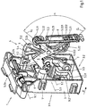
- Fig. 1 shows a perspective view of a flushing operation device 1 for installation in a cistern 2 of a toilet or urinal (not shown), which has a housing 3 with a front side 3.1 and a back side 3.2 and an actuating mechanism 4.
- the actuating mechanism 4 has inter alia a trigger lever 5, two independent auxiliary lever 9 and 9 'and two independent actuators 7 and 7', which are each connected to a flush button 2.2, on.
- FIG. 2 An actuation of one of the flush buttons 2.2, one of which is in Fig. 2 is shown schematically (for reasons of clarity, only one rinsing button is shown), causes a translational movement of mechanically connected to the respective rinsing button 2.2 actuator 7 or 7 '.
- the actuating elements 7 and 7 ' in turn act mechanically on the release lever 5, which is described below by way of example in the case of a translational movement of the lower illustrated actuator 7 (the operation of the other actuator 7' also acts on the trigger lever 5, but causes a other flushing volume).
- the auxiliary lever 9 is pivoted counterclockwise.
- the auxiliary lever 9 is pivotally mounted in the housing 3 about a parallel to the front 3.1 and 3.2 rear pivot axis 9.1 and mechanically connected via a projection 5.4 on the release lever 5. The same applies to the interaction of the actuating element 7 'with the auxiliary lever 9'. Emotional If the actuating element 7 'in the direction X from the front side 3.1 to the rear side 3.2 of the housing 3, the auxiliary lever 9' is pivoted counterclockwise about its pivot axis 9.1 '.
- the pivotal movement of the auxiliary lever 9 is transmitted via a projection of the release lever 5 5 on this.
- the pivoting movement of the auxiliary lever 9 ' is transmitted from the lower end of the lever 9.2' via a lower end 5.51 of the release lever 5 on this.
- the release lever 5 is also pivotally mounted in the housing 3 about a parallel to the front 3.1 and 3.2 rear pivot axis 5.1, wherein the pivot axis 5.1 of the release lever 5 parallel to the pivot axis 9.1 of the auxiliary lever 9 and parallel to the pivot axis 9.1 'of the auxiliary lever 9'.
- the release lever 5 has a lever section 5.2 extending from the pivot axis 5.1 to a first end 5.21.
- This lever section 5.2 has at a location remote from the pivot axis 5.1 point a hook-shaped receptacle 5.22 for mechanical connection with a flush valve 6, as shown in the Figures 2 and 3 is shown.
- the recording 5.22 shows how Fig. 1 shows, below a contact surface 5.221, which comes in mechanical connection with the purge valve 6 with a valve yoke 6.1 in contact.
- the contact area 5.221 is how Fig. 1 shows, to the right (facing away from the housing 3) side bounded by a projection 5.222 and the left (the housing 3) side by a side wall 5.223.
- the lever section 5.2 is substantially L-shaped, with a first section 5.2a of the lever section 5.2 extending from the pivot axis 5.1 to a kink 5.24 of the lever section 5.2 and a second section 5.2b from the kink point 5.24 to the first end 5.21.
- a pivoting movement of the release lever 5 in the counterclockwise direction causes the receptacle 5.22 pivots with and in a position vertically above the in Fig. 1 moved position shown.
- the Fig. 1 shown position is referred to as rest position in which the purge valve 6 is closed, while the (not shown) position or positions in the swung-out state is referred to as the trigger position in which the purge valve 6 is opened.
- the release lever 5 passes through a respective different maximum pivot angle between the rest position and the respective release position, which in turn corresponds to a particular flushing amount.
- the largest maximum swing angle leads to a large flush volume, the smaller maximum swing angle leads to a smaller flush volume.
- Maximum means that the swing angle has two these limiting end positions.
- the triggering lever 5 in the triggering position abuts a projection 9.2 on the auxiliary lever 9 and thus limits the maximum pivoting angle in the direction of the triggering position.
- the auxiliary lever comes into contact with the housing 3 or a projection (not shown) disposed thereon, which limits the pivoting angle in this direction.
- a comparable limitation of the maximum pivot angle for the case of actuation of the actuating element 7 'via stops is also conceivable.
- the release lever 5 also has a further lever portion 5.5, which extends from the pivot axis 5.1 to a second end of 5.51, which finds a stop in the housing 3 in the rest position.
- the flushing actuating device 1 can be both vertical ( Fig. 2 ) as well as horizontally ( Fig. 3 ) are arranged in the housing 2.1 of the cistern 2.
- the release lever 5 an additional arm 5.3.
- the arm 5.3 branches off from the extending from the pivot axis 5.1 to the first end of 5.21 lever section 5.2 and has at its end remote from the lever section 5.2 5.31 a loop-shaped receptacle 5.32 for mechanical connection with the purge valve 6.
- the connecting rod 8 serves to bridge the distance between the receiving eye 5.32 of the arm 5.3 and the purge valve 6, more precisely a valve lever 6.2, which is fixedly mounted on the valve body 6.3.
- the arm 5.3 is made in one piece together with the lever section 5.2 and the lever section 5.5, wherein these three elements together form the trigger lever 5.
- the release lever 5 is presently made of plastic.
- the arm 5.3 is arranged to the lever section 5.2 that several conditions are met.
- a first imaginary straight line G 1 which is perpendicular to the pivot axis 5.1 of the release lever 5 and both through the pivot axis 5.1 and centrally through the contact surface 5.221 of the receptacle 5.22, at an angle to a second imaginary straight line G 2 , in the same plane as the first imaginary straight line G 1 and passes both centrally through the receptacle 5.32 and centrally through the branch point 5.23.
- the branch point 5.23 is an imaginary surface which connects in the shortest possible way the arm-side surface of the lever section 5.2 to one side of the arm 5.3 with the arm-side surface to the other side of the arm 5.3.
- the smallest angle between the two straight lines G 1 and G 2 is in a range of 80 to 100 ° and is for example 90 °.
- the shortest distance between the pivot axis 5.1 and the center of the contact surface 5.221 of the receptacle 5.22 for example, in a range of 90 to 110% of the shortest distance between the pivot axis 5.1 and the center of the receptacle 5.32, the two distances are the same example.
- the Spülungsbet2011 Trental Stapéutica 1 is used as a structural unit, that is, as a whole, in a Spülkastengeophuse 2.1 a cistern 2.
- Fig. 2 shows an arrangement with a cistern 2 for a toilet or urinal, arranged with a Spippoboxgeophuse 2.1 flush valve 6 and with a Spülungsbetuschistsvortechnisch 1 of the type described above, which is also located inside the Spülkastengephases 2.1.
- the cistern housing 2.1 is filled with rinse water and has a front side to 2.11, which is turned in the intended mounted state of the cistern 2 to the room, and a top 2.12, which is turned in the intended mounted state of the cistern 2 to the ceiling of the room.
- the cistern 2 also has two flush buttons 2.2, of which schematically in Fig. 2 only one is shown. Both rinsing buttons 2.2 are accessible in the intended mounted state of the cistern 2 from the outside, that is operable.
- the orientation of the Spülungsbetuschistsvorraum 1 is selected so that the at least one rinsing button 2.2 is located on the front side of the Spippokastengephaseuses 2.1 2.1, wherein the front 3.1 of the housing 3 of the Spülungsbetuschistsvortechnisch 1 in the same direction as the front side of the Spülkastengephaseuses 2.1 2.1 2.1 and wherein the flushing valve 6 is mechanically connected to the receptacle 5.22 of the lever section 5.2 of the release lever 5.
Landscapes
- Engineering & Computer Science (AREA)
- Mechanical Engineering (AREA)
- Aviation & Aerospace Engineering (AREA)
- Health & Medical Sciences (AREA)
- Life Sciences & Earth Sciences (AREA)
- Hydrology & Water Resources (AREA)
- Public Health (AREA)
- Water Supply & Treatment (AREA)
- Sanitary Device For Flush Toilet (AREA)
Claims (10)
- Dispositif d'actionnement du rinçage (1) à intégrer dans une chasse d'eau (2) d'une toilette ou d'un urinoir, comprenant- un boitier (3) présentant une face avant (3.1) et une face arrière (3.2), et- un mécanisme d'actionnement (4) contenant au moins- un levier de déclenchement (5), qui est disposé sur le boitier (3) de manière pivotante par un axe de pivot (5.1) et qui présente un segment de levier (5.2) s'étendant de l'axe de pivot (5.1) à une première extrémité (5.21), où le segment de levier (5.2) présente en une position distante de l'axe de pivot (5.1), un agencement (5.22) avec une surface de contact (5.221) pour le lien mécanique avec une vanne de rinçage (6), et- au moins un élément d'actionnement (7,7'), qui est mobile dans le boitier (3) et relié mécaniquement au levier de déclenchement (5),où un bras (5.3) part du segment de levier (5.2) s'étendant de l'axe de pivot (5.1) à la première extrémité (5.21) du levier de déclenchement (5) en un point d'embranchement (5.23), lequel bras (5.3) présente sur son extrémité (5.31) opposée au segment de levier (5.2), un agencement (5.32) pour la liaison mécanique à une vanne de rinçage (6),
caractérisé en ce que dans l'agencement (5.32) du bras (5.3), un dispositif de liaison (8) pour la liaison mécanique à la vanne de rinçage (6) est disposé de manière pivotante. - Dispositif d'actionnement du rinçage (1) selon la revendication 1, caractérisé en ce que le bras (5.3) et le segment de levier (5.2) s'étendant de l'axe de pivot (5.1) à la première extrémité (5.21) sont d'un seul tenant.
- Dispositif d'actionnement du rinçage (1) selon la revendication 1 ou 2, caractérisé en ce que une première droite imaginaire (G1), qui s'étend perpendiculairement à l'axe de pivot (5.1) du levier de déclenchement (5), et non seulement par l'axe de pivot (5.1) du levier de déclenchement (5), mais aussi au centre de la surface de contact (5.221) de l'agencement (5.22) du segment de levier (5.2), présente un angle avec une deuxième droite imaginaire (G2), qui s'étend dans le même plan que la première droite imaginaire (G1) et non seulement au centre de l'agencement (5.2) du bras (5.3), mais également au centre du point d'embranchement (5.23), où le plus petit angle (α) entre les droites (G1, G2) se situe dans un intervalle allant de 45 à 135°, de préférence de 65 à 115°, en particulier de 80 à 100°, et en particulier s'élève à 90°.
- Dispositif d'actionnement du rinçage (1) selon l'une des revendications précédentes, caractérisé en ce que la plus courte distance entre l'axe de pivot (5.1) du levier de déclenchement (5) et le centre de la surface de contact (5.221) de l'agencement (5.22) du segment de levier (5.2) se situe dans l'intervalle allant de 70 à 130%, de préférence de 80 à 120%, en particulier de 90 à 110%, en particulier à 100% de la distance la plus courte entre l'axe de pivot (5.1) du levier de déclenchement (5) et le centre de l'agencement (5.32) du bras (5.3).
- Dispositif d'actionnement du rinçage (1) selon l'une des revendications précédentes, caractérisé en ce que le dispositif de liaison (8) est une tige ou chaine de liaison, en particulier une tige de traction (8).
- Dispositif d'actionnement du rinçage (1) selon l'une des revendications précédentes, caractérisé en ce que le dispositif de liaison (8) peut être fixé au levier de déclenchement (5), en particulier à la première extrémité (5.21) du segment de levier (5.2), en particulier par une liaison par adhérence et/ou par blocage.
- Dispositif d'actionnement du rinçage (1) selon l'une des revendications précédentes, caractérisé en ce que le dispositif d'actionnement du rinçage (1) forme une unité structurelle préalablement montée.
- Système- présentant une chasse d'eau (2) pour une toilette ou un urinoir, comprenant- un boitier de chasse d'eau (2.1), pouvant être rempli de l'eau de rinçage, qui présente une face avant (2.11) et une face supérieure (2.12), et- au moins un bouton de rinçage (2.2), qui est relié mécaniquement au boitier de chasse d'eau (2.1) et ce par l'extérieur, de manière accessible,- une vanne de rinçage (6) disposée dans le boitier de chasse d'eau (2.1), et- un dispositif d'actionnement du rinçage (1) selon l'une des revendications précédentes, qui est agencé à l'intérieur du boitier de chasse d'eau (2.1),où le au moins un bouton de rinçage (2.2) est relié mécaniquement au au moins un élément d'actionnement (7,7') du mécanisme d'actionnement (4) du dispositif d'actionnement du rinçage (1).
- Système selon la revendication 8, caractérisé en ce que le au moins un bouton de rinçage (2.2) est agencé sur la face avant (2.11) du boitier de chasse d'eau (2.1), où la face avant (3.1) du boitier (3) du dispositif d'actionnement du rinçage (1) est dans la même direction que la face avant (2.11) du boitier de chasse d'eau (2.1) et où la vanne de rinçage (6) est reliée mécaniquement à l'agencement (5.22) du segment de levier (5.2) du levier de déclenchement (5).
- Système selon la revendication 8, caractérisé en ce que le au moins un bouton de rinçage (2.2) est agencé sur la face supérieure (2.12) du boitier de chasse d'eau (2.1), où la face avant (3.1) du boitier (3) du dispositif d'actionnement du rinçage (1) est dans la même direction que la face supérieure (2.12) du boitier de chasse d'eau (2.1) et où la vanne de rinçage (6) est reliée mécaniquement à l'agencement (5.23) du bras (5.3) du levier de déclenchement (5) ou au dispositif de liaison (8).
Applications Claiming Priority (1)
| Application Number | Priority Date | Filing Date | Title |
|---|---|---|---|
| DE202014001764.6U DE202014001764U1 (de) | 2014-02-28 | 2014-02-28 | Spülungsbetätigungsvorrichtung und Anordnung mit einem Spülkasten für ein Klosett oder Urinal |
Publications (2)
| Publication Number | Publication Date |
|---|---|
| EP2913449A1 EP2913449A1 (fr) | 2015-09-02 |
| EP2913449B1 true EP2913449B1 (fr) | 2018-05-16 |
Family
ID=51987009
Family Applications (1)
| Application Number | Title | Priority Date | Filing Date |
|---|---|---|---|
| EP14194230.0A Active EP2913449B1 (fr) | 2014-02-28 | 2014-11-21 | Dispositif d'actionnement du rinçage et système équipé d'une chasse d'eau pour un toilette ou un urinoir |
Country Status (3)
| Country | Link |
|---|---|
| EP (1) | EP2913449B1 (fr) |
| DE (1) | DE202014001764U1 (fr) |
| PT (1) | PT2913449T (fr) |
Family Cites Families (8)
| Publication number | Priority date | Publication date | Assignee | Title |
|---|---|---|---|---|
| FR2739116B1 (fr) * | 1995-09-21 | 1997-10-31 | Allia | Reservoir de chasse a encastrer a commande par le dessus ou en facade |
| DE29812224U1 (de) * | 1997-09-24 | 1998-10-08 | Geberit Technik Ag, Jona | Unterputzspülkasten |
| DE19914841A1 (de) * | 1999-01-27 | 2000-08-24 | Friatec Ag | Vorrichtung zur Betätigung des Ventils eines Spülkastens |
| DE20203670U1 (de) * | 2002-03-07 | 2003-07-17 | Franz Viegener II GmbH & Co. KG, 57439 Attendorn | Spülkasten |
| ITMI20040044A1 (it) * | 2004-01-15 | 2004-04-15 | Valsir Spa | Dispositivo di azionamento dello scarico in una cassetta di risciacquo |
| PL1593787T3 (pl) * | 2004-05-05 | 2017-03-31 | Geberit Service Ab | Mechanizm do spłukiwania urządzenia toaletowego |
| DE502005004831D1 (de) * | 2005-12-06 | 2008-09-04 | Geberit Technik Ag | Vorrichtung zur Betätigung des Ablaufventils eines Spülkastens |
| CN201395837Y (zh) * | 2009-05-07 | 2010-02-03 | 上海科勒电子科技有限公司 | 手自动一体冲水驱动装置 |
-
2014
- 2014-02-28 DE DE202014001764.6U patent/DE202014001764U1/de not_active Expired - Lifetime
- 2014-11-21 EP EP14194230.0A patent/EP2913449B1/fr active Active
- 2014-11-21 PT PT141942300T patent/PT2913449T/pt unknown
Non-Patent Citations (1)
| Title |
|---|
| None * |
Also Published As
| Publication number | Publication date |
|---|---|
| DE202014001764U1 (de) | 2015-05-29 |
| PT2913449T (pt) | 2018-06-15 |
| EP2913449A1 (fr) | 2015-09-02 |
Similar Documents
| Publication | Publication Date | Title |
|---|---|---|
| DE102005014137B4 (de) | Türverriegelungssystem | |
| DE102012111397B4 (de) | Motorhaubenverriegelungsvorrichtung mit Zwei-Stufen-Führung für ein Fahrzeug | |
| DE102010043658B4 (de) | Türschlosskonstruktion | |
| DE102011101876A1 (de) | Verriegelungssystem für einen Fahrzeugsitz, insbesondere Kraftfahrzeugsitz, zur Verriegelung an einer Fahrzeugstruktur eines Fahrzeugs | |
| DE10036968A1 (de) | Sitzlehnenverriegelungsvorrichtung | |
| EP3147433B1 (fr) | Serrure de véhicule automobile | |
| DE102018132371B4 (de) | Mechanische Vorrichtung zur gekoppelten Ver- und Entriegelung einer ersten Tür und einer der ersten Tür gegenüberliegenden zweiten Tür eines Schaltschranks sowie Schaltschrank mit einer solchen mechanischen Vorrichtung | |
| DE10216439B4 (de) | Hilfsschalter | |
| DE102009050077B4 (de) | Fahrzeugschloss | |
| EP2388379B1 (fr) | Dispositif d'actionnement pour une chasse d'eau | |
| DE102009002419B4 (de) | Tür mit mindestens einem Betätigungselement und mindestens einem Riegel | |
| DE102004037827B4 (de) | Elektrischer Türöffner | |
| EP3098357A1 (fr) | Dispositif d'actionnement de soupape de vidange d'un réservoir de chasse | |
| EP2913449B1 (fr) | Dispositif d'actionnement du rinçage et système équipé d'une chasse d'eau pour un toilette ou un urinoir | |
| EP3882407B1 (fr) | Arrangement de réservoir de chasse d'eau | |
| EP2582000B1 (fr) | Boîtier d'un appareil électrique ou électronique | |
| DE102007048245B3 (de) | Rastelement sowie Verrastungsanordnung | |
| EP3064666B1 (fr) | WC avec bidet | |
| EP1088942B1 (fr) | Dispositif d'actionnement | |
| EP2322744A1 (fr) | Serrure, serrure à crochet pivotant et système de verrouillage, notamment pour le verrouillage à plusieurs points d'une porte ou d'une fenêtre | |
| DE10218526B4 (de) | Schaltgerät | |
| EP1208272B1 (fr) | Dispositif d'actionnement pour armature d'ecoulement d'un reservoir de chasse | |
| EP4302024A1 (fr) | Pompe à chaleur | |
| EP2489795B1 (fr) | Plaque d'actionnement pour déclenchement de rinçage | |
| EP2852014B1 (fr) | Appareil de commande et de signalisation doté d'un montage encastré en façade |
Legal Events
| Date | Code | Title | Description |
|---|---|---|---|
| PUAI | Public reference made under article 153(3) epc to a published international application that has entered the european phase |
Free format text: ORIGINAL CODE: 0009012 |
|
| AK | Designated contracting states |
Kind code of ref document: A1 Designated state(s): AL AT BE BG CH CY CZ DE DK EE ES FI FR GB GR HR HU IE IS IT LI LT LU LV MC MK MT NL NO PL PT RO RS SE SI SK SM TR |
|
| AX | Request for extension of the european patent |
Extension state: BA ME |
|
| 17P | Request for examination filed |
Effective date: 20151028 |
|
| RBV | Designated contracting states (corrected) |
Designated state(s): AL AT BE BG CH CY CZ DE DK EE ES FI FR GB GR HR HU IE IS IT LI LT LU LV MC MK MT NL NO PL PT RO RS SE SI SK SM TR |
|
| RAP1 | Party data changed (applicant data changed or rights of an application transferred) |
Owner name: VIEGA TECHNOLOGY GMBH & CO. KG |
|
| GRAP | Despatch of communication of intention to grant a patent |
Free format text: ORIGINAL CODE: EPIDOSNIGR1 |
|
| RIC1 | Information provided on ipc code assigned before grant |
Ipc: E03D 5/02 20060101AFI20171128BHEP |
|
| INTG | Intention to grant announced |
Effective date: 20171221 |
|
| RIN1 | Information on inventor provided before grant (corrected) |
Inventor name: DROSTE, STEFAN Inventor name: MANEGOLD, CHRISTOPH Inventor name: FIEDLER, SASCHA |
|
| GRAS | Grant fee paid |
Free format text: ORIGINAL CODE: EPIDOSNIGR3 |
|
| GRAA | (expected) grant |
Free format text: ORIGINAL CODE: 0009210 |
|
| AK | Designated contracting states |
Kind code of ref document: B1 Designated state(s): AL AT BE BG CH CY CZ DE DK EE ES FI FR GB GR HR HU IE IS IT LI LT LU LV MC MK MT NL NO PL PT RO RS SE SI SK SM TR |
|
| REG | Reference to a national code |
Ref country code: GB Ref legal event code: FG4D Free format text: NOT ENGLISH |
|
| REG | Reference to a national code |
Ref country code: CH Ref legal event code: EP |
|
| REG | Reference to a national code |
Ref country code: IE Ref legal event code: FG4D Free format text: LANGUAGE OF EP DOCUMENT: GERMAN |
|
| REG | Reference to a national code |
Ref country code: DE Ref legal event code: R096 Ref document number: 502014008266 Country of ref document: DE |
|
| REG | Reference to a national code |
Ref country code: CH Ref legal event code: NV Representative=s name: SCHMAUDER AND PARTNER AG PATENT- UND MARKENANW, CH Ref country code: AT Ref legal event code: REF Ref document number: 999697 Country of ref document: AT Kind code of ref document: T Effective date: 20180615 Ref country code: PT Ref legal event code: SC4A Ref document number: 2913449 Country of ref document: PT Date of ref document: 20180615 Kind code of ref document: T Free format text: AVAILABILITY OF NATIONAL TRANSLATION Effective date: 20180607 |
|
| REG | Reference to a national code |
Ref country code: NL Ref legal event code: MP Effective date: 20180516 |
|
| REG | Reference to a national code |
Ref country code: LT Ref legal event code: MG4D |
|
| PG25 | Lapsed in a contracting state [announced via postgrant information from national office to epo] |
Ref country code: SE Free format text: LAPSE BECAUSE OF FAILURE TO SUBMIT A TRANSLATION OF THE DESCRIPTION OR TO PAY THE FEE WITHIN THE PRESCRIBED TIME-LIMIT Effective date: 20180516 Ref country code: LT Free format text: LAPSE BECAUSE OF FAILURE TO SUBMIT A TRANSLATION OF THE DESCRIPTION OR TO PAY THE FEE WITHIN THE PRESCRIBED TIME-LIMIT Effective date: 20180516 Ref country code: ES Free format text: LAPSE BECAUSE OF FAILURE TO SUBMIT A TRANSLATION OF THE DESCRIPTION OR TO PAY THE FEE WITHIN THE PRESCRIBED TIME-LIMIT Effective date: 20180516 Ref country code: NO Free format text: LAPSE BECAUSE OF FAILURE TO SUBMIT A TRANSLATION OF THE DESCRIPTION OR TO PAY THE FEE WITHIN THE PRESCRIBED TIME-LIMIT Effective date: 20180816 Ref country code: BG Free format text: LAPSE BECAUSE OF FAILURE TO SUBMIT A TRANSLATION OF THE DESCRIPTION OR TO PAY THE FEE WITHIN THE PRESCRIBED TIME-LIMIT Effective date: 20180816 Ref country code: FI Free format text: LAPSE BECAUSE OF FAILURE TO SUBMIT A TRANSLATION OF THE DESCRIPTION OR TO PAY THE FEE WITHIN THE PRESCRIBED TIME-LIMIT Effective date: 20180516 |
|
| PG25 | Lapsed in a contracting state [announced via postgrant information from national office to epo] |
Ref country code: NL Free format text: LAPSE BECAUSE OF FAILURE TO SUBMIT A TRANSLATION OF THE DESCRIPTION OR TO PAY THE FEE WITHIN THE PRESCRIBED TIME-LIMIT Effective date: 20180516 Ref country code: RS Free format text: LAPSE BECAUSE OF FAILURE TO SUBMIT A TRANSLATION OF THE DESCRIPTION OR TO PAY THE FEE WITHIN THE PRESCRIBED TIME-LIMIT Effective date: 20180516 Ref country code: LV Free format text: LAPSE BECAUSE OF FAILURE TO SUBMIT A TRANSLATION OF THE DESCRIPTION OR TO PAY THE FEE WITHIN THE PRESCRIBED TIME-LIMIT Effective date: 20180516 Ref country code: HR Free format text: LAPSE BECAUSE OF FAILURE TO SUBMIT A TRANSLATION OF THE DESCRIPTION OR TO PAY THE FEE WITHIN THE PRESCRIBED TIME-LIMIT Effective date: 20180516 Ref country code: GR Free format text: LAPSE BECAUSE OF FAILURE TO SUBMIT A TRANSLATION OF THE DESCRIPTION OR TO PAY THE FEE WITHIN THE PRESCRIBED TIME-LIMIT Effective date: 20180817 |
|
| PG25 | Lapsed in a contracting state [announced via postgrant information from national office to epo] |
Ref country code: DK Free format text: LAPSE BECAUSE OF FAILURE TO SUBMIT A TRANSLATION OF THE DESCRIPTION OR TO PAY THE FEE WITHIN THE PRESCRIBED TIME-LIMIT Effective date: 20180516 Ref country code: PL Free format text: LAPSE BECAUSE OF FAILURE TO SUBMIT A TRANSLATION OF THE DESCRIPTION OR TO PAY THE FEE WITHIN THE PRESCRIBED TIME-LIMIT Effective date: 20180516 Ref country code: EE Free format text: LAPSE BECAUSE OF FAILURE TO SUBMIT A TRANSLATION OF THE DESCRIPTION OR TO PAY THE FEE WITHIN THE PRESCRIBED TIME-LIMIT Effective date: 20180516 Ref country code: SK Free format text: LAPSE BECAUSE OF FAILURE TO SUBMIT A TRANSLATION OF THE DESCRIPTION OR TO PAY THE FEE WITHIN THE PRESCRIBED TIME-LIMIT Effective date: 20180516 Ref country code: CZ Free format text: LAPSE BECAUSE OF FAILURE TO SUBMIT A TRANSLATION OF THE DESCRIPTION OR TO PAY THE FEE WITHIN THE PRESCRIBED TIME-LIMIT Effective date: 20180516 Ref country code: RO Free format text: LAPSE BECAUSE OF FAILURE TO SUBMIT A TRANSLATION OF THE DESCRIPTION OR TO PAY THE FEE WITHIN THE PRESCRIBED TIME-LIMIT Effective date: 20180516 |
|
| REG | Reference to a national code |
Ref country code: DE Ref legal event code: R097 Ref document number: 502014008266 Country of ref document: DE |
|
| PG25 | Lapsed in a contracting state [announced via postgrant information from national office to epo] |
Ref country code: SM Free format text: LAPSE BECAUSE OF FAILURE TO SUBMIT A TRANSLATION OF THE DESCRIPTION OR TO PAY THE FEE WITHIN THE PRESCRIBED TIME-LIMIT Effective date: 20180516 |
|
| PLBE | No opposition filed within time limit |
Free format text: ORIGINAL CODE: 0009261 |
|
| STAA | Information on the status of an ep patent application or granted ep patent |
Free format text: STATUS: NO OPPOSITION FILED WITHIN TIME LIMIT |
|
| 26N | No opposition filed |
Effective date: 20190219 |
|
| PG25 | Lapsed in a contracting state [announced via postgrant information from national office to epo] |
Ref country code: SI Free format text: LAPSE BECAUSE OF FAILURE TO SUBMIT A TRANSLATION OF THE DESCRIPTION OR TO PAY THE FEE WITHIN THE PRESCRIBED TIME-LIMIT Effective date: 20180516 |
|
| GBPC | Gb: european patent ceased through non-payment of renewal fee |
Effective date: 20181121 |
|
| PG25 | Lapsed in a contracting state [announced via postgrant information from national office to epo] |
Ref country code: LU Free format text: LAPSE BECAUSE OF NON-PAYMENT OF DUE FEES Effective date: 20181121 Ref country code: MC Free format text: LAPSE BECAUSE OF FAILURE TO SUBMIT A TRANSLATION OF THE DESCRIPTION OR TO PAY THE FEE WITHIN THE PRESCRIBED TIME-LIMIT Effective date: 20180516 |
|
| REG | Reference to a national code |
Ref country code: BE Ref legal event code: MM Effective date: 20181130 |
|
| REG | Reference to a national code |
Ref country code: IE Ref legal event code: MM4A |
|
| PG25 | Lapsed in a contracting state [announced via postgrant information from national office to epo] |
Ref country code: IE Free format text: LAPSE BECAUSE OF NON-PAYMENT OF DUE FEES Effective date: 20181121 Ref country code: FR Free format text: LAPSE BECAUSE OF NON-PAYMENT OF DUE FEES Effective date: 20181130 |
|
| PG25 | Lapsed in a contracting state [announced via postgrant information from national office to epo] |
Ref country code: AL Free format text: LAPSE BECAUSE OF FAILURE TO SUBMIT A TRANSLATION OF THE DESCRIPTION OR TO PAY THE FEE WITHIN THE PRESCRIBED TIME-LIMIT Effective date: 20180516 Ref country code: BE Free format text: LAPSE BECAUSE OF NON-PAYMENT OF DUE FEES Effective date: 20181130 |
|
| PG25 | Lapsed in a contracting state [announced via postgrant information from national office to epo] |
Ref country code: GB Free format text: LAPSE BECAUSE OF NON-PAYMENT OF DUE FEES Effective date: 20181121 |
|
| PG25 | Lapsed in a contracting state [announced via postgrant information from national office to epo] |
Ref country code: MT Free format text: LAPSE BECAUSE OF FAILURE TO SUBMIT A TRANSLATION OF THE DESCRIPTION OR TO PAY THE FEE WITHIN THE PRESCRIBED TIME-LIMIT Effective date: 20180516 |
|
| PG25 | Lapsed in a contracting state [announced via postgrant information from national office to epo] |
Ref country code: TR Free format text: LAPSE BECAUSE OF FAILURE TO SUBMIT A TRANSLATION OF THE DESCRIPTION OR TO PAY THE FEE WITHIN THE PRESCRIBED TIME-LIMIT Effective date: 20180516 |
|
| PG25 | Lapsed in a contracting state [announced via postgrant information from national office to epo] |
Ref country code: CY Free format text: LAPSE BECAUSE OF FAILURE TO SUBMIT A TRANSLATION OF THE DESCRIPTION OR TO PAY THE FEE WITHIN THE PRESCRIBED TIME-LIMIT Effective date: 20180516 Ref country code: MK Free format text: LAPSE BECAUSE OF NON-PAYMENT OF DUE FEES Effective date: 20180516 Ref country code: HU Free format text: LAPSE BECAUSE OF FAILURE TO SUBMIT A TRANSLATION OF THE DESCRIPTION OR TO PAY THE FEE WITHIN THE PRESCRIBED TIME-LIMIT; INVALID AB INITIO Effective date: 20141121 |
|
| PG25 | Lapsed in a contracting state [announced via postgrant information from national office to epo] |
Ref country code: IS Free format text: LAPSE BECAUSE OF FAILURE TO SUBMIT A TRANSLATION OF THE DESCRIPTION OR TO PAY THE FEE WITHIN THE PRESCRIBED TIME-LIMIT Effective date: 20180916 |
|
| REG | Reference to a national code |
Ref country code: AT Ref legal event code: MM01 Ref document number: 999697 Country of ref document: AT Kind code of ref document: T Effective date: 20191121 |
|
| PG25 | Lapsed in a contracting state [announced via postgrant information from national office to epo] |
Ref country code: AT Free format text: LAPSE BECAUSE OF NON-PAYMENT OF DUE FEES Effective date: 20191121 |
|
| PGFP | Annual fee paid to national office [announced via postgrant information from national office to epo] |
Ref country code: PT Payment date: 20211018 Year of fee payment: 8 |
|
| PGFP | Annual fee paid to national office [announced via postgrant information from national office to epo] |
Ref country code: IT Payment date: 20211124 Year of fee payment: 8 |
|
| PG25 | Lapsed in a contracting state [announced via postgrant information from national office to epo] |
Ref country code: PT Free format text: LAPSE BECAUSE OF NON-PAYMENT OF DUE FEES Effective date: 20230522 |
|
| PG25 | Lapsed in a contracting state [announced via postgrant information from national office to epo] |
Ref country code: IT Free format text: LAPSE BECAUSE OF NON-PAYMENT OF DUE FEES Effective date: 20221121 |
|
| REG | Reference to a national code |
Ref country code: CH Ref legal event code: U11 Free format text: ST27 STATUS EVENT CODE: U-0-0-U10-U11 (AS PROVIDED BY THE NATIONAL OFFICE) Effective date: 20251201 |
|
| PGFP | Annual fee paid to national office [announced via postgrant information from national office to epo] |
Ref country code: DE Payment date: 20251120 Year of fee payment: 12 |
|
| PGFP | Annual fee paid to national office [announced via postgrant information from national office to epo] |
Ref country code: CH Payment date: 20251201 Year of fee payment: 12 |