EP2913450A1 - Steuerungsplattenanordnung eines spültanks und anordnungssystem und verfahren dafür - Google Patents
Steuerungsplattenanordnung eines spültanks und anordnungssystem und verfahren dafür Download PDFInfo
- Publication number
- EP2913450A1 EP2913450A1 EP15398001.6A EP15398001A EP2913450A1 EP 2913450 A1 EP2913450 A1 EP 2913450A1 EP 15398001 A EP15398001 A EP 15398001A EP 2913450 A1 EP2913450 A1 EP 2913450A1
- Authority
- EP
- European Patent Office
- Prior art keywords
- counterplate
- support
- buttons
- button
- plate assembly
- Prior art date
- Legal status (The legal status is an assumption and is not a legal conclusion. Google has not performed a legal analysis and makes no representation as to the accuracy of the status listed.)
- Granted
Links
- 238000011010 flushing procedure Methods 0.000 title claims abstract description 22
- 238000000034 method Methods 0.000 title claims description 8
- 230000008878 coupling Effects 0.000 claims description 23
- 238000010168 coupling process Methods 0.000 claims description 23
- 238000005859 coupling reaction Methods 0.000 claims description 23
- 230000000712 assembly Effects 0.000 description 6
- 238000000429 assembly Methods 0.000 description 6
- 230000002093 peripheral effect Effects 0.000 description 3
- 230000008859 change Effects 0.000 description 2
- 238000007689 inspection Methods 0.000 description 2
- 238000004519 manufacturing process Methods 0.000 description 2
- 241001481828 Glyptocephalus cynoglossus Species 0.000 description 1
- 239000002421 finishing Substances 0.000 description 1
- 230000007246 mechanism Effects 0.000 description 1
- 238000012986 modification Methods 0.000 description 1
- 230000004048 modification Effects 0.000 description 1
- XLYOFNOQVPJJNP-UHFFFAOYSA-N water Substances O XLYOFNOQVPJJNP-UHFFFAOYSA-N 0.000 description 1
Images



Classifications
-
- E—FIXED CONSTRUCTIONS
- E03—WATER SUPPLY; SEWERAGE
- E03D—WATER-CLOSETS OR URINALS WITH FLUSHING DEVICES; FLUSHING VALVES THEREFOR
- E03D5/00—Special constructions of flushing devices, e.g. closed flushing system
- E03D5/02—Special constructions of flushing devices, e.g. closed flushing system operated mechanically or hydraulically (or pneumatically) also details such as push buttons, levers and pull-card therefor
- E03D5/028—Pusher plates and actuating mechanisms for built-in cisterns
-
- E—FIXED CONSTRUCTIONS
- E03—WATER SUPPLY; SEWERAGE
- E03D—WATER-CLOSETS OR URINALS WITH FLUSHING DEVICES; FLUSHING VALVES THEREFOR
- E03D5/00—Special constructions of flushing devices, e.g. closed flushing system
- E03D5/02—Special constructions of flushing devices, e.g. closed flushing system operated mechanically or hydraulically (or pneumatically) also details such as push buttons, levers and pull-card therefor
Definitions
- the present invention relates to a control plate assembly of a flushing tank, and to a system and a method for assembling control plate assemblies of flushing tanks.
- a control plate assembly of a walled or recessed flushing tank generally comprises a mounting counterplate, shaped as a frame and which is fixed to the wall or to a front wall of the tank, about an inspection opening which allows to access the interior of the tank and the drain valve accommodated therein; and a cover plate, detachably fixed to the counterplate and provided with one or two control buttons which cooperate with actuating members of the drain valve.
- buttons are usually hinged to the plate, while the actuating members of the drain valve are supported by the counterplate and arranged through the inspection opening.
- the plate and its buttons are the visible components of the control plate assembly and take on various shapes. Therefore, multiple different plates with different buttons are manufactured, essentially for aesthetic reasons.
- Each plate generally requires a specifically designed counterplate, because each plate is provided with buttons with different shapes and sizes and placed in different positions, and as a result the counterplate must support the actuating members in such a position as to interact with the buttons carried by the plate.
- the present invention relates to a control plate assembly of a flushing tank as defined in essential terms in appended claim 1.
- the present invention also relates to a system and a method for assembling a control plate assembly of a flushing tank as defined in essential terms in appended claims 7 and 8, respectively.
- control plate assembly of the invention is simple and cost-effective to be manufactured and assembled, and is also completely efficient and reliable.
- control plate assembly of the invention is manufactured with an assembly system and method which allow a variety of different control plate assemblies (in particular, having different aesthetic appearance) to be manufactured in a simple and affordable manner, with a reduced number of different components.
- a control plate assembly 1 of a flushing tank (not shown) comprises a mounting counterplate 2; a cover plate 3, joined to the counterplate by a releasable connecting system 4; and at least one control button 5 cooperating, in use, with an actuating member 6 of a drain valve (not shown) of the flushing tank.
- control plate assembly 1 comprises two control buttons 5 cooperating, in use, with respective actuating members 6 of the drain valve for actuating different flushing modes, namely for actuating a complete flush or a partial flush of the water contained in the flushing tank selectively.
- counterplate 2 comprises a frame 7, for example substantially rectangular and consisting of two pairs of substantially perpendicular sides 8, 9; for example, in use (i.e. when the control plate assembly 1 is mounted on a flushing tank), the frame has one upper horizontal side 8, one lower horizontal side 8, and two vertical sides 9.
- Frame 9 has an inner peripheral edge 10, which delimits a middle opening 11, and an outer peripheral edge 12.
- the counterplate 2 comprises ribs 14a, 14b which project into the opening 11 from edge 10.
- counterplate 2 comprises a first pair of (vertical) ribs 14a, which connect the opposite sides 8, and a second pair of (horizontal) ribs 14b, which connect respective sides 9 with a rib 14a.
- the counterplate 2 is provided with fastening members 16 for fixing the counterplate 2 to the flushing tank; for example, the fastening members 16 comprise a pair of fastening seats 17 formed on the counterplate 2 and a pair of screws 18 which engage the seats 17 and respective further fastening seats (not shown) on the tank (or on a component fixed to the tank).
- the fastening members 16 comprise a pair of fastening seats 17 formed on the counterplate 2 and a pair of screws 18 which engage the seats 17 and respective further fastening seats (not shown) on the tank (or on a component fixed to the tank).
- the seats 17 are obtained on respective portions 19 of counterplate 2, in particular of the ribs 14b, which project into the opening 11 from edge 10.
- the screws 18 comprise respective heads 20, which axially engage the seats 17, and respective threaded rods 21, which project from the heads 20 and cross the seats 17 to engage the fastening seats on the tank.
- the counterplate 2 is provided with supports 22 for the actuating members 6.
- each support 22 is defined by respective portions 23 of counterplate 2, for example of the ribs 14a, which project into the opening 11 from edge 10; each support 22 has a support seat 24, defined by a through hole obtained in portion 23 and which accommodates an actuating member 6.
- Each actuating member 6 comprises, for example, a rod 25 which extends from support 22 and engages an element of an actuation mechanism of the drain valve (known and not shown for simplicity); and a head 26, which protrudes from the support seat 24 towards plate 3 to cooperate with a button 5.
- Plate 3 may have various shapes and aesthetic finishings.
- Plate 3 generally comprises a front wall 27 and a peripheral edge 28 which surrounds the outer edge 12 of counterplate 2.
- Plate 3 has at least one window 29, formed in a through manner through the front wall 27.
- the connecting system 4 generally comprises coupling teeth which engage respective seats, carried by counterplate 2 and by plate 3, respectively, or vice versa; and a releasable locking element, spring-loaded and mounted on the counterplate for coupling the plate.
- buttons 5 are hinged to counterplate 2 via respective supports 30 fixed to the counterplate 2.
- Each button 5 extends between a root end 31, hinged to the respective support 30, and a free end 32, opposite to the root end 31 and provided with a driving portion 33, inserted into window 29 so as to be operable by a user through window 29.
- a connecting portion 34 connects the driving portion 33 to the root end 31.
- Each button 5 is joined to the respective support 30 via a hinge releasable coupling device 35, so that button 5 is detachable from support 30.
- the hinge releasable coupling device 35 comprises a pair of aligned pins 36 and a pair of rotation seats 37, formed on button 5 and on support 30, respectively, or vice versa and defining a rotation axis R of button 5 with respect to support 30; the seats 37 are shaped so as to receive the pins 36, which are snap-insertable into the seats 37; button 5 rotates with respect to support 30 about the rotation axis R and is restrained to support 30 transversely and parallel to the rotation axis R.
- Support 30 has an elongated base body 38 along a longitudinal axis A parallel to the rotation axis R (or coincident therewith).
- Support 30 is provided with a stop element 39 which projects from the base body 38 and cooperates in abutment against a contact portion 40 of button 5 to limit the rotation of button 5.
- buttons 5 and supports 30 advantageously consist of respective monolithic pieces.
- the supports 30 are detachable supports, insertable into respective coupling seats 41, 42 formed on the counterplate 2.
- Each support 30 is detachably attachable to a coupling seat 41, 42 (and therefore to counterplate 2), via releasable fastening elements 43, 44 formed on support 30 and on counterplate 2, respectively, and cooperating together to restrain support 30 to counterplate 2 integrally in the coupling seat 41, 42.
- the counterplate 2 is provided with a plurality of coupling seats 41, 42, formed on the counterplate 2 along the edge 10, namely along at least two perpendicular sides 8, 9 of counterplate 2.
- Each seat 41, 42 is shaped so as to receive a support 30, attachable to seat 41, 42 via the fastening elements 43, 44.
- the supports 30 of the two buttons 5 are advantageously equal, as well as all the seats 41, 42; the supports 30 are thus interchangeable in the seats 41, 42.
- counterplate 2 is provided with at least a first coupling seat 41 and a second coupling seat 42, arranged on respective sides 8, 9 perpendicular to counterplate 2.
- the counterplate 2 is provided witch a pair of first coupling seats 41, placed side-by-side on the upper horizontal side 8 of counterplate 2; and with a pair of second coupling seats 42, placed on respective opposite vertical sides 9 of counterplate 2.
- Each button 5 is selectively attachable to a coupling seat 41, 42, via support 30, so as to rotate about the rotation axis (R) of the corresponding support 30.
- buttons 5 are selectively attachable either to seats 41 or seats 42.
- buttons 5 are mounted in the seats 41, as diagrammatically shown in figure 5 , the buttons 5 are arranged side-by-side and have horizontal rotation axes R (parallel and coincident, i.e. they have a common rotation axis).
- buttons 5 are mounted in the seats 42, as diagrammatically shown in figure 6 , the buttons 5 are arranged facing and opposite each other and have vertical (parallel and separate) rotation axes.
- Each button 5 is coupled to the respective seat 41, 42 via a support 30, inserted into a seat 41, 42 selected from the plurality of seats 41, 42 formed on counterplate 2.
- the fastening elements 43, 44 comprise, for example, teeth projecting from support 30, and corresponding recesses formed on the counterplate 2 (precisely, on edge 10) and engaged by the teeth; the teeth are insertable into the recesses along a sliding direction perpendicular to the longitudinal axis A of support 30 and to counterplate 2 (i.e., to a front face of counterplate 2); the teeth and recesses are shaped (for example dovetail-shaped) so as to couple to one another, via respective pairs of opposite shoulders, according to two directions orthogonal to each other and transversal to the sliding direction.
- a pair of elastic teeth 47 projects from support 30 parallel to the sliding direction in order to be snappingly coupled to edge 10, thus engaging corresponding recesses 48 formed in the counterplate 2, so as to lock support 30 to counterplate 2 between two opposite shoulders also along the sliding direction.
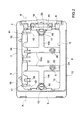
- the control plate assembly 1 may be assembled both with the buttons 5 arranged side-by-side along one side, for example the upper horizontal side 8, of counterplate 2 and therefore with horizontal rotation axes R, as diagrammatically shown in figure 5 ; and with the buttons 5 arranged facing and opposite each other along opposite sides, for example the vertical sides 9, of counterplate 2, with vertical rotation axes R, as diagrammatically shown in figure 6 .
- a plurality of different cover plates 3 may be implemented, having different aesthetic appearances, in particular different shape of window 29; and a plurality of control buttons 5 associated with each different plate 3, designed to be coordinated with plate 3 and in particular with the driving portion 33 being insertable into the window of plate 3.
- buttons 5 and 6 shows, in the two configurations with buttons 5 placed side-by-side and buttons 5 placed opposite to each other, the areas available for designing the buttons 5 with respect to plate 3 (also drawn with dotted line) and to counterplate 2; however, the buttons 5 are hinged to the counterplate 2 via the respective supports 30 and contact the respective actuating members 6 in respective actuation areas 50 (about the heads 26 of the actuating members 6).
- the control plate assembly 1 may therefore be made in different shapes.
- control plate assembly 1 In order to change the aesthetic appearance of the control plate assembly 1, it is sufficient to use a different cover plate 3 and one or two buttons 5 coordinated with plate 3, while the counterplate 2 and the supports 30 remain unvaried.
- control plate assemblies 1 having different aesthetic aspect
- the invention also provides a system for assembling control plate assemblies having different appearance;
- the system comprises the mounting counterplate 2 (i.e. only one type of counterplate); a plurality of cover plates 3, different from one another, interchangeable on counterplate 2 and mountable on counterplate 2 by means of the releasable connecting system 4; one or two buttons 5, coordinated with each plate 3 and different from the buttons 5 associated with other plates 3; one or two supports 30 of the same type (equal).
- buttons 5 associated with the different plates 3 are selectively attachable to the same counterplate 2 via a support 30, which is suitable for all the buttons 5 as it is rotatably (i.e. pivotally) couplable to each button 5 and attachable to counterplate 2.
- control plate assembly 1 is thus assembled by the method which comprises the steps of:
Landscapes
- Engineering & Computer Science (AREA)
- Mechanical Engineering (AREA)
- Aviation & Aerospace Engineering (AREA)
- Health & Medical Sciences (AREA)
- Life Sciences & Earth Sciences (AREA)
- Hydrology & Water Resources (AREA)
- Public Health (AREA)
- Water Supply & Treatment (AREA)
- Sanitary Device For Flush Toilet (AREA)
- Vehicle Step Arrangements And Article Storage (AREA)
- Casings For Electric Apparatus (AREA)
Applications Claiming Priority (1)
| Application Number | Priority Date | Filing Date | Title |
|---|---|---|---|
| ITMI20140290 | 2014-02-26 |
Publications (2)
| Publication Number | Publication Date |
|---|---|
| EP2913450A1 true EP2913450A1 (de) | 2015-09-02 |
| EP2913450B1 EP2913450B1 (de) | 2017-02-01 |
Family
ID=50630902
Family Applications (1)
| Application Number | Title | Priority Date | Filing Date |
|---|---|---|---|
| EP15398001.6A Not-in-force EP2913450B1 (de) | 2014-02-26 | 2015-02-26 | Steuerungsplattenanordnung eines spültanks und anordnungssystem und verfahren dafür |
Country Status (2)
| Country | Link |
|---|---|
| EP (1) | EP2913450B1 (de) |
| RU (1) | RU2671097C2 (de) |
Cited By (5)
| Publication number | Priority date | Publication date | Assignee | Title |
|---|---|---|---|---|
| WO2018203858A3 (en) * | 2016-12-24 | 2019-01-24 | Eczacibaşi Yapi Gereçleri̇ Sanayi̇ Ve Ti̇caret Anoni̇m Şi̇rketi̇ | HIDDEN TANK CONTROL PANEL |
| IT201900003431A1 (it) | 2019-03-08 | 2020-09-08 | Oli Sist Sanitarios S A | Gruppo placca di comando per una cassetta di risciacquo, e sistema e metodo per allestirla |
| EP4279675A1 (de) | 2022-05-17 | 2023-11-22 | Geberit International AG | Betätigungseinheit |
| EP4279672A1 (de) | 2022-05-17 | 2023-11-22 | Geberit International AG | Betätigungseinheit |
| EP4353918A1 (de) * | 2022-10-13 | 2024-04-17 | Geberit International AG | Betätigungsvorrichtung |
Families Citing this family (1)
| Publication number | Priority date | Publication date | Assignee | Title |
|---|---|---|---|---|
| EP4729705A1 (de) * | 2024-10-18 | 2026-04-22 | Geberit International AG | Betätigungseinheit |
Citations (3)
| Publication number | Priority date | Publication date | Assignee | Title |
|---|---|---|---|---|
| DE202006013859U1 (de) * | 2006-09-07 | 2006-11-02 | Mepa-Pauli Und Menden Gmbh | Steuerungsanordnung für einen Spülwasserkasten |
| DE202006012664U1 (de) * | 2006-08-17 | 2007-12-27 | Viega Gmbh & Co. Kg | Betätigungsvorrichtung für einen Urinal-Unterputzspüler oder WC-Unterputzspülkasten |
| EP2476808A1 (de) * | 2011-01-14 | 2012-07-18 | Geberit International AG | Betätigungsvorrichtung für einen Spülkasten |
Family Cites Families (1)
| Publication number | Priority date | Publication date | Assignee | Title |
|---|---|---|---|---|
| DE202007002924U1 (de) * | 2007-02-26 | 2008-07-10 | Viega Gmbh & Co. Kg | Vorrichtung zur elektrischen Auslösung einer WC-Spülung |
-
2015
- 2015-02-26 EP EP15398001.6A patent/EP2913450B1/de not_active Not-in-force
- 2015-02-26 RU RU2015106792A patent/RU2671097C2/ru not_active IP Right Cessation
Patent Citations (3)
| Publication number | Priority date | Publication date | Assignee | Title |
|---|---|---|---|---|
| DE202006012664U1 (de) * | 2006-08-17 | 2007-12-27 | Viega Gmbh & Co. Kg | Betätigungsvorrichtung für einen Urinal-Unterputzspüler oder WC-Unterputzspülkasten |
| DE202006013859U1 (de) * | 2006-09-07 | 2006-11-02 | Mepa-Pauli Und Menden Gmbh | Steuerungsanordnung für einen Spülwasserkasten |
| EP2476808A1 (de) * | 2011-01-14 | 2012-07-18 | Geberit International AG | Betätigungsvorrichtung für einen Spülkasten |
Cited By (6)
| Publication number | Priority date | Publication date | Assignee | Title |
|---|---|---|---|---|
| WO2018203858A3 (en) * | 2016-12-24 | 2019-01-24 | Eczacibaşi Yapi Gereçleri̇ Sanayi̇ Ve Ti̇caret Anoni̇m Şi̇rketi̇ | HIDDEN TANK CONTROL PANEL |
| IT201900003431A1 (it) | 2019-03-08 | 2020-09-08 | Oli Sist Sanitarios S A | Gruppo placca di comando per una cassetta di risciacquo, e sistema e metodo per allestirla |
| EP3705649A1 (de) | 2019-03-08 | 2020-09-09 | Oli - Sistemas Sanitarios, S.A. | Steuerungsplattenanordnung mit einen öffnungsmechanismus für einen spültank |
| EP4279675A1 (de) | 2022-05-17 | 2023-11-22 | Geberit International AG | Betätigungseinheit |
| EP4279672A1 (de) | 2022-05-17 | 2023-11-22 | Geberit International AG | Betätigungseinheit |
| EP4353918A1 (de) * | 2022-10-13 | 2024-04-17 | Geberit International AG | Betätigungsvorrichtung |
Also Published As
| Publication number | Publication date |
|---|---|
| RU2015106792A3 (de) | 2018-09-04 |
| EP2913450B1 (de) | 2017-02-01 |
| RU2015106792A (ru) | 2016-09-20 |
| RU2671097C2 (ru) | 2018-10-29 |
Similar Documents
| Publication | Publication Date | Title |
|---|---|---|
| EP2913450B1 (de) | Steuerungsplattenanordnung eines spültanks und anordnungssystem und verfahren dafür | |
| EP3705649B1 (de) | Steuerungsplattenanordnung mit einen öffnungsmechanismus für einen spültank | |
| ES2829330T3 (es) | Bisagra para una puerta o una ventana | |
| JP2016521370A5 (de) | ||
| ES2564631T3 (es) | Dispositivo de accionamiento para un fluxor empotrado de urinario o para una cisterna empotrada de inodoro | |
| JP6691436B2 (ja) | 秤の風防装置 | |
| EP2617906A1 (de) | Steuerungsplattenanordnung mit einen Öffnungsmechanismus für einen Spültank | |
| PT1898009E (pt) | Dispositivo de acionamento para um objeto sanitário, sobretudo para um autoclismo de wc | |
| EP2617905B1 (de) | Steuerungsplattenanordnung eines Spültanks | |
| EP2360308B1 (de) | Kontrollpanel für ein Haushaltsgerät | |
| JP2011252269A (ja) | 錠装置及び建具 | |
| KR101600273B1 (ko) | 미닫이 문짝의 거치용 브래킷 | |
| KR101030137B1 (ko) | 무늬판 교체 및 고정용 탈착장치가 구성된 문 | |
| JP5118955B2 (ja) | 建具や家具の取付け台座 | |
| EP2775050B1 (de) | Steuerungsplattenanordnung eines Spültanks | |
| EP4043653A1 (de) | Steuerungsplattenanordnung für einen spültank | |
| JP6570318B2 (ja) | 基板ユニットのロック構造 | |
| RU2663598C2 (ru) | Узел управляющей пластины смывного бачка | |
| JP7748699B2 (ja) | 戸先錠 | |
| KR20160029056A (ko) | 미닫이 문짝의 거치용 브래킷 | |
| JP7454356B2 (ja) | トイレ装置用リモコン装置 | |
| EP1806815A1 (de) | Ein Schaltschrankgehäuse | |
| KR200326569Y1 (ko) | 슬랫회전조절기어 | |
| KR200343365Y1 (ko) | 범용 캐비넷 래치 | |
| JP6471404B2 (ja) | トイレ用手すり |
Legal Events
| Date | Code | Title | Description |
|---|---|---|---|
| PUAI | Public reference made under article 153(3) epc to a published international application that has entered the european phase |
Free format text: ORIGINAL CODE: 0009012 |
|
| AK | Designated contracting states |
Kind code of ref document: A1 Designated state(s): AL AT BE BG CH CY CZ DE DK EE ES FI FR GB GR HR HU IE IS IT LI LT LU LV MC MK MT NL NO PL PT RO RS SE SI SK SM TR |
|
| AX | Request for extension of the european patent |
Extension state: BA ME |
|
| 17P | Request for examination filed |
Effective date: 20160229 |
|
| RBV | Designated contracting states (corrected) |
Designated state(s): AL AT BE BG CH CY CZ DE DK EE ES FI FR GB GR HR HU IE IS IT LI LT LU LV MC MK MT NL NO PL PT RO RS SE SI SK SM TR |
|
| GRAP | Despatch of communication of intention to grant a patent |
Free format text: ORIGINAL CODE: EPIDOSNIGR1 |
|
| INTG | Intention to grant announced |
Effective date: 20160915 |
|
| GRAS | Grant fee paid |
Free format text: ORIGINAL CODE: EPIDOSNIGR3 |
|
| GRAA | (expected) grant |
Free format text: ORIGINAL CODE: 0009210 |
|
| AK | Designated contracting states |
Kind code of ref document: B1 Designated state(s): AL AT BE BG CH CY CZ DE DK EE ES FI FR GB GR HR HU IE IS IT LI LT LU LV MC MK MT NL NO PL PT RO RS SE SI SK SM TR |
|
| REG | Reference to a national code |
Ref country code: GB Ref legal event code: FG4D |
|
| REG | Reference to a national code |
Ref country code: CH Ref legal event code: EP Ref country code: AT Ref legal event code: REF Ref document number: 865731 Country of ref document: AT Kind code of ref document: T Effective date: 20170215 |
|
| REG | Reference to a national code |
Ref country code: IE Ref legal event code: FG4D |
|
| REG | Reference to a national code |
Ref country code: DE Ref legal event code: R096 Ref document number: 602015001440 Country of ref document: DE |
|
| REG | Reference to a national code |
Ref country code: NL Ref legal event code: MP Effective date: 20170201 |
|
| REG | Reference to a national code |
Ref country code: LT Ref legal event code: MG4D |
|
| REG | Reference to a national code |
Ref country code: AT Ref legal event code: MK05 Ref document number: 865731 Country of ref document: AT Kind code of ref document: T Effective date: 20170201 |
|
| PG25 | Lapsed in a contracting state [announced via postgrant information from national office to epo] |
Ref country code: IS Free format text: LAPSE BECAUSE OF FAILURE TO SUBMIT A TRANSLATION OF THE DESCRIPTION OR TO PAY THE FEE WITHIN THE PRESCRIBED TIME-LIMIT Effective date: 20170601 Ref country code: NO Free format text: LAPSE BECAUSE OF FAILURE TO SUBMIT A TRANSLATION OF THE DESCRIPTION OR TO PAY THE FEE WITHIN THE PRESCRIBED TIME-LIMIT Effective date: 20170501 Ref country code: GR Free format text: LAPSE BECAUSE OF FAILURE TO SUBMIT A TRANSLATION OF THE DESCRIPTION OR TO PAY THE FEE WITHIN THE PRESCRIBED TIME-LIMIT Effective date: 20170502 Ref country code: LT Free format text: LAPSE BECAUSE OF FAILURE TO SUBMIT A TRANSLATION OF THE DESCRIPTION OR TO PAY THE FEE WITHIN THE PRESCRIBED TIME-LIMIT Effective date: 20170201 Ref country code: FI Free format text: LAPSE BECAUSE OF FAILURE TO SUBMIT A TRANSLATION OF THE DESCRIPTION OR TO PAY THE FEE WITHIN THE PRESCRIBED TIME-LIMIT Effective date: 20170201 Ref country code: HR Free format text: LAPSE BECAUSE OF FAILURE TO SUBMIT A TRANSLATION OF THE DESCRIPTION OR TO PAY THE FEE WITHIN THE PRESCRIBED TIME-LIMIT Effective date: 20170201 |
|
| PG25 | Lapsed in a contracting state [announced via postgrant information from national office to epo] |
Ref country code: ES Free format text: LAPSE BECAUSE OF FAILURE TO SUBMIT A TRANSLATION OF THE DESCRIPTION OR TO PAY THE FEE WITHIN THE PRESCRIBED TIME-LIMIT Effective date: 20170201 Ref country code: BG Free format text: LAPSE BECAUSE OF FAILURE TO SUBMIT A TRANSLATION OF THE DESCRIPTION OR TO PAY THE FEE WITHIN THE PRESCRIBED TIME-LIMIT Effective date: 20170501 Ref country code: PT Free format text: LAPSE BECAUSE OF FAILURE TO SUBMIT A TRANSLATION OF THE DESCRIPTION OR TO PAY THE FEE WITHIN THE PRESCRIBED TIME-LIMIT Effective date: 20170601 Ref country code: RS Free format text: LAPSE BECAUSE OF FAILURE TO SUBMIT A TRANSLATION OF THE DESCRIPTION OR TO PAY THE FEE WITHIN THE PRESCRIBED TIME-LIMIT Effective date: 20170201 Ref country code: AT Free format text: LAPSE BECAUSE OF FAILURE TO SUBMIT A TRANSLATION OF THE DESCRIPTION OR TO PAY THE FEE WITHIN THE PRESCRIBED TIME-LIMIT Effective date: 20170201 Ref country code: NL Free format text: LAPSE BECAUSE OF FAILURE TO SUBMIT A TRANSLATION OF THE DESCRIPTION OR TO PAY THE FEE WITHIN THE PRESCRIBED TIME-LIMIT Effective date: 20170201 Ref country code: PL Free format text: LAPSE BECAUSE OF FAILURE TO SUBMIT A TRANSLATION OF THE DESCRIPTION OR TO PAY THE FEE WITHIN THE PRESCRIBED TIME-LIMIT Effective date: 20170201 Ref country code: LV Free format text: LAPSE BECAUSE OF FAILURE TO SUBMIT A TRANSLATION OF THE DESCRIPTION OR TO PAY THE FEE WITHIN THE PRESCRIBED TIME-LIMIT Effective date: 20170201 Ref country code: SE Free format text: LAPSE BECAUSE OF FAILURE TO SUBMIT A TRANSLATION OF THE DESCRIPTION OR TO PAY THE FEE WITHIN THE PRESCRIBED TIME-LIMIT Effective date: 20170201 |
|
| PG25 | Lapsed in a contracting state [announced via postgrant information from national office to epo] |
Ref country code: RO Free format text: LAPSE BECAUSE OF FAILURE TO SUBMIT A TRANSLATION OF THE DESCRIPTION OR TO PAY THE FEE WITHIN THE PRESCRIBED TIME-LIMIT Effective date: 20170201 Ref country code: SK Free format text: LAPSE BECAUSE OF FAILURE TO SUBMIT A TRANSLATION OF THE DESCRIPTION OR TO PAY THE FEE WITHIN THE PRESCRIBED TIME-LIMIT Effective date: 20170201 Ref country code: CZ Free format text: LAPSE BECAUSE OF FAILURE TO SUBMIT A TRANSLATION OF THE DESCRIPTION OR TO PAY THE FEE WITHIN THE PRESCRIBED TIME-LIMIT Effective date: 20170201 Ref country code: EE Free format text: LAPSE BECAUSE OF FAILURE TO SUBMIT A TRANSLATION OF THE DESCRIPTION OR TO PAY THE FEE WITHIN THE PRESCRIBED TIME-LIMIT Effective date: 20170201 |
|
| REG | Reference to a national code |
Ref country code: DE Ref legal event code: R097 Ref document number: 602015001440 Country of ref document: DE |
|
| REG | Reference to a national code |
Ref country code: IE Ref legal event code: MM4A |
|
| PG25 | Lapsed in a contracting state [announced via postgrant information from national office to epo] |
Ref country code: MC Free format text: LAPSE BECAUSE OF FAILURE TO SUBMIT A TRANSLATION OF THE DESCRIPTION OR TO PAY THE FEE WITHIN THE PRESCRIBED TIME-LIMIT Effective date: 20170201 Ref country code: DK Free format text: LAPSE BECAUSE OF FAILURE TO SUBMIT A TRANSLATION OF THE DESCRIPTION OR TO PAY THE FEE WITHIN THE PRESCRIBED TIME-LIMIT Effective date: 20170201 Ref country code: SM Free format text: LAPSE BECAUSE OF FAILURE TO SUBMIT A TRANSLATION OF THE DESCRIPTION OR TO PAY THE FEE WITHIN THE PRESCRIBED TIME-LIMIT Effective date: 20170201 |
|
| PLBE | No opposition filed within time limit |
Free format text: ORIGINAL CODE: 0009261 |
|
| STAA | Information on the status of an ep patent application or granted ep patent |
Free format text: STATUS: NO OPPOSITION FILED WITHIN TIME LIMIT |
|
| PG25 | Lapsed in a contracting state [announced via postgrant information from national office to epo] |
Ref country code: LU Free format text: LAPSE BECAUSE OF NON-PAYMENT OF DUE FEES Effective date: 20170226 |
|
| 26N | No opposition filed |
Effective date: 20171103 |
|
| REG | Reference to a national code |
Ref country code: FR Ref legal event code: ST Effective date: 20171220 |
|
| PG25 | Lapsed in a contracting state [announced via postgrant information from national office to epo] |
Ref country code: FR Free format text: LAPSE BECAUSE OF NON-PAYMENT OF DUE FEES Effective date: 20170403 |
|
| REG | Reference to a national code |
Ref country code: BE Ref legal event code: MM Effective date: 20170228 |
|
| PG25 | Lapsed in a contracting state [announced via postgrant information from national office to epo] |
Ref country code: IE Free format text: LAPSE BECAUSE OF NON-PAYMENT OF DUE FEES Effective date: 20170226 Ref country code: SI Free format text: LAPSE BECAUSE OF FAILURE TO SUBMIT A TRANSLATION OF THE DESCRIPTION OR TO PAY THE FEE WITHIN THE PRESCRIBED TIME-LIMIT Effective date: 20170201 |
|
| PG25 | Lapsed in a contracting state [announced via postgrant information from national office to epo] |
Ref country code: BE Free format text: LAPSE BECAUSE OF NON-PAYMENT OF DUE FEES Effective date: 20170228 |
|
| PGFP | Annual fee paid to national office [announced via postgrant information from national office to epo] |
Ref country code: IT Payment date: 20180228 Year of fee payment: 4 |
|
| PGFP | Annual fee paid to national office [announced via postgrant information from national office to epo] |
Ref country code: DE Payment date: 20180430 Year of fee payment: 4 |
|
| REG | Reference to a national code |
Ref country code: CH Ref legal event code: PL |
|
| PG25 | Lapsed in a contracting state [announced via postgrant information from national office to epo] |
Ref country code: MT Free format text: LAPSE BECAUSE OF NON-PAYMENT OF DUE FEES Effective date: 20170226 |
|
| PG25 | Lapsed in a contracting state [announced via postgrant information from national office to epo] |
Ref country code: LI Free format text: LAPSE BECAUSE OF NON-PAYMENT OF DUE FEES Effective date: 20180228 Ref country code: CH Free format text: LAPSE BECAUSE OF NON-PAYMENT OF DUE FEES Effective date: 20180228 |
|
| PG25 | Lapsed in a contracting state [announced via postgrant information from national office to epo] |
Ref country code: HU Free format text: LAPSE BECAUSE OF FAILURE TO SUBMIT A TRANSLATION OF THE DESCRIPTION OR TO PAY THE FEE WITHIN THE PRESCRIBED TIME-LIMIT; INVALID AB INITIO Effective date: 20150226 |
|
| REG | Reference to a national code |
Ref country code: DE Ref legal event code: R119 Ref document number: 602015001440 Country of ref document: DE |
|
| GBPC | Gb: european patent ceased through non-payment of renewal fee |
Effective date: 20190226 |
|
| PG25 | Lapsed in a contracting state [announced via postgrant information from national office to epo] |
Ref country code: CY Free format text: LAPSE BECAUSE OF FAILURE TO SUBMIT A TRANSLATION OF THE DESCRIPTION OR TO PAY THE FEE WITHIN THE PRESCRIBED TIME-LIMIT Effective date: 20170201 |
|
| PG25 | Lapsed in a contracting state [announced via postgrant information from national office to epo] |
Ref country code: MK Free format text: LAPSE BECAUSE OF FAILURE TO SUBMIT A TRANSLATION OF THE DESCRIPTION OR TO PAY THE FEE WITHIN THE PRESCRIBED TIME-LIMIT Effective date: 20170201 |
|
| PG25 | Lapsed in a contracting state [announced via postgrant information from national office to epo] |
Ref country code: GB Free format text: LAPSE BECAUSE OF NON-PAYMENT OF DUE FEES Effective date: 20190226 Ref country code: DE Free format text: LAPSE BECAUSE OF NON-PAYMENT OF DUE FEES Effective date: 20190903 |
|
| PG25 | Lapsed in a contracting state [announced via postgrant information from national office to epo] |
Ref country code: IT Free format text: LAPSE BECAUSE OF NON-PAYMENT OF DUE FEES Effective date: 20190226 |
|
| PG25 | Lapsed in a contracting state [announced via postgrant information from national office to epo] |
Ref country code: TR Free format text: LAPSE BECAUSE OF FAILURE TO SUBMIT A TRANSLATION OF THE DESCRIPTION OR TO PAY THE FEE WITHIN THE PRESCRIBED TIME-LIMIT Effective date: 20170201 |
|
| PG25 | Lapsed in a contracting state [announced via postgrant information from national office to epo] |
Ref country code: AL Free format text: LAPSE BECAUSE OF FAILURE TO SUBMIT A TRANSLATION OF THE DESCRIPTION OR TO PAY THE FEE WITHIN THE PRESCRIBED TIME-LIMIT Effective date: 20170201 |