EP2913495B1 - Procédé de fabrication d'un dispositif de post-traitement de gaz d'échappement et dispositif de post-traitement de gaz d'échappement correspondant - Google Patents
Procédé de fabrication d'un dispositif de post-traitement de gaz d'échappement et dispositif de post-traitement de gaz d'échappement correspondant Download PDFInfo
- Publication number
- EP2913495B1 EP2913495B1 EP14197087.1A EP14197087A EP2913495B1 EP 2913495 B1 EP2913495 B1 EP 2913495B1 EP 14197087 A EP14197087 A EP 14197087A EP 2913495 B1 EP2913495 B1 EP 2913495B1
- Authority
- EP
- European Patent Office
- Prior art keywords
- housing
- axial
- substrate body
- support
- axially
- Prior art date
- Legal status (The legal status is an assumption and is not a legal conclusion. Google has not performed a legal analysis and makes no representation as to the accuracy of the status listed.)
- Active
Links
Images
Classifications
-
- F—MECHANICAL ENGINEERING; LIGHTING; HEATING; WEAPONS; BLASTING
- F01—MACHINES OR ENGINES IN GENERAL; ENGINE PLANTS IN GENERAL; STEAM ENGINES
- F01N—GAS-FLOW SILENCERS OR EXHAUST APPARATUS FOR MACHINES OR ENGINES IN GENERAL; GAS-FLOW SILENCERS OR EXHAUST APPARATUS FOR INTERNAL-COMBUSTION ENGINES
- F01N3/00—Exhaust or silencing apparatus having means for purifying, rendering innocuous, or otherwise treating exhaust
- F01N3/08—Exhaust or silencing apparatus having means for purifying, rendering innocuous, or otherwise treating exhaust for rendering innocuous
- F01N3/10—Exhaust or silencing apparatus having means for purifying, rendering innocuous, or otherwise treating exhaust for rendering innocuous by thermal or catalytic conversion of noxious components of exhaust
- F01N3/18—Exhaust or silencing apparatus having means for purifying, rendering innocuous, or otherwise treating exhaust for rendering innocuous by thermal or catalytic conversion of noxious components of exhaust characterised by methods of operation; Control
- F01N3/20—Exhaust or silencing apparatus having means for purifying, rendering innocuous, or otherwise treating exhaust for rendering innocuous by thermal or catalytic conversion of noxious components of exhaust characterised by methods of operation; Control specially adapted for catalytic conversion
-
- F—MECHANICAL ENGINEERING; LIGHTING; HEATING; WEAPONS; BLASTING
- F01—MACHINES OR ENGINES IN GENERAL; ENGINE PLANTS IN GENERAL; STEAM ENGINES
- F01N—GAS-FLOW SILENCERS OR EXHAUST APPARATUS FOR MACHINES OR ENGINES IN GENERAL; GAS-FLOW SILENCERS OR EXHAUST APPARATUS FOR INTERNAL-COMBUSTION ENGINES
- F01N3/00—Exhaust or silencing apparatus having means for purifying, rendering innocuous, or otherwise treating exhaust
- F01N3/08—Exhaust or silencing apparatus having means for purifying, rendering innocuous, or otherwise treating exhaust for rendering innocuous
- F01N3/10—Exhaust or silencing apparatus having means for purifying, rendering innocuous, or otherwise treating exhaust for rendering innocuous by thermal or catalytic conversion of noxious components of exhaust
- F01N3/24—Exhaust or silencing apparatus having means for purifying, rendering innocuous, or otherwise treating exhaust for rendering innocuous by thermal or catalytic conversion of noxious components of exhaust characterised by constructional aspects of converting apparatus
- F01N3/28—Construction of catalytic reactors
- F01N3/2803—Construction of catalytic reactors characterised by structure, by material or by manufacturing of catalyst support
- F01N3/2825—Ceramics
- F01N3/2828—Ceramic multi-channel monoliths, e.g. honeycombs
-
- B—PERFORMING OPERATIONS; TRANSPORTING
- B23—MACHINE TOOLS; METAL-WORKING NOT OTHERWISE PROVIDED FOR
- B23K—SOLDERING OR UNSOLDERING; WELDING; CLADDING OR PLATING BY SOLDERING OR WELDING; CUTTING BY APPLYING HEAT LOCALLY, e.g. FLAME CUTTING; WORKING BY LASER BEAM
- B23K31/00—Processes relevant to this subclass, specially adapted for particular articles or purposes, but not covered by any single one of main groups B23K1/00 - B23K28/00
- B23K31/02—Processes relevant to this subclass, specially adapted for particular articles or purposes, but not covered by any single one of main groups B23K1/00 - B23K28/00 relating to soldering or welding
-
- F—MECHANICAL ENGINEERING; LIGHTING; HEATING; WEAPONS; BLASTING
- F01—MACHINES OR ENGINES IN GENERAL; ENGINE PLANTS IN GENERAL; STEAM ENGINES
- F01N—GAS-FLOW SILENCERS OR EXHAUST APPARATUS FOR MACHINES OR ENGINES IN GENERAL; GAS-FLOW SILENCERS OR EXHAUST APPARATUS FOR INTERNAL-COMBUSTION ENGINES
- F01N13/00—Exhaust or silencing apparatus characterised by constructional features
- F01N13/009—Exhaust or silencing apparatus characterised by constructional features having two or more separate purifying devices arranged in series
- F01N13/0097—Exhaust or silencing apparatus characterised by constructional features having two or more separate purifying devices arranged in series the purifying devices are arranged in a single housing
-
- F—MECHANICAL ENGINEERING; LIGHTING; HEATING; WEAPONS; BLASTING
- F01—MACHINES OR ENGINES IN GENERAL; ENGINE PLANTS IN GENERAL; STEAM ENGINES
- F01N—GAS-FLOW SILENCERS OR EXHAUST APPARATUS FOR MACHINES OR ENGINES IN GENERAL; GAS-FLOW SILENCERS OR EXHAUST APPARATUS FOR INTERNAL-COMBUSTION ENGINES
- F01N3/00—Exhaust or silencing apparatus having means for purifying, rendering innocuous, or otherwise treating exhaust
- F01N3/08—Exhaust or silencing apparatus having means for purifying, rendering innocuous, or otherwise treating exhaust for rendering innocuous
- F01N3/10—Exhaust or silencing apparatus having means for purifying, rendering innocuous, or otherwise treating exhaust for rendering innocuous by thermal or catalytic conversion of noxious components of exhaust
- F01N3/18—Exhaust or silencing apparatus having means for purifying, rendering innocuous, or otherwise treating exhaust for rendering innocuous by thermal or catalytic conversion of noxious components of exhaust characterised by methods of operation; Control
-
- F—MECHANICAL ENGINEERING; LIGHTING; HEATING; WEAPONS; BLASTING
- F01—MACHINES OR ENGINES IN GENERAL; ENGINE PLANTS IN GENERAL; STEAM ENGINES
- F01N—GAS-FLOW SILENCERS OR EXHAUST APPARATUS FOR MACHINES OR ENGINES IN GENERAL; GAS-FLOW SILENCERS OR EXHAUST APPARATUS FOR INTERNAL-COMBUSTION ENGINES
- F01N3/00—Exhaust or silencing apparatus having means for purifying, rendering innocuous, or otherwise treating exhaust
- F01N3/08—Exhaust or silencing apparatus having means for purifying, rendering innocuous, or otherwise treating exhaust for rendering innocuous
- F01N3/10—Exhaust or silencing apparatus having means for purifying, rendering innocuous, or otherwise treating exhaust for rendering innocuous by thermal or catalytic conversion of noxious components of exhaust
- F01N3/24—Exhaust or silencing apparatus having means for purifying, rendering innocuous, or otherwise treating exhaust for rendering innocuous by thermal or catalytic conversion of noxious components of exhaust characterised by constructional aspects of converting apparatus
- F01N3/28—Construction of catalytic reactors
- F01N3/2839—Arrangements for mounting catalyst support in housing, e.g. with means for compensating thermal expansion or vibration
- F01N3/2853—Arrangements for mounting catalyst support in housing, e.g. with means for compensating thermal expansion or vibration using mats or gaskets between catalyst body and housing
-
- F—MECHANICAL ENGINEERING; LIGHTING; HEATING; WEAPONS; BLASTING
- F01—MACHINES OR ENGINES IN GENERAL; ENGINE PLANTS IN GENERAL; STEAM ENGINES
- F01N—GAS-FLOW SILENCERS OR EXHAUST APPARATUS FOR MACHINES OR ENGINES IN GENERAL; GAS-FLOW SILENCERS OR EXHAUST APPARATUS FOR INTERNAL-COMBUSTION ENGINES
- F01N3/00—Exhaust or silencing apparatus having means for purifying, rendering innocuous, or otherwise treating exhaust
- F01N3/08—Exhaust or silencing apparatus having means for purifying, rendering innocuous, or otherwise treating exhaust for rendering innocuous
- F01N3/10—Exhaust or silencing apparatus having means for purifying, rendering innocuous, or otherwise treating exhaust for rendering innocuous by thermal or catalytic conversion of noxious components of exhaust
- F01N3/24—Exhaust or silencing apparatus having means for purifying, rendering innocuous, or otherwise treating exhaust for rendering innocuous by thermal or catalytic conversion of noxious components of exhaust characterised by constructional aspects of converting apparatus
- F01N3/28—Construction of catalytic reactors
- F01N3/2839—Arrangements for mounting catalyst support in housing, e.g. with means for compensating thermal expansion or vibration
- F01N3/2853—Arrangements for mounting catalyst support in housing, e.g. with means for compensating thermal expansion or vibration using mats or gaskets between catalyst body and housing
- F01N3/2867—Arrangements for mounting catalyst support in housing, e.g. with means for compensating thermal expansion or vibration using mats or gaskets between catalyst body and housing the mats or gaskets being placed at the front or end face of catalyst body
-
- F—MECHANICAL ENGINEERING; LIGHTING; HEATING; WEAPONS; BLASTING
- F01—MACHINES OR ENGINES IN GENERAL; ENGINE PLANTS IN GENERAL; STEAM ENGINES
- F01N—GAS-FLOW SILENCERS OR EXHAUST APPARATUS FOR MACHINES OR ENGINES IN GENERAL; GAS-FLOW SILENCERS OR EXHAUST APPARATUS FOR INTERNAL-COMBUSTION ENGINES
- F01N2450/00—Methods or apparatus for fitting, inserting or repairing different elements
- F01N2450/02—Fitting monolithic blocks into the housing
Definitions
- the present invention relates to a method for producing an exhaust gas aftertreatment device.
- the invention also relates to an exhaust aftertreatment device produced by this method.
- the substrate bodies can be catalytically actively coated depending on the cleaning application, for example in order to form an oxidation catalyst or a DeNox catalyst or a three-way catalyst or a hydrolysis catalyst or an ammonia-barrier catalyst.
- the substrate body are usually made of one piece of material uniform, ie monolithic, so that they each form a monolith.
- two or more ceramic substrate body can be flowed through one behind the other.
- it can be possible to increase the efficiency of arranging two or more substrate bodies one behind the other.
- two or more substrate bodies may be arranged one behind the other, which differ, for example, from one another by different pore sizes. Also substrate body with different cleaning jobs, so in particular with different catalytic coatings, be arranged in a common housing one behind the other.
- such an exhaust gas aftertreatment device may have a tubular housing in which either exactly one ceramic substrate body for exhaust gas aftertreatment is arranged or at least two ceramic substrate bodies are arranged behind one another for exhaust gas aftertreatment.
- a storage of such ceramic substrate body in a metallic housing by means of bearing mats.
- the bearing mats are radially compressed.
- the insertion of the substrate body with bearing mat in the housing is commonly referred to as "Canning”.
- an axial Canning in which the respective substrate body is axially introduced with the bearing mat in the tubular housing.
- the upstream substrate body in a housing containing such an axial support, the upstream substrate body must be inserted into the housing from an inlet side of the housing, while the downstream substrate body must be inserted into the housing through an outlet side of the housing, and then axially between the axial support is arranged the two substrate bodies.
- the housing Depending on the canning process, the housing must be turned in a suitable canning facility.
- an exhaust aftertreatment device which contains only a single substrate body, is also an axial support for protection against a collision of Substrate body with the housing desirable, showing similar problems in the production.
- the US 4,581,206 A1 shows an exhaust aftertreatment device with a housing and two Substratkörpem arranged therein, which are axially inserted into the housing and axially held by means of axial elements in the housing.
- an axially displaceable middle plate is arranged between the substrate bodies.
- an exhaust aftertreatment device is shown with a housing in which a substrate body is arranged and axially spaced from the housing.
- the present invention is concerned with the problem of providing for such an exhaust aftertreatment device or for an associated manufacturing method an improved or at least another embodiment, which is characterized in particular by a reduced risk of damage to the respective substrate body and optionally by a simplified production.
- the invention is based on the general idea of performing canning by first inserting a substrate body with a bearing mat into the housing, then inserting an axial support into the housing and positioning it in a predetermined manner for axial support of the first substrate body in the housing Finally, the axial support is fixed in the desired position and desired axial bias between the substrate body and Axialabstützung on the housing.
- the axial positioning of the substrate body is improved in a predetermined relative position in the housing and reduces the risk of displacement of the substrate body during operation of the exhaust aftertreatment device. Since even such an axial displacement between the substrate body and housing brings with it the risk of damaging the substrate body, this prestressed positioning and fixing can reduce the risk of damage to the substrate body.
- At least two substrate body are provided, wherein after inserting a first substrate body with a first bearing mat and after inserting, positioning and fixing the Axialabstützung a second substrate body with second bearing mat is inserted into the housing, such that subsequently the AxialabstNeillung axially between the first Substrate body and the second substrate body is arranged.
- the mounting takes place in such a way that the respective substrate body is supported axially only on one side, namely exclusively on the outlet side or downstream on such axial securing, with the respectively predetermined axial prestressing.
- the respective Axialabstützung is preferably formed by means of a support ring and an annular support member held by the support ring.
- the Axialabstützung can be positioned in the housing so that it transmits a predetermined axial force on the previously inserted into the housing first substrate body via the support member.
- this can be measured at the onset of the AxialabstNeillung occurring during pressing of the AxialabstNeillung against the first substrate body axial force and adjusted to a predetermined value.
- Particularly advantageous is a development of the method in which the axial support is fixed in this axially biased positioning on the housing.
- the support ring can be welded to the housing.
- the set, predetermined axial force between the axial support and the first substrate body can virtually freeze.
- an axial prestressed mounting of the first substrate body is realized at the Axialabstützung, although the AxialabstNeillung only after the first substrate body in the Housing is used.
- An axially biased mounting is advantageous because it reduces the risk of axial displacement of the upstream substrate.
- the canning device required for this purpose thus comprises a positioning device with the aid of which the axial support can be introduced into the housing and can be supported with the predetermined axial force on the first substrate.
- the positioning device can be equipped with an axial force measuring device. Further, this positioning is expediently designed so that it can position the axial support also during the respective welding operation with the desired bias relative to the housing.
- the support ring can be pressed radially against the housing before welding and welded in this pressed state with the housing.
- the support ring is fixed in the radial direction quasi clearance and gap-free on the housing, whereby a particularly efficient and durable welded joint can be realized.
- the associated positioning device is then designed in particular for widening the support ring, so that it can press the support ring for the welding process radially against the housing.
- the support ring may have an interruption in the circumferential direction, so that it is elastically deformable with respect to its diameter for radial pressing against the housing.
- the simply interrupted in the circumferential direction support ring simplifies the radial pressing of the support ring to the housing.
- the support element may be designed to be closed or uninterrupted in the circumferential direction.
- the Support member has a certain axial elasticity for the axial support of the first substrate body. The axial elasticity can be accompanied by a sufficient elasticity in the circumferential direction, so that the support member of the expansion of the support ring can easily follow elastically.
- the support ring may have a retaining region holding the support element and a fixing region provided for welding to the housing.
- the fixing area is expediently axial over the holding area and the supporting element.
- lever arms which reduce a bending load of the respective welded connection arising during the axial force transmission arise within the axial support, so that the respective welded connection essentially only has to transmit shear forces, ie tensile forces running parallel to the longitudinal central axis of the housing. This gives the particular weld a particularly high durability.
- an axial edge of the first bearing mat facing the axial support can be offset axially relative to an axial end face of the first substrate body facing the axial support, so that said edge of the first bearing mat axially delimits the radial gap in which the aforementioned fixing area engages axially. Due to this axial offset between the first bearing mat and the first substrate body, the fixing region of the support ring can be introduced into the radial gap without damaging the bearing mat.
- the welding for fixing the axial support to the housing may be performed from an outside of the housing, radially through the housing. This simplifies the manufacture, since the AxialabstNeillung can be positioned using the aforementioned positioning on an inner side of the housing in a desired manner, while the fixation of the AxialabstNeillung on the outside by means of a corresponding welding device.
- the welding of the axial support on the housing can be carried out as a laser sweep welding.
- a spot welding process can also be used.
- laser sweep welding discrete, ie limited in their longitudinal direction welds are produced by laser welding technology.
- the longitudinal direction of the welds expediently extends in the circumferential direction of the housing. Accordingly, a plurality of welds distributed in the circumferential direction and arranged at a distance from one another are thus produced in order to fix the axial support to the housing.
- the housing may be unperforated in the region of the axial support and welded in the unperforated state with the support ring.
- the fixation of the support is simplified on the housing, since no openings in the housing must be arranged in advance, for example. To produce welds. The welding takes place through the housing or through the material of the housing.
- a support element a wire knit, which during the axial preloading of the axial Support is elastically deformed.
- a knitted fabric is characterized by a permanent elasticity even at high temperatures.
- the support ring may be provided with a U-profile, which has an outer leg and an inner leg for radial positioning of the support element and a base connecting the outer leg with the inner leg for axial positioning of the support element.
- a cross section of the support ring having the U-profile lies in a sectional plane containing the longitudinal central axis of the housing.
- the U-profile extends in the circumferential direction of the support ring. Due to the U-profile, the support element is securely positioned on the support ring.
- the outer leg projects axially beyond the inner leg and preferably also via the support element and is welded to the housing.
- the outer leg then forms the above-mentioned fixing region of the support ring.
- the welded connection is thus axially offset from the support element.
- an axial gap is formed, in which the support ring positions the support element.
- an axial dimension of the axial support within the axial gap may be smaller than an axial gap width of the axial gap. This ensures that the second substrate body from the Axialabstützung, in particular from the support ring of the Axialabstützung, axially spaced.
- the gap width can be at most 100%, preferably at most 50%, greater than the axial dimension of the axial support within the axial gap.
- the first substrate body, the axial support and the second substrate body can be inserted into the housing through the same axial opening of the housing. This simplifies the Canning process, since in particular a turning of the housing is eliminated.
- An exhaust aftertreatment device is characterized in that it is produced according to the method described above.
- such an exhaust aftertreatment device can be seen from the fact that even with unused exhaust aftertreatment device already exists an axial bias between the Axialabstützung and the respective substrate body.
- an exhaust aftertreatment device according to the invention which contains two or more substrate bodies, can be seen from the fact that only one of the two axial openings is suitable for introducing the substrate body and the axial support.
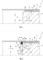
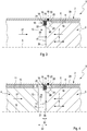
- Fig. 1 to 4 includes an exhaust aftertreatment device 1, which may be, for example, a catalyst or a particulate filter, a tubular housing 2, in which at least two ceramic substrate body, namely a first substrate body 3 and a second substrate body 4 are arranged.
- the two substrate body 3, 4 are arranged with respect to an axial direction 5, which is indicated in the figures by a double arrow, one behind the other.
- the axial direction 5 extends parallel to a longitudinal central axis 6 of the housing 2.
- the exhaust gas aftertreatment device 1 is intended for installation in an exhaust system of an internal combustion engine, preferably a motor vehicle, not shown here.
- an exhaust gas flow which flows through the housing 2 in a flow direction 7, occurs in the housing 2.
- the flow direction 7 is indicated in the figures by an arrow.
- the first substrate body 3 is arranged upstream of the second substrate body 4.
- the first substrate body 3 is mounted in the housing 2 by means of a first bearing mat 8 which, for this purpose, envelops the first substrate body 3 in the circumferential direction and is radially prestressed or pressed between the first substrate body 3 and the housing 2.
- first bearing mat 8 directly on an outer side 9 of the first substrate body 3 and directly to a Lying inside 10 of the housing 2.
- the second substrate body 4 is mounted with a second bearing mat 11 in the housing 2.
- the second bearing mat 11 surrounds the second substrate body 4 in the circumferential direction and is radially pressed or prestressed between the second substrate body 4 and the housing 2.
- the second bearing mat 11 can rest directly on an outer side 12 of the second substrate body 4 and directly on the inner side 10 of the housing 2.
- the exhaust gas aftertreatment device 1 also contains in the housing 2 an axial support 13, which has a support ring 14 and an annular support element 15, which is held by or on the support ring 14.
- the axial support 13 is fastened to the housing 2 by means of at least one welded connection 16.
- the first substrate body 3 is axially supported on the support element 15.
- more than two substrate bodies 3, 4 may also be arranged in the housing 2. It is also conceivable, in an embodiment which contains two or more substrate bodies 3, 4 in the housing 2, to provide two or more than two axial supports 13 in order to axially support the second substrate body 4, and in particular also each further substrate body, on the housing 2.
- each substrate body 3, 4 is assigned in each case only a single axial support 13, which is arranged at the respective substrate body 3, 4 at its outlet side or downstream side.
- Fig. 1 to 4 indicates the flow direction 7 to the left.
- the axial exit side of the respective substrate body 3, 4 is located on the left and is denoted by 26 in the substrate body 3 shown on the right.
- the respective substrate body 3, 4 is at its outlet-side end face 26 with a predetermined bias to the associated axial support 13, so even if no flow through the exhaust aftertreatment device 1 takes place.
- the support ring 14 has an interruption 17 in the circumferential direction, whereby the support ring 14 has a certain elasticity in the radial direction.
- the support element 15 is preferably configured in the circumferential direction without interruption.
- the support element 15 is formed by a wire mesh.
- the support ring 14 has in a cross-section containing the longitudinal central axis 6 a U-profile 18, which has a radially outer outer leg 19, a radially inner inner leg 20 and a base 21.
- the base 21 connects the outer leg 19 with the inner leg 20.
- Outer leg 19 and inner leg 20 form a radial positioning of the support member 15 on the support ring 14.
- the base 21 forms an axial positioning of the support member 15 on the support ring 14.
- the outer leg 19 axially over the inner leg 20 via.
- the outer leg 19 forms a fixing region 22 of the support ring 13, via which the support ring 13 is attached to the housing 2.
- the respective, aforementioned weld 16 is formed on or in this fixing region 22.
- the rest of the U-profile 18 then forms a holding region 23 of the support ring 14, which ultimately holds the support element 15 or fixes it on the support ring 14.
- the fixing region 22 protrudes axially into a radial gap 24, which is formed radially between the housing 2 and the first substrate body 3.
- a radial gap 24 is formed radially between the housing 2 and the first substrate body 3.
- the respective weld 16 is arranged in the region of this radial gap 24, the respective weld 16 is arranged.
- This edge 25 is axially offset relative to an axial end face 26 of the first substrate body 3 facing the axial support 13, such that the edge 25 of the first bearing mat 8 axially projects the aforementioned radial gap 24 limited.
- the housing 2 is unperforated, in particular in the area of the axial support 13.
- the respective welded connection 16 thus extends through the housing 2 into the support ring 14.
- the axial support 13 is inserted into the housing 2, also in the insertion direction 27. Further, the axial support 13 in the housing 2 is positioned axially so that it via the support member 15, a predetermined axial force 28 on the first substrate body 3 transmits.
- the axial force 28 is indicated by an arrow. Accordingly, the axial support 13 is first inserted so far into the housing 2 until the support member 15 contacts the first substrate body 3 at its end face 26. Further, then the axial force 28 is constructed, wherein the support member 15 is elastically compressed. The axial force 28 is smaller than the axial holding force with which the first bearing mat 8 axially positions the first substrate body 3 in the housing 2.
- Fig. 3 is now fixed in a third step of the method, the axial support 13 on the housing 2, in the axially biased positioning of the second step.
- the support ring 14 is welded to the housing 2.
- the at least one welded connection 16 is produced.
- the welded joint 16 is located on the outer leg 19
- the welded joint 16 is located in a region of the support ring 14 which is located outside the support element 15.
- the welding for fixing the Axialabstützung 13 on the housing 2 is performed by an outer side 29 of the housing 2, so that the respective weld 16 is guided through the housing 2 therethrough.
- the welding can be realized with a laser sweep welding process.
- the welds 16 are then circumferentially extending welds, wherein a plurality of such welds are distributed in the circumferential direction and spaced from each other.
- Such a laser welding method can be implemented through the housing 2, so that the housing 2 can be unperforated in the region of the welded connection.
- the welding of the support ring 14 on the housing 2 can also be realized so that the support ring 14 is pressed radially against the housing 2 before welding and welded in this pressed state with the housing 2. Due to the interruption 17, the support ring 14 in the radial direction has a certain elasticity, whereby it can be pressed particularly easily radially against the housing 2.
- the second substrate body 4 can be axially inserted into the housing 2 and stored therein by means of the second bearing mat 11.
- the second substrate body 4 is also inserted into the housing 2 in the insertion direction 27. Accordingly, become the two substrate body 3, 4 and the Axialabstützung 13 introduced through the same, not shown here axial opening of the housing 2 in the housing 2.
- An axial dimension 30 of the axial support 13, which has the axial support 13 within an axial gap 31 formed axially between the two substrate bodies 3, 4, is smaller than an axial gap width 32 of this axial gap 31.
- the gap width 32 is approximately 50%. greater than the axial dimension 30 of the axial support 13 within the axial gap 31.
Landscapes
- Engineering & Computer Science (AREA)
- Chemical & Material Sciences (AREA)
- Chemical Kinetics & Catalysis (AREA)
- Mechanical Engineering (AREA)
- Combustion & Propulsion (AREA)
- General Engineering & Computer Science (AREA)
- Health & Medical Sciences (AREA)
- Toxicology (AREA)
- Ceramic Engineering (AREA)
- Exhaust Gas After Treatment (AREA)
Claims (14)
- Procédé de fabrication d'un dispositif de post-traitement de gaz d'échappement (1), qui présente dans un boîtier tubulaire (2) au moins un corps de substrat céramique (3, 4) pour le post-traitement de gaz d'échappement,- dans lequel un premier corps de substrat (3) est introduit axialement dans le boîtier (2) et logé dans le boîtier (2) au moyen d'un premier treillis de stock (8), dans lequel le premier treillis de stock (8) enveloppe le premier corps de substrat (3) dans la direction circonférentielle et est précontraint radialement entre le premier corps de substrat (3) et le boîtier (2),- dans lequel un support axial (13), qui présente un anneau porteur (14) et un élément de support (15) annulaire maintenu par l'anneau porteur (14), est introduit axialement dans le boîtier (2) et y est positionné de telle manière qu'il transmet une force axiale prédéterminée (28) au premier corps de substrat (3) par le biais de l'élément de support (15),- dans lequel le support axial (13) est fixé dans ce positionnement axialement précontraint sur le boîtier (2), par le fait que l'anneau porteur (14) est soudé avec le boîtier (2),caractérisé en ce
qu'un deuxième corps de substrat (4) est introduit axialement dans le boîtier (2) et logé dans le boîtier (2) au moyen d'un deuxième treillis de stock (11), dans lequel le deuxième treillis de stock (11) enveloppe le deuxième corps de substrat (4) dans la direction circonférentielle et est précontraint radialement entre le deuxième corps de substrat (4) et le boîtier (2), et dans lequel une fente axiale (31) est formée entre le premier corps de substrat (3) et le deuxième corps de substrat (4), dans lequel l'anneau porteur (14) positionne l'élément de support (15). - Procédé selon la revendication 1,
caractérisé en ce
que l'anneau porteur (14) est appliqué radialement contre le boîtier (2) avant le soudage et est soudé dans cet état appliqué avec le boîtier (2). - Procédé selon la revendication 2,
caractérisé en ce
qu'un tel anneau porteur (14) avec une interruption (17) est utilisé dans la direction circonférentielle. - Procédé selon l'une quelconque des revendications 1 à 3,
caractérisé en ce
que l'anneau porteur (14) présente une zone de retenue (23) maintenant l'élément de support (15) et une zone de fixation (22) prévue pour le soudage avec le boîtier (2), dans lequel la zone de fixation (22) est introduite axialement dans une fente annulaire (24) lors du positionnement du support axial (13) dans le boîtier (2), qui est formée radialement entre le boîtier (2) et le premier corps de substrat (3), et est soudée avec le boîtier (2) dans cette fente radiale (24). - Procédé selon la revendication 4,
caractérisé en ce
qu'un bord axial (25) du premier treillis de stock (8) tourné vers le support axial (13) est agencé de manière axialement décalée par rapport à une face avant (26) axiale tournée vers le support axial (13) du premier corps de substrat (3), si bien que ledit bord (25) délimite axialement la fente radiale (24), dans laquelle la zone de fixation (22) vient axialement en prise. - Procédé selon l'une quelconque des revendications 1 à 5,
caractérisé en ce
que le soudage est réalisé radialement à travers le boîtier (2) pour fixer le support axial (13) sur le boîtier (2) d'un côté extérieur (29) du boîtier (2). - Procédé selon l'une quelconque des revendications 1 à 6,
caractérisé en ce
que le soudage est réalisé sous forme de soudage oscillant au laser. - Procédé selon la revendication 6 ou 7,
caractérisé en ce
que le boîtier (2) est non perforé au niveau du support axial (13) et est soudé à l'état non perforé avec l'anneau porteur (14). - Procédé selon l'une quelconque des revendications 1 à 8,
caractérisé en ce
qu'un grillage métallique, qui est déformé élastiquement lors de la précontrainte axiale du support axial (13), est utilisé comme élément de support (15). - Procédé selon l'une quelconque des revendications 1 à 9,
caractérisé en ce
que l'anneau porteur (14) est doté d'un profil en U (18), qui présente une branche extérieure (19) et une branche intérieure (20) pour le positionnement radial de l'élément de support (15) et une base (21) reliant la branche extérieure (19) à la branche intérieure (20) pour le positionnement axial de l'élément de support (15), dans lequel la branche extérieure (19) fait axialement saillie de la branche intérieure (20) et est soudée avec le boîtier (2). - Procédé selon l'une quelconque des revendications 1 à 10,
caractérisé en ce
qu'une dimension axiale (30) du support axial (13) à l'intérieur de la fente axiale (31) est plus petite qu'une largeur de fente axiale (32) de la fente axiale (31), dans lequel la largeur de fente (32) est plus grande au maximum de 100 %, de préférence au maximum de 50 %, que la dimension axiale (30) du support axial (13) à l'intérieur de la fente axiale (31). - Procédé selon l'une quelconque des revendications 1 à 11,
caractérisé en ce
que le premier corps de substrat (3), le support axial (13) et le deuxième corps de substrat (4) sont introduits dans le boîtier (2) par la même ouverture axiale du boîtier (2). - Procédé selon l'une quelconque des revendications 1 à 12,
caractérisé en ce
que le corps de substrat respectif (3, 4) est supporté axialement exclusivement au niveau de son côté de sortie (26) au niveau d'un tel support axial (13). - Dispositif de post-traitement de gaz d'échappement fabriqué avec un procédé selon l'une quelconque des revendications 1 à 13.
Applications Claiming Priority (1)
| Application Number | Priority Date | Filing Date | Title |
|---|---|---|---|
| DE102014203495.7A DE102014203495A1 (de) | 2014-02-26 | 2014-02-26 | Abgasnachbehandlungseinrichtung und zugehöriges Herstellverfahren |
Publications (2)
| Publication Number | Publication Date |
|---|---|
| EP2913495A1 EP2913495A1 (fr) | 2015-09-02 |
| EP2913495B1 true EP2913495B1 (fr) | 2017-08-09 |
Family
ID=52021061
Family Applications (1)
| Application Number | Title | Priority Date | Filing Date |
|---|---|---|---|
| EP14197087.1A Active EP2913495B1 (fr) | 2014-02-26 | 2014-12-10 | Procédé de fabrication d'un dispositif de post-traitement de gaz d'échappement et dispositif de post-traitement de gaz d'échappement correspondant |
Country Status (5)
| Country | Link |
|---|---|
| US (1) | US9650931B2 (fr) |
| EP (1) | EP2913495B1 (fr) |
| JP (1) | JP6063970B2 (fr) |
| CN (1) | CN104863673B (fr) |
| DE (1) | DE102014203495A1 (fr) |
Families Citing this family (4)
| Publication number | Priority date | Publication date | Assignee | Title |
|---|---|---|---|---|
| DE102017107893A1 (de) * | 2017-04-12 | 2018-10-18 | Dr. Ing. H.C. F. Porsche Aktiengesellschaft | Verfahren zur Herstellung einer einen Partikelfilter aufweisenden Abgasanlage eines Ottomotors sowie Abgasanlage eines Ottomotors |
| US11319847B2 (en) * | 2018-09-19 | 2022-05-03 | Tenneco Automotive Operating Company Inc. | Exhaust device with noise suppression system |
| EP4047192B1 (fr) | 2021-02-18 | 2023-11-22 | Purem GmbH | Module d'appui pour supporter un élément de traitement des gaz d'échappement logé dans un boîtier |
| NL2034346B1 (en) * | 2023-03-15 | 2024-09-26 | Daf Trucks Nv | An exhaust after treatment assembly. |
Family Cites Families (17)
| Publication number | Priority date | Publication date | Assignee | Title |
|---|---|---|---|---|
| DE2213540C3 (de) * | 1972-03-21 | 1974-06-12 | Zeuna-Staerker Kg, 8900 Augsburg | Katalysatorkörper zur Reinigung der Abgase von Brennkraftmaschinen und Verfahren zur Herstellung dieses Katalysators |
| DE2261663C2 (de) * | 1972-12-16 | 1983-07-14 | Fa. J. Eberspächer, 7300 Esslingen | Elastische Lagerung für keramische Katalysatorträger |
| IN141845B (fr) | 1973-09-26 | 1977-04-23 | Engelhard Min & Chem | |
| US4347219A (en) * | 1979-12-29 | 1982-08-31 | Honda Giken Kogyo Kabushiki Kaisha | Catalytic converter for exhaust-gas cleaning use and method of assembling same |
| JPS59215914A (ja) * | 1983-05-24 | 1984-12-05 | Honda Motor Co Ltd | 二段触媒コンバ−タ |
| JPS6390612A (ja) * | 1986-10-02 | 1988-04-21 | Mazda Motor Corp | 触媒コンバ−タ |
| JPH0636268Y2 (ja) * | 1989-03-27 | 1994-09-21 | 日本碍子株式会社 | 触媒コンバータ |
| US5068637A (en) * | 1990-02-08 | 1991-11-26 | General Electric Company | Plate-like metal element for electrical resistor grid assembly |
| JP3206779B2 (ja) * | 1993-03-24 | 2001-09-10 | カルソニックカンセイ株式会社 | 触媒コンバータの製造方法 |
| US5555621A (en) * | 1993-03-11 | 1996-09-17 | Calsonic Corporation | Method of producing a catalytic converter |
| JP2591675Y2 (ja) * | 1993-03-22 | 1999-03-10 | カルソニック株式会社 | マニホールド触媒コンバータの触媒担体支持構造 |
| JPH06264734A (ja) * | 1993-03-11 | 1994-09-20 | Calsonic Corp | セラミックス製触媒コンバータおよびその製造方法 |
| US20070011874A1 (en) * | 2005-07-18 | 2007-01-18 | Myers Stephen J | Exhaust treatment devices and methods of making the same |
| US20080241007A1 (en) * | 2007-04-02 | 2008-10-02 | Delphi Technologies, Inc. | Catalytic converter with inner sheath and method for making the same |
| WO2009113159A1 (fr) * | 2008-03-11 | 2009-09-17 | イビデン株式会社 | Appareil de purification de gaz d'échappement |
| DE102008016236A1 (de) * | 2008-03-27 | 2009-10-01 | J. Eberspächer GmbH & Co. KG | Abgasbehandlungseinrichtung |
| ES2375880T3 (es) * | 2008-07-30 | 2012-03-07 | Ipg Photonics Corporation | Útil de soldadura por l�?ser con un l�?ser de fibra. |
-
2014
- 2014-02-26 DE DE102014203495.7A patent/DE102014203495A1/de not_active Withdrawn
- 2014-12-10 EP EP14197087.1A patent/EP2913495B1/fr active Active
-
2015
- 2015-01-28 CN CN201510043910.2A patent/CN104863673B/zh active Active
- 2015-01-29 JP JP2015015279A patent/JP6063970B2/ja active Active
- 2015-02-25 US US14/631,271 patent/US9650931B2/en active Active
Non-Patent Citations (1)
| Title |
|---|
| None * |
Also Published As
| Publication number | Publication date |
|---|---|
| US9650931B2 (en) | 2017-05-16 |
| US20150240684A1 (en) | 2015-08-27 |
| CN104863673A (zh) | 2015-08-26 |
| DE102014203495A1 (de) | 2015-08-27 |
| JP2015161302A (ja) | 2015-09-07 |
| JP6063970B2 (ja) | 2017-01-18 |
| CN104863673B (zh) | 2018-04-27 |
| EP2913495A1 (fr) | 2015-09-02 |
Similar Documents
| Publication | Publication Date | Title |
|---|---|---|
| EP2261475B1 (fr) | Dispositif de purification de gas d'échappement | |
| EP1887194A1 (fr) | Dispositif de purification de gas d'échappement | |
| EP2420656B1 (fr) | Dispositif de nettoyage des gaz d'échappement, installation de gaz d'échappement, procédé de démontage | |
| EP2324218B1 (fr) | Procédé de fabrication d'un dispositif d'acheminement de gaz d'échappement et outil à cet effet | |
| EP1437490B1 (fr) | Dispositif de traitement de gaz d'échappement | |
| EP2075425A1 (fr) | Siège coulissant ainsi qu'agencement de tuyau et dispositif de traitement des gaz d'échappement | |
| WO2003074925A1 (fr) | Procede de production d'on corps en nid-d'abeilles comportant une piece de bride pour un capteur, et corps a nid-d'abeilles correspondant | |
| EP2216525B1 (fr) | Dispositif de purification des gaz d'échappement, système de gaz d'échappement et connexion par serrage | |
| EP2913495A1 (fr) | Dispositif de post-traitement des gaz d'échappement et son procédé de fabrication | |
| DE102015100552B3 (de) | Stützring für ein Abgasführungssystem | |
| EP1715155A2 (fr) | Système d'échappement et dispositif de traitement de gaz d'échappement correspondant | |
| EP2799681A1 (fr) | Composant de ligne d'échappement | |
| EP1860291B1 (fr) | Paroi intermédiaire pour silencieux | |
| EP2260190A1 (fr) | Corps en nid-d'abeilles et procédé de fabrication par brasage d'un corps en nid-d'abeilles | |
| EP1769143B1 (fr) | Dispositif d'epuration de gaz d'echappement destine a des vehicules | |
| DE102004056804B4 (de) | Katalysator und/oder Partikelfilter sowie zugehöriges Herstellungsverfahren und zugehörige Lagermatte | |
| DE102007026810A1 (de) | Herstellungsverfahren für Abgasbehandlungseinrichtungen, wie z.B. Abgaskatalysatoren und Partikelfilter | |
| DE3922667A1 (de) | Vorrichtung zur katalytischen entgiftung oder dgl. von verbrennungsmotor-abgasen mit doppelwandigem gehaeuse | |
| EP2034150A1 (fr) | Procédé d'attachement d'un capteur a une dispositif de traitement de gaz d'échappement | |
| WO2009018918A2 (fr) | Élément de séparation pour l'installation de gaz d'échappement d'un véhicule automobile | |
| DE102005031677B4 (de) | Abgasbehandlungseinrichtung und zugehöriges Herstellungsverfahren | |
| EP2915973B1 (fr) | Agencement trémie-tube | |
| DE102011016170A1 (de) | Abgas führende Vorrichtung und Verfahren zu ihrer Herstellung | |
| DE10190162B4 (de) | Katalysator-Trägerkörper mit einer Dehnungen erlaubenden Manschette mit Mikrostrukturen | |
| DE102008008352A1 (de) | Bauteilverbindung |
Legal Events
| Date | Code | Title | Description |
|---|---|---|---|
| PUAI | Public reference made under article 153(3) epc to a published international application that has entered the european phase |
Free format text: ORIGINAL CODE: 0009012 |
|
| AK | Designated contracting states |
Kind code of ref document: A1 Designated state(s): AL AT BE BG CH CY CZ DE DK EE ES FI FR GB GR HR HU IE IS IT LI LT LU LV MC MK MT NL NO PL PT RO RS SE SI SK SM TR |
|
| AX | Request for extension of the european patent |
Extension state: BA ME |
|
| 17P | Request for examination filed |
Effective date: 20160121 |
|
| RBV | Designated contracting states (corrected) |
Designated state(s): AL AT BE BG CH CY CZ DE DK EE ES FI FR GB GR HR HU IE IS IT LI LT LU LV MC MK MT NL NO PL PT RO RS SE SI SK SM TR |
|
| 17Q | First examination report despatched |
Effective date: 20160923 |
|
| REG | Reference to a national code |
Ref country code: DE Ref legal event code: R079 Ref document number: 502014004908 Country of ref document: DE Free format text: PREVIOUS MAIN CLASS: F01N0003280000 Ipc: F01N0003180000 |
|
| GRAP | Despatch of communication of intention to grant a patent |
Free format text: ORIGINAL CODE: EPIDOSNIGR1 |
|
| RIC1 | Information provided on ipc code assigned before grant |
Ipc: F01N 13/00 20100101ALI20170208BHEP Ipc: B23K 31/02 20060101ALI20170208BHEP Ipc: F01N 3/20 20060101ALI20170208BHEP Ipc: F01N 3/18 20060101AFI20170208BHEP Ipc: F01N 3/28 20060101ALI20170208BHEP |
|
| INTG | Intention to grant announced |
Effective date: 20170303 |
|
| GRAS | Grant fee paid |
Free format text: ORIGINAL CODE: EPIDOSNIGR3 |
|
| GRAA | (expected) grant |
Free format text: ORIGINAL CODE: 0009210 |
|
| AK | Designated contracting states |
Kind code of ref document: B1 Designated state(s): AL AT BE BG CH CY CZ DE DK EE ES FI FR GB GR HR HU IE IS IT LI LT LU LV MC MK MT NL NO PL PT RO RS SE SI SK SM TR |
|
| REG | Reference to a national code |
Ref country code: GB Ref legal event code: FG4D Free format text: NOT ENGLISH |
|
| REG | Reference to a national code |
Ref country code: CH Ref legal event code: EP Ref country code: AT Ref legal event code: REF Ref document number: 917105 Country of ref document: AT Kind code of ref document: T Effective date: 20170815 |
|
| REG | Reference to a national code |
Ref country code: IE Ref legal event code: FG4D Free format text: LANGUAGE OF EP DOCUMENT: GERMAN |
|
| REG | Reference to a national code |
Ref country code: DE Ref legal event code: R096 Ref document number: 502014004908 Country of ref document: DE |
|
| REG | Reference to a national code |
Ref country code: SE Ref legal event code: TRGR |
|
| REG | Reference to a national code |
Ref country code: NL Ref legal event code: MP Effective date: 20170809 |
|
| REG | Reference to a national code |
Ref country code: FR Ref legal event code: PLFP Year of fee payment: 4 |
|
| REG | Reference to a national code |
Ref country code: LT Ref legal event code: MG4D |
|
| PG25 | Lapsed in a contracting state [announced via postgrant information from national office to epo] |
Ref country code: HR Free format text: LAPSE BECAUSE OF FAILURE TO SUBMIT A TRANSLATION OF THE DESCRIPTION OR TO PAY THE FEE WITHIN THE PRESCRIBED TIME-LIMIT Effective date: 20170809 Ref country code: LT Free format text: LAPSE BECAUSE OF FAILURE TO SUBMIT A TRANSLATION OF THE DESCRIPTION OR TO PAY THE FEE WITHIN THE PRESCRIBED TIME-LIMIT Effective date: 20170809 Ref country code: NL Free format text: LAPSE BECAUSE OF FAILURE TO SUBMIT A TRANSLATION OF THE DESCRIPTION OR TO PAY THE FEE WITHIN THE PRESCRIBED TIME-LIMIT Effective date: 20170809 Ref country code: FI Free format text: LAPSE BECAUSE OF FAILURE TO SUBMIT A TRANSLATION OF THE DESCRIPTION OR TO PAY THE FEE WITHIN THE PRESCRIBED TIME-LIMIT Effective date: 20170809 Ref country code: NO Free format text: LAPSE BECAUSE OF FAILURE TO SUBMIT A TRANSLATION OF THE DESCRIPTION OR TO PAY THE FEE WITHIN THE PRESCRIBED TIME-LIMIT Effective date: 20171109 |
|
| PG25 | Lapsed in a contracting state [announced via postgrant information from national office to epo] |
Ref country code: PL Free format text: LAPSE BECAUSE OF FAILURE TO SUBMIT A TRANSLATION OF THE DESCRIPTION OR TO PAY THE FEE WITHIN THE PRESCRIBED TIME-LIMIT Effective date: 20170809 Ref country code: RS Free format text: LAPSE BECAUSE OF FAILURE TO SUBMIT A TRANSLATION OF THE DESCRIPTION OR TO PAY THE FEE WITHIN THE PRESCRIBED TIME-LIMIT Effective date: 20170809 Ref country code: BG Free format text: LAPSE BECAUSE OF FAILURE TO SUBMIT A TRANSLATION OF THE DESCRIPTION OR TO PAY THE FEE WITHIN THE PRESCRIBED TIME-LIMIT Effective date: 20171109 Ref country code: ES Free format text: LAPSE BECAUSE OF FAILURE TO SUBMIT A TRANSLATION OF THE DESCRIPTION OR TO PAY THE FEE WITHIN THE PRESCRIBED TIME-LIMIT Effective date: 20170809 Ref country code: IS Free format text: LAPSE BECAUSE OF FAILURE TO SUBMIT A TRANSLATION OF THE DESCRIPTION OR TO PAY THE FEE WITHIN THE PRESCRIBED TIME-LIMIT Effective date: 20171209 Ref country code: GR Free format text: LAPSE BECAUSE OF FAILURE TO SUBMIT A TRANSLATION OF THE DESCRIPTION OR TO PAY THE FEE WITHIN THE PRESCRIBED TIME-LIMIT Effective date: 20171110 Ref country code: LV Free format text: LAPSE BECAUSE OF FAILURE TO SUBMIT A TRANSLATION OF THE DESCRIPTION OR TO PAY THE FEE WITHIN THE PRESCRIBED TIME-LIMIT Effective date: 20170809 |
|
| PGFP | Annual fee paid to national office [announced via postgrant information from national office to epo] |
Ref country code: IT Payment date: 20171231 Year of fee payment: 4 |
|
| PG25 | Lapsed in a contracting state [announced via postgrant information from national office to epo] |
Ref country code: CZ Free format text: LAPSE BECAUSE OF FAILURE TO SUBMIT A TRANSLATION OF THE DESCRIPTION OR TO PAY THE FEE WITHIN THE PRESCRIBED TIME-LIMIT Effective date: 20170809 Ref country code: DK Free format text: LAPSE BECAUSE OF FAILURE TO SUBMIT A TRANSLATION OF THE DESCRIPTION OR TO PAY THE FEE WITHIN THE PRESCRIBED TIME-LIMIT Effective date: 20170809 Ref country code: RO Free format text: LAPSE BECAUSE OF FAILURE TO SUBMIT A TRANSLATION OF THE DESCRIPTION OR TO PAY THE FEE WITHIN THE PRESCRIBED TIME-LIMIT Effective date: 20170809 |
|
| REG | Reference to a national code |
Ref country code: DE Ref legal event code: R097 Ref document number: 502014004908 Country of ref document: DE |
|
| PG25 | Lapsed in a contracting state [announced via postgrant information from national office to epo] |
Ref country code: SM Free format text: LAPSE BECAUSE OF FAILURE TO SUBMIT A TRANSLATION OF THE DESCRIPTION OR TO PAY THE FEE WITHIN THE PRESCRIBED TIME-LIMIT Effective date: 20170809 Ref country code: SK Free format text: LAPSE BECAUSE OF FAILURE TO SUBMIT A TRANSLATION OF THE DESCRIPTION OR TO PAY THE FEE WITHIN THE PRESCRIBED TIME-LIMIT Effective date: 20170809 Ref country code: EE Free format text: LAPSE BECAUSE OF FAILURE TO SUBMIT A TRANSLATION OF THE DESCRIPTION OR TO PAY THE FEE WITHIN THE PRESCRIBED TIME-LIMIT Effective date: 20170809 |
|
| PLBE | No opposition filed within time limit |
Free format text: ORIGINAL CODE: 0009261 |
|
| STAA | Information on the status of an ep patent application or granted ep patent |
Free format text: STATUS: NO OPPOSITION FILED WITHIN TIME LIMIT |
|
| 26N | No opposition filed |
Effective date: 20180511 |
|
| REG | Reference to a national code |
Ref country code: CH Ref legal event code: PL |
|
| PG25 | Lapsed in a contracting state [announced via postgrant information from national office to epo] |
Ref country code: SI Free format text: LAPSE BECAUSE OF FAILURE TO SUBMIT A TRANSLATION OF THE DESCRIPTION OR TO PAY THE FEE WITHIN THE PRESCRIBED TIME-LIMIT Effective date: 20170809 |
|
| REG | Reference to a national code |
Ref country code: IE Ref legal event code: MM4A |
|
| PG25 | Lapsed in a contracting state [announced via postgrant information from national office to epo] |
Ref country code: LU Free format text: LAPSE BECAUSE OF NON-PAYMENT OF DUE FEES Effective date: 20171210 Ref country code: MT Free format text: LAPSE BECAUSE OF FAILURE TO SUBMIT A TRANSLATION OF THE DESCRIPTION OR TO PAY THE FEE WITHIN THE PRESCRIBED TIME-LIMIT Effective date: 20170809 |
|
| REG | Reference to a national code |
Ref country code: BE Ref legal event code: MM Effective date: 20171231 |
|
| PG25 | Lapsed in a contracting state [announced via postgrant information from national office to epo] |
Ref country code: IE Free format text: LAPSE BECAUSE OF NON-PAYMENT OF DUE FEES Effective date: 20171210 |
|
| PG25 | Lapsed in a contracting state [announced via postgrant information from national office to epo] |
Ref country code: LI Free format text: LAPSE BECAUSE OF NON-PAYMENT OF DUE FEES Effective date: 20171231 Ref country code: CH Free format text: LAPSE BECAUSE OF NON-PAYMENT OF DUE FEES Effective date: 20171231 Ref country code: BE Free format text: LAPSE BECAUSE OF NON-PAYMENT OF DUE FEES Effective date: 20171231 |
|
| PG25 | Lapsed in a contracting state [announced via postgrant information from national office to epo] |
Ref country code: HU Free format text: LAPSE BECAUSE OF FAILURE TO SUBMIT A TRANSLATION OF THE DESCRIPTION OR TO PAY THE FEE WITHIN THE PRESCRIBED TIME-LIMIT; INVALID AB INITIO Effective date: 20141210 Ref country code: MC Free format text: LAPSE BECAUSE OF FAILURE TO SUBMIT A TRANSLATION OF THE DESCRIPTION OR TO PAY THE FEE WITHIN THE PRESCRIBED TIME-LIMIT Effective date: 20170809 |
|
| PG25 | Lapsed in a contracting state [announced via postgrant information from national office to epo] |
Ref country code: CY Free format text: LAPSE BECAUSE OF FAILURE TO SUBMIT A TRANSLATION OF THE DESCRIPTION OR TO PAY THE FEE WITHIN THE PRESCRIBED TIME-LIMIT Effective date: 20170809 Ref country code: IT Free format text: LAPSE BECAUSE OF NON-PAYMENT OF DUE FEES Effective date: 20181210 |
|
| PG25 | Lapsed in a contracting state [announced via postgrant information from national office to epo] |
Ref country code: MK Free format text: LAPSE BECAUSE OF FAILURE TO SUBMIT A TRANSLATION OF THE DESCRIPTION OR TO PAY THE FEE WITHIN THE PRESCRIBED TIME-LIMIT Effective date: 20170809 |
|
| PG25 | Lapsed in a contracting state [announced via postgrant information from national office to epo] |
Ref country code: TR Free format text: LAPSE BECAUSE OF FAILURE TO SUBMIT A TRANSLATION OF THE DESCRIPTION OR TO PAY THE FEE WITHIN THE PRESCRIBED TIME-LIMIT Effective date: 20170809 |
|
| PG25 | Lapsed in a contracting state [announced via postgrant information from national office to epo] |
Ref country code: PT Free format text: LAPSE BECAUSE OF FAILURE TO SUBMIT A TRANSLATION OF THE DESCRIPTION OR TO PAY THE FEE WITHIN THE PRESCRIBED TIME-LIMIT Effective date: 20170809 |
|
| PG25 | Lapsed in a contracting state [announced via postgrant information from national office to epo] |
Ref country code: AL Free format text: LAPSE BECAUSE OF FAILURE TO SUBMIT A TRANSLATION OF THE DESCRIPTION OR TO PAY THE FEE WITHIN THE PRESCRIBED TIME-LIMIT Effective date: 20170809 |
|
| REG | Reference to a national code |
Ref country code: AT Ref legal event code: MM01 Ref document number: 917105 Country of ref document: AT Kind code of ref document: T Effective date: 20191210 |
|
| PG25 | Lapsed in a contracting state [announced via postgrant information from national office to epo] |
Ref country code: AT Free format text: LAPSE BECAUSE OF NON-PAYMENT OF DUE FEES Effective date: 20191210 |
|
| REG | Reference to a national code |
Ref country code: DE Ref legal event code: R081 Ref document number: 502014004908 Country of ref document: DE Owner name: PUREM GMBH, DE Free format text: FORMER OWNER: EBERSPAECHER EXHAUST TECHNOLOGY GMBH & CO. KG, 66539 NEUNKIRCHEN, DE |
|
| PGFP | Annual fee paid to national office [announced via postgrant information from national office to epo] |
Ref country code: SE Payment date: 20211220 Year of fee payment: 8 |
|
| REG | Reference to a national code |
Ref country code: SE Ref legal event code: EUG |
|
| PG25 | Lapsed in a contracting state [announced via postgrant information from national office to epo] |
Ref country code: SE Free format text: LAPSE BECAUSE OF NON-PAYMENT OF DUE FEES Effective date: 20221211 |
|
| PGFP | Annual fee paid to national office [announced via postgrant information from national office to epo] |
Ref country code: GB Payment date: 20251218 Year of fee payment: 12 |
|
| PGFP | Annual fee paid to national office [announced via postgrant information from national office to epo] |
Ref country code: FR Payment date: 20251217 Year of fee payment: 12 |
|
| PGFP | Annual fee paid to national office [announced via postgrant information from national office to epo] |
Ref country code: DE Payment date: 20251222 Year of fee payment: 12 |