EP2913530A1 - Pompe rotative dotée d'une structure composite en plastique - Google Patents
Pompe rotative dotée d'une structure composite en plastique Download PDFInfo
- Publication number
- EP2913530A1 EP2913530A1 EP15156205.5A EP15156205A EP2913530A1 EP 2913530 A1 EP2913530 A1 EP 2913530A1 EP 15156205 A EP15156205 A EP 15156205A EP 2913530 A1 EP2913530 A1 EP 2913530A1
- Authority
- EP
- European Patent Office
- Prior art keywords
- functional
- area
- rotary pump
- region
- rotor
- Prior art date
- Legal status (The legal status is an assumption and is not a legal conclusion. Google has not performed a legal analysis and makes no representation as to the accuracy of the status listed.)
- Withdrawn
Links
- 239000004033 plastic Substances 0.000 title claims abstract description 73
- 229920003023 plastic Polymers 0.000 title claims abstract description 73
- 239000002131 composite material Substances 0.000 title claims abstract description 60
- 238000000465 moulding Methods 0.000 claims abstract description 114
- 239000000463 material Substances 0.000 claims abstract description 71
- 239000012530 fluid Substances 0.000 claims abstract description 24
- 239000000203 mixture Substances 0.000 claims abstract description 13
- 239000000126 substance Substances 0.000 claims abstract description 11
- 230000002093 peripheral effect Effects 0.000 claims description 22
- 238000005304 joining Methods 0.000 claims description 21
- 229920000642 polymer Polymers 0.000 claims description 17
- 239000008204 material by function Substances 0.000 claims description 7
- 229920002492 poly(sulfone) Polymers 0.000 claims description 6
- 229920006375 polyphtalamide Polymers 0.000 claims description 6
- 239000010687 lubricating oil Substances 0.000 claims description 5
- 238000000034 method Methods 0.000 claims description 5
- 229920001643 poly(ether ketone) Polymers 0.000 claims description 5
- 239000004696 Poly ether ether ketone Substances 0.000 claims description 3
- 239000004952 Polyamide Substances 0.000 claims description 3
- 239000004734 Polyphenylene sulfide Substances 0.000 claims description 3
- 239000004954 Polyphthalamide Substances 0.000 claims description 3
- JUPQTSLXMOCDHR-UHFFFAOYSA-N benzene-1,4-diol;bis(4-fluorophenyl)methanone Chemical compound OC1=CC=C(O)C=C1.C1=CC(F)=CC=C1C(=O)C1=CC=C(F)C=C1 JUPQTSLXMOCDHR-UHFFFAOYSA-N 0.000 claims description 3
- 229920001577 copolymer Polymers 0.000 claims description 3
- 238000001746 injection moulding Methods 0.000 claims description 3
- 229920002647 polyamide Polymers 0.000 claims description 3
- 229920006260 polyaryletherketone Polymers 0.000 claims description 3
- 229920002530 polyetherether ketone Polymers 0.000 claims description 3
- 229920002959 polymer blend Polymers 0.000 claims description 3
- 229920000069 polyphenylene sulfide Polymers 0.000 claims description 3
- 230000008569 process Effects 0.000 claims description 3
- 230000003068 static effect Effects 0.000 claims description 3
- 229920001169 thermoplastic Polymers 0.000 claims description 3
- 239000004416 thermosoftening plastic Substances 0.000 claims description 3
- 229920012266 Poly(ether sulfone) PES Polymers 0.000 claims description 2
- 239000010705 motor oil Substances 0.000 claims description 2
- -1 PA4.6 Polymers 0.000 claims 1
- 229910000831 Steel Inorganic materials 0.000 description 8
- 239000010959 steel Substances 0.000 description 8
- 238000007789 sealing Methods 0.000 description 7
- 239000002184 metal Substances 0.000 description 6
- 238000004519 manufacturing process Methods 0.000 description 5
- 239000000654 additive Substances 0.000 description 4
- 239000007789 gas Substances 0.000 description 4
- 239000007769 metal material Substances 0.000 description 4
- 238000012986 modification Methods 0.000 description 4
- 230000004048 modification Effects 0.000 description 4
- OKTJSMMVPCPJKN-UHFFFAOYSA-N Carbon Chemical compound [C] OKTJSMMVPCPJKN-UHFFFAOYSA-N 0.000 description 3
- 230000000996 additive effect Effects 0.000 description 3
- 238000004873 anchoring Methods 0.000 description 3
- 239000000835 fiber Substances 0.000 description 3
- 239000002657 fibrous material Substances 0.000 description 3
- 238000002347 injection Methods 0.000 description 3
- 239000007924 injection Substances 0.000 description 3
- 229920000049 Carbon (fiber) Polymers 0.000 description 2
- 239000004738 Fortron® Substances 0.000 description 2
- 229910052799 carbon Inorganic materials 0.000 description 2
- 239000004917 carbon fiber Substances 0.000 description 2
- 150000001875 compounds Chemical class 0.000 description 2
- 238000010276 construction Methods 0.000 description 2
- 230000007423 decrease Effects 0.000 description 2
- 229910052500 inorganic mineral Inorganic materials 0.000 description 2
- 229910001092 metal group alloy Inorganic materials 0.000 description 2
- 239000011707 mineral Substances 0.000 description 2
- 229920006393 polyether sulfone Polymers 0.000 description 2
- 239000004810 polytetrafluoroethylene Substances 0.000 description 2
- 229920001343 polytetrafluoroethylene Polymers 0.000 description 2
- 239000007787 solid Substances 0.000 description 2
- 229920002430 Fibre-reinforced plastic Polymers 0.000 description 1
- 230000009471 action Effects 0.000 description 1
- 230000004323 axial length Effects 0.000 description 1
- 230000033228 biological regulation Effects 0.000 description 1
- 238000005266 casting Methods 0.000 description 1
- 230000008859 change Effects 0.000 description 1
- 230000006835 compression Effects 0.000 description 1
- 238000007906 compression Methods 0.000 description 1
- 230000003247 decreasing effect Effects 0.000 description 1
- 238000006073 displacement reaction Methods 0.000 description 1
- 230000000694 effects Effects 0.000 description 1
- 239000011151 fibre-reinforced plastic Substances 0.000 description 1
- 239000004811 fluoropolymer Substances 0.000 description 1
- 229920002313 fluoropolymer Polymers 0.000 description 1
- 239000011521 glass Substances 0.000 description 1
- 239000003365 glass fiber Substances 0.000 description 1
- 239000010439 graphite Substances 0.000 description 1
- 229910002804 graphite Inorganic materials 0.000 description 1
- 238000007373 indentation Methods 0.000 description 1
- 239000007788 liquid Substances 0.000 description 1
- 230000014759 maintenance of location Effects 0.000 description 1
- 230000013011 mating Effects 0.000 description 1
- 239000002245 particle Substances 0.000 description 1
- 230000000737 periodic effect Effects 0.000 description 1
- 230000009467 reduction Effects 0.000 description 1
- 230000002787 reinforcement Effects 0.000 description 1
- 230000003014 reinforcing effect Effects 0.000 description 1
- 239000012783 reinforcing fiber Substances 0.000 description 1
- 238000007493 shaping process Methods 0.000 description 1
- 238000007711 solidification Methods 0.000 description 1
- 230000008023 solidification Effects 0.000 description 1
- 238000003860 storage Methods 0.000 description 1
- 239000013589 supplement Substances 0.000 description 1
Images



Classifications
-
- F—MECHANICAL ENGINEERING; LIGHTING; HEATING; WEAPONS; BLASTING
- F04—POSITIVE - DISPLACEMENT MACHINES FOR LIQUIDS; PUMPS FOR LIQUIDS OR ELASTIC FLUIDS
- F04C—ROTARY-PISTON, OR OSCILLATING-PISTON, POSITIVE-DISPLACEMENT MACHINES FOR LIQUIDS; ROTARY-PISTON, OR OSCILLATING-PISTON, POSITIVE-DISPLACEMENT PUMPS
- F04C2/00—Rotary-piston machines or pumps
- F04C2/30—Rotary-piston machines or pumps having the characteristics covered by two or more groups F04C2/02, F04C2/08, F04C2/22, F04C2/24 or having the characteristics covered by one of these groups together with some other type of movement between co-operating members
- F04C2/34—Rotary-piston machines or pumps having the characteristics covered by two or more groups F04C2/02, F04C2/08, F04C2/22, F04C2/24 or having the characteristics covered by one of these groups together with some other type of movement between co-operating members having the movement defined in groups F04C2/08 or F04C2/22 and relative reciprocation between the co-operating members
-
- F—MECHANICAL ENGINEERING; LIGHTING; HEATING; WEAPONS; BLASTING
- F04—POSITIVE - DISPLACEMENT MACHINES FOR LIQUIDS; PUMPS FOR LIQUIDS OR ELASTIC FLUIDS
- F04C—ROTARY-PISTON, OR OSCILLATING-PISTON, POSITIVE-DISPLACEMENT MACHINES FOR LIQUIDS; ROTARY-PISTON, OR OSCILLATING-PISTON, POSITIVE-DISPLACEMENT PUMPS
- F04C2/00—Rotary-piston machines or pumps
- F04C2/30—Rotary-piston machines or pumps having the characteristics covered by two or more groups F04C2/02, F04C2/08, F04C2/22, F04C2/24 or having the characteristics covered by one of these groups together with some other type of movement between co-operating members
- F04C2/34—Rotary-piston machines or pumps having the characteristics covered by two or more groups F04C2/02, F04C2/08, F04C2/22, F04C2/24 or having the characteristics covered by one of these groups together with some other type of movement between co-operating members having the movement defined in groups F04C2/08 or F04C2/22 and relative reciprocation between the co-operating members
- F04C2/344—Rotary-piston machines or pumps having the characteristics covered by two or more groups F04C2/02, F04C2/08, F04C2/22, F04C2/24 or having the characteristics covered by one of these groups together with some other type of movement between co-operating members having the movement defined in groups F04C2/08 or F04C2/22 and relative reciprocation between the co-operating members with vanes reciprocating with respect to the inner member
-
- F—MECHANICAL ENGINEERING; LIGHTING; HEATING; WEAPONS; BLASTING
- F04—POSITIVE - DISPLACEMENT MACHINES FOR LIQUIDS; PUMPS FOR LIQUIDS OR ELASTIC FLUIDS
- F04C—ROTARY-PISTON, OR OSCILLATING-PISTON, POSITIVE-DISPLACEMENT MACHINES FOR LIQUIDS; ROTARY-PISTON, OR OSCILLATING-PISTON, POSITIVE-DISPLACEMENT PUMPS
- F04C14/00—Control of, monitoring of, or safety arrangements for, machines, pumps or pumping installations
- F04C14/18—Control of, monitoring of, or safety arrangements for, machines, pumps or pumping installations characterised by varying the volume of the working chamber
-
- F—MECHANICAL ENGINEERING; LIGHTING; HEATING; WEAPONS; BLASTING
- F04—POSITIVE - DISPLACEMENT MACHINES FOR LIQUIDS; PUMPS FOR LIQUIDS OR ELASTIC FLUIDS
- F04C—ROTARY-PISTON, OR OSCILLATING-PISTON, POSITIVE-DISPLACEMENT MACHINES FOR LIQUIDS; ROTARY-PISTON, OR OSCILLATING-PISTON, POSITIVE-DISPLACEMENT PUMPS
- F04C14/00—Control of, monitoring of, or safety arrangements for, machines, pumps or pumping installations
- F04C14/18—Control of, monitoring of, or safety arrangements for, machines, pumps or pumping installations characterised by varying the volume of the working chamber
- F04C14/22—Control of, monitoring of, or safety arrangements for, machines, pumps or pumping installations characterised by varying the volume of the working chamber by changing the eccentricity between cooperating members
- F04C14/223—Control of, monitoring of, or safety arrangements for, machines, pumps or pumping installations characterised by varying the volume of the working chamber by changing the eccentricity between cooperating members using a movable cam
- F04C14/226—Control of, monitoring of, or safety arrangements for, machines, pumps or pumping installations characterised by varying the volume of the working chamber by changing the eccentricity between cooperating members using a movable cam by pivoting the cam around an eccentric axis
-
- F—MECHANICAL ENGINEERING; LIGHTING; HEATING; WEAPONS; BLASTING
- F04—POSITIVE - DISPLACEMENT MACHINES FOR LIQUIDS; PUMPS FOR LIQUIDS OR ELASTIC FLUIDS
- F04C—ROTARY-PISTON, OR OSCILLATING-PISTON, POSITIVE-DISPLACEMENT MACHINES FOR LIQUIDS; ROTARY-PISTON, OR OSCILLATING-PISTON, POSITIVE-DISPLACEMENT PUMPS
- F04C15/00—Component parts, details or accessories of machines, pumps or pumping installations, not provided for in groups F04C2/00 - F04C14/00
- F04C15/06—Arrangements for admission or discharge of the working fluid, e.g. constructional features of the inlet or outlet
-
- F—MECHANICAL ENGINEERING; LIGHTING; HEATING; WEAPONS; BLASTING
- F04—POSITIVE - DISPLACEMENT MACHINES FOR LIQUIDS; PUMPS FOR LIQUIDS OR ELASTIC FLUIDS
- F04C—ROTARY-PISTON, OR OSCILLATING-PISTON, POSITIVE-DISPLACEMENT MACHINES FOR LIQUIDS; ROTARY-PISTON, OR OSCILLATING-PISTON, POSITIVE-DISPLACEMENT PUMPS
- F04C18/00—Rotary-piston pumps specially adapted for elastic fluids
- F04C18/30—Rotary-piston pumps specially adapted for elastic fluids having the characteristics covered by two or more of groups F04C18/02, F04C18/08, F04C18/22, F04C18/24, F04C18/48, or having the characteristics covered by one of these groups together with some other type of movement between co-operating members
- F04C18/34—Rotary-piston pumps specially adapted for elastic fluids having the characteristics covered by two or more of groups F04C18/02, F04C18/08, F04C18/22, F04C18/24, F04C18/48, or having the characteristics covered by one of these groups together with some other type of movement between co-operating members having the movement defined in group F04C18/08 or F04C18/22 and relative reciprocation between the co-operating members
-
- F—MECHANICAL ENGINEERING; LIGHTING; HEATING; WEAPONS; BLASTING
- F04—POSITIVE - DISPLACEMENT MACHINES FOR LIQUIDS; PUMPS FOR LIQUIDS OR ELASTIC FLUIDS
- F04C—ROTARY-PISTON, OR OSCILLATING-PISTON, POSITIVE-DISPLACEMENT MACHINES FOR LIQUIDS; ROTARY-PISTON, OR OSCILLATING-PISTON, POSITIVE-DISPLACEMENT PUMPS
- F04C28/00—Control of, monitoring of, or safety arrangements for, pumps or pumping installations specially adapted for elastic fluids
- F04C28/18—Control of, monitoring of, or safety arrangements for, pumps or pumping installations specially adapted for elastic fluids characterised by varying the volume of the working chamber
-
- F—MECHANICAL ENGINEERING; LIGHTING; HEATING; WEAPONS; BLASTING
- F04—POSITIVE - DISPLACEMENT MACHINES FOR LIQUIDS; PUMPS FOR LIQUIDS OR ELASTIC FLUIDS
- F04C—ROTARY-PISTON, OR OSCILLATING-PISTON, POSITIVE-DISPLACEMENT MACHINES FOR LIQUIDS; ROTARY-PISTON, OR OSCILLATING-PISTON, POSITIVE-DISPLACEMENT PUMPS
- F04C29/00—Component parts, details or accessories of pumps or pumping installations, not provided for in groups F04C18/00 - F04C28/00
-
- F—MECHANICAL ENGINEERING; LIGHTING; HEATING; WEAPONS; BLASTING
- F04—POSITIVE - DISPLACEMENT MACHINES FOR LIQUIDS; PUMPS FOR LIQUIDS OR ELASTIC FLUIDS
- F04C—ROTARY-PISTON, OR OSCILLATING-PISTON, POSITIVE-DISPLACEMENT MACHINES FOR LIQUIDS; ROTARY-PISTON, OR OSCILLATING-PISTON, POSITIVE-DISPLACEMENT PUMPS
- F04C29/00—Component parts, details or accessories of pumps or pumping installations, not provided for in groups F04C18/00 - F04C28/00
- F04C29/12—Arrangements for admission or discharge of the working fluid, e.g. constructional features of the inlet or outlet
-
- F—MECHANICAL ENGINEERING; LIGHTING; HEATING; WEAPONS; BLASTING
- F04—POSITIVE - DISPLACEMENT MACHINES FOR LIQUIDS; PUMPS FOR LIQUIDS OR ELASTIC FLUIDS
- F04C—ROTARY-PISTON, OR OSCILLATING-PISTON, POSITIVE-DISPLACEMENT MACHINES FOR LIQUIDS; ROTARY-PISTON, OR OSCILLATING-PISTON, POSITIVE-DISPLACEMENT PUMPS
- F04C2230/00—Manufacture
- F04C2230/20—Manufacture essentially without removing material
- F04C2230/21—Manufacture essentially without removing material by casting
-
- F—MECHANICAL ENGINEERING; LIGHTING; HEATING; WEAPONS; BLASTING
- F04—POSITIVE - DISPLACEMENT MACHINES FOR LIQUIDS; PUMPS FOR LIQUIDS OR ELASTIC FLUIDS
- F04C—ROTARY-PISTON, OR OSCILLATING-PISTON, POSITIVE-DISPLACEMENT MACHINES FOR LIQUIDS; ROTARY-PISTON, OR OSCILLATING-PISTON, POSITIVE-DISPLACEMENT PUMPS
- F04C2240/00—Components
- F04C2240/10—Stators
-
- F—MECHANICAL ENGINEERING; LIGHTING; HEATING; WEAPONS; BLASTING
- F04—POSITIVE - DISPLACEMENT MACHINES FOR LIQUIDS; PUMPS FOR LIQUIDS OR ELASTIC FLUIDS
- F04C—ROTARY-PISTON, OR OSCILLATING-PISTON, POSITIVE-DISPLACEMENT MACHINES FOR LIQUIDS; ROTARY-PISTON, OR OSCILLATING-PISTON, POSITIVE-DISPLACEMENT PUMPS
- F04C2240/00—Components
- F04C2240/20—Rotors
Definitions
- the invention relates to a rotary pump with at least one pump component which consists entirely or only partially of plastic.
- the invention can be used advantageously on both a rotary pump for an incompressible fluid, i. in a positive displacement pump, as well as a rotary pump for a compressible fluid, i. in a gas pump such as in particular a vacuum pump, be realized.
- the rotary pump is in relation to its specific delivery volume, i. with respect to the delivery volume per revolution of a conveyor rotor, adjustable, preferably adjustable.
- the pump may, for example, be an internal gear pump or pendulum slide pump, but the pump is preferably a single or multi-leaf vane pump.
- the invention is based on a rotary pump, preferably a vane pump, which has a housing with an inlet and an outlet for a fluid to be conveyed and a delivery chamber connected to the inlet and the outlet, a delivery rotor which can be rotated in the delivery chamber about an axis of rotation and the delivery rotor having surrounding adjusting structure.
- the delivery chamber can already be bounded solely by the housing and the adjusting structure and thus determined. In principle, however, it is conceivable that the delivery chamber is first limited by means of one or possibly several further structures.
- the delivery rotor and the actuator structure form delivery cells in which fluid can be delivered by rotating the delivery rotor from the inlet to the outlet by moving the delivery cells such as internal gear pumps and shuttle pumps, and more particularly Wing pumps known to increase on a low pressure side of the delivery chamber and reduce again on a high pressure side of the delivery chamber.
- the adjusting structure is movable relative to the conveyor rotor back and forth, preferably transversely to the axis of rotation of the conveyor rotor.
- the adjusting structure can in particular be arranged pivotably or linearly movably in the housing in order to be able to adjust the specific delivery volume.
- the conveying rotor comprises a rotor structure.
- the rotor structure can already form the conveyor rotor, which would be integral in such embodiments.
- a one-piece design is given for example in internal gear pumps.
- a vane pump has a one-piece conveying rotor, so that the terms "conveying rotor” and "rotor structure” can refer to the same part.
- a conveying rotor formed as a one-piece impeller may, for example, have elastically yielding wings which yield materially elastic in order to be able to form the increasing and decreasing conveying cells.
- a conveying rotor formed as an impeller is more preferably in several parts and has the rotor structure central in such embodiments and projecting outwardly therefrom one or more vanes, which are or are movable relative to the rotor structure as a whole, preferably slidingly.
- Preferred examples of single and multi-blade rotary pumps can be found in US Pat DE 10 2011 086 175 B3 and the DE 10 2008 036 273 B4 ,
- the adjusting structure and / or the rotor structure is or are a composite material structure.
- the respective composite material structure has a molding area made of plastic and a functional area immovably fixed to the molding area and made of a functional material of a different chemical composition than the plastic of the molding area.
- the at least two different materials may also differ from each other in other respects, for example, in terms of their density or with respect to additives such as embedded reinforcing fibers or other reinforcing or functional body, which, if present, in the respective material in larger numbers at least substantially homogeneously distributed.
- the functional material may in particular be a metallic material, such as a light metal or a light metal alloy or preferably a steel.
- the metallic functional material may in particular be a cast body or sintered body with a cast structure or a sintered structure.
- the functional material may instead also be a plastic.
- the molding area is larger in volume and / or mass than the functional area.
- the functional area is expediently an area in which the Composite structure of a particular load, such as is subject to sliding friction or otherwise exposed to wear. Accordingly, in such a function, a sliding material is selected as the functional material. However, instead of or in combination with good sliding properties, the functional material may also be chosen with a view to increasing the rigidity or improving another property of the composite material structure.
- the composite material structure may consist of a single contiguous molding region and a single contiguous functional region. But it can also have multiple functional areas of either the same functional material or different functional materials. It may also have two or more mold portions made of the same plastic, wherein the plurality of mold portions are not contiguous, but are separated from each other by the one or more functional portions.
- the molding area and the functional area can be made in a common molding process, such as injection molding, for example by co-injection if the functional material is also a plastic.
- the composite material structure comprises one molding area and a plurality of functional areas or has a plurality of mutually separate molding areas, for which in such variants more than two structural areas.
- the functional region or the optionally a plurality of functional regions is produced separately from the molding region or optionally a plurality of molding regions and is durably firmly bonded to the mold region (s) during molding of the molding region or optionally a plurality of molding regions, preferably with a positive fit.
- a functional area can be completely or at least partially encapsulated, in particular during the production of the molding area with the plastic of the molding area.
- the molding region and the functional region can be connected to one another by frictional engagement and / or material bonding and / or positive engagement.
- the connection is based in preferred embodiments, at least on positive engagement.
- the different areas can basically be made separately from each other and connected by means of joint connection.
- a solid compound is more preferably produced in a method of forming the molding area by inserting the prefabricated functional area into a mold, such as a plastic injection mold and completely or at least partially reshaping it with the plastic of the mold area.
- a plastic is preferably used as the plastic of the molding area, which is cheaper per mass and / or volume unit than the functional material.
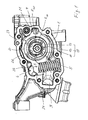
- FIG. 1 shows a rotary pump, for example in vane-type.
- the rotary pump is shown in a side view of a housing 1 of the pump. A cover of the housing 1 is removed, so that the functional components of the rotary pump can be seen.
- the housing 1 forms side walls of a delivery chamber 2, in which a delivery rotor 10 about an axis of rotation R 10 rotatable is arranged.
- the housing 1 has an inlet 3 and an outlet 4 for a fluid to be conveyed, for example engine lubricating oil.
- the delivery chamber 2 includes a low pressure side and a high pressure side. In a rotary drive of the conveyor rotor 10 in the drawn direction of rotation, clockwise, fluid flows through the inlet 3 on the low pressure side in the delivery chamber 2 and is ejected by increasing the pressure on the high pressure side and discharged via the outlet 4.
- the conveyor rotor 10 is an impeller with a central rotor structure 11 with respect to the axis of rotation R 10 and vanes 12 distributed over the circumference of the rotor structure 11.
- the vanes 12 are in slots 13 of the rotor structure 11 which are open to the outer periphery of the rotor structure 11 in the radial or at least in the Slidably guided substantially radial direction slidably.
- the rotor structure 11 is rotatably connected to a rotatable shaft about the axis of rotation R 10 in a form-fitting based joining engagement.
- a joining surface which may be shaped in particular in the manner of a toothing.
- the joining surface is preferably shaped so that the rotor structure 11 can be pushed with its joining surface axially on the shaft.
- the conveyor rotor 10 is surrounded at its outer periphery by a setting structure 20, which is exemplified as an adjusting ring.
- a setting structure 20 which is exemplified as an adjusting ring.
- the axis of rotation R 10 of the conveyor rotor 10 is arranged eccentrically to a parallel central axis of the actuator structure 20, so that the delivery rotor 10 and the adjusting ring 20 formed conveying cells upon rotation of the delivery rotor 10 on the low-pressure side of the delivery chamber 2 in the direction of rotation increase and reduce again on the high-pressure side. Because of this with the speed of the conveyor rotor 10 periodic increase and decrease in the delivery cells, the fluid from the low pressure side to the high pressure side and there promoted with increased pressure through the outlet 4.
- the so-called specific delivery volume can be adjusted. If the fluid is a liquid and thus incompressible to a good approximation, the absolute delivery volume is directly proportional to the speed of the delivery rotor 10. For compressible fluids, such as air, the relationship between flow rate and speed is not linear, but the absolute flow rate or mass also increases with the speed.
- the specific delivery volume depends on the eccentricity, ie the distance between the central axis of the adjusting structure 20 and the axis of rotation R 10 of the conveyor rotor 10.
- the adjusting structure 20 is movably arranged in the housing 1, for example pivotable about a pivot axis R 20 .
- a modified actuator structure in the housing 1 can also be arranged linearly movable.
- a mobility transverse to the axis of rotation R 10 of the conveyor rotor 10 is preferred.
- an axial adjustability would also be conceivable by which an axial width of the delivery cells can be adjusted.
- a pivot bearing region of the actuating structure 20 is designated by 21.
- the pivot bearing is designed as a sliding bearing by the adjusting structure 20 is in its pivot bearing portion 21 with a mating surface of the housing 1 directly in sliding contact.
- the adjusting structure 20 is acted upon by a control fluid pressure acting in the direction of adjustment S.
- This control pressure counteracts a restoring force in the opposite direction.
- the restoring force is generated by a spring device with one or more mechanical spring members, in the embodiment a single spring member 5.
- the spring member 5 is designed and arranged as a helical compression spring.
- a control pressure chamber 6 is formed in the housing 1, into which the control fluid can be introduced to exert on the actuator structure action region 23 and via this on the actuator structure 20 a force acting in the direction of adjustment S force.
- the restoring force likewise acts directly on the adjusting structure-influencing region 23.
- the control pressure chamber 6 is supplied with the pressure fluid delivered by the rotary pump to pressurize the actuator structure 20 in the direction of adjustment S with the control fluid pressure.
- the adjustment direction S is selected such that the eccentricity between the conveying rotor 10 and the adjusting structure 20 and thereby the specific delivery volume decreases when the adjusting structure 20 moves in the direction of adjustment S.
- the adjusting structure 20 forms with the housing 1 a sealing gap which separates the control pressure chamber 6 in the direction of adjustment S from the low-pressure region.
- a sealing element for better sealing of the sealing gap arranged.
- the sealing element is arranged in a receptacle 24 of the adjusting structure 20.
- the adjusting structure 20 and / or the rotor structure 11 are or are in each case composite material structures which consist entirely or at least partially of plastic. However, they are made of at least two materials that differ in terms of their chemical composition, optionally also in terms of aggregates.
- the adjusting structure 20 has a molding area 25 made of plastic and a functional area 26 made of a functional material whose chemical composition differs from the plastic of the molding area 25.
- the functional material may be another plastic or in particular a metal or a metal alloy. It is preferably steel.
- the functional area 26 can advantageously be a cast or sintered body.
- the functional area 26 is ring, sleeve or tubular. It may have an at least substantially smooth surface, in particular a smooth inner circumferential surface.
- the functional area 26 is embedded in the molding area 25.
- the molding area 25 further surrounds the functional area 26 over its entire outer circumference.
- the molding area 25 surrounds the functional area 26 at both axial ends.
- the functional region 26 is embedded in a groove-shaped or trough-shaped depression 28, which circulates on the inner circumference of the molding region 25.
- the molding region 25 encloses the functional region 26 over its outer circumference and axially correspondingly on both sides, so that the molding region 25 and the functional region 26 are connected in a form-fitting, fixed manner relative to one another in an axially immovable manner. A relative movement in the circumferential direction is prevented by a correspondingly firm grip of the functional area 26.
- Forming area 25 and functional area 26 together form the smooth inner peripheral surface 27 of the adjusting structure 20 as a sliding surface.
- the molding area 25 and the functional area 26 advantageously already form the complete actuator structure 20 alone.
- the functional area 26 forms an insert or insert.
- the functional area 26 can, as already mentioned, be a steel insert or another metallic insert or else a plastic insert.
- the functional area 26 is sufficiently rigid that it serves as supporting and / or stiffening body for the forming area 25 within the adjusting structure 20, ie the forming area 25 can be supported on the functional area 26 and / or the shape retention of the adjusting structure 20 can be improved during pump operation ,
- the functional region 26 may be made of a sliding material or coated with a sliding material instead or in combination with a support or stiffening function, wherein the sliding material has the same or preferably a lower coefficient of friction with respect to the sliding friction and preferably also with respect to the static friction the plastic of the molding area 25 may have.
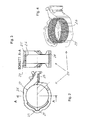
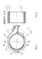
- FIGS. 5 and 6 show a composite material structure of a second embodiment.
- the adjusting structure 20 also differs from the first exemplary embodiment only in that the functional area 26 extends over the entire axial width of the adjusting structure 20 and thus alone forms the inner peripheral surface 27, via which the wings 12 of the conveyor rotor 10 with rotary drive of the conveyor rotor 10.
- the functional area 26 is annular, sleeve or tubular with a small wall thickness compared to the inner diameter.
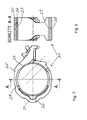
- a third embodiment of a composite material structure 20, again the adjusting structure 20, is in the FIGS. 7 and 8 shown.
- the functional region 26 also extends over the entire axial width of the actuating structure 20 in the third exemplary embodiment.
- the functional region 26 differs from that of the second exemplary embodiment by a radial projection 29 provided on the outer circumference and into a groove-shaped depression 28 of the molding region 25 engages and thereby secures the functional area 26 on the molding area 25 axially in addition to the solid wrap around the mold area 25.
- the functional area 26 in the third embodiment corresponds to the functional area 26 of the second embodiment.
- Recess 28 and Abragung 29 may be completely or only partially formed circumferentially and interlock.
- the functional region 26 encloses the forming region 25 axially on both sides, in that the functional region 26, which essentially forms a thin-walled tube, has a flange 29 protruding outwards at its two axial ends advantageously completely circulate. Axially between the two flanges 29 The functional region 26 accordingly forms a depression 28 into which the molding region 25 engages and which preferably fills the molding region 25. The two flanges 29 secure the functional area 26 axially.
- the molding area 25 surrounds the axial section of the functional area 26, which extends between the flanges 29, in a force-locking manner.
- a frictional connection can, as in the other exemplary embodiments, also occur when the functional insert 26 is reshaped with the molding area plastic due to the solidification of the plastic of the molding area 25.
- the functional area 26 can, as in the previous exemplary embodiments, serve as a support and / or stiffening structure for the molding area 25.
- the functional region 26 forms the inner peripheral surface 27 and is therefore preferably made of a sliding material having the good sliding properties and wear resistance required for pump operation.
- the comments on the other exemplary embodiments apply equally to the fourth exemplary embodiment.
- the functional area 26 can be provided in particular as an insert or insert body and formed with the plastic of the molding area, preferably encapsulated.
- FIG. 11 is the functional area 26 removed from the composite material structure 20 shown alone.
- the functional region 26, as in the exemplary embodiments explained above, can in particular form a metal or plastic insert, preferably a steel insert, within the composite material structure 20.
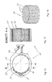
- FIGS. 12 and 13 a fifth exemplary embodiment of a setting structure 20 formed as a composite material structure is illustrated.
- the actuator structure 20 of the fifth embodiment is composed of only two areas, the molding area 25 made of plastic and the functional area 26 of functional material.
- the functional region 26, as in the embodiments described above, is annular, sleeve-shaped or tubular with a smaller wall thickness compared to the inner diameter. It has a plurality of passages 30 distributed over its circumference.
- the functional area 26 can also be referred to as a perforated hollow structure.
- the passages 30 are penetrated by the plastic of the molding area 25, so that the molding area 25 and the functional area 26 are anchored to one another and a particularly intimate positive connection is obtained.
- the sleeve, ring or tubular insert 26, which forms the functional region 26 in the composite material structure 20, is in FIG. 14 detached from the composite material structure shown alone.
- the functional area 26, or the structural part or insert forming it can be inserted into a mold and can be inserted with the plastic of the mold area 25 deformed, preferably overmoulded.
- the plastic of the molding area 25 preferably penetrates into the passages 30 and thereby anchors the functional area 26 on the molding area 25.
- the functional area 26 may support and / or stiffen the molding area 25.
- the functional areas 26 of the first to fifth embodiments can be surrounded on the outside and inside by the plastic of the molding area 25 or can also be completely embedded in the plastic of the molding area 25, so that they do not have a sliding function in the modifications, but merely support and / or stiffening function have the composite material structure 20.
- the inner circumferential surface 27 serving as a sliding surface is formed by the plastic of the molding area 25 in the modifications.
- the functional regions 26 of the first to fourth exemplary embodiments may additionally have passages, such as the passages 30, in order to additionally obtain an anchoring of the regions 25 and 26 to one another in addition to the positive connection existing in the respective exemplary embodiment.
- the functional area 26 in all examples may have an outwardly projecting rib or at one or both axial ends a protruding flange and / or not extend over the entire axial length of the actuator structure 20, but approximately as in the first embodiment, the local functional area 26th be embedded axially.
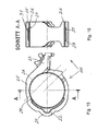
- FIGS. 15 and 16 show a sixth embodiment of a formed as a composite material structure actuator structure 20.
- This actuator structure 20 includes a mold portion 25, which forms the bearing portion 21 with the sliding bearing surface 22 and on the opposite side of the Einwirk Scheme 23 in one piece as in the embodiments described above.
- the adjusting structure 20 furthermore has a first functional region 26 made of a first functional material and a further, second functional region 31 made of a second functional material.
- the first and also the second functional material differ from the plastic of the molding area 25 at least with regard to their chemical composition. They also differ in preferred embodiments with each other in the chemical composition.
- the functional materials are plastics, they can differ from each other, at least in terms of aggregates.
- one functional material may be a fiber-reinforced plastic and the other may be a plastic without fiber reinforcement or a plastic with fibers of another type.
- both functional materials are formed as plastics, then, for example, the plastic forming the functional region 26 may contain carbon fibers in order to obtain good sliding properties for the inner circumferential surface 27, which it alone forms or at least forms as a sliding surface.
- the functional material of the functional region 31 can be, for example, glass-fiber reinforced or consist of a plastic which is more dimensionally stable than the functional material of the functional region 26.
- the functional region 26 is plastic or metal with good sliding properties and sufficiently high wear resistance
- the second functional region 31 is made of metal, preferably steel.
- the first functional region 26 and / or the second functional region 31 is or are each preferably provided as a prefabricated insert, advantageously made of a metallic material or plastic.
- the second functional region 31 is used in preferred embodiments as a support and / or stiffening structure and may in particular in such embodiments of metallic material, preferably steel exist. It can be provided for example as a prefabricated sintered body or cast body.
- the first functional region 26 and / or in particular the second functional region 31 may or may each have passages, such as passages such as the passages 30 of the previous embodiment, and correspondingly be penetrated by the plastic material in the primary molding of the mold region 25 in order to obtain a more intimate positive connection.
- the two functional regions 26 and 31 can be provided in particular as inserts, inserted into a mold, for example a plastic injection mold, and shaped, preferably encapsulated, with the plastic of the mold region 25.
- the functional area 26 and also the further functional area 31 are each formed at least essentially as a hollow profile structure and surround or surround the remaining free internal cross section of the actuating structure 20 in which the conveyor rotor 10 is arranged.
- a functional area made of a material that, as described, differs from the plastic of the molding area 25 can instead also form another area of the positioning structure 20.
- the sliding surface 22 of the bearing area 21 or the entire bearing area 21 can be formed as such a functional area from a functional material.
- the functional material of such a functional area is preferably a sliding material with good sliding properties and sufficient wear resistance for the sliding friction loads occurring in the pivot bearing of the adjusting structure 20.
- Such a functional area may additionally or in principle also be provided instead of the functional areas 26 and 31 explained.
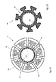
- FIGS. 17 and 18 is a composite material structure of a seventh embodiment shown, which can form the rotor structure 11 in the rotary pump and is accordingly provided with the reference numeral "11".
- the rotor structure 11 has a passage in the central area, which is enclosed by an inner peripheral surface.
- the inner peripheral surface is formed as a joining surface 19 for producing a rosununbeweglichen connection with a drive shaft of the rotary pump.
- the peripheral surface or joining surface 19 is therefore not circular. In the exemplary embodiment, it is shaped in the manner of an internal toothing.
- the outer shape of the rotor structure 11 may be formed as conventional rotor structures of vane pumps.
- the rotor structure 11 is designed as a composite material structure and accordingly comprises a molding area 15 made of a plastic and a functional area 16 made of a functional material of a different chemical composition than the plastic of the molding area 15.
- the functional material may in particular be a plastic or a metallic material, preferably a steel.
- the functional area 16 advantageously as a prefabricated insert or as a prefabricated EinlegeMech provided and formed with the plastic of the molding area 15, preferably encapsulated and in particular encapsulated.
- the functional region 16 forms the joining surface 19, thus serving as joining region, and supports and stiffens the molding region 15.
- the functional region 16 has indentations 18 distributed over its circumference, into which plastic has penetrated in the original molding of the molding region 15.
- the recesses 18 are preferably pocket-shaped widened radially inwardly, so that the plastic of the molding area 15 surrounds the functional area 16 not only on the circumference outside, but also engages behind the openings of the pockets or recesses 18 from the outer periphery, whereby a Anchoring effect is achieved.
- the wings 12 ( FIG. 1 ) slide in the slots 13 during retraction and extension of the lateral slot walls, which form corresponding sliding surfaces 14 for the wings 12.
- the slots 13 are formed in the molding area 15 so that the plastic of the molding area 15 forms the sliding surfaces 14.
- the functional area 16 has a central hollow profile, the inner peripheral surface of which is the joining surface 19.
- the functional area 16 also has projections which protrude radially outward from the hollow profile and surround the slots 13 in the area of the respective slot base. Each adjacent Abragept form the depressions 18 between them.
- FIGS. 19 and 20 show an eighth embodiment of a composite material structure again using the example of the rotor structure 11.
- the outer shape of the rotor structure 11 of the eighth embodiment corresponds to that of the seventh embodiment.
- the rotor structure 11 forms, as in the seventh embodiment, the joining surface 19 for the positive-fit joint with the drive shaft and supports and stiffens the molding area 15.
- the functional area 16 also forms the circumferentially leading and trailing sidewalls of the slots 13 for the wings 12 in the form of the sliding surfaces 17.
- the functional material forming the functional region 16 is therefore expediently a sliding material with good sliding properties and sufficiently high wear resistance.
- the functional area 16 has short projections extending in the circumferential direction, so that the plastic of the molding area 15, which has penetrated into the depressions of the functional area 16 remaining between the slots 13, engages behind the projections of the functional area 16 and the anchoring thereby improved.
- the functional area 16 extends to the outer circumference of the rotor structure 11.
- the mold portion 15 projects beyond the functional region 16 in the axial direction, so that the molding region 15 as in the seventh embodiment and the rest
- the molding area 25 of the actuator structures 20 is formed as a single contiguous area.
- FIGS. 21 and 22 show a ninth embodiment of a composite material structure using the example of the rotor structure 11.
- the outer shape of the rotor structure 11 of the ninth embodiment corresponds to those of the seventh and eighth embodiments.
- the rotor structure 11 forms the joining surface 19 for the positive-fit connection with the drive shaft and supports and stiffens the forming region 15.
- the forming region 15 forms the circumferentially leading and trailing side walls of the slots 13 for the wings
- the functional region 16 comprises a hollow profile with a joining surface 19 formed as an inner circumferential surface.
- protrusions protrude outward from the hollow profile and into the plastic of the molding region 15, resulting in large , in the radial direction extending pressure surfaces for transmitting the torque can be obtained.
- the functional material does not clothe the slots 13, not even in the slot bottom, as in the seventh embodiment.
- the Abragonne are offset from the slots 13 in the circumferential direction. They each protrude between adjacent slots 13 into the molding area 15, which surrounds the functional area 16.
- the projections broaden radially outwardly mushroom-shaped, so that the molding area 15 and the functional area 16, as viewed from the outer circumference and from the joining surface 19, engage behind one another.
- the plastic of the molding area 15 surrounds the Abragept on the outer circumference and also on the forward and trailing sides during rotational movement. The projections stabilize the molding area and subdivide it into smaller subregions, which improves the dimensional stability of the rotor structure 11 over the operating temperature range.
- the functional region 16 advantageously as a prefabricated insert, preferably made of metal or plastic and particularly preferably made of steel, and formed with the plastic of the molding area 15, advantageously encapsulated and in particular encapsulated.
Landscapes
- Engineering & Computer Science (AREA)
- Mechanical Engineering (AREA)
- General Engineering & Computer Science (AREA)
- Details And Applications Of Rotary Liquid Pumps (AREA)
- Rotary Pumps (AREA)
- Structures Of Non-Positive Displacement Pumps (AREA)
- Applications Or Details Of Rotary Compressors (AREA)
Applications Claiming Priority (1)
| Application Number | Priority Date | Filing Date | Title |
|---|---|---|---|
| DE102014102643.8A DE102014102643A1 (de) | 2014-02-27 | 2014-02-27 | Rotationspumpe mit Kunststoffverbundstruktur |
Publications (1)
| Publication Number | Publication Date |
|---|---|
| EP2913530A1 true EP2913530A1 (fr) | 2015-09-02 |
Family
ID=52574062
Family Applications (1)
| Application Number | Title | Priority Date | Filing Date |
|---|---|---|---|
| EP15156205.5A Withdrawn EP2913530A1 (fr) | 2014-02-27 | 2015-02-23 | Pompe rotative dotée d'une structure composite en plastique |
Country Status (7)
| Country | Link |
|---|---|
| US (1) | US9920756B2 (fr) |
| EP (1) | EP2913530A1 (fr) |
| JP (1) | JP2016027248A (fr) |
| KR (1) | KR20150101960A (fr) |
| CN (1) | CN104879299A (fr) |
| DE (1) | DE102014102643A1 (fr) |
| MX (1) | MX2015002466A (fr) |
Cited By (2)
| Publication number | Priority date | Publication date | Assignee | Title |
|---|---|---|---|---|
| WO2017066277A1 (fr) * | 2015-10-12 | 2017-04-20 | Sabic Global Technologies B.V. | Pompe à huile de moteur |
| DE102015223452A1 (de) * | 2015-11-26 | 2017-06-01 | Volkswagen Aktiengesellschaft | Flügelzellenpumpe |
Families Citing this family (9)
| Publication number | Priority date | Publication date | Assignee | Title |
|---|---|---|---|---|
| DE102016105247A1 (de) * | 2016-03-21 | 2017-09-21 | Schwäbische Hüttenwerke Automotive GmbH | Förderelement für eine rotationspumpe |
| DE202018103580U1 (de) * | 2017-06-27 | 2018-09-05 | O.M.P. Officine Mazzocco Pagnoni S.R.L. | Wasserpumpe |
| DE102017117787A1 (de) * | 2017-08-04 | 2019-02-07 | Schwäbische Hüttenwerke Automotive GmbH | Verstellbare Außenzahnradpumpe |
| DE102017128787A1 (de) * | 2017-12-04 | 2019-06-06 | Schwäbische Hüttenwerke Automotive GmbH | Rotationspumpe |
| JP7295613B2 (ja) * | 2018-04-09 | 2023-06-21 | Kyb株式会社 | 流体圧回転機 |
| KR102135628B1 (ko) * | 2019-03-26 | 2020-07-20 | (주)한국정밀 | 밸런스샤프트모듈의 오일펌프용 분말소결금속형 로터 회전자의 제조방법 |
| EP3973186A1 (fr) * | 2019-05-23 | 2022-03-30 | Pierburg Pump Technology GmbH | Pompe à lubrifiant à cylindrée variable |
| CN113994096B (zh) * | 2019-05-23 | 2023-08-01 | 皮尔伯格泵技术有限责任公司 | 可变排量润滑剂泵 |
| RU2756825C1 (ru) * | 2020-05-06 | 2021-10-06 | Сергей Николаевич Филиппов | Роторно-пластинчатое устройство для преобразования возвратно-поступательного движения во вращательное, без кривошипно-шатунного механизма |
Citations (6)
| Publication number | Priority date | Publication date | Assignee | Title |
|---|---|---|---|---|
| US20040219036A1 (en) * | 2003-05-01 | 2004-11-04 | Hypro Corporation | Plastic rotor for pumps |
| WO2004109110A1 (fr) * | 2003-05-23 | 2004-12-16 | Luk Automobiltechnik Gmbh & Co. Kg | Pompe a engrenages |
| DE102011014591A1 (de) * | 2011-03-21 | 2012-09-27 | Volkswagen Ag | Flügelzellenpumpe mit Pumpensteuerring |
| DE102011086175B3 (de) | 2011-11-11 | 2013-05-16 | Schwäbische Hüttenwerke Automotive GmbH | Rotationspumpe mit verbesserter Abdichtung |
| DE102008036273B4 (de) | 2008-08-04 | 2013-09-26 | Schwäbische Hüttenwerke Automotive GmbH & Co. KG | Rotationskolbenpumpe mit Taschen für Schmiermittel |
| EP2735740A1 (fr) * | 2012-11-27 | 2014-05-28 | Pierburg Pump Technology GmbH | Pompe à ailettes à cylindrée variable pour lubrifiant |
Family Cites Families (15)
| Publication number | Priority date | Publication date | Assignee | Title |
|---|---|---|---|---|
| US4028021A (en) * | 1975-12-08 | 1977-06-07 | Curtiss-Wright Corporation | Rotary trochoidal compressor with compressible sealing |
| US5073434A (en) | 1989-12-29 | 1991-12-17 | Xerox Corporation | Ionographic imaging system |
| JPH0651589U (ja) * | 1992-12-18 | 1994-07-15 | 政人 牧野 | 回転装置用吸震形ボス |
| CN2284870Y (zh) | 1996-06-26 | 1998-06-24 | 蒋铭华 | 低速高效工程塑料节能泵 |
| CN2420360Y (zh) | 1999-12-22 | 2001-02-21 | 吉开平 | 用于建筑房屋的无机复合夹芯板材 |
| US6821099B2 (en) * | 2002-07-02 | 2004-11-23 | Tilia International, Inc. | Rotary pump |
| WO2004109111A1 (fr) | 2003-05-26 | 2004-12-16 | Luk Automobiltechnik Gmbh & Co. Kg | Pompe à cellules en ailettes à pot en tôle d'acier emboutie |
| JP4647239B2 (ja) * | 2004-05-14 | 2011-03-09 | 本田技研工業株式会社 | トロコイド式ポンプのアウターロータおよびその製造方法 |
| DE112007000514T5 (de) * | 2006-03-01 | 2009-05-07 | Magna Powertrain Inc., Concord | Flügelpumpe mit reduziertem Rotoranordnungsdurchmesser |
| ITTO20060263A1 (it) | 2006-04-11 | 2007-10-12 | Vhit Spa | Rotore per pompa a palette in materia plastica rinforzata da lamine metalliche |
| DE502006008468D1 (de) * | 2006-10-10 | 2011-01-20 | Joma Polytec Gmbh | Flügelzellenmaschine, insbesondere flügelzellenpumpe |
| CN201148018Y (zh) | 2008-01-04 | 2008-11-12 | 安藤产品设计有限公司 | 玻璃纤维塑料与金属材料的复合结构 |
| US7997959B2 (en) * | 2008-02-16 | 2011-08-16 | Hutchins Manufacturing Company | Pneumatic tool having a rotor with a wear-resistant vane slot |
| KR101017409B1 (ko) | 2008-08-13 | 2011-02-28 | (주) 시.알. 씨스템 | 베인 진공펌프 |
| DE102012214503B4 (de) | 2012-08-14 | 2017-10-12 | Schwäbische Hüttenwerke Automotive GmbH | Rotationspumpe mit verstellbarem Fördervolumen, insbesondere zum Verstellen einer Kühlmittelpumpe |
-
2014
- 2014-02-27 DE DE102014102643.8A patent/DE102014102643A1/de not_active Withdrawn
-
2015
- 2015-02-16 JP JP2015027773A patent/JP2016027248A/ja active Pending
- 2015-02-16 US US14/622,996 patent/US9920756B2/en not_active Expired - Fee Related
- 2015-02-23 EP EP15156205.5A patent/EP2913530A1/fr not_active Withdrawn
- 2015-02-25 MX MX2015002466A patent/MX2015002466A/es unknown
- 2015-02-27 KR KR1020150028534A patent/KR20150101960A/ko not_active Ceased
- 2015-02-27 CN CN201510090063.5A patent/CN104879299A/zh active Pending
Patent Citations (6)
| Publication number | Priority date | Publication date | Assignee | Title |
|---|---|---|---|---|
| US20040219036A1 (en) * | 2003-05-01 | 2004-11-04 | Hypro Corporation | Plastic rotor for pumps |
| WO2004109110A1 (fr) * | 2003-05-23 | 2004-12-16 | Luk Automobiltechnik Gmbh & Co. Kg | Pompe a engrenages |
| DE102008036273B4 (de) | 2008-08-04 | 2013-09-26 | Schwäbische Hüttenwerke Automotive GmbH & Co. KG | Rotationskolbenpumpe mit Taschen für Schmiermittel |
| DE102011014591A1 (de) * | 2011-03-21 | 2012-09-27 | Volkswagen Ag | Flügelzellenpumpe mit Pumpensteuerring |
| DE102011086175B3 (de) | 2011-11-11 | 2013-05-16 | Schwäbische Hüttenwerke Automotive GmbH | Rotationspumpe mit verbesserter Abdichtung |
| EP2735740A1 (fr) * | 2012-11-27 | 2014-05-28 | Pierburg Pump Technology GmbH | Pompe à ailettes à cylindrée variable pour lubrifiant |
Cited By (3)
| Publication number | Priority date | Publication date | Assignee | Title |
|---|---|---|---|---|
| WO2017066277A1 (fr) * | 2015-10-12 | 2017-04-20 | Sabic Global Technologies B.V. | Pompe à huile de moteur |
| CN108603408A (zh) * | 2015-10-12 | 2018-09-28 | 沙特基础工业全球技术公司 | 发动机油泵 |
| DE102015223452A1 (de) * | 2015-11-26 | 2017-06-01 | Volkswagen Aktiengesellschaft | Flügelzellenpumpe |
Also Published As
| Publication number | Publication date |
|---|---|
| CN104879299A (zh) | 2015-09-02 |
| MX2015002466A (es) | 2015-08-26 |
| KR20150101960A (ko) | 2015-09-04 |
| JP2016027248A (ja) | 2016-02-18 |
| US9920756B2 (en) | 2018-03-20 |
| DE102014102643A1 (de) | 2015-08-27 |
| US20150240806A1 (en) | 2015-08-27 |
Similar Documents
| Publication | Publication Date | Title |
|---|---|---|
| EP2913530A1 (fr) | Pompe rotative dotée d'une structure composite en plastique | |
| EP1448894B1 (fr) | Pompe hybride a amorcage automatique | |
| DE3333647C2 (de) | Schmiermittelpumpe für die Druckerzeugung bei einem druckumlaufgeschmierten Verbrennungsmotor | |
| DE102008036273B4 (de) | Rotationskolbenpumpe mit Taschen für Schmiermittel | |
| EP3034780A1 (fr) | Pompe rotative comprenant une structure compacte destinee au reglage d'un volume d'alimentation | |
| WO2014015959A1 (fr) | Roue à aubes destinée à une machine à fluide | |
| EP3333381B1 (fr) | Dispositif hydraulique comprenant un élément d'étanchéité | |
| DE102014107735B4 (de) | Flügel mit axialer Abdichtung | |
| WO2000047899A1 (fr) | Pompe regenerative | |
| EP1766237B1 (fr) | Pompe a vide a une ailette | |
| EP2761184A2 (fr) | Pompe à engrenages intérieurs | |
| DE102009017452B4 (de) | Ölförderpumpe | |
| EP2513483B1 (fr) | Pompe à carburant | |
| DE102017128787A1 (de) | Rotationspumpe | |
| DE10040711C2 (de) | Flügelzellenpumpe | |
| DE102016118627B4 (de) | Pumpe für flüssige Fördermedien mit schwimmender Rotorlagerung | |
| DE102006016244A1 (de) | Rotorpumpe | |
| AT505061B1 (de) | Drehschieberpumpe | |
| DE102013221567A1 (de) | Pendelschieberzellenpumpe zur Förderung eines Fluides | |
| EP2342465B1 (fr) | Soufflante à canal latéral, en particulier turbine secondaire pour un moteur à combustion interne | |
| DE102016121388A1 (de) | Optimierter Rotor für eine Rotationspumpe | |
| DE102014220766B4 (de) | Pendelschiebermaschine | |
| DE10230407B4 (de) | Innenzahnradpumpe mit variabler Abdichtung | |
| DE102010020574A1 (de) | Strömungsführende Einrichtung | |
| DE102010064193A1 (de) | Innenzahnradpumpe |
Legal Events
| Date | Code | Title | Description |
|---|---|---|---|
| PUAI | Public reference made under article 153(3) epc to a published international application that has entered the european phase |
Free format text: ORIGINAL CODE: 0009012 |
|
| AK | Designated contracting states |
Kind code of ref document: A1 Designated state(s): AL AT BE BG CH CY CZ DE DK EE ES FI FR GB GR HR HU IE IS IT LI LT LU LV MC MK MT NL NO PL PT RO RS SE SI SK SM TR |
|
| AX | Request for extension of the european patent |
Extension state: BA ME |
|
| 17P | Request for examination filed |
Effective date: 20160219 |
|
| RBV | Designated contracting states (corrected) |
Designated state(s): AL AT BE BG CH CY CZ DE DK EE ES FI FR GB GR HR HU IE IS IT LI LT LU LV MC MK MT NL NO PL PT RO RS SE SI SK SM TR |
|
| 17Q | First examination report despatched |
Effective date: 20170919 |
|
| STAA | Information on the status of an ep patent application or granted ep patent |
Free format text: STATUS: THE APPLICATION IS DEEMED TO BE WITHDRAWN |
|
| 18D | Application deemed to be withdrawn |
Effective date: 20180330 |