EP2913548A1 - Roulement - Google Patents
Roulement Download PDFInfo
- Publication number
- EP2913548A1 EP2913548A1 EP13852223.0A EP13852223A EP2913548A1 EP 2913548 A1 EP2913548 A1 EP 2913548A1 EP 13852223 A EP13852223 A EP 13852223A EP 2913548 A1 EP2913548 A1 EP 2913548A1
- Authority
- EP
- European Patent Office
- Prior art keywords
- hardness
- mass
- bearing
- raceway surface
- less
- Prior art date
- Legal status (The legal status is an assumption and is not a legal conclusion. Google has not performed a legal analysis and makes no representation as to the accuracy of the status listed.)
- Withdrawn
Links
- 238000005096 rolling process Methods 0.000 title claims abstract description 44
- 238000010438 heat treatment Methods 0.000 claims abstract description 62
- 229910001566 austenite Inorganic materials 0.000 claims abstract description 32
- 229910000831 Steel Inorganic materials 0.000 claims abstract description 29
- 239000000463 material Substances 0.000 claims abstract description 29
- 239000010959 steel Substances 0.000 claims abstract description 29
- 230000006698 induction Effects 0.000 claims description 41
- 230000000717 retained effect Effects 0.000 claims description 30
- XEEYBQQBJWHFJM-UHFFFAOYSA-N Iron Chemical compound [Fe] XEEYBQQBJWHFJM-UHFFFAOYSA-N 0.000 claims description 10
- 229910052742 iron Inorganic materials 0.000 claims description 5
- 239000012535 impurity Substances 0.000 claims description 4
- 238000000137 annealing Methods 0.000 abstract description 6
- 230000000052 comparative effect Effects 0.000 description 54
- 239000010410 layer Substances 0.000 description 30
- 230000000171 quenching effect Effects 0.000 description 19
- 229910052799 carbon Inorganic materials 0.000 description 14
- OKTJSMMVPCPJKN-UHFFFAOYSA-N Carbon Chemical compound [C] OKTJSMMVPCPJKN-UHFFFAOYSA-N 0.000 description 13
- 230000000694 effects Effects 0.000 description 9
- 230000008859 change Effects 0.000 description 8
- 238000010791 quenching Methods 0.000 description 8
- 239000000126 substance Substances 0.000 description 7
- 230000006835 compression Effects 0.000 description 6
- 238000007906 compression Methods 0.000 description 6
- 238000010276 construction Methods 0.000 description 6
- 238000005520 cutting process Methods 0.000 description 6
- 238000000034 method Methods 0.000 description 6
- 229910045601 alloy Inorganic materials 0.000 description 4
- 239000000956 alloy Substances 0.000 description 4
- 238000007654 immersion Methods 0.000 description 4
- 238000005461 lubrication Methods 0.000 description 4
- 239000000203 mixture Substances 0.000 description 4
- 239000003921 oil Substances 0.000 description 4
- 238000012360 testing method Methods 0.000 description 4
- 229910000954 Medium-carbon steel Inorganic materials 0.000 description 3
- QVGXLLKOCUKJST-UHFFFAOYSA-N atomic oxygen Chemical compound [O] QVGXLLKOCUKJST-UHFFFAOYSA-N 0.000 description 3
- 238000005255 carburizing Methods 0.000 description 3
- 229910052804 chromium Inorganic materials 0.000 description 3
- 230000006866 deterioration Effects 0.000 description 3
- 238000007373 indentation Methods 0.000 description 3
- 229910000734 martensite Inorganic materials 0.000 description 3
- 239000001301 oxygen Substances 0.000 description 3
- 229910052760 oxygen Inorganic materials 0.000 description 3
- 102220097517 rs876659265 Human genes 0.000 description 3
- 229910000851 Alloy steel Inorganic materials 0.000 description 2
- IJGRMHOSHXDMSA-UHFFFAOYSA-N Atomic nitrogen Chemical compound N#N IJGRMHOSHXDMSA-UHFFFAOYSA-N 0.000 description 2
- 238000002441 X-ray diffraction Methods 0.000 description 2
- 238000005256 carbonitriding Methods 0.000 description 2
- 238000011161 development Methods 0.000 description 2
- 238000010348 incorporation Methods 0.000 description 2
- 230000001050 lubricating effect Effects 0.000 description 2
- 239000010687 lubricating oil Substances 0.000 description 2
- 238000005259 measurement Methods 0.000 description 2
- 229910052750 molybdenum Inorganic materials 0.000 description 2
- 229910052759 nickel Inorganic materials 0.000 description 2
- 239000000843 powder Substances 0.000 description 2
- 238000012545 processing Methods 0.000 description 2
- 230000009467 reduction Effects 0.000 description 2
- 239000002344 surface layer Substances 0.000 description 2
- 229910000677 High-carbon steel Inorganic materials 0.000 description 1
- UFHFLCQGNIYNRP-UHFFFAOYSA-N Hydrogen Chemical compound [H][H] UFHFLCQGNIYNRP-UHFFFAOYSA-N 0.000 description 1
- 229910001209 Low-carbon steel Inorganic materials 0.000 description 1
- 238000013459 approach Methods 0.000 description 1
- 229910001563 bainite Inorganic materials 0.000 description 1
- 230000003749 cleanliness Effects 0.000 description 1
- 238000004090 dissolution Methods 0.000 description 1
- 238000009826 distribution Methods 0.000 description 1
- 230000002708 enhancing effect Effects 0.000 description 1
- 239000007789 gas Substances 0.000 description 1
- 239000004519 grease Substances 0.000 description 1
- 239000001257 hydrogen Substances 0.000 description 1
- 229910052739 hydrogen Inorganic materials 0.000 description 1
- 230000002401 inhibitory effect Effects 0.000 description 1
- 239000000314 lubricant Substances 0.000 description 1
- 238000003754 machining Methods 0.000 description 1
- 229910052748 manganese Inorganic materials 0.000 description 1
- 238000004519 manufacturing process Methods 0.000 description 1
- 239000011159 matrix material Substances 0.000 description 1
- 230000007246 mechanism Effects 0.000 description 1
- 239000002184 metal Substances 0.000 description 1
- 229910052751 metal Inorganic materials 0.000 description 1
- 238000012986 modification Methods 0.000 description 1
- 230000004048 modification Effects 0.000 description 1
- 229910052757 nitrogen Inorganic materials 0.000 description 1
- 229910001562 pearlite Inorganic materials 0.000 description 1
- 230000000704 physical effect Effects 0.000 description 1
- 238000005498 polishing Methods 0.000 description 1
- 238000001556 precipitation Methods 0.000 description 1
- 230000008569 process Effects 0.000 description 1
- 230000002829 reductive effect Effects 0.000 description 1
- 230000000979 retarding effect Effects 0.000 description 1
- 239000007858 starting material Substances 0.000 description 1
- 238000005496 tempering Methods 0.000 description 1
- 230000009466 transformation Effects 0.000 description 1
Images

Classifications
-
- C—CHEMISTRY; METALLURGY
- C21—METALLURGY OF IRON
- C21D—MODIFYING THE PHYSICAL STRUCTURE OF FERROUS METALS; GENERAL DEVICES FOR HEAT TREATMENT OF FERROUS OR NON-FERROUS METALS OR ALLOYS; MAKING METAL MALLEABLE, e.g. BY DECARBURISATION OR TEMPERING
- C21D9/00—Heat treatment, e.g. annealing, hardening, quenching or tempering, adapted for particular articles; Furnaces therefor
- C21D9/40—Heat treatment, e.g. annealing, hardening, quenching or tempering, adapted for particular articles; Furnaces therefor for rings; for bearing races
-
- C—CHEMISTRY; METALLURGY
- C21—METALLURGY OF IRON
- C21D—MODIFYING THE PHYSICAL STRUCTURE OF FERROUS METALS; GENERAL DEVICES FOR HEAT TREATMENT OF FERROUS OR NON-FERROUS METALS OR ALLOYS; MAKING METAL MALLEABLE, e.g. BY DECARBURISATION OR TEMPERING
- C21D1/00—General methods or devices for heat treatment, e.g. annealing, hardening, quenching or tempering
- C21D1/34—Methods of heating
- C21D1/42—Induction heating
-
- C—CHEMISTRY; METALLURGY
- C21—METALLURGY OF IRON
- C21D—MODIFYING THE PHYSICAL STRUCTURE OF FERROUS METALS; GENERAL DEVICES FOR HEAT TREATMENT OF FERROUS OR NON-FERROUS METALS OR ALLOYS; MAKING METAL MALLEABLE, e.g. BY DECARBURISATION OR TEMPERING
- C21D6/00—Heat treatment of ferrous alloys
- C21D6/004—Heat treatment of ferrous alloys containing Cr and Ni
-
- C—CHEMISTRY; METALLURGY
- C21—METALLURGY OF IRON
- C21D—MODIFYING THE PHYSICAL STRUCTURE OF FERROUS METALS; GENERAL DEVICES FOR HEAT TREATMENT OF FERROUS OR NON-FERROUS METALS OR ALLOYS; MAKING METAL MALLEABLE, e.g. BY DECARBURISATION OR TEMPERING
- C21D6/00—Heat treatment of ferrous alloys
- C21D6/005—Heat treatment of ferrous alloys containing Mn
-
- C—CHEMISTRY; METALLURGY
- C21—METALLURGY OF IRON
- C21D—MODIFYING THE PHYSICAL STRUCTURE OF FERROUS METALS; GENERAL DEVICES FOR HEAT TREATMENT OF FERROUS OR NON-FERROUS METALS OR ALLOYS; MAKING METAL MALLEABLE, e.g. BY DECARBURISATION OR TEMPERING
- C21D6/00—Heat treatment of ferrous alloys
- C21D6/008—Heat treatment of ferrous alloys containing Si
-
- C—CHEMISTRY; METALLURGY
- C22—METALLURGY; FERROUS OR NON-FERROUS ALLOYS; TREATMENT OF ALLOYS OR NON-FERROUS METALS
- C22C—ALLOYS
- C22C38/00—Ferrous alloys, e.g. steel alloys
-
- C—CHEMISTRY; METALLURGY
- C22—METALLURGY; FERROUS OR NON-FERROUS ALLOYS; TREATMENT OF ALLOYS OR NON-FERROUS METALS
- C22C—ALLOYS
- C22C38/00—Ferrous alloys, e.g. steel alloys
- C22C38/02—Ferrous alloys, e.g. steel alloys containing silicon
-
- C—CHEMISTRY; METALLURGY
- C22—METALLURGY; FERROUS OR NON-FERROUS ALLOYS; TREATMENT OF ALLOYS OR NON-FERROUS METALS
- C22C—ALLOYS
- C22C38/00—Ferrous alloys, e.g. steel alloys
- C22C38/04—Ferrous alloys, e.g. steel alloys containing manganese
-
- C—CHEMISTRY; METALLURGY
- C22—METALLURGY; FERROUS OR NON-FERROUS ALLOYS; TREATMENT OF ALLOYS OR NON-FERROUS METALS
- C22C—ALLOYS
- C22C38/00—Ferrous alloys, e.g. steel alloys
- C22C38/18—Ferrous alloys, e.g. steel alloys containing chromium
- C22C38/40—Ferrous alloys, e.g. steel alloys containing chromium with nickel
- C22C38/44—Ferrous alloys, e.g. steel alloys containing chromium with nickel with molybdenum or tungsten
-
- F—MECHANICAL ENGINEERING; LIGHTING; HEATING; WEAPONS; BLASTING
- F16—ENGINEERING ELEMENTS AND UNITS; GENERAL MEASURES FOR PRODUCING AND MAINTAINING EFFECTIVE FUNCTIONING OF MACHINES OR INSTALLATIONS; THERMAL INSULATION IN GENERAL
- F16C—SHAFTS; FLEXIBLE SHAFTS; ELEMENTS OR CRANKSHAFT MECHANISMS; ROTARY BODIES OTHER THAN GEARING ELEMENTS; BEARINGS
- F16C33/00—Parts of bearings; Special methods for making bearings or parts thereof
- F16C33/30—Parts of ball or roller bearings
- F16C33/58—Raceways; Race rings
- F16C33/583—Details of specific parts of races
- F16C33/585—Details of specific parts of races of raceways, e.g. ribs to guide the rollers
-
- F—MECHANICAL ENGINEERING; LIGHTING; HEATING; WEAPONS; BLASTING
- F16—ENGINEERING ELEMENTS AND UNITS; GENERAL MEASURES FOR PRODUCING AND MAINTAINING EFFECTIVE FUNCTIONING OF MACHINES OR INSTALLATIONS; THERMAL INSULATION IN GENERAL
- F16C—SHAFTS; FLEXIBLE SHAFTS; ELEMENTS OR CRANKSHAFT MECHANISMS; ROTARY BODIES OTHER THAN GEARING ELEMENTS; BEARINGS
- F16C33/00—Parts of bearings; Special methods for making bearings or parts thereof
- F16C33/30—Parts of ball or roller bearings
- F16C33/58—Raceways; Race rings
- F16C33/62—Selection of substances
-
- F—MECHANICAL ENGINEERING; LIGHTING; HEATING; WEAPONS; BLASTING
- F16—ENGINEERING ELEMENTS AND UNITS; GENERAL MEASURES FOR PRODUCING AND MAINTAINING EFFECTIVE FUNCTIONING OF MACHINES OR INSTALLATIONS; THERMAL INSULATION IN GENERAL
- F16C—SHAFTS; FLEXIBLE SHAFTS; ELEMENTS OR CRANKSHAFT MECHANISMS; ROTARY BODIES OTHER THAN GEARING ELEMENTS; BEARINGS
- F16C33/00—Parts of bearings; Special methods for making bearings or parts thereof
- F16C33/30—Parts of ball or roller bearings
- F16C33/58—Raceways; Race rings
- F16C33/64—Special methods of manufacture
-
- C—CHEMISTRY; METALLURGY
- C21—METALLURGY OF IRON
- C21D—MODIFYING THE PHYSICAL STRUCTURE OF FERROUS METALS; GENERAL DEVICES FOR HEAT TREATMENT OF FERROUS OR NON-FERROUS METALS OR ALLOYS; MAKING METAL MALLEABLE, e.g. BY DECARBURISATION OR TEMPERING
- C21D1/00—General methods or devices for heat treatment, e.g. annealing, hardening, quenching or tempering
- C21D1/06—Surface hardening
- C21D1/09—Surface hardening by direct application of electrical or wave energy; by particle radiation
-
- F—MECHANICAL ENGINEERING; LIGHTING; HEATING; WEAPONS; BLASTING
- F16—ENGINEERING ELEMENTS AND UNITS; GENERAL MEASURES FOR PRODUCING AND MAINTAINING EFFECTIVE FUNCTIONING OF MACHINES OR INSTALLATIONS; THERMAL INSULATION IN GENERAL
- F16C—SHAFTS; FLEXIBLE SHAFTS; ELEMENTS OR CRANKSHAFT MECHANISMS; ROTARY BODIES OTHER THAN GEARING ELEMENTS; BEARINGS
- F16C19/00—Bearings with rolling contact, for exclusively rotary movement
- F16C19/02—Bearings with rolling contact, for exclusively rotary movement with bearing balls essentially of the same size in one or more circular rows
- F16C19/04—Bearings with rolling contact, for exclusively rotary movement with bearing balls essentially of the same size in one or more circular rows for radial load mainly
- F16C19/06—Bearings with rolling contact, for exclusively rotary movement with bearing balls essentially of the same size in one or more circular rows for radial load mainly with a single row or balls
-
- F—MECHANICAL ENGINEERING; LIGHTING; HEATING; WEAPONS; BLASTING
- F16—ENGINEERING ELEMENTS AND UNITS; GENERAL MEASURES FOR PRODUCING AND MAINTAINING EFFECTIVE FUNCTIONING OF MACHINES OR INSTALLATIONS; THERMAL INSULATION IN GENERAL
- F16C—SHAFTS; FLEXIBLE SHAFTS; ELEMENTS OR CRANKSHAFT MECHANISMS; ROTARY BODIES OTHER THAN GEARING ELEMENTS; BEARINGS
- F16C19/00—Bearings with rolling contact, for exclusively rotary movement
- F16C19/22—Bearings with rolling contact, for exclusively rotary movement with bearing rollers essentially of the same size in one or more circular rows, e.g. needle bearings
- F16C19/24—Bearings with rolling contact, for exclusively rotary movement with bearing rollers essentially of the same size in one or more circular rows, e.g. needle bearings for radial load mainly
- F16C19/26—Bearings with rolling contact, for exclusively rotary movement with bearing rollers essentially of the same size in one or more circular rows, e.g. needle bearings for radial load mainly with a single row of rollers
-
- F—MECHANICAL ENGINEERING; LIGHTING; HEATING; WEAPONS; BLASTING
- F16—ENGINEERING ELEMENTS AND UNITS; GENERAL MEASURES FOR PRODUCING AND MAINTAINING EFFECTIVE FUNCTIONING OF MACHINES OR INSTALLATIONS; THERMAL INSULATION IN GENERAL
- F16C—SHAFTS; FLEXIBLE SHAFTS; ELEMENTS OR CRANKSHAFT MECHANISMS; ROTARY BODIES OTHER THAN GEARING ELEMENTS; BEARINGS
- F16C19/00—Bearings with rolling contact, for exclusively rotary movement
- F16C19/22—Bearings with rolling contact, for exclusively rotary movement with bearing rollers essentially of the same size in one or more circular rows, e.g. needle bearings
- F16C19/34—Bearings with rolling contact, for exclusively rotary movement with bearing rollers essentially of the same size in one or more circular rows, e.g. needle bearings for both radial and axial load
- F16C19/36—Bearings with rolling contact, for exclusively rotary movement with bearing rollers essentially of the same size in one or more circular rows, e.g. needle bearings for both radial and axial load with a single row of rollers
- F16C19/364—Bearings with rolling contact, for exclusively rotary movement with bearing rollers essentially of the same size in one or more circular rows, e.g. needle bearings for both radial and axial load with a single row of rollers with tapered rollers, i.e. rollers having essentially the shape of a truncated cone
-
- F—MECHANICAL ENGINEERING; LIGHTING; HEATING; WEAPONS; BLASTING
- F16—ENGINEERING ELEMENTS AND UNITS; GENERAL MEASURES FOR PRODUCING AND MAINTAINING EFFECTIVE FUNCTIONING OF MACHINES OR INSTALLATIONS; THERMAL INSULATION IN GENERAL
- F16C—SHAFTS; FLEXIBLE SHAFTS; ELEMENTS OR CRANKSHAFT MECHANISMS; ROTARY BODIES OTHER THAN GEARING ELEMENTS; BEARINGS
- F16C19/00—Bearings with rolling contact, for exclusively rotary movement
- F16C19/22—Bearings with rolling contact, for exclusively rotary movement with bearing rollers essentially of the same size in one or more circular rows, e.g. needle bearings
- F16C19/34—Bearings with rolling contact, for exclusively rotary movement with bearing rollers essentially of the same size in one or more circular rows, e.g. needle bearings for both radial and axial load
- F16C19/38—Bearings with rolling contact, for exclusively rotary movement with bearing rollers essentially of the same size in one or more circular rows, e.g. needle bearings for both radial and axial load with two or more rows of rollers
-
- F—MECHANICAL ENGINEERING; LIGHTING; HEATING; WEAPONS; BLASTING
- F16—ENGINEERING ELEMENTS AND UNITS; GENERAL MEASURES FOR PRODUCING AND MAINTAINING EFFECTIVE FUNCTIONING OF MACHINES OR INSTALLATIONS; THERMAL INSULATION IN GENERAL
- F16C—SHAFTS; FLEXIBLE SHAFTS; ELEMENTS OR CRANKSHAFT MECHANISMS; ROTARY BODIES OTHER THAN GEARING ELEMENTS; BEARINGS
- F16C2202/00—Solid materials defined by their properties
- F16C2202/02—Mechanical properties
- F16C2202/04—Hardness
-
- F—MECHANICAL ENGINEERING; LIGHTING; HEATING; WEAPONS; BLASTING
- F16—ENGINEERING ELEMENTS AND UNITS; GENERAL MEASURES FOR PRODUCING AND MAINTAINING EFFECTIVE FUNCTIONING OF MACHINES OR INSTALLATIONS; THERMAL INSULATION IN GENERAL
- F16C—SHAFTS; FLEXIBLE SHAFTS; ELEMENTS OR CRANKSHAFT MECHANISMS; ROTARY BODIES OTHER THAN GEARING ELEMENTS; BEARINGS
- F16C2240/00—Specified values or numerical ranges of parameters; Relations between them
- F16C2240/40—Linear dimensions, e.g. length, radius, thickness, gap
-
- F—MECHANICAL ENGINEERING; LIGHTING; HEATING; WEAPONS; BLASTING
- F16—ENGINEERING ELEMENTS AND UNITS; GENERAL MEASURES FOR PRODUCING AND MAINTAINING EFFECTIVE FUNCTIONING OF MACHINES OR INSTALLATIONS; THERMAL INSULATION IN GENERAL
- F16C—SHAFTS; FLEXIBLE SHAFTS; ELEMENTS OR CRANKSHAFT MECHANISMS; ROTARY BODIES OTHER THAN GEARING ELEMENTS; BEARINGS
- F16C2300/00—Application independent of particular apparatuses
- F16C2300/02—General use or purpose, i.e. no use, purpose, special adaptation or modification indicated or a wide variety of uses mentioned
-
- Y—GENERAL TAGGING OF NEW TECHNOLOGICAL DEVELOPMENTS; GENERAL TAGGING OF CROSS-SECTIONAL TECHNOLOGIES SPANNING OVER SEVERAL SECTIONS OF THE IPC; TECHNICAL SUBJECTS COVERED BY FORMER USPC CROSS-REFERENCE ART COLLECTIONS [XRACs] AND DIGESTS
- Y02—TECHNOLOGIES OR APPLICATIONS FOR MITIGATION OR ADAPTATION AGAINST CLIMATE CHANGE
- Y02P—CLIMATE CHANGE MITIGATION TECHNOLOGIES IN THE PRODUCTION OR PROCESSING OF GOODS
- Y02P10/00—Technologies related to metal processing
- Y02P10/25—Process efficiency
Definitions
- the present invention relates to a rolling bearing. More particularly, the present invention relates to a rolling bearing for use in applications where a high load or an impact load is imposed, such as wind power generator, construction machine, iron-steel plant and industrial robot.
- the rolling lifetime of a bearing depends on reasons which are roughly classified into internally originating-type flaking and surface originating-type flaking.
- the internally originating-type flaking originates from a nonmetallic inclusion contained in a steel material, and therefore, a technique of reducing the oxygen amount in a steel material is employed for prolonging the lifetime.
- the oxygen amount has been heretofore reduced by various improvements of the iron and steel process, and a large carbon amount in chemical components is known to be desirable for reducing the oxygen amount, and a bearing steel represented by SUJ2 exhibits high cleanliness, compared with S53C that is a medium-carbon steel.
- the surface originating-type flaking occurs due to stress concentration on the edge of an indentation produced by the engagement with a foreign substance such as metal powder contained in oil, and for the purpose of relieving the stress concentration, the retained austenite amount is controlled to thereby prolong the lifetime.
- the surface originating-type flaking apparently shortens the bearing lifetime, compared with the internally originating-type flaking, and the development of a long-lifetime bearing is often related to the reduction in the surface originating-type flaking.
- a carbon- or nitrogen-enriched region must be formed on the surface so as to generate a large amount of retained austenite and in turn, a quenching treatment in a special gas atmosphere, such as carburizing or carbonitriding, is required.
- an expensive alloy element such as Mo is added in many cases, because precipitation of a large amount of retained austenite gives rise to a decrease in the surface hardness most needed for a rolling bearing and this must be compensated for by a hard carbonitride.
- toughness is in a trade-off relationship with hardness of a material, and a basic approach for enhancing the toughness is to ensure as many low-hardness regions as possible.
- a carburized bearing obtained by subjecting a low/medium carbon steel to a carburizing or carbonitriding treatment to harden only the surface has been developed.
- a carburized steel is used in many cases for a relatively large bearing such as bearing for iron and steel plants, and the quenching property is ensured principally by the addition of an expensive alloy element such as Ni, Mo and Cr, incurring a rise in the production cost, in addition to cumbersomeness of a heat treatment such as carburizing treatment.
- the bearing is generally used by incorporating it into a housing and in order to suppress deformation due to a load, the gap between the housing and the bearing is minimized. Therefore, for example, in the case of incorporating the outside surface of an outer ring into a housing, when the outside surface of the outer ring has a scratch, the area around the scratch is elevated, and incorporation into a housing becomes very difficult.
- the induction heat treatment is, as in Patent Document 2, applied to a bearing ring using a low alloy steel such as S53C and, particularly, an alloy component causing an enrichment of Cr or the like in carbide and inhibiting the dissolution of carbon tends to be avoided.
- a region having dissolved therein a large amount of carbon is advantageous in that retained austenite remains and residual stress by compression is likely to be maintained, but such an effect is not obtained with a low alloy steel such as S53C.
- an object of the present invention is to provide a rolling bearing excellent in both lifetime and toughness and capable of being used as a rolling bearing for use in applications where a high load or an impact load is imposed, such as wind power generator, construction machine and industrial robot.
- the present invention provides the following rolling bearing.
- the "region having the hardness of less than 550 HV" is also referred to as a "core part”.
- a spheroidizing annealed steel material having a carbon content of 0.7 mass% or more is used for the bearing ring material, a hardened layer having specific physical properties is formed by a induction heat treatment only on the raceway surface, the fitting surface and a contact part with a seal, and a non-hardened layer remains in the core part, so that the lifetime and toughness are excellent. Accordingly, even when the rolling bearing is used in applications where a high load or an impact load is imposed, such as wind power generator, construction machine and industrial robot, its lifetime can be extended by suppressing generation of flaking.
- a plurality of rolling elements are rotatably held between a pair of bearing rings, and a hardened layer with a hardness of 550 HV or more is formed by induction heating on at least a raceway surface and a fitting surface of either one bearing ring, preferably of both bearing rings.
- a induction heat treatment is applied only to the raceway surface and, for example, the outside surface of an outer ring used for incorporation into a housing is not hardened, whereas in the present invention, a hardened layer by induction heating is formed on a fitting surface, in addition to the raceway surface, and is preferably further formed on a contact portion with a seal for encapsulating a lubricating oil or a lubricant such as grease or on the entire surface of the bearing ring.
- a spheroidizing annealed steel material having a carbon amount of 0.7 mass% or more is preferably used.
- the present invention mainly targets a large rolling bearing for use in a wind power generator, a construction machine, an industrial robot, etc., specifically, a rolling bearing in which the outer diameter of the outer ring is 180 mm or more.
- the rolling element also becomes large and in turn, a high shear stress is produced, inevitably leading to an increase in the required quenching depth.
- the hardened layer becomes deep, the residual compressive stress near the surface tends to be once increased and then restored.
- the carbon amount is preferably 0.7 mass% or more, more preferably 0.95 mass% or more, so as to ensure the retained austenite amount.
- the carbon amount is preferably 1.2 mass% or less, more preferably 1.1 mass% or less.
- the steel material preferably contains from 0.1 to 2.0 mass% of Si, from 0.01 to 2.0 mass% of Mn, and from 0.1 to 2.0 mass% of Cr, and in the case of lacking the quenching property, more preferably further contains 2 mass% or less of Mo and 2.0 mass% or less of Ni.
- the content of Si is preferably 0.1 mass% or more, more preferably 0.15 mass% or more, so as to ensure the quenching property, but if the content exceeds 2.0 mass%, the cutting characteristics are deteriorated. In order to suppress the deterioration of cutting characteristics, the content is preferably 0.7 mass% or less.
- the content of Mn is preferably 0.01 mass% or more so as to ensure the quenching property, but if the content exceeds 2.0 mass%, the cutting characteristics are deteriorated. In order to suppress the deterioration of cutting characteristics, the content is preferably 1.15 mass% or less.
- the content of Cr is preferably 0.1 mass% or more, more preferably 0.9 mass% or more, so as to ensure the quenching property, but if the content exceeds 2.0 mass%, the cutting characteristics are deteriorated. In order to suppress the deterioration of cutting characteristics, the content is preferably 1.6 mass% or less.
- a steel material composition is preferred to containing C: from 0.7 to 1.1 mass%, Si: from 0.15 to 0.7 mass%, Mn: from 0.01 to 1.15 mass%, Cr: from 0.9 to 1.6 mass%, Mo: from 0 to 2.0 mass%, and Ni: from 0 to 2.0 mass%, with the balance being iron and unavoidable impurities, is preferred, among others.
- the DI value represented by the following formula (1) of the steel material is 1.0 or more.
- (C), (Si), (Mn), (Ni), (Cr) and (Mo) are the contents (mass%) of respective elements in the steel material.
- a DI value indicates the ease of quenching, and a low DI value indicates poor quenching property.
- the DI value is 1.0 or more, preferably 2.1 or more, the quenching property by induction heating is improved.
- SUJ2, SUJ3, etc. are available on the market as the steel material satisfying the above-described composition.
- fine spherodized carbide is dispersed in the matrix by applying a spheroidizing annealing treatment, and a fine structure is maintained by the pinning effect of the carbide.
- a bearing ring obtained by machining a spheroidizing annealed steel material having the above-described composition into a predetermined shape is subjected to induction heating to form a hardened layer, and in the bearing ring having formed thereon a hardened layer, the average retained austenite amount is set to 12 vol% or less.
- the retained austenite is known to gradually transform to martensite during use of the bearing and expand the dimension due to the density difference.
- the raceway surface has retained austenite of 12 vol% or more and a residual compressive stress of -100 MPa or less. If the retained austenite of the raceway surface is less than 12 vol%, surface originating-type flaking occurs due to a lack of hardness particularly in a lubricating environment allowing the mixing of a foreign substance. In order to more unfailingly prevent such surface originating-type flaking, the retained austenite of the raceway surface is set to 18 vol% or more.
- the residual compressive stress is related to the effect of retarding generation and development of cracks, and when the residual compressive stress is -100 MPa or less, an effect is found on the lifetime extension. Furthermore, white structure flaking due to intrusion of hydrogen sometimes occurs generally in a shorter time than the calculated lifetime, and therefore, when the residual compressive stress is -200 MPa or less, the lifetime reduction due to white structure flaking can be effectively suppressed, as a result, an effect of further extending the lifetime is obtained.
- the difference in hardness between the raceway surface and the core part is 150 HV or more.
- the mechanism of producing a residual compressive stress by induction heat treatment is basically attribute to the fact that the surface is heated to an austenite region and the core part remains untransformed. Furthermore, even when the induction heat treatment time is long and the surface is heated until the core part is austenized, since the temperature of the core part is lower than the temperature of the surface, the structure of the core part becomes a pearlite, bainite or low-carbon martensite structure, and a residual stress by compression is produced due to the difference from the structure of the surface.
- the surface and the core part must be greatly different in the structure, and when the hardness difference between the raceway surface and the core part is 150 HV or more, preferably 280 HV or more, a residual compressive stress by compression necessary for prolonging the lifetime can be ensured.
- the residual compressive stress is generated to cancel each other between the compression section undertaken by the surface layer and the tension section undertaken by the core part, and therefore, from two aspects of effectively utilizing the residual stress by compression in the surface layer and reducing the harmfulness of the residual stress by tension in the core part, an appropriate balance is required.
- a hardened layer depth according to the shear stress distribution is necessary so as to ensure, in the raceway surface, durability against the rolling fatigue.
- the hardened layer In the section where wear resistance and scratch resistance are required, such as a fitting surface, the hardened layer must be kept from becoming unnecessarily thick. For this purpose, it is preferred to satisfy the following relationships (a) to (d).
- the rolling bearing preferably satisfies all of
- the distance (depth) of the region having a hardness of 550 HV or more from the surface may be determined.
- the distance (depth) from the surface opposite the raceway surface in the case of an inner ring, the inner-ring inside surface, and in the case of an outer ring, the outer-ring outside surface) to the region having a hardness of 550 HV or more may be determined.
- the remaining part is W.
- T is specified as follows.
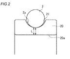
- a perpendicular line L is drawn in the inner ring 10 from the R part-side both ends P1 of the rolling surface 1a of a roller 1, the distance from the inner-ring outside surface 10a to the inner-ring inside surface 10b of the perpendicular line L is measured, and the average value thereof is taken as T.
- Fig. 1A illustrating a case where an effective hard layer is formed on the outside surface 10a of an inner ring 10 in a cylindrical roller bearing
- a perpendicular line L is drawn in the inner ring 10 from the R part-side both ends P1 of the rolling surface 1a of a roller 1
- the distance from the inner-ring outside surface 10a to the inner-ring inside surface 10b of the perpendicular line L is measured, and the average value thereof is taken as T.
- FIG. 1B illustrating a case where an effective hard layer is formed on the outside surface 10a of an inner ring 10 in a tapered roller bearing, a perpendicular line L is drawn in the inner ring 10 from the widthwise both ends P2 coming into contact with the rolling surface 1 a of a roller 1 in the region excluding a clearance groove 11 of the inner-ring outside surface 10a, the distance from the inner-ring outside surface 10a to the inner-ring inside surface 10b of the perpendicular line L is measured, and the average value thereof is taken as T.
- FIG. 1C illustrating a case where an effective hardened layer is formed on the inside surface 12a of an outer ring 12 in a self-aligning roller bearing
- a perpendicular line L is drawn in the outer ring 12 from the R part-side both ends P3 of the rolling surface 1a of a roller 1 in the inside surface 12a of the outer ring 12, the distance from the outer-ring inside surface 12a to the outer-ring outside surface 12b of the perpendicular line L is measured, and the average value thereof is taken as T.
- a heating coil is disposed to face a portion to be hardened, and a high-frequency current is flowed to the heating coil to cause induction heating, as a result, the heated portion is hardened over a certain depth.
- the heating coil is disposed to face the raceway surface of the bearing ring and the fitting surface (opposite-raceway surface) as well as the contact portion with a seal, preferably to face the entire surface of the bearing ring, and the above-described hardened layer is formed by adjusting the output of the heating coil, the treatment time, etc.
- Each of steel materials having alloy compositions shown in Table 1 was prepared, subjected to a spheroidizing annealing treatment, machined to produce a race of a thrust bearing 51305, and then induction heat-treated under the following heating conditions to form a hardened layer on the race surface.
- the DI value was calculated according to formula (1).
- the race surface was electrolytically polished by about 10 ⁇ m, and the polished surface was structurally analyzed by X-ray diffraction method to determine the volume fraction of austenite phase (retained austenite amount). The results are shown in Table 1.
- Comparative Example 1 the carbon amount and the retained austenite amount fell below respective ranges specified in the present invention, and flaking originated from a foreign substance indentation was generated.
- Comparative Example 2 the carbon amount and the retained austenite amount each specified in the present invention were satisfied, but early flaking was generated, and the lifetime was short compared with Comparative Example 1.
- the flaking was observed, internally-originated flaking was generated, and this is considered to be caused because a fracture occurred from the inside due to a lack of quenching property.
- the DI value was determined and found to be 0.9. That is, it is seen from Comparative Example 2 that a quenching property of 1.0 or more in terms of DI value is necessary for suppressing the internally originating-type flaking.
- Examples 1 to 3 the lifetime can be greatly extended.
- the type of flaking was surface originating-type flaking originated from a foreign substance indentation, similarly to Comparative Example 1, it is understood that in a lubricating environment allowing the mixing of a foreign substance, a quenching property high enough to prevent internally originating-type flaking from occurring due to a lack of hardness must be ensured (in terms of DI value, 1.0 or more, preferably 2.1 or more) and the retained austenite amount must be 12 vol% or more.
- the steel material of Example 2 and the steel material of Example 3 correspond to SUJ2 and SUJ3, respectively.
- a steel material obtained by applying a spheroidizing annealing treatment to SUJ2 or SUJ3 was machined to produce an inner ring of a cylindrical roller bearing NU2326 and further subjected, as shown in Table 2, to immersion quenching by furnace heating in Comparative Example 3 or induction heating under the above-described heating conditions in Comparative Example 4 and Examples 4 to 7.
- Comparative Example 4 and Examples 4 to 7 the retained austenite amounts of raceway surface and core part, and the average retained austenite amount were adjusted to those shown in Table 2 by the processing conditions.
- Comparative Example 3 a hardening treatment by standard furnace heating was applied, and the quality may be a standard quality. It is seen that the dimensional change amount is in good correlation with the average retained austenite amount and as long as the average retained austenite amount is 12 vol% or less, even when a large retained austenite amount of 12 vol% or more is ensured in the raceway surface, a dimensional change greater than that of a standard bearing is not caused.
- a steel material obtained by applying a spheroidizing annealing treatment to SUJ2 or SUJ3 was machined to produce an inner ring of a cylindrical roller bearing NU2326 and further subjected, as shown in Table 3, to immersion quenching by furnace heating in Comparative Example 5 or induction heating under the above-described heating conditions in Comparative Example 6 and Examples 8 to 11.
- the hardness of each of the surface and the core part and the residual compressive stress of the raceway surface were adjusted to those shown in Table 3 by the processing conditions.
- the surface hardness indicates a hardness at a position 0.2 mm deep from the surface of the raceway surface, and the core part surface indicates a lowest hardness irrespective of the measurement position.
- the residual compressive stress of the raceway surface was determined by the X-ray diffraction method.
- a cylindrical roller bearing NU2326 was assembled using each of the inner rings and subjected to a lifetime test under the following conditions. The results are shown by a relative value (lifetime ratio) to Comparative Example 5 in Table 3.
- Comparative Example 5 is the same standard bearing as Comparative Example 3.
- the lifetime extending effect is in good correlation with the residual compressive stress, and when a residual compressive stress of -100 MPa or less (a residual stress by compression of 100 MPa or more) is imparted, a lifetime extending effect of 2 times or more relative to Comparative Example 5 is obtained.
- a lifetime extending effect exceeding 3 times is obtained.
- An oil that is likely to cause white structure flaking is used for the lubrication, but white structure flaking occurs generally in a shorter time than the calculated lifetime and therefore, setting the residual compressive stress to -200 MPa or less is thought to be effective also in suppressing the white structure flaking.
- the hardness difference between the surface and the core part needs to be 150 HV or more.
- Comparative Example 7 Thereafter, immersion quenching by furnace heating was performed in Comparative Example 7, Comparative Example 8 and Comparative Example 11.
- heating coils were disposed to face the raceway surface side and the opposite-raceway surface side (inner-ring inside surface), respectively, and the hardening state of the raceway surface and opposite-raceway surface was changed as shown in Table 6 by adjusting the output of each heating coil under the above-described heating conditions.
- a induction heat treatment was applied under the same conditions to the portion except for the raceway surface and opposite-raceway surface to form a hardened layer in all inner rings.
- Example 20 the crushing strength is slightly lower than the case where immersion quenching was performed. This is considered to result because the hardened layer of the opposite-raceway surface is thicker than the hardened layer of the raceway surface (Y 0 ⁇ Y 0 '). In terms of the depth relationship between the hardened layer of the raceway surface and the hardened layer of the opposite-raceway surface, the crushing strength is remarkably enhanced by setting the depth of the hardened layer of the raceway surface to half or less the depth of the hardened layer of the opposite-raceway surface (Y 0 '/Y 0 ⁇ 0.5).
- Comparative Example 9 it is considered that the residual compressive stress necessary for the surface in the raceway surface could not be ensured because the hardened layer of the raceway surface in the inner ring was too thick (Y 0 /T>30%). Furthermore, in Comparative Example 10, the required residual compressive stress could not be obtained because of the excessively thin core part (W/T>55%), and the lifetime was short.
- the rolling bearing of the present invention is suitable as a bearing for use in applications where a high load or an impact load is imposed, such as wind power generator, construction machine and industrial robot.
Landscapes
- Chemical & Material Sciences (AREA)
- Engineering & Computer Science (AREA)
- Mechanical Engineering (AREA)
- Materials Engineering (AREA)
- Metallurgy (AREA)
- Organic Chemistry (AREA)
- General Engineering & Computer Science (AREA)
- Crystallography & Structural Chemistry (AREA)
- Thermal Sciences (AREA)
- Physics & Mathematics (AREA)
- Manufacturing & Machinery (AREA)
- Rolling Contact Bearings (AREA)
- Heat Treatment Of Articles (AREA)
Applications Claiming Priority (6)
| Application Number | Priority Date | Filing Date | Title |
|---|---|---|---|
| JP2012238231A JP2014088893A (ja) | 2012-10-29 | 2012-10-29 | 転がり軸受及びその製造方法 |
| JP2012241823A JP2014092200A (ja) | 2012-11-01 | 2012-11-01 | 転がり軸受 |
| JP2012241822A JP2014092199A (ja) | 2012-11-01 | 2012-11-01 | 転がり軸受 |
| JP2013151873A JP2015021591A (ja) | 2013-07-22 | 2013-07-22 | 転がり軸受 |
| JP2013152358A JP2015021599A (ja) | 2013-07-23 | 2013-07-23 | 転がり軸受 |
| PCT/JP2013/071421 WO2014069068A1 (fr) | 2012-10-29 | 2013-08-07 | Roulement |
Publications (2)
| Publication Number | Publication Date |
|---|---|
| EP2913548A1 true EP2913548A1 (fr) | 2015-09-02 |
| EP2913548A4 EP2913548A4 (fr) | 2015-12-16 |
Family
ID=50626990
Family Applications (1)
| Application Number | Title | Priority Date | Filing Date |
|---|---|---|---|
| EP13852223.0A Withdrawn EP2913548A4 (fr) | 2012-10-29 | 2013-08-07 | Roulement |
Country Status (4)
| Country | Link |
|---|---|
| US (2) | US9249476B2 (fr) |
| EP (1) | EP2913548A4 (fr) |
| CN (1) | CN105121877A (fr) |
| WO (1) | WO2014069068A1 (fr) |
Cited By (1)
| Publication number | Priority date | Publication date | Assignee | Title |
|---|---|---|---|---|
| CN108350945A (zh) * | 2015-10-29 | 2018-07-31 | Ntn株式会社 | 用于生产轴承环的方法和用于生产双列圆锥滚子轴承的方法 |
Families Citing this family (12)
| Publication number | Priority date | Publication date | Assignee | Title |
|---|---|---|---|---|
| WO2018139460A1 (fr) * | 2017-01-25 | 2018-08-02 | Ntn株式会社 | Composant de roulement, palier, et procédé de production d'un composant de roulement |
| JP6817086B2 (ja) * | 2017-01-25 | 2021-01-20 | Ntn株式会社 | 転動部品の製造方法 |
| EP3604840B1 (fr) * | 2017-03-28 | 2022-02-09 | NTN Corporation | Roulement à rouleaux coniques |
| EP3604841B1 (fr) * | 2017-03-28 | 2022-02-16 | NTN Corporation | Roulement à rouleaux coniques |
| JP7550510B2 (ja) * | 2019-09-26 | 2024-09-13 | Ntn株式会社 | 転がり軸受 |
| JP7681942B2 (ja) | 2019-10-01 | 2025-05-23 | Ntn株式会社 | 軸受部品 |
| IT202000007048A1 (it) * | 2020-04-03 | 2021-10-03 | Skf Ab | Unita’ cuscinetto con collare di serraggio concentrico |
| CN115398197B (zh) * | 2020-04-30 | 2025-09-16 | 日本精工株式会社 | 耐压痕性的测定方法、滚动轴承的耐压痕性的预测方法、机械加工条件的选定方法、轴承材料品质的选定方法、抛光加工条件的选定方法以及轴承制造方法 |
| JP7749324B2 (ja) * | 2021-01-13 | 2025-10-06 | Ntn株式会社 | 軸部材 |
| CN113088639B (zh) * | 2021-03-30 | 2023-05-23 | 江西红睿马钢管股份有限公司 | 一种冷碾扩轴承用轴承钢管检验品控方法 |
| DE102021114790A1 (de) | 2021-06-09 | 2022-12-15 | Schaeffler Technologies AG & Co. KG | Axialwälzlager |
| CN117145870A (zh) * | 2023-10-31 | 2023-12-01 | 万向钱潮股份公司 | 一种高性能滚子及制造方法 |
Family Cites Families (14)
| Publication number | Priority date | Publication date | Assignee | Title |
|---|---|---|---|---|
| JPH04208426A (ja) | 1990-11-30 | 1992-07-30 | Olympus Optical Co Ltd | 射出成形品自動取出しロボットおよび射出成形品の取出し方法 |
| JP3422094B2 (ja) * | 1994-10-14 | 2003-06-30 | 日本精工株式会社 | 転がり軸受 |
| JPH10226817A (ja) | 1996-12-11 | 1998-08-25 | Sumitomo Metal Ind Ltd | 軟窒化用鋼材の製造方法及びその鋼材を用いた軟窒化部品 |
| JP4208426B2 (ja) * | 2001-03-01 | 2009-01-14 | Ntn株式会社 | 高周波焼入れ方法および軸受部品 |
| KR100545621B1 (ko) * | 2001-03-07 | 2006-01-24 | 신닛뽄세이테쯔 카부시키카이샤 | 중공 스태빌라이저용 전봉 용접 강관 |
| EP1489318A4 (fr) * | 2002-03-27 | 2008-10-29 | Nsk Ltd | Roulement a billes pour transmission de type non etagee a courroie |
| JP2004011712A (ja) | 2002-06-05 | 2004-01-15 | Nsk Ltd | 転がり軸受、これを用いたベルト式無段変速機 |
| JP4390576B2 (ja) * | 2003-03-04 | 2009-12-24 | 株式会社小松製作所 | 転動部材 |
| JP4390526B2 (ja) * | 2003-03-11 | 2009-12-24 | 株式会社小松製作所 | 転動部材およびその製造方法 |
| US20070194504A1 (en) | 2003-10-08 | 2007-08-23 | Hirokazu Nakashima | Heat Treatment System |
| JP5260032B2 (ja) * | 2007-11-26 | 2013-08-14 | 山陽特殊製鋼株式会社 | 冷間加工性に優れた高周波焼入用鋼、該鋼からなる転動部材および転動部材を用いた直線運動装置 |
| JP2009270172A (ja) * | 2008-05-09 | 2009-11-19 | Nsk Ltd | 転がり軸受用軌道輪の製造方法 |
| JP5895493B2 (ja) | 2011-01-21 | 2016-03-30 | 日本精工株式会社 | 転がり軸受の製造方法、高周波熱処理装置 |
| JP5682590B2 (ja) * | 2012-04-10 | 2015-03-11 | 株式会社ニコン | 撮像装置及び画像表示装置 |
-
2013
- 2013-08-07 US US14/439,016 patent/US9249476B2/en not_active Expired - Fee Related
- 2013-08-07 EP EP13852223.0A patent/EP2913548A4/fr not_active Withdrawn
- 2013-08-07 WO PCT/JP2013/071421 patent/WO2014069068A1/fr not_active Ceased
- 2013-08-07 CN CN201380056354.1A patent/CN105121877A/zh active Pending
-
2015
- 2015-12-22 US US14/978,528 patent/US9394583B2/en not_active Expired - Fee Related
Cited By (2)
| Publication number | Priority date | Publication date | Assignee | Title |
|---|---|---|---|---|
| CN108350945A (zh) * | 2015-10-29 | 2018-07-31 | Ntn株式会社 | 用于生产轴承环的方法和用于生产双列圆锥滚子轴承的方法 |
| EP3369954A4 (fr) * | 2015-10-29 | 2019-04-03 | NTN Corporation | Procédé de fabrication d'une bague de roulement et procédé de fabrication d'un roulement à rouleaux coniques à rangées multiples |
Also Published As
| Publication number | Publication date |
|---|---|
| CN105121877A (zh) | 2015-12-02 |
| US9249476B2 (en) | 2016-02-02 |
| US20160108491A1 (en) | 2016-04-21 |
| US20150259764A1 (en) | 2015-09-17 |
| EP2913548A4 (fr) | 2015-12-16 |
| WO2014069068A1 (fr) | 2014-05-08 |
| US9394583B2 (en) | 2016-07-19 |
Similar Documents
| Publication | Publication Date | Title |
|---|---|---|
| US9394583B2 (en) | Rolling bearing | |
| KR101355666B1 (ko) | 연질화 고주파 켄칭용 기계 구조용 강 및 기계 구조용 강 부품과 그 제조 방법 | |
| EP2386669B1 (fr) | Élément constitutif de roulement, procédé pour sa production, et roulement à billes et à rouleaux comportant l'élément constitutif | |
| EP1710458B1 (fr) | Procede de traitement thermique de l'acier | |
| US5626974A (en) | Rolling bearing for use under high temperature conditions | |
| JP5895493B2 (ja) | 転がり軸受の製造方法、高周波熱処理装置 | |
| CN103237913B (zh) | 滚动轴承及其制造方法 | |
| EP2716784A1 (fr) | Organe de roulement coulissant, son procédé de fabrication et palier à roulement | |
| KR20150036049A (ko) | 롤링 베어링 요소, 특히 롤링 베어링 링 | |
| US5853249A (en) | Rolling contact bearing | |
| EP3009698A1 (fr) | Roulement à rouleaux coniques | |
| JP2014020538A (ja) | 転がり軸受、転がり軸受の製造方法、高周波熱処理装置 | |
| JP2002180203A (ja) | 針状ころ軸受構成部品およびその製造方法 | |
| JP5298683B2 (ja) | 転がり軸受及びその製造方法 | |
| KR20240012362A (ko) | 궤도륜 및 샤프트 | |
| JP2012237338A (ja) | 転がり軸受 | |
| TWI575170B (zh) | Ball screw device | |
| JP2007113027A (ja) | 鋼の熱処理方法、転がり支持装置の製造方法、転がり支持装置 | |
| EP4394058A1 (fr) | Roulement à rouleaux | |
| JPH06117438A (ja) | 浸炭処理鋼による転がり軸受 | |
| JP4900098B2 (ja) | 転がり軸受 | |
| KR20120120000A (ko) | 롤링 슬라이드 이동 부재 및 그 제조 방법 및 롤링 베어링 | |
| JP2006299313A (ja) | 転がり支持装置 | |
| JP2015021591A (ja) | 転がり軸受 | |
| JP2009019713A (ja) | 転がり軸受 |
Legal Events
| Date | Code | Title | Description |
|---|---|---|---|
| PUAI | Public reference made under article 153(3) epc to a published international application that has entered the european phase |
Free format text: ORIGINAL CODE: 0009012 |
|
| 17P | Request for examination filed |
Effective date: 20150428 |
|
| AK | Designated contracting states |
Kind code of ref document: A1 Designated state(s): AL AT BE BG CH CY CZ DE DK EE ES FI FR GB GR HR HU IE IS IT LI LT LU LV MC MK MT NL NO PL PT RO RS SE SI SK SM TR |
|
| AX | Request for extension of the european patent |
Extension state: BA ME |
|
| RA4 | Supplementary search report drawn up and despatched (corrected) |
Effective date: 20151113 |
|
| RIC1 | Information provided on ipc code assigned before grant |
Ipc: C21D 9/40 20060101ALI20151109BHEP Ipc: C22C 38/00 20060101ALI20151109BHEP Ipc: F16C 19/02 20060101ALI20151109BHEP Ipc: F16C 33/62 20060101ALI20151109BHEP Ipc: C21D 1/09 20060101ALN20151109BHEP Ipc: F16C 33/64 20060101AFI20151109BHEP Ipc: F16C 33/34 20060101ALI20151109BHEP Ipc: C22C 38/02 20060101ALI20151109BHEP Ipc: F16C 19/38 20060101ALN20151109BHEP Ipc: C22C 38/04 20060101ALI20151109BHEP Ipc: F16C 19/36 20060101ALN20151109BHEP Ipc: F16C 33/58 20060101ALN20151109BHEP Ipc: F16C 19/22 20060101ALI20151109BHEP Ipc: F16C 19/26 20060101ALN20151109BHEP Ipc: C22C 38/44 20060101ALI20151109BHEP Ipc: F16C 33/32 20060101ALI20151109BHEP |
|
| DAX | Request for extension of the european patent (deleted) | ||
| STAA | Information on the status of an ep patent application or granted ep patent |
Free format text: STATUS: THE APPLICATION HAS BEEN WITHDRAWN |
|
| 18W | Application withdrawn |
Effective date: 20160531 |