EP2913562B1 - Dispositif de changement de vitesse placé au volant de direction d'un véhicule - Google Patents
Dispositif de changement de vitesse placé au volant de direction d'un véhicule Download PDFInfo
- Publication number
- EP2913562B1 EP2913562B1 EP15000168.3A EP15000168A EP2913562B1 EP 2913562 B1 EP2913562 B1 EP 2913562B1 EP 15000168 A EP15000168 A EP 15000168A EP 2913562 B1 EP2913562 B1 EP 2913562B1
- Authority
- EP
- European Patent Office
- Prior art keywords
- shift
- steering wheel
- rocker
- contact part
- housing
- Prior art date
- Legal status (The legal status is an assumption and is not a legal conclusion. Google has not performed a legal analysis and makes no representation as to the accuracy of the status listed.)
- Active
Links
Images
Classifications
-
- F—MECHANICAL ENGINEERING; LIGHTING; HEATING; WEAPONS; BLASTING
- F16—ENGINEERING ELEMENTS AND UNITS; GENERAL MEASURES FOR PRODUCING AND MAINTAINING EFFECTIVE FUNCTIONING OF MACHINES OR INSTALLATIONS; THERMAL INSULATION IN GENERAL
- F16H—GEARING
- F16H59/00—Control inputs to control units of change-speed- or reversing-gearings for conveying rotary motion
- F16H59/02—Selector apparatus
-
- B—PERFORMING OPERATIONS; TRANSPORTING
- B60—VEHICLES IN GENERAL
- B60K—ARRANGEMENT OR MOUNTING OF PROPULSION UNITS OR OF TRANSMISSIONS IN VEHICLES; ARRANGEMENT OR MOUNTING OF PLURAL DIVERSE PRIME-MOVERS IN VEHICLES; AUXILIARY DRIVES FOR VEHICLES; INSTRUMENTATION OR DASHBOARDS FOR VEHICLES; ARRANGEMENTS IN CONNECTION WITH COOLING, AIR INTAKE, GAS EXHAUST OR FUEL SUPPLY OF PROPULSION UNITS IN VEHICLES
- B60K20/00—Arrangement or mounting of change-speed gearing control devices in vehicles
- B60K20/02—Arrangement or mounting of change-speed gearing control devices in vehicles of initiating means
- B60K20/06—Arrangement or mounting of change-speed gearing control devices in vehicles of initiating means mounted on steering column or the like
-
- H—ELECTRICITY
- H01—ELECTRIC ELEMENTS
- H01H—ELECTRIC SWITCHES; RELAYS; SELECTORS; EMERGENCY PROTECTIVE DEVICES
- H01H21/00—Switches operated by an operating part in the form of a pivotable member acted upon directly by a solid body, e.g. by a hand
- H01H21/02—Details
- H01H21/18—Movable parts; Contacts mounted thereon
- H01H21/36—Driving mechanisms
-
- F—MECHANICAL ENGINEERING; LIGHTING; HEATING; WEAPONS; BLASTING
- F16—ENGINEERING ELEMENTS AND UNITS; GENERAL MEASURES FOR PRODUCING AND MAINTAINING EFFECTIVE FUNCTIONING OF MACHINES OR INSTALLATIONS; THERMAL INSULATION IN GENERAL
- F16H—GEARING
- F16H59/00—Control inputs to control units of change-speed- or reversing-gearings for conveying rotary motion
- F16H59/02—Selector apparatus
- F16H2059/0239—Up- and down-shift or range or mode selection by repeated movement
- F16H2059/0247—Up- and down-shift or range or mode selection by repeated movement with lever or paddle behind steering wheel
Definitions
- the invention relates to a steering wheel switching device for triggering switching operations in a vehicle according to the preamble of patent claim 1.
- Such steering wheel switching devices are known from the prior art, which are usually designed as a steering wheel rockers and work on the basis of micro-switches or safety mats. Such steering wheel switching devices have problems insofar as the switching paths realized in connection with them, i. the signal switching circuits are limited.
- the DE 10 2012 014 019 A shows a steering wheel switching device, which serves to trigger switching operations in a motor vehicle.
- this known steering wheel switching device includes an electrical switching element or a steering wheel fixed contact part, which cooperates with a movable contact part.
- the movable contact part between its spaced from the steering wheel fixed contact part rest position and its voltage applied to the steering wheel fixed contact part switching position is adjustable.
- a shift lever or shift paddle is actuated.
- the movable contact part is arranged on a rocker switch, wherein the rocker switch by means of the shift lever or shift paddle from its initial position in which it assumes its rest position with the movable contact part, is adjustable in its operating position in which the movable contact part assumes its switching position.
- the present invention seeks to provide a steering gear switching device for triggering switching operations in a vehicle available, in which a permanently reliable and safe operation is guaranteed and the mechanical load on the contact parts largely independent of the force is, with which the steering wheel switching device is actuated.
- the design of the movable contact part as a contact spring ensures that force exerted on the actuation of the steering wheel switching device can be divided into a force component which serves to establish and maintain the contact between the contact parts and a force component resulting from the deformation of the contact spring can be buffered.
- the device's internal switching paths are significantly reduced, without affecting the reliability of the steering wheel switching device in any form, for example, from about 2 mm to 0.6 mm.
- the actual device internal switching path is translated by means of the rocker switch on the actual Heidelbergpaddle or its Betjansweg.
- the steering wheel switching device has a housing in which the rocker is pivotally mounted about a rocker axis and the Wegpaddle about a Wegwippenachse spaced and parallel Heidelbergpaddleachse, it is possible with a relatively small technical and design effort, a wide range of the ratio between the device-internal switching path and to provide the actuating travel of the Wegpaddle. In addition, this compact design of the steering wheel switching device according to the invention can be realized.
- the housing and steering wheel fixed contact part between the shift paddle axis and the Wegpaddleachse is arranged, whereby the compactness of the steering wheel switching device according to the invention is further promoted.
- the steering wheel switching device has a compression spring, which between the housing and the rocker is arranged and biased by means of the rocker switch in the direction of its initial position.
- the rocker has a spring sleeve which protrudes with its free end of the rocker and is in contact with a shift gate , By means of which it is compressible during the movement of the rocker switch from the output in its operating position.
- the force-displacement curve can be adjusted so that an increase in force takes place in a very short path, which then breaks down abruptly also very short way, e.g. to about 30 to 50% of the maximum force.
- the adjustment of the force-displacement curve as well as the electrical switching point may be due to the geometry of the shift gate as well the ratio between the pivotal movement of the shift paddle and the pivotal movement of the rocker switch are more or less arbitrarily designed.
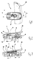
- a steering wheel switching device 1 serves to trigger switching operations in a vehicle, the release should be easily possible by the driver, without the possibilities of the driver, his attention be devoted to the operation of the vehicle and the traffic.
- the steering wheel switching device 1 is arranged on the steering wheel of the vehicle, not shown in the figures.
- To the steering wheel switching device 1 includes a housing 2, which is suitably mounted on the steering wheel of the vehicle.
- a steering wheel fixed contact part of a steering wheel fixed contact part in addition to the steering wheel movable contact part 4 having trigger connection 3, 4 is arranged.
- the movable in relation to the steering wheel or with respect to the housing 2 contact part 4 is formed in the form of a contact spring 4.
- the contact spring 4 has a contact portion 5, with which it can be brought into contact with the steering wheel fixed contact part 3, and a mounting portion 6, to which it is attached to a pivotally mounted within the housing 2 about a shift paddle 7 rocker switch 8.
- the mounting portion 6 of the contact spring 4 in the illustrated embodiment, the material of the switching rocker 8 is encapsulated.
- the rocker switch 8 with the attached contact spring 4 is within the housing 2 from an initial position in which the contact portion 5 of the contact spring 4 has a distance from the steering wheel fixed contact part 3, adjustable in an operating position in which the contact portion 5 of the contact spring 4 is in System is located on the steering wheel fixed contact part 3 and thus the trip connection 3, 4 closes and triggers a switching operation.
- a compression spring 10 is arranged with a comparatively small distance to the rocker shaft 7, by means of the rocker switch 8 in the direction of its initial position, in between the contact portion 5 of the contact spring 4 and the steering wheel fixed contact part 3 is a distance, biased.
- a rubber buffer 11 is provided on the inside of the lower wall 9, by means of which the movement of the rocker switch 8 is limited beyond its operating position.
- the steering wheel switching device 1 is in a portion of the housing 2, which is approximately opposite the shift pad axis receiving portion 7, a Wegpaddleachse 12, around which a Heidelbergpaddle 13 is pivotable.
- the pivoting of the Wegpaddle 13 is performed manually.
- a gap is provided between the shift paddle axis 7 and the Heidelbergpaddleachse 12, which are parallel to each other. In this space are the steering wheel fixed contact part and an essential section the rocker switch 8 with the contact portion 5 of the contact spring. 4
- the rocker switch 8 is pivoted due to the contact between the underside of the Wegpaddle 13 and the top of the rocker switch 8 in the counterclockwise direction about the rocker axis 7. In this pivotal movement in the counterclockwise direction, the rocker switch 8 from its initial position into its operating position and according to the contact spring 4 from its rest in its switching position, in which the contact portion 5 of the contact spring 4 in contact with the steering wheel fixed contact part 3.
- the contact spring 4 Due to the quasi freely configurable leverage ratios between the Heidelbergpaddle 13 and the Heidelbergpaddleachse 12 and the rocker switch 8 and the rocker axis 7 and the switch rocker 8 arbitrarily selectable arrangement of the contact spring 4 can be present in the starting position of the rocker switch 8 distance between the contact portion of the contact spring 4th on the one hand and the steering wheel fixed contact part 3 be very small, for example, be in the order of 0.6 mm, without a safe functioning and high reliability of the steering gear switching device according to the invention would be impaired. Nevertheless, the pivotal movement of the shift paddle can be compared to the distance between the contact portion 5 of the contact spring 4 and steering wheel fixed contact part be large.
- a spring sleeve 14 is arranged in the illustrated rocker 8 in the illustrated embodiment.
- the spring sleeve 14 cooperates with a fixed in the housing 2 shift gate 15.
- the spring sleeve 14 protrudes with its not recorded in the rocker switch 8 free end 16 of the rocker switch 8 and is located with this free end 16 against the shift gate 15 at.
- the spring sleeve 14 When swinging the Wennpaddle 13 and the rocker switch 8 from the output in their operating position, the spring sleeve 14 must be further compressed with increasing distance. Accordingly, the spring sleeve 14 and the shift gate 15 can be configured or arranged so that virtually any force-displacement curves for the pivotal movement of the Wegpaddle 13 and the rocker switch 8 can be created.
Landscapes
- Engineering & Computer Science (AREA)
- Mechanical Engineering (AREA)
- General Engineering & Computer Science (AREA)
- Chemical & Material Sciences (AREA)
- Combustion & Propulsion (AREA)
- Transportation (AREA)
- Steering Controls (AREA)
Claims (6)
- Dispositif de commande de vitesse au volant pour déclencher des changements de vitesse dans un véhicule, avec une partie de contact solidaire du volant (3), une partie de contact mobile (4) pouvant être déplacée entre sa position de repos espacée par rapport à la partie de contact solidaire du volant (3) et sa position de changement de vitesse en appui contre la partie de contact solidaire du volant (3), une palette de commande de vitesse (13) au moyen de laquelle la partie de contact mobile (3) peut être déplacée de sa position de repos vers sa position de changement de vitesse, et une bascule de commande de vitesse (8) sur laquelle la partie de contact mobile (4) est disposée et qui peut être déplacée par la palette de commande de vitesse (13) de sa position initiale dans laquelle la partie de contact mobile (4) adopte sa position de repos vers sa position de fonctionnement dans laquelle la partie de contact mobile (4) adopte sa position de changement de vitesse,
caractérisé en ce que la partie de contact mobile (4) disposée sur la bascule de commande de vitesse (8) est réalisée en tant que ressort de contact (4) qui présente un segment de contact (5) pouvant être mis en appui contre la partie de contact solidaire du volant (3) et un segment de fixation (6) relié à la bascule de commande de vitesse (8), de préférence surmoulé par le matériau de la bascule de commande de vitesse (8). - Dispositif de commande de vitesse au volant selon la revendication 1, avec un boîtier (2) dans lequel la bascule de commande de vitesse (8) est montée de manière pivotante autour d'un axe de bascule de commande de vitesse (7), et la palette de commande de vitesse (13) étant montée de manière pivotante autour d'un axe de palette de commande de vitesse (12) espacé par rapport à l'axe de bascule de commande de vitesse (7) et parallèle à celui-ci.
- Dispositif de commande de vitesse au volant selon la revendication 2, dans lequel la partie de contact solidaire du boîtier et du volant (3) est disposée entre l'axe de la bascule de commande de vitesse (7) et l'axe de la palette de commande de vitesse (12).
- Dispositif de commande de vitesse au volant selon la revendication 2 ou 3, avec un ressort de pression (10) disposé entre le boîtier (2) et la bascule de commande de vitesse (8) et précontraint en direction de sa position initiale au moyen de la bascule de commande de vitesse (8).
- Dispositif de commande de vitesse au volant selon l'une des revendications 2 à 4, avec un tampon en caoutchouc (11) disposé entre la bascule de commande de vitesse (8) et le boîtier (2) et au moyen duquel un déplacement de la bascule de commande de vitesse (8) au-delà de la position de fonctionnement de celle-ci peut être limité.
- Dispositif de commande de vitesse au volant selon l'une des revendications 1 à 5, dont la bascule de commande de vitesse (8) présente une douille élastique (14) qui dépasse avec son extrémité libre (16) à partir de la bascule de commande de vitesse (8) et est en appui contre une coulisse de commande de vitesse (15) au moyen de laquelle elle peut être comprimée lors du déplacement de la bascule de commande de vitesse (8) de la position initiale de celle-ci vers la position de fonctionnement de celle-ci.
Applications Claiming Priority (1)
| Application Number | Priority Date | Filing Date | Title |
|---|---|---|---|
| DE102014002398.2A DE102014002398A1 (de) | 2014-02-24 | 2014-02-24 | Lenkradschaltvorrichtung zur Auslösung von Schaltvorgängen in einem Fahrzeug |
Publications (2)
| Publication Number | Publication Date |
|---|---|
| EP2913562A1 EP2913562A1 (fr) | 2015-09-02 |
| EP2913562B1 true EP2913562B1 (fr) | 2017-04-12 |
Family
ID=52394885
Family Applications (1)
| Application Number | Title | Priority Date | Filing Date |
|---|---|---|---|
| EP15000168.3A Active EP2913562B1 (fr) | 2014-02-24 | 2015-01-21 | Dispositif de changement de vitesse placé au volant de direction d'un véhicule |
Country Status (2)
| Country | Link |
|---|---|
| EP (1) | EP2913562B1 (fr) |
| DE (1) | DE102014002398A1 (fr) |
Cited By (2)
| Publication number | Priority date | Publication date | Assignee | Title |
|---|---|---|---|---|
| KR20200002375U (ko) * | 2019-04-19 | 2020-10-28 | 주식회사 모베이스전자 | 자동차의 변속 스위치 장치 |
| CN113771617A (zh) * | 2021-09-26 | 2021-12-10 | 宁波昌晖汽车零部件有限公司 | 用于方向盘的换挡拨片 |
Family Cites Families (11)
| Publication number | Priority date | Publication date | Assignee | Title |
|---|---|---|---|---|
| DE621281C (de) * | 1932-12-16 | 1935-11-04 | Siemens Schuckertwerke Akt Ges | Installationskippschalter mit vermindertem Schaltgeraeusch |
| DE2402613C3 (de) * | 1974-01-21 | 1979-10-25 | Gebr. Vedder Gmbh, 5885 Schalksmuehle | Tastschalter |
| DE3421021A1 (de) * | 1984-06-06 | 1985-12-12 | Fa. Albrecht Jung, 5885 Schalksmühle | Stoessellagerung eines elektrischen tastschalters |
| DE3606508A1 (de) * | 1986-02-28 | 1987-09-03 | Jung Albrecht Fa | Schaltmechanismus fuer ein elektrisches installationsgeraet |
| JP2525658Y2 (ja) * | 1991-09-18 | 1997-02-12 | アルプス電気株式会社 | シーソ型スイッチ |
| DE4439008C2 (de) * | 1994-11-02 | 1999-05-27 | Eaton Controls Gmbh | Elektrischer Tastschalter |
| US5833048A (en) * | 1995-02-07 | 1998-11-10 | Eaton Corporation | Rocker switch especially for vehicles |
| DE10140164A1 (de) * | 2001-08-22 | 2003-03-13 | Zf Lemfoerder Metallwaren Ag | Steuereinheit für die Gang- oder Schaltprogrammwahl eines automatischen Kraftfahrzeuggetriebes |
| US6979788B1 (en) * | 2004-08-26 | 2005-12-27 | Texas Instruments Incorporated | Electrical switch system responsive to gear selection of vehicular transmission |
| US9082568B2 (en) * | 2010-07-19 | 2015-07-14 | Trw Automotive Electronics & Components Gmbh | Switch, in particular for an electric parking brake |
| DE102012014019A1 (de) * | 2011-07-21 | 2013-01-24 | Marquardt Gmbh | Elektrischer Schalter |
-
2014
- 2014-02-24 DE DE102014002398.2A patent/DE102014002398A1/de not_active Withdrawn
-
2015
- 2015-01-21 EP EP15000168.3A patent/EP2913562B1/fr active Active
Cited By (4)
| Publication number | Priority date | Publication date | Assignee | Title |
|---|---|---|---|---|
| KR20200002375U (ko) * | 2019-04-19 | 2020-10-28 | 주식회사 모베이스전자 | 자동차의 변속 스위치 장치 |
| KR200492553Y1 (ko) | 2019-04-19 | 2020-11-04 | 주식회사 모베이스전자 | 자동차의 변속 스위치 장치 |
| CN113771617A (zh) * | 2021-09-26 | 2021-12-10 | 宁波昌晖汽车零部件有限公司 | 用于方向盘的换挡拨片 |
| CN113771617B (zh) * | 2021-09-26 | 2023-02-14 | 宁波昌晖汽车零部件有限公司 | 用于方向盘的换挡拨片 |
Also Published As
| Publication number | Publication date |
|---|---|
| EP2913562A1 (fr) | 2015-09-02 |
| DE102014002398A1 (de) | 2015-08-27 |
Similar Documents
| Publication | Publication Date | Title |
|---|---|---|
| DE2360168A1 (de) | Schalter, insbesondere taster | |
| DE102017117509A1 (de) | Elektrisches Gerät | |
| EP2913562B1 (fr) | Dispositif de changement de vitesse placé au volant de direction d'un véhicule | |
| DE10241048A1 (de) | Schalteinrichtung für eine Fahrzeughupe | |
| DE2228096C3 (de) | Elektrischer, mechanisch betätigter Sprungschalter | |
| DE60128356T2 (de) | Mechanische rücksetzvorrichtung für schalter | |
| DE2101197B2 (de) | Elektrischer schnappschalter | |
| DE3532574A1 (de) | Elektrischer schalter mit betaetigungsschieber | |
| EP3002767B1 (fr) | Systeme de contact pour un appareil de commutation electromecanique | |
| DE3936610C2 (de) | Einrichtung zum sprunghaften Einschalten beweglich gelagerter Kontakthebel, insbesondere für einen zweipoligen Fehlerstromschutzschalter | |
| DE452235C (de) | Druckknopfschalter mit Umstellung eines Schalthebels durch eine im Druckknopf angeordnete bewegliche Zunge | |
| EP1887598B1 (fr) | Dispositif de commutation à bascule | |
| DE102008051228B4 (de) | Wippschalter und Auswertevorrichtung mit einem Wippschalter | |
| DE7238173U (de) | Trägheitsunterbrecher | |
| DE2952298C2 (de) | Elektrischer Schalter, insbesondere Lenkstockschalter für Kraftfahrzeuge | |
| DE19906036C1 (de) | Schalter, insbesondere Kfz-Bremslichtschalter | |
| DE1127433B (de) | Elektrischer Kippschalter | |
| DE102004026243B3 (de) | Betätigungseinrichtung zum Schalten | |
| DE1152462B (de) | Anbaufaehiges Vorsatzgeraet fuer elektrische Drucktaster | |
| DE2319141C3 (de) | Mikro-Druckknopfschalter | |
| DE3008756A1 (de) | Verriegelungsvorrichtung fuer eine haushaltsmaschine o.dgl. | |
| DE19904623C2 (de) | Schalter, vorzugsweise Relais | |
| DE3335732A1 (de) | Einrichtung zur rueckstellung des kontakttraegers eines elektromagnetischen schaltgeraetes, insbesondere eines schuetzes | |
| DE4238828C2 (de) | Bremsventil für druckmittelbetätigbare Bremsanlagen von Kraftfahrzeugen, insbesonere Nutzfahrzeugen | |
| DE602004007055T2 (de) | Lenkradschalter |
Legal Events
| Date | Code | Title | Description |
|---|---|---|---|
| PUAI | Public reference made under article 153(3) epc to a published international application that has entered the european phase |
Free format text: ORIGINAL CODE: 0009012 |
|
| AK | Designated contracting states |
Kind code of ref document: A1 Designated state(s): AL AT BE BG CH CY CZ DE DK EE ES FI FR GB GR HR HU IE IS IT LI LT LU LV MC MK MT NL NO PL PT RO RS SE SI SK SM TR |
|
| AX | Request for extension of the european patent |
Extension state: BA ME |
|
| 17P | Request for examination filed |
Effective date: 20160203 |
|
| RBV | Designated contracting states (corrected) |
Designated state(s): AL AT BE BG CH CY CZ DE DK EE ES FI FR GB GR HR HU IE IS IT LI LT LU LV MC MK MT NL NO PL PT RO RS SE SI SK SM TR |
|
| 17Q | First examination report despatched |
Effective date: 20160701 |
|
| GRAP | Despatch of communication of intention to grant a patent |
Free format text: ORIGINAL CODE: EPIDOSNIGR1 |
|
| RIC1 | Information provided on ipc code assigned before grant |
Ipc: B60K 20/06 20060101ALI20161103BHEP Ipc: F16H 59/02 20060101AFI20161103BHEP Ipc: H01H 21/36 20060101ALI20161103BHEP |
|
| INTG | Intention to grant announced |
Effective date: 20161118 |
|
| GRAS | Grant fee paid |
Free format text: ORIGINAL CODE: EPIDOSNIGR3 |
|
| GRAA | (expected) grant |
Free format text: ORIGINAL CODE: 0009210 |
|
| AK | Designated contracting states |
Kind code of ref document: B1 Designated state(s): AL AT BE BG CH CY CZ DE DK EE ES FI FR GB GR HR HU IE IS IT LI LT LU LV MC MK MT NL NO PL PT RO RS SE SI SK SM TR |
|
| REG | Reference to a national code |
Ref country code: GB Ref legal event code: FG4D Free format text: NOT ENGLISH |
|
| REG | Reference to a national code |
Ref country code: CH Ref legal event code: EP |
|
| REG | Reference to a national code |
Ref country code: IE Ref legal event code: FG4D Free format text: LANGUAGE OF EP DOCUMENT: GERMAN |
|
| REG | Reference to a national code |
Ref country code: AT Ref legal event code: REF Ref document number: 884245 Country of ref document: AT Kind code of ref document: T Effective date: 20170515 |
|
| REG | Reference to a national code |
Ref country code: DE Ref legal event code: R096 Ref document number: 502015000819 Country of ref document: DE |
|
| REG | Reference to a national code |
Ref country code: NL Ref legal event code: MP Effective date: 20170412 |
|
| REG | Reference to a national code |
Ref country code: LT Ref legal event code: MG4D |
|
| PG25 | Lapsed in a contracting state [announced via postgrant information from national office to epo] |
Ref country code: NL Free format text: LAPSE BECAUSE OF FAILURE TO SUBMIT A TRANSLATION OF THE DESCRIPTION OR TO PAY THE FEE WITHIN THE PRESCRIBED TIME-LIMIT Effective date: 20170412 |
|
| PG25 | Lapsed in a contracting state [announced via postgrant information from national office to epo] |
Ref country code: FI Free format text: LAPSE BECAUSE OF FAILURE TO SUBMIT A TRANSLATION OF THE DESCRIPTION OR TO PAY THE FEE WITHIN THE PRESCRIBED TIME-LIMIT Effective date: 20170412 Ref country code: HR Free format text: LAPSE BECAUSE OF FAILURE TO SUBMIT A TRANSLATION OF THE DESCRIPTION OR TO PAY THE FEE WITHIN THE PRESCRIBED TIME-LIMIT Effective date: 20170412 Ref country code: LT Free format text: LAPSE BECAUSE OF FAILURE TO SUBMIT A TRANSLATION OF THE DESCRIPTION OR TO PAY THE FEE WITHIN THE PRESCRIBED TIME-LIMIT Effective date: 20170412 Ref country code: NO Free format text: LAPSE BECAUSE OF FAILURE TO SUBMIT A TRANSLATION OF THE DESCRIPTION OR TO PAY THE FEE WITHIN THE PRESCRIBED TIME-LIMIT Effective date: 20170712 Ref country code: GR Free format text: LAPSE BECAUSE OF FAILURE TO SUBMIT A TRANSLATION OF THE DESCRIPTION OR TO PAY THE FEE WITHIN THE PRESCRIBED TIME-LIMIT Effective date: 20170713 Ref country code: ES Free format text: LAPSE BECAUSE OF FAILURE TO SUBMIT A TRANSLATION OF THE DESCRIPTION OR TO PAY THE FEE WITHIN THE PRESCRIBED TIME-LIMIT Effective date: 20170412 |
|
| PG25 | Lapsed in a contracting state [announced via postgrant information from national office to epo] |
Ref country code: SE Free format text: LAPSE BECAUSE OF FAILURE TO SUBMIT A TRANSLATION OF THE DESCRIPTION OR TO PAY THE FEE WITHIN THE PRESCRIBED TIME-LIMIT Effective date: 20170412 Ref country code: IS Free format text: LAPSE BECAUSE OF FAILURE TO SUBMIT A TRANSLATION OF THE DESCRIPTION OR TO PAY THE FEE WITHIN THE PRESCRIBED TIME-LIMIT Effective date: 20170812 Ref country code: LV Free format text: LAPSE BECAUSE OF FAILURE TO SUBMIT A TRANSLATION OF THE DESCRIPTION OR TO PAY THE FEE WITHIN THE PRESCRIBED TIME-LIMIT Effective date: 20170412 Ref country code: PL Free format text: LAPSE BECAUSE OF FAILURE TO SUBMIT A TRANSLATION OF THE DESCRIPTION OR TO PAY THE FEE WITHIN THE PRESCRIBED TIME-LIMIT Effective date: 20170412 Ref country code: RS Free format text: LAPSE BECAUSE OF FAILURE TO SUBMIT A TRANSLATION OF THE DESCRIPTION OR TO PAY THE FEE WITHIN THE PRESCRIBED TIME-LIMIT Effective date: 20170412 Ref country code: BG Free format text: LAPSE BECAUSE OF FAILURE TO SUBMIT A TRANSLATION OF THE DESCRIPTION OR TO PAY THE FEE WITHIN THE PRESCRIBED TIME-LIMIT Effective date: 20170712 |
|
| REG | Reference to a national code |
Ref country code: DE Ref legal event code: R097 Ref document number: 502015000819 Country of ref document: DE |
|
| PG25 | Lapsed in a contracting state [announced via postgrant information from national office to epo] |
Ref country code: DK Free format text: LAPSE BECAUSE OF FAILURE TO SUBMIT A TRANSLATION OF THE DESCRIPTION OR TO PAY THE FEE WITHIN THE PRESCRIBED TIME-LIMIT Effective date: 20170412 Ref country code: SK Free format text: LAPSE BECAUSE OF FAILURE TO SUBMIT A TRANSLATION OF THE DESCRIPTION OR TO PAY THE FEE WITHIN THE PRESCRIBED TIME-LIMIT Effective date: 20170412 Ref country code: EE Free format text: LAPSE BECAUSE OF FAILURE TO SUBMIT A TRANSLATION OF THE DESCRIPTION OR TO PAY THE FEE WITHIN THE PRESCRIBED TIME-LIMIT Effective date: 20170412 Ref country code: RO Free format text: LAPSE BECAUSE OF FAILURE TO SUBMIT A TRANSLATION OF THE DESCRIPTION OR TO PAY THE FEE WITHIN THE PRESCRIBED TIME-LIMIT Effective date: 20170412 Ref country code: CZ Free format text: LAPSE BECAUSE OF FAILURE TO SUBMIT A TRANSLATION OF THE DESCRIPTION OR TO PAY THE FEE WITHIN THE PRESCRIBED TIME-LIMIT Effective date: 20170412 |
|
| PLBE | No opposition filed within time limit |
Free format text: ORIGINAL CODE: 0009261 |
|
| STAA | Information on the status of an ep patent application or granted ep patent |
Free format text: STATUS: NO OPPOSITION FILED WITHIN TIME LIMIT |
|
| PG25 | Lapsed in a contracting state [announced via postgrant information from national office to epo] |
Ref country code: IT Free format text: LAPSE BECAUSE OF FAILURE TO SUBMIT A TRANSLATION OF THE DESCRIPTION OR TO PAY THE FEE WITHIN THE PRESCRIBED TIME-LIMIT Effective date: 20170412 Ref country code: SM Free format text: LAPSE BECAUSE OF FAILURE TO SUBMIT A TRANSLATION OF THE DESCRIPTION OR TO PAY THE FEE WITHIN THE PRESCRIBED TIME-LIMIT Effective date: 20170412 |
|
| 26N | No opposition filed |
Effective date: 20180115 |
|
| PG25 | Lapsed in a contracting state [announced via postgrant information from national office to epo] |
Ref country code: SI Free format text: LAPSE BECAUSE OF FAILURE TO SUBMIT A TRANSLATION OF THE DESCRIPTION OR TO PAY THE FEE WITHIN THE PRESCRIBED TIME-LIMIT Effective date: 20170412 |
|
| REG | Reference to a national code |
Ref country code: CH Ref legal event code: PL |
|
| PG25 | Lapsed in a contracting state [announced via postgrant information from national office to epo] |
Ref country code: MT Free format text: LAPSE BECAUSE OF FAILURE TO SUBMIT A TRANSLATION OF THE DESCRIPTION OR TO PAY THE FEE WITHIN THE PRESCRIBED TIME-LIMIT Effective date: 20170412 |
|
| PG25 | Lapsed in a contracting state [announced via postgrant information from national office to epo] |
Ref country code: FR Free format text: LAPSE BECAUSE OF NON-PAYMENT OF DUE FEES Effective date: 20180131 Ref country code: LU Free format text: LAPSE BECAUSE OF NON-PAYMENT OF DUE FEES Effective date: 20180121 |
|
| REG | Reference to a national code |
Ref country code: IE Ref legal event code: MM4A |
|
| REG | Reference to a national code |
Ref country code: FR Ref legal event code: ST Effective date: 20180928 |
|
| REG | Reference to a national code |
Ref country code: BE Ref legal event code: MM Effective date: 20180131 |
|
| PG25 | Lapsed in a contracting state [announced via postgrant information from national office to epo] |
Ref country code: LI Free format text: LAPSE BECAUSE OF NON-PAYMENT OF DUE FEES Effective date: 20180131 Ref country code: CH Free format text: LAPSE BECAUSE OF NON-PAYMENT OF DUE FEES Effective date: 20180131 Ref country code: BE Free format text: LAPSE BECAUSE OF NON-PAYMENT OF DUE FEES Effective date: 20180131 |
|
| PG25 | Lapsed in a contracting state [announced via postgrant information from national office to epo] |
Ref country code: IE Free format text: LAPSE BECAUSE OF NON-PAYMENT OF DUE FEES Effective date: 20180121 |
|
| PG25 | Lapsed in a contracting state [announced via postgrant information from national office to epo] |
Ref country code: MC Free format text: LAPSE BECAUSE OF FAILURE TO SUBMIT A TRANSLATION OF THE DESCRIPTION OR TO PAY THE FEE WITHIN THE PRESCRIBED TIME-LIMIT Effective date: 20170412 |
|
| GBPC | Gb: european patent ceased through non-payment of renewal fee |
Effective date: 20190121 |
|
| PG25 | Lapsed in a contracting state [announced via postgrant information from national office to epo] |
Ref country code: GB Free format text: LAPSE BECAUSE OF NON-PAYMENT OF DUE FEES Effective date: 20190121 |
|
| PG25 | Lapsed in a contracting state [announced via postgrant information from national office to epo] |
Ref country code: TR Free format text: LAPSE BECAUSE OF FAILURE TO SUBMIT A TRANSLATION OF THE DESCRIPTION OR TO PAY THE FEE WITHIN THE PRESCRIBED TIME-LIMIT Effective date: 20170412 |
|
| PG25 | Lapsed in a contracting state [announced via postgrant information from national office to epo] |
Ref country code: PT Free format text: LAPSE BECAUSE OF FAILURE TO SUBMIT A TRANSLATION OF THE DESCRIPTION OR TO PAY THE FEE WITHIN THE PRESCRIBED TIME-LIMIT Effective date: 20170412 |
|
| PG25 | Lapsed in a contracting state [announced via postgrant information from national office to epo] |
Ref country code: MK Free format text: LAPSE BECAUSE OF NON-PAYMENT OF DUE FEES Effective date: 20170412 Ref country code: HU Free format text: LAPSE BECAUSE OF FAILURE TO SUBMIT A TRANSLATION OF THE DESCRIPTION OR TO PAY THE FEE WITHIN THE PRESCRIBED TIME-LIMIT; INVALID AB INITIO Effective date: 20150121 Ref country code: CY Free format text: LAPSE BECAUSE OF FAILURE TO SUBMIT A TRANSLATION OF THE DESCRIPTION OR TO PAY THE FEE WITHIN THE PRESCRIBED TIME-LIMIT Effective date: 20170412 |
|
| PG25 | Lapsed in a contracting state [announced via postgrant information from national office to epo] |
Ref country code: AL Free format text: LAPSE BECAUSE OF FAILURE TO SUBMIT A TRANSLATION OF THE DESCRIPTION OR TO PAY THE FEE WITHIN THE PRESCRIBED TIME-LIMIT Effective date: 20170412 |
|
| REG | Reference to a national code |
Ref country code: AT Ref legal event code: MM01 Ref document number: 884245 Country of ref document: AT Kind code of ref document: T Effective date: 20200121 |
|
| PG25 | Lapsed in a contracting state [announced via postgrant information from national office to epo] |
Ref country code: AT Free format text: LAPSE BECAUSE OF NON-PAYMENT OF DUE FEES Effective date: 20200121 |
|
| REG | Reference to a national code |
Ref country code: DE Ref legal event code: R082 Ref document number: 502015000819 Country of ref document: DE Representative=s name: ADVOTEC. PATENT- UND RECHTSANWALTSPARTNERSCHAF, DE Ref country code: DE Ref legal event code: R082 Ref document number: 502015000819 Country of ref document: DE Representative=s name: MOSER GOETZE & PARTNER PATENTANWAELTE MBB, DE |
|
| REG | Reference to a national code |
Ref country code: DE Ref legal event code: R082 Ref document number: 502015000819 Country of ref document: DE Representative=s name: ADVOTEC. PATENT- UND RECHTSANWALTSPARTNERSCHAF, DE Ref country code: DE Ref legal event code: R082 Ref document number: 502015000819 Country of ref document: DE |
|
| REG | Reference to a national code |
Ref country code: DE Ref legal event code: R082 Ref document number: 502015000819 Country of ref document: DE Representative=s name: ADVOTEC. PATENT- UND RECHTSANWALTSPARTNERSCHAF, DE |
|
| PGFP | Annual fee paid to national office [announced via postgrant information from national office to epo] |
Ref country code: DE Payment date: 20260120 Year of fee payment: 12 |