EP2913595A1 - Robinet de radiateur présentant un trou oblong - Google Patents
Robinet de radiateur présentant un trou oblong Download PDFInfo
- Publication number
- EP2913595A1 EP2913595A1 EP15156960.5A EP15156960A EP2913595A1 EP 2913595 A1 EP2913595 A1 EP 2913595A1 EP 15156960 A EP15156960 A EP 15156960A EP 2913595 A1 EP2913595 A1 EP 2913595A1
- Authority
- EP
- European Patent Office
- Prior art keywords
- sleeve
- piston
- valve device
- opening
- radiator valve
- Prior art date
- Legal status (The legal status is an assumption and is not a legal conclusion. Google has not performed a legal analysis and makes no representation as to the accuracy of the status listed.)
- Granted
Links
Images
Classifications
-
- F—MECHANICAL ENGINEERING; LIGHTING; HEATING; WEAPONS; BLASTING
- F16—ENGINEERING ELEMENTS AND UNITS; GENERAL MEASURES FOR PRODUCING AND MAINTAINING EFFECTIVE FUNCTIONING OF MACHINES OR INSTALLATIONS; THERMAL INSULATION IN GENERAL
- F16K—VALVES; TAPS; COCKS; ACTUATING-FLOATS; DEVICES FOR VENTING OR AERATING
- F16K3/00—Gate valves or sliding valves, i.e. cut-off apparatus with closing members having a sliding movement along the seat for opening and closing
- F16K3/22—Gate valves or sliding valves, i.e. cut-off apparatus with closing members having a sliding movement along the seat for opening and closing with sealing faces shaped as surfaces of solids of revolution
- F16K3/24—Gate valves or sliding valves, i.e. cut-off apparatus with closing members having a sliding movement along the seat for opening and closing with sealing faces shaped as surfaces of solids of revolution with cylindrical valve members
-
- F—MECHANICAL ENGINEERING; LIGHTING; HEATING; WEAPONS; BLASTING
- F16—ENGINEERING ELEMENTS AND UNITS; GENERAL MEASURES FOR PRODUCING AND MAINTAINING EFFECTIVE FUNCTIONING OF MACHINES OR INSTALLATIONS; THERMAL INSULATION IN GENERAL
- F16K—VALVES; TAPS; COCKS; ACTUATING-FLOATS; DEVICES FOR VENTING OR AERATING
- F16K11/00—Multiple-way valves, e.g. mixing valves; Pipe fittings incorporating such valves
- F16K11/10—Multiple-way valves, e.g. mixing valves; Pipe fittings incorporating such valves with two or more closure members not moving as a unit
- F16K11/20—Multiple-way valves, e.g. mixing valves; Pipe fittings incorporating such valves with two or more closure members not moving as a unit operated by separate actuating members
- F16K11/202—Multiple-way valves, e.g. mixing valves; Pipe fittings incorporating such valves with two or more closure members not moving as a unit operated by separate actuating members with concentric handles
-
- F—MECHANICAL ENGINEERING; LIGHTING; HEATING; WEAPONS; BLASTING
- F16—ENGINEERING ELEMENTS AND UNITS; GENERAL MEASURES FOR PRODUCING AND MAINTAINING EFFECTIVE FUNCTIONING OF MACHINES OR INSTALLATIONS; THERMAL INSULATION IN GENERAL
- F16K—VALVES; TAPS; COCKS; ACTUATING-FLOATS; DEVICES FOR VENTING OR AERATING
- F16K3/00—Gate valves or sliding valves, i.e. cut-off apparatus with closing members having a sliding movement along the seat for opening and closing
- F16K3/30—Details
- F16K3/32—Means for additional adjustment of the rate of flow
-
- F—MECHANICAL ENGINEERING; LIGHTING; HEATING; WEAPONS; BLASTING
- F16—ENGINEERING ELEMENTS AND UNITS; GENERAL MEASURES FOR PRODUCING AND MAINTAINING EFFECTIVE FUNCTIONING OF MACHINES OR INSTALLATIONS; THERMAL INSULATION IN GENERAL
- F16K—VALVES; TAPS; COCKS; ACTUATING-FLOATS; DEVICES FOR VENTING OR AERATING
- F16K5/00—Plug valves; Taps or cocks comprising only cut-off apparatus having at least one of the sealing faces shaped as a more or less complete surface of a solid of revolution, the opening and closing movement being predominantly rotary
- F16K5/08—Details
- F16K5/10—Means for additional adjustment of the rate of flow
-
- F—MECHANICAL ENGINEERING; LIGHTING; HEATING; WEAPONS; BLASTING
- F24—HEATING; RANGES; VENTILATING
- F24D—DOMESTIC- OR SPACE-HEATING SYSTEMS, e.g. CENTRAL HEATING SYSTEMS; DOMESTIC HOT-WATER SUPPLY SYSTEMS; ELEMENTS OR COMPONENTS THEREFOR
- F24D19/00—Details
- F24D19/10—Arrangement or mounting of control or safety devices
- F24D19/1006—Arrangement or mounting of control or safety devices for water heating systems
- F24D19/1009—Arrangement or mounting of control or safety devices for water heating systems for central heating
- F24D19/1015—Arrangement or mounting of control or safety devices for water heating systems for central heating using a valve or valves
- F24D19/1018—Radiator valves
Definitions
- the invention relates to a valve device for a radiator, the heating medium is supplied from a heating flow. After flowing through the radiator, the heating medium is fed to a heating return.
- the flow rate of heating medium that passes from the heating flow into the radiator is controlled by a heating valve.
- heating valves are usually room temperature dependent controlled thermostatic valves that close when you reach the desired room temperature and automatically open below the desired room temperature.
- a piston is guided in a mostly rotationally symmetrical hollow body.
- the piston is connected to a thermal expansion element that moves the piston.
- the piston is guided at a front end of a piston rod and is pressed by the expansion element in the axial direction against the edge of an end opening in the hollow body to close the opening.
- the heating medium flows in the open state of the valve from the heating flow through the hollow body and through the opening in the radiator.
- the expander presses the piston against the opening to close it.
- the known heating valves are provided with a so-called KV adjustment, which allows adjustment of the maximum flow rate in the open state of the valve.
- an outer sleeve and a sealingly guided on the inside of the outer sleeve inner sleeve is provided.
- the outer sleeve has an opening in its lateral surface.
- the inner sleeve has along its circumference a plurality of openings of different cross-section, which are brought into coincidence in a respective rotational position of the inner sleeve with the opening in the lateral surface of the outer sleeve.
- a certain maximum flow rate in the open state of the heating valve is predetermined.
- the KV volumetric flow setting serves to limit the maximum possible volumetric flow.
- the cross sections of the inner sleeve holes of known valve inserts are for example 2 mm, 3 mm, 4 mm and 5 mm.
- the openings are circular.
- the invention has for its object to provide a radiator valve device, which allows an improved flow limitation.
- the radiator device is defined by the features of claim 1. Accordingly, a connectable to the supply sleeve is provided with a slot whose cross section is variable by the relative rotational position of a piston guided in the sleeve.
- the piston fulfills two functions. On the one hand, the piston is used to open and close the Valve device in that the stroke movement of the piston in response to the thermal expansion element displaces the piston along the inside of the sleeve to release or close the slot. This is the traditional function of the piston. The further function of the piston is in the KV volumetric flow setting by turning the piston around its central longitudinal axis.
- the piston is provided with an opening region of small thickness and a closing region of greater thickness, wherein by rotating the piston, the lateral surface of the closing portion along the inside of the sleeve in front of the slot can be brought to increase the cross section of the elongated hole by rotating the piston or decrease ,
- the piston has a cylindrical lateral surface whose length is then greater in the closing area than in the opening area.
- the piston has an open position and a closed position when the lifting movement is carried out.
- the slot In the open position, the slot is released depending on the rotational position of the piston to allow flow.
- the piston closes the slot completely, regardless of the rotational position of the piston.
- the slot In the closed position, the slot is thus always completely closed, while the opening cross-section of the slot in the open position of the piston depends on the rotational position of the piston.
- the opening cross-section of the oblong hole thus depends on which portion of the oblong hole is covered by the closing area of the piston.
- the opening area and the closing area each cover a sector portion of the piston.
- the two sector areas together form a circumferential extent of 360 degrees.
- the circumferential extent of the closing region that is to say of the region with the greater thickness, advantageously corresponds at least to the longitudinal extent of the oblong hole in the circumferential direction of the sleeve. Only thereby can the closing area completely close the slot in a suitable rotational position of the piston.
- the circumferential extent of the Opening area also at least the length of the elongated hole in the circumferential direction, so that the opening area can fully release the slot.
- the length of the slot in the circumferential direction is approximately 50 percent of the circumference of the sleeve, that is, the slot extends approximately over half of the sleeve circumference.
- the circumferential extents of the closing area and the opening area are the same and are each greater than or equal to the lengthwise extent of the elongate hole to allow complete closing and releasing of the elongated hole.
- the slot and the closing area of the piston can be brought into different coverage depending on the rotational position of the sleeve relative to the piston. At maximum coverage (coverage ratio 100 percent), the complete cross-section of the slot is available for the flow of heating medium. A degree of coverage of 0 percent would mean that the closing area of the piston and the slot are shifted relative to one another such that no opening results and no heating medium can flow through the sleeve. The degree of overlap and thus the volume flow can be set as desired. Certain rotational positions can be predetermined by a latching mechanism. For example, 8 rotary positions are conceivable.
- the length of the slot in the circumferential direction is greater than its width in the longitudinal direction of the sleeve.
- the ratio of the length to the width of the slot should be at least 10 and preferably at least 12.
- the length of elongated hole corresponds to at least one third of the circumference of the respective sleeve, and preferably from about 40 percent to 60 percent (for example, about 50 percent) of the circumference.
- finer gradations are possible, for example, at 8 predetermined by latching levels rotary positions, as in the known KV fine adjustments.
- flow noise of the heating medium are reduced even at a low degree of coverage.
- the sleeve is provided with an inflow opening and with an outflow opening, wherein the outflow opening can be closed separately.
- the closing of the outflow opening may e.g. be done by a in the inner sleeve, which is guided in the manner of a kV adjustment sleeve rotatably in the inner sleeve to open the discharge opening depending on the rotational position of the closing sleeve or close.
- the effective cross-section of the discharge opening can also be adjusted by turning the closing sleeve to adjust the volume flow passing through the discharge opening.
- the closing sleeve can engage with a key which makes it possible to set the desired rotational position of the closing sleeve.
- the inner sleeve can be used to adjust the amount of fluid flowing into a wall-side heating element by turning the closing sleeve.
- the fluid flowing out of the slot flows into the room-side heating element and into the inlet opening of the sleeve.
- the piston guided in the sleeve prevents fluid from passing from the slot through the sleeve to the inflow port and to the outflow port.
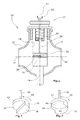
- the radiator valve device 10 has a housing 12 with a flow connection 14, which is connected to the heating flow.
- three openings 16, 18, 20 are formed.
- the first housing opening 16 is connected to a wall-side heating element of the radiator, not shown in the figure.
- the heating medium flowing out of the housing opening 16 is supplied to the heating element in its upper area.
- the housing opening 20 the exiting heating medium flows into a second, room-side heating element and is also supplied to this heating element in its upper region.
- the housing opening 18 is also connected to the second, room-side heating element, namely approximately halfway up the heating element.
- the heating medium supplied from the housing opening 20 completely flows through the room-side heating element from top to bottom and has already cooled at half height
- the heating medium from the housing opening 18 is fed to the room-side heating element approximately at half height.
- a conventional heating element can be uniformly heated over its entire height.
- a sleeve 24 is provided in the housing 12.
- the sleeve 24 is part of a valve insert 27 screwed into the housing 12.
- the sleeve 24 is provided with a slot 26 in the lateral surface thereof.
- the slot 26 is rectangular.
- the longitudinal direction of the elongated hole 26 extends in the circumferential direction of the sleeve 24.
- the width direction of the elongated hole 26 extends in the longitudinal direction of the sleeve 24.
- the width of the elongated hole 26 is 1.5 mm and its length 24 mm.
- a piston 32 is sealingly guided on a piston rod 30 on the inner wall of the sleeve 24.
- the piston is connected to a thermal expansion element of a thermostat sensor.
- the expansion element moves the piston 32 in a known manner, depending on the room temperature and setting of the thermostat knob, so that when reaching a desired room temperature, the piston 32, the slot 26 closes.
- no heating medium can then pass from the flow connection 14 into the heating elements.
- the piston 32 is in perspective view in FIG FIG. 2 shown. There, the opening portion 34 and the closing portion 36 of the piston 32 can be seen. Each of the two areas 34, 36 covers half of the circumferential direction of the piston 32, so that the areas 34, 36 are equal.
- the piston 32 In the opening area 34, the piston 32 has a lower height in the longitudinal direction parallel to the central longitudinal axis 22, as in the closing area 32.
- the piston 32 is in the in FIG. 2 rotatable by the arrow 40 shown circumferential direction.
- the closing region 36 conceals at least part of the oblong hole 26, the remaining part of the oblong hole 26 being released from the opening region 34.
- the height of the closing region 34 is at least equal to the width of the elongated hole 26, so that the opening portion 34 in the closed position of the piston, the slot 26 can completely close depending on the expansion element.
- the lifting movement of the piston 32 is limited by the stop 28.
- the piston 32 or the piston journal 30 is provided with a rotation stop, not shown in the figures, which limits the rotational movement of the piston 32.
- the rotation stop stops the rotation when the closing portion 36, the slot 26 completely closes.
- the piston rod 30 is provided at its rear, the piston 32 opposite end with an attack part 38 for applying a tool.
- the piston rod can be rotated.
- the engagement of the tool and the engagement member 38 can be done in a conventional manner, for example, as a toothed engagement.
- the tool and the valve core 27 may be provided with cooperating markings such as a scale to indicate the respective rotational position of the piston 32 relative to the slot 26.
- the sleeve 24 is sealed relative to the housing 12 such that the heating medium flows through the flow connection 14 into the interior of the sleeve 24.
- the heating medium flows from the sleeve 24 to the three housing openings 16, 18, 20 and through it into the respective heating elements.
- the housing openings 16, 18, 20 are of such size that a respective suitable volume flow flows into the respective heating element.
- the piston 32 of the second embodiment according to FIG. 3 is formed hollow cylindrical, wherein the opening portion 34 and the closing portion 36 are formed in the lateral surface 42 of the piston 32.
- the piston 32 of the first embodiment according to the Figures 1 and 2 is solid, the piston 32 of the second embodiment is according to FIG. 3 hollow.
- the cylindrical surface 42 which is cylindrical except for the steps through the opening region 34 and the closing region 36, is closed by an upper cover surface 44.
- On the upper deck surface 44 is the Piston rod 30 is arranged.
- the greater thickness of the piston 32 in the closing region 36 than the thickness in the opening region 34 is thus created by different lengths of the lateral surface 42.
- the length of the lateral surface 42 of the piston 32 is greater in the closing region 36 than in the opening region 34.
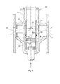
- the sleeve 24 is additionally provided with an inflow opening 50 and an outflow opening 52.
- a closure sleeve 54 is rotatably guided.
- the closing sleeve 54 is provided with a recess 56, which makes it possible, the outflow opening 52 in the in FIG. 4 to release shown rotational position of the closing sleeve 54 and to reduce the effective cross-section of the discharge opening 52 by turning the closing sleeve 54 and to close.
- the sleeve 24 is, similar to the first embodiment according to FIG. 1 Inserted in a housing 12 surrounding the sleeve. In addition, it is prevented by a suitable seal 58 that fluid flowing out of the slot 26 can pass directly into the first opening 16. Rather, the fluid flowing out of the slot 26 flows in part into the inlet opening 50 and to another part into the second opening 20 and from there into a room-side heating element connected to the second opening 20. The passing through the inlet opening 50 into the sleeve 24 fluid exits through the outflow opening 52 from the sleeve 24 and flows from there into the first opening 16 and into a connected to the first opening 16 wall-side heating element.
- the locking sleeve 54 By turning the locking sleeve 54, for example, with a conventional key for kV fine adjustment, thus reaching the wall-side heating element volume flow can be adjusted independently of the reaching into the room-side heating element flow.
- the closing sleeve 54 By turning the closing sleeve 54, the outflow opening 52 can be completely closed so that no fluid enters the wall-side heating element. This may be beneficial in the transitional period to the completely block the wall-side heating element and only heat it via the room-side heating element.
- the piston rod 30 is provided in the region of its rear, the piston 32 opposite end with an adapter which can engage with a thermostatic head also not shown in the figures such that a rotation of the thermostatic head a corresponding Rotation of the piston rod 30 causes.
- the thermostatic head may be formed in a known manner to set the desired room temperature by setting a certain rotational position of the thermostatic head. Depending on the rotational position of the thermostatic head 30 and the effective opening cross-section of the elongated hole 26 is changed via appropriate rotation of the piston rod.
- the rotary engagement is designed such that reducing the room temperature by corresponding rotation of the thermostatic head reduces the effective opening cross section of the elongated hole 26 and thus the volume flow flowing through the slot 26.
- the effective opening cross-section of the elongated hole 26 and the volume through the slot 26 is then automatically increased.
- the plumbing installer will first make a suitable KV volumetric flow adjustment by turning the plunger, for example by means of a suitable key suitable for a mean room set temperature of, for example, 20 degrees. By changing the desired room temperature by turning the thermostatic head then fine adjustment of the volume flow is automatically made to adapt to the respective desired room temperature.
Landscapes
- Engineering & Computer Science (AREA)
- General Engineering & Computer Science (AREA)
- Mechanical Engineering (AREA)
- Physics & Mathematics (AREA)
- Thermal Sciences (AREA)
- Chemical & Material Sciences (AREA)
- Combustion & Propulsion (AREA)
- Temperature-Responsive Valves (AREA)
- Lift Valve (AREA)
Priority Applications (2)
| Application Number | Priority Date | Filing Date | Title |
|---|---|---|---|
| EP17167939.2A EP3222920A1 (fr) | 2014-02-27 | 2015-02-27 | Vanne thermostatique présentant un trou oblong |
| EP17167957.4A EP3222921A1 (fr) | 2014-02-27 | 2015-02-27 | Vanne thermostatique présentant un trou oblong |
Applications Claiming Priority (1)
| Application Number | Priority Date | Filing Date | Title |
|---|---|---|---|
| DE102014203548.1A DE102014203548A1 (de) | 2014-02-27 | 2014-02-27 | Heizkörperventilvorrichtung mit Langloch |
Related Child Applications (2)
| Application Number | Title | Priority Date | Filing Date |
|---|---|---|---|
| EP17167957.4A Division EP3222921A1 (fr) | 2014-02-27 | 2015-02-27 | Vanne thermostatique présentant un trou oblong |
| EP17167939.2A Division EP3222920A1 (fr) | 2014-02-27 | 2015-02-27 | Vanne thermostatique présentant un trou oblong |
Publications (2)
| Publication Number | Publication Date |
|---|---|
| EP2913595A1 true EP2913595A1 (fr) | 2015-09-02 |
| EP2913595B1 EP2913595B1 (fr) | 2017-04-26 |
Family
ID=52573608
Family Applications (3)
| Application Number | Title | Priority Date | Filing Date |
|---|---|---|---|
| EP17167957.4A Withdrawn EP3222921A1 (fr) | 2014-02-27 | 2015-02-27 | Vanne thermostatique présentant un trou oblong |
| EP17167939.2A Withdrawn EP3222920A1 (fr) | 2014-02-27 | 2015-02-27 | Vanne thermostatique présentant un trou oblong |
| EP15156960.5A Not-in-force EP2913595B1 (fr) | 2014-02-27 | 2015-02-27 | Robinet de radiateur présentant un trou oblong |
Family Applications Before (2)
| Application Number | Title | Priority Date | Filing Date |
|---|---|---|---|
| EP17167957.4A Withdrawn EP3222921A1 (fr) | 2014-02-27 | 2015-02-27 | Vanne thermostatique présentant un trou oblong |
| EP17167939.2A Withdrawn EP3222920A1 (fr) | 2014-02-27 | 2015-02-27 | Vanne thermostatique présentant un trou oblong |
Country Status (2)
| Country | Link |
|---|---|
| EP (3) | EP3222921A1 (fr) |
| DE (1) | DE102014203548A1 (fr) |
Families Citing this family (1)
| Publication number | Priority date | Publication date | Assignee | Title |
|---|---|---|---|---|
| DE202016006831U1 (de) | 2016-11-09 | 2016-12-01 | Hans-Alfred Balg | Heizkörper mit zwei Heizkörperelementen mit verschiedener Höhenerstreckung |
Citations (6)
| Publication number | Priority date | Publication date | Assignee | Title |
|---|---|---|---|---|
| GB948738A (en) * | 1959-05-22 | 1964-02-05 | Filip Emanuel Odell | Improvements in or relating to a radiator valve |
| US20080245428A1 (en) * | 2005-06-23 | 2008-10-09 | Frese A/S | Control Valve |
| US20090199905A1 (en) * | 2006-06-12 | 2009-08-13 | Tour & Andersson Ab | Regulating valve with maintained regulating characteristic at different kv-values within one and the same valve |
| US20090321672A1 (en) * | 2006-11-02 | 2009-12-31 | Bjarne Wittendorf Ibsen | Adjustable Regulator Insert |
| DE102011084297A1 (de) * | 2011-10-11 | 2013-04-11 | Hans-Alfred Balg | Anschlusskörper für einen Heizkörper |
| EP2696145A1 (fr) * | 2012-08-10 | 2014-02-12 | KERMI GmbH | Garniture de soupape de radiateur |
-
2014
- 2014-02-27 DE DE102014203548.1A patent/DE102014203548A1/de not_active Withdrawn
-
2015
- 2015-02-27 EP EP17167957.4A patent/EP3222921A1/fr not_active Withdrawn
- 2015-02-27 EP EP17167939.2A patent/EP3222920A1/fr not_active Withdrawn
- 2015-02-27 EP EP15156960.5A patent/EP2913595B1/fr not_active Not-in-force
Patent Citations (6)
| Publication number | Priority date | Publication date | Assignee | Title |
|---|---|---|---|---|
| GB948738A (en) * | 1959-05-22 | 1964-02-05 | Filip Emanuel Odell | Improvements in or relating to a radiator valve |
| US20080245428A1 (en) * | 2005-06-23 | 2008-10-09 | Frese A/S | Control Valve |
| US20090199905A1 (en) * | 2006-06-12 | 2009-08-13 | Tour & Andersson Ab | Regulating valve with maintained regulating characteristic at different kv-values within one and the same valve |
| US20090321672A1 (en) * | 2006-11-02 | 2009-12-31 | Bjarne Wittendorf Ibsen | Adjustable Regulator Insert |
| DE102011084297A1 (de) * | 2011-10-11 | 2013-04-11 | Hans-Alfred Balg | Anschlusskörper für einen Heizkörper |
| EP2696145A1 (fr) * | 2012-08-10 | 2014-02-12 | KERMI GmbH | Garniture de soupape de radiateur |
Also Published As
| Publication number | Publication date |
|---|---|
| EP3222921A1 (fr) | 2017-09-27 |
| EP2913595B1 (fr) | 2017-04-26 |
| DE102014203548A1 (de) | 2015-08-27 |
| EP3222920A1 (fr) | 2017-09-27 |
Similar Documents
| Publication | Publication Date | Title |
|---|---|---|
| DE2953331C1 (de) | Steuerungs- und Absperrventil fuer stroemende Medien | |
| DE60209666T2 (de) | Vierteldrehungsthermostatischekartusche mit konzentrischem Antrieb, mit keramischen Scheiben, und eine Mischbatterie die diese enthält | |
| EP2226697B1 (fr) | Régulateur de débit | |
| DE3202113C2 (de) | Mischventil für sanitäre Einhebel-Mischbatterie | |
| DE4208241A1 (de) | Thermostatisch geregeltes mischventil | |
| WO2018145905A1 (fr) | Vanne de mélange thermostatique | |
| EP3021023B1 (fr) | Robinetterie ayant un axe de pivotement decale d'element de commande | |
| EP1859329B1 (fr) | Regulateur de debit | |
| DE2350375A1 (de) | Ventil | |
| DE10056715C2 (de) | Ventil für Warmwasseranlagen | |
| EP2913595B1 (fr) | Robinet de radiateur présentant un trou oblong | |
| DE2741280C2 (de) | Ventilanbohrschelle | |
| EP2461223B1 (fr) | Mélangeur thermostatique | |
| DE102005011947B3 (de) | Durchflussmengenregler | |
| DE102006026336B4 (de) | Einbauventil für einen Heizkörper | |
| DE4324158A1 (de) | Fluidventil | |
| DE2050025B2 (de) | Eingriff Mischbatterie | |
| DE10202560B4 (de) | Thermostat-Mischventil | |
| DE102011015781A1 (de) | Drosselventil | |
| DE2627923A1 (de) | Mischarmatur fuer kalt- und warmwasser | |
| AT517600B1 (de) | Einbauventil | |
| DE2614063B2 (de) | Mischventil der huelsenbauart | |
| DE102006020184B4 (de) | Regelventil | |
| DE102006056909B4 (de) | Heizkörperventil | |
| EP3112540A1 (fr) | Partie superieure de soupape |
Legal Events
| Date | Code | Title | Description |
|---|---|---|---|
| PUAI | Public reference made under article 153(3) epc to a published international application that has entered the european phase |
Free format text: ORIGINAL CODE: 0009012 |
|
| AK | Designated contracting states |
Kind code of ref document: A1 Designated state(s): AL AT BE BG CH CY CZ DE DK EE ES FI FR GB GR HR HU IE IS IT LI LT LU LV MC MK MT NL NO PL PT RO RS SE SI SK SM TR |
|
| AX | Request for extension of the european patent |
Extension state: BA ME |
|
| 17P | Request for examination filed |
Effective date: 20160211 |
|
| RBV | Designated contracting states (corrected) |
Designated state(s): AL AT BE BG CH CY CZ DE DK EE ES FI FR GB GR HR HU IE IS IT LI LT LU LV MC MK MT NL NO PL PT RO RS SE SI SK SM TR |
|
| GRAP | Despatch of communication of intention to grant a patent |
Free format text: ORIGINAL CODE: EPIDOSNIGR1 |
|
| STAA | Information on the status of an ep patent application or granted ep patent |
Free format text: STATUS: GRANT OF PATENT IS INTENDED |
|
| RIC1 | Information provided on ipc code assigned before grant |
Ipc: F16K 5/10 20060101ALI20161031BHEP Ipc: F16K 3/32 20060101ALI20161031BHEP Ipc: F16K 3/24 20060101ALI20161031BHEP Ipc: F24D 19/00 20060101AFI20161031BHEP Ipc: F24D 19/10 20060101ALI20161031BHEP |
|
| INTG | Intention to grant announced |
Effective date: 20161118 |
|
| GRAS | Grant fee paid |
Free format text: ORIGINAL CODE: EPIDOSNIGR3 |
|
| GRAA | (expected) grant |
Free format text: ORIGINAL CODE: 0009210 |
|
| STAA | Information on the status of an ep patent application or granted ep patent |
Free format text: STATUS: THE PATENT HAS BEEN GRANTED |
|
| AK | Designated contracting states |
Kind code of ref document: B1 Designated state(s): AL AT BE BG CH CY CZ DE DK EE ES FI FR GB GR HR HU IE IS IT LI LT LU LV MC MK MT NL NO PL PT RO RS SE SI SK SM TR |
|
| REG | Reference to a national code |
Ref country code: GB Ref legal event code: FG4D Free format text: NOT ENGLISH |
|
| REG | Reference to a national code |
Ref country code: CH Ref legal event code: EP |
|
| REG | Reference to a national code |
Ref country code: AT Ref legal event code: REF Ref document number: 888229 Country of ref document: AT Kind code of ref document: T Effective date: 20170515 |
|
| REG | Reference to a national code |
Ref country code: IE Ref legal event code: FG4D Free format text: LANGUAGE OF EP DOCUMENT: GERMAN |
|
| REG | Reference to a national code |
Ref country code: DE Ref legal event code: R096 Ref document number: 502015000914 Country of ref document: DE |
|
| REG | Reference to a national code |
Ref country code: CH Ref legal event code: NV Representative=s name: ISLER AND PEDRAZZINI AG, CH |
|
| REG | Reference to a national code |
Ref country code: NL Ref legal event code: FP |
|
| REG | Reference to a national code |
Ref country code: LT Ref legal event code: MG4D |
|
| PG25 | Lapsed in a contracting state [announced via postgrant information from national office to epo] |
Ref country code: LT Free format text: LAPSE BECAUSE OF FAILURE TO SUBMIT A TRANSLATION OF THE DESCRIPTION OR TO PAY THE FEE WITHIN THE PRESCRIBED TIME-LIMIT Effective date: 20170426 Ref country code: NO Free format text: LAPSE BECAUSE OF FAILURE TO SUBMIT A TRANSLATION OF THE DESCRIPTION OR TO PAY THE FEE WITHIN THE PRESCRIBED TIME-LIMIT Effective date: 20170726 Ref country code: HR Free format text: LAPSE BECAUSE OF FAILURE TO SUBMIT A TRANSLATION OF THE DESCRIPTION OR TO PAY THE FEE WITHIN THE PRESCRIBED TIME-LIMIT Effective date: 20170426 Ref country code: GR Free format text: LAPSE BECAUSE OF FAILURE TO SUBMIT A TRANSLATION OF THE DESCRIPTION OR TO PAY THE FEE WITHIN THE PRESCRIBED TIME-LIMIT Effective date: 20170727 Ref country code: FI Free format text: LAPSE BECAUSE OF FAILURE TO SUBMIT A TRANSLATION OF THE DESCRIPTION OR TO PAY THE FEE WITHIN THE PRESCRIBED TIME-LIMIT Effective date: 20170426 Ref country code: ES Free format text: LAPSE BECAUSE OF FAILURE TO SUBMIT A TRANSLATION OF THE DESCRIPTION OR TO PAY THE FEE WITHIN THE PRESCRIBED TIME-LIMIT Effective date: 20170426 |
|
| PG25 | Lapsed in a contracting state [announced via postgrant information from national office to epo] |
Ref country code: SE Free format text: LAPSE BECAUSE OF FAILURE TO SUBMIT A TRANSLATION OF THE DESCRIPTION OR TO PAY THE FEE WITHIN THE PRESCRIBED TIME-LIMIT Effective date: 20170426 Ref country code: PL Free format text: LAPSE BECAUSE OF FAILURE TO SUBMIT A TRANSLATION OF THE DESCRIPTION OR TO PAY THE FEE WITHIN THE PRESCRIBED TIME-LIMIT Effective date: 20170426 Ref country code: LV Free format text: LAPSE BECAUSE OF FAILURE TO SUBMIT A TRANSLATION OF THE DESCRIPTION OR TO PAY THE FEE WITHIN THE PRESCRIBED TIME-LIMIT Effective date: 20170426 Ref country code: IS Free format text: LAPSE BECAUSE OF FAILURE TO SUBMIT A TRANSLATION OF THE DESCRIPTION OR TO PAY THE FEE WITHIN THE PRESCRIBED TIME-LIMIT Effective date: 20170826 Ref country code: BG Free format text: LAPSE BECAUSE OF FAILURE TO SUBMIT A TRANSLATION OF THE DESCRIPTION OR TO PAY THE FEE WITHIN THE PRESCRIBED TIME-LIMIT Effective date: 20170726 Ref country code: RS Free format text: LAPSE BECAUSE OF FAILURE TO SUBMIT A TRANSLATION OF THE DESCRIPTION OR TO PAY THE FEE WITHIN THE PRESCRIBED TIME-LIMIT Effective date: 20170426 |
|
| REG | Reference to a national code |
Ref country code: DE Ref legal event code: R097 Ref document number: 502015000914 Country of ref document: DE |
|
| PG25 | Lapsed in a contracting state [announced via postgrant information from national office to epo] |
Ref country code: EE Free format text: LAPSE BECAUSE OF FAILURE TO SUBMIT A TRANSLATION OF THE DESCRIPTION OR TO PAY THE FEE WITHIN THE PRESCRIBED TIME-LIMIT Effective date: 20170426 Ref country code: CZ Free format text: LAPSE BECAUSE OF FAILURE TO SUBMIT A TRANSLATION OF THE DESCRIPTION OR TO PAY THE FEE WITHIN THE PRESCRIBED TIME-LIMIT Effective date: 20170426 Ref country code: DK Free format text: LAPSE BECAUSE OF FAILURE TO SUBMIT A TRANSLATION OF THE DESCRIPTION OR TO PAY THE FEE WITHIN THE PRESCRIBED TIME-LIMIT Effective date: 20170426 Ref country code: SK Free format text: LAPSE BECAUSE OF FAILURE TO SUBMIT A TRANSLATION OF THE DESCRIPTION OR TO PAY THE FEE WITHIN THE PRESCRIBED TIME-LIMIT Effective date: 20170426 Ref country code: RO Free format text: LAPSE BECAUSE OF FAILURE TO SUBMIT A TRANSLATION OF THE DESCRIPTION OR TO PAY THE FEE WITHIN THE PRESCRIBED TIME-LIMIT Effective date: 20170426 |
|
| PG25 | Lapsed in a contracting state [announced via postgrant information from national office to epo] |
Ref country code: SM Free format text: LAPSE BECAUSE OF FAILURE TO SUBMIT A TRANSLATION OF THE DESCRIPTION OR TO PAY THE FEE WITHIN THE PRESCRIBED TIME-LIMIT Effective date: 20170426 Ref country code: IT Free format text: LAPSE BECAUSE OF FAILURE TO SUBMIT A TRANSLATION OF THE DESCRIPTION OR TO PAY THE FEE WITHIN THE PRESCRIBED TIME-LIMIT Effective date: 20170426 |
|
| PLBE | No opposition filed within time limit |
Free format text: ORIGINAL CODE: 0009261 |
|
| STAA | Information on the status of an ep patent application or granted ep patent |
Free format text: STATUS: NO OPPOSITION FILED WITHIN TIME LIMIT |
|
| 26N | No opposition filed |
Effective date: 20180129 |
|
| PG25 | Lapsed in a contracting state [announced via postgrant information from national office to epo] |
Ref country code: SI Free format text: LAPSE BECAUSE OF FAILURE TO SUBMIT A TRANSLATION OF THE DESCRIPTION OR TO PAY THE FEE WITHIN THE PRESCRIBED TIME-LIMIT Effective date: 20170426 |
|
| REG | Reference to a national code |
Ref country code: DE Ref legal event code: R119 Ref document number: 502015000914 Country of ref document: DE |
|
| REG | Reference to a national code |
Ref country code: CH Ref legal event code: PL |
|
| PG25 | Lapsed in a contracting state [announced via postgrant information from national office to epo] |
Ref country code: MT Free format text: LAPSE BECAUSE OF FAILURE TO SUBMIT A TRANSLATION OF THE DESCRIPTION OR TO PAY THE FEE WITHIN THE PRESCRIBED TIME-LIMIT Effective date: 20170426 Ref country code: MC Free format text: LAPSE BECAUSE OF FAILURE TO SUBMIT A TRANSLATION OF THE DESCRIPTION OR TO PAY THE FEE WITHIN THE PRESCRIBED TIME-LIMIT Effective date: 20170426 |
|
| REG | Reference to a national code |
Ref country code: NL Ref legal event code: MM Effective date: 20180301 |
|
| REG | Reference to a national code |
Ref country code: IE Ref legal event code: MM4A |
|
| REG | Reference to a national code |
Ref country code: BE Ref legal event code: MM Effective date: 20180228 |
|
| PG25 | Lapsed in a contracting state [announced via postgrant information from national office to epo] |
Ref country code: LU Free format text: LAPSE BECAUSE OF NON-PAYMENT OF DUE FEES Effective date: 20180227 Ref country code: CH Free format text: LAPSE BECAUSE OF NON-PAYMENT OF DUE FEES Effective date: 20180228 Ref country code: LI Free format text: LAPSE BECAUSE OF NON-PAYMENT OF DUE FEES Effective date: 20180228 |
|
| REG | Reference to a national code |
Ref country code: FR Ref legal event code: ST Effective date: 20181031 |
|
| PG25 | Lapsed in a contracting state [announced via postgrant information from national office to epo] |
Ref country code: NL Free format text: LAPSE BECAUSE OF NON-PAYMENT OF DUE FEES Effective date: 20180301 |
|
| PG25 | Lapsed in a contracting state [announced via postgrant information from national office to epo] |
Ref country code: IE Free format text: LAPSE BECAUSE OF NON-PAYMENT OF DUE FEES Effective date: 20180227 Ref country code: DE Free format text: LAPSE BECAUSE OF NON-PAYMENT OF DUE FEES Effective date: 20180901 |
|
| PG25 | Lapsed in a contracting state [announced via postgrant information from national office to epo] |
Ref country code: BE Free format text: LAPSE BECAUSE OF NON-PAYMENT OF DUE FEES Effective date: 20180228 Ref country code: FR Free format text: LAPSE BECAUSE OF NON-PAYMENT OF DUE FEES Effective date: 20180228 |
|
| GBPC | Gb: european patent ceased through non-payment of renewal fee |
Effective date: 20190227 |
|
| PG25 | Lapsed in a contracting state [announced via postgrant information from national office to epo] |
Ref country code: GB Free format text: LAPSE BECAUSE OF NON-PAYMENT OF DUE FEES Effective date: 20190227 |
|
| PG25 | Lapsed in a contracting state [announced via postgrant information from national office to epo] |
Ref country code: TR Free format text: LAPSE BECAUSE OF FAILURE TO SUBMIT A TRANSLATION OF THE DESCRIPTION OR TO PAY THE FEE WITHIN THE PRESCRIBED TIME-LIMIT Effective date: 20170426 |
|
| PG25 | Lapsed in a contracting state [announced via postgrant information from national office to epo] |
Ref country code: PT Free format text: LAPSE BECAUSE OF FAILURE TO SUBMIT A TRANSLATION OF THE DESCRIPTION OR TO PAY THE FEE WITHIN THE PRESCRIBED TIME-LIMIT Effective date: 20170426 |
|
| PG25 | Lapsed in a contracting state [announced via postgrant information from national office to epo] |
Ref country code: CY Free format text: LAPSE BECAUSE OF FAILURE TO SUBMIT A TRANSLATION OF THE DESCRIPTION OR TO PAY THE FEE WITHIN THE PRESCRIBED TIME-LIMIT Effective date: 20170426 Ref country code: MK Free format text: LAPSE BECAUSE OF NON-PAYMENT OF DUE FEES Effective date: 20170426 Ref country code: HU Free format text: LAPSE BECAUSE OF FAILURE TO SUBMIT A TRANSLATION OF THE DESCRIPTION OR TO PAY THE FEE WITHIN THE PRESCRIBED TIME-LIMIT; INVALID AB INITIO Effective date: 20150227 |
|
| PG25 | Lapsed in a contracting state [announced via postgrant information from national office to epo] |
Ref country code: AL Free format text: LAPSE BECAUSE OF FAILURE TO SUBMIT A TRANSLATION OF THE DESCRIPTION OR TO PAY THE FEE WITHIN THE PRESCRIBED TIME-LIMIT Effective date: 20170426 |
|
| REG | Reference to a national code |
Ref country code: AT Ref legal event code: MM01 Ref document number: 888229 Country of ref document: AT Kind code of ref document: T Effective date: 20200227 |
|
| PG25 | Lapsed in a contracting state [announced via postgrant information from national office to epo] |
Ref country code: AT Free format text: LAPSE BECAUSE OF NON-PAYMENT OF DUE FEES Effective date: 20200227 |