EP2913632A1 - Verfahren zur Messung eines Messobjektes mittels Röntgenfluoreszenz - Google Patents
Verfahren zur Messung eines Messobjektes mittels Röntgenfluoreszenz Download PDFInfo
- Publication number
- EP2913632A1 EP2913632A1 EP15151728.1A EP15151728A EP2913632A1 EP 2913632 A1 EP2913632 A1 EP 2913632A1 EP 15151728 A EP15151728 A EP 15151728A EP 2913632 A1 EP2913632 A1 EP 2913632A1
- Authority
- EP
- European Patent Office
- Prior art keywords
- measuring
- size
- raster
- sub
- determined
- Prior art date
- Legal status (The legal status is an assumption and is not a legal conclusion. Google has not performed a legal analysis and makes no representation as to the accuracy of the status listed.)
- Granted
Links
Images
Classifications
-
- G—PHYSICS
- G01—MEASURING; TESTING
- G01N—INVESTIGATING OR ANALYSING MATERIALS BY DETERMINING THEIR CHEMICAL OR PHYSICAL PROPERTIES
- G01N23/00—Investigating or analysing materials by the use of wave or particle radiation, e.g. X-rays or neutrons, not covered by groups G01N3/00 – G01N17/00, G01N21/00 or G01N22/00
- G01N23/22—Investigating or analysing materials by the use of wave or particle radiation, e.g. X-rays or neutrons, not covered by groups G01N3/00 – G01N17/00, G01N21/00 or G01N22/00 by measuring secondary emission from the material
- G01N23/223—Investigating or analysing materials by the use of wave or particle radiation, e.g. X-rays or neutrons, not covered by groups G01N3/00 – G01N17/00, G01N21/00 or G01N22/00 by measuring secondary emission from the material by irradiating the sample with X-rays or gamma-rays and by measuring X-ray fluorescence
-
- G—PHYSICS
- G01—MEASURING; TESTING
- G01D—MEASURING NOT SPECIALLY ADAPTED FOR A SPECIFIC VARIABLE; ARRANGEMENTS FOR MEASURING TWO OR MORE VARIABLES NOT COVERED IN A SINGLE OTHER SUBCLASS; TARIFF METERING APPARATUS; MEASURING OR TESTING NOT OTHERWISE PROVIDED FOR
- G01D21/00—Measuring or testing not otherwise provided for
- G01D21/02—Measuring two or more variables by means not covered by a single other subclass
-
- G—PHYSICS
- G01—MEASURING; TESTING
- G01B—MEASURING LENGTH, THICKNESS OR SIMILAR LINEAR DIMENSIONS; MEASURING ANGLES; MEASURING AREAS; MEASURING IRREGULARITIES OF SURFACES OR CONTOURS
- G01B15/00—Measuring arrangements characterised by the use of electromagnetic waves or particle radiation, e.g. by the use of microwaves, X-rays, gamma rays or electrons
- G01B15/02—Measuring arrangements characterised by the use of electromagnetic waves or particle radiation, e.g. by the use of microwaves, X-rays, gamma rays or electrons for measuring thickness
-
- G—PHYSICS
- G01—MEASURING; TESTING
- G01N—INVESTIGATING OR ANALYSING MATERIALS BY DETERMINING THEIR CHEMICAL OR PHYSICAL PROPERTIES
- G01N2223/00—Investigating materials by wave or particle radiation
- G01N2223/07—Investigating materials by wave or particle radiation secondary emission
- G01N2223/076—X-ray fluorescence
-
- G—PHYSICS
- G01—MEASURING; TESTING
- G01N—INVESTIGATING OR ANALYSING MATERIALS BY DETERMINING THEIR CHEMICAL OR PHYSICAL PROPERTIES
- G01N2223/00—Investigating materials by wave or particle radiation
- G01N2223/60—Specific applications or type of materials
- G01N2223/611—Specific applications or type of materials patterned objects; electronic devices
- G01N2223/6113—Specific applications or type of materials patterned objects; electronic devices printed circuit board [PCB]
-
- G—PHYSICS
- G01—MEASURING; TESTING
- G01N—INVESTIGATING OR ANALYSING MATERIALS BY DETERMINING THEIR CHEMICAL OR PHYSICAL PROPERTIES
- G01N2223/00—Investigating materials by wave or particle radiation
- G01N2223/60—Specific applications or type of materials
- G01N2223/633—Specific applications or type of materials thickness, density, surface weight (unit area)
Definitions
- the invention relates to a method for measuring a measurement object by means of X-ray fluorescence, in particular for measuring the thickness and elemental composition of thin layers of a measurement object.
- a primary beam is directed from a radiation source to the measurement object.
- a secondary radiation emitted by the measurement surface is detected by a detector and forwarded to the evaluation device, for example to determine the layer thickness.
- the size of the primary beam is adapted to the structure size of the measurement object, wherein the measurement of small structures then finds its limit when the exciting primary beam is greater in its lateral extent than the flat surface of the measurement object. This means that the smaller the measuring object, the smaller the measuring spot of the primary beam must be. This could be done by masking the exciting beam of the primary beam, which, however, is accompanied by a reduction of the intensity and thereby an impairment in the detection of the spectrum of the secondary radiation. As a result, there are limits to this conventional technology.
- the invention is therefore based on the object to enable a method for measuring DUTs with a smaller dimension, in particular cost-effective.
- This object is achieved according to the invention by a method by means of X-ray fluorescence, in which a size of the measuring surface of the measuring object is detected, then the size of the measuring surface of the measuring object is compared with a size of a measuring spot of the primary beam impinging on the measuring object and during the determination a measurement area which is smaller than the measurement spot, a size of the grid surface is selected, which covers at least the measuring surface of the measurement object, wherein from the ratio of the grid surface to the surface of the measurement object, a scaling factor ⁇ is determined, which with the recorded spectra of the individual measurements multiplied by the respective raster sub-areas after summing up and their averaging and then the spectrum corrected by the scaling factor ⁇ is provided for the quantitative evaluation.
- a detection of a measurement surface of the measurement object which lies only partially within a raster sub-area, be included in the evaluation, so that due to the ratio of the size of the grid area and the size of the measuring surface a scaling factor ⁇ serves as a correction factor to evaluate the individual determined spectra of secondary radiation within the grid sub-areas of the grid.
- the distance of the raster sub-area is determined by the size of the measurement spot of the primary beam, which impinges on the measurement object. This requires no additional adjustment or modification of an appearance. Rather, the size of the measuring spot is determined device-specifically in X-ray fluorescence, so that thereby a device-side secured size is given, which is used for the process.
- the size of the raster area is preferably formed from an integral multiple of measurement spots of the primary beam arranged directly adjacent to one another or overlapping.
- a grid area with only one row or one column can be formed from a plurality of measurement spots arranged next to one another or next to one another. It is also possible to provide a matrix of both an identical and a different number of rows and columns with measurement spots arranged in any direction.
- This grid surface can be adapted to the measurement task or to the contour of the measurement surface of the measurement object. In any case, each raster sub-area is at least filled by a measuring spot.
- the corrected spectra of the secondary radiation from the individual measurements of the raster sub-areas are preferably evaluated by means of evaluation software, so that an element concentration or layer thickness of the coating or a layer on a base material is determined and output therefrom. This makes it possible to carry out a simple check as to whether a coating on a base material is adequate with respect to the layer thickness and / or sufficiently with respect to the individual element concentrations.
- a further advantageous embodiment of the method provides that a trajectory of Rastererteil arrangements to Rastererteil composition within one row or one column or from one row or column into the next column or row within the grid area is determined by the size of the measuring spot of the primary beam of the radiation source.
- the measuring spot of the primary beam is determined by a so-called primary spot on an anode of the X-ray tube. Due to the travel distance from the raster sub-area to the raster sub-area, the raster area can be detected completely with respect to the entire area, so that transitions with respect to the presence and absence of layers to be measured can also be detected.
- the size of the measurement surface of the measurement object is preferably determined by an optical measurement method. As a result, an exact determination can be made possible in a simple manner in order to use this size of the measuring surface for the determination of the scaling factor.
- the size of the grid area is determined to be greater than the determined measuring area of the test object, wherein the grid area at least partially surrounds the determined measuring area from an edge, at least in sections.
- This edge serves to provide at least a transition from an area not to be detected and the measuring surface of the measurement object in order to detect and take into account a change in intensity.
- the edge surrounding the measurement surface of the measurement object at least partially has a width of at least one size of a raster sub-area.
- the raster surface is larger than the measuring surface by at least two raster sub-areas, so that an edge is formed on each side edge.
- a raster sub-area has the size of a so-called half-width (FWHM), which are specific to each X-ray fluorescence device.
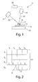
- FIG. 1 schematically a device 11 for performing an X-ray fluorescence analysis with a sample body 12 is shown.
- This may be, for example, a printed circuit board with bond pads.
- the bonding pad may consist of a narrow copper bar 14 on a printed circuit board.
- a nickel layer 17 is applied, which is coated with a gold layer 18 to avoid corrosion. At least the gold layer 18 and usually also the nickel layer 17 are to be measured and tested in such an embodiment with respect to the layer thickness and the element concentrations.
- This device 11 comprises an X-ray source 21 or an X-ray tube, via which a primary radiation 22 is output and directed onto the sample body 12, which may be received by a sample carrier 23, for example.
- the sample carrier 23 may be adjustable in position and / or in height, preferably by means of a movable table, which in particular is motor-driven.
- the primary beam 22 can be focused, for example via a collimator, not shown.
- the primary beam 22 is directed, for example, perpendicularly or at an angle deviating therefrom to the surface of the sample body 12 onto a measurement object 24 of the sample body 12.
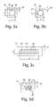
- FIG. 2 is a schematic view from above of a measuring object 24 with a measuring surface 25 shown.
- the size of such a measurement object 24 may include, for example, a length and / or width of 60 microns or 50 microns or less.
- a raster surface 31 of a plurality of raster sub-areas 1, 2, 3, 4... N is determined, which in rows Z1... Zn and / or columns S1 are arranged.
- an optical detection of the measuring surface 25 of the test object 24 is initially carried out.
- an optical measuring device in particular a microscope or a scanning electron microscope, can be used.
- the grid surface 31 is determined.
- the optically determined size of the measuring surface 25 of the measuring object 24 is compared with a size of a measuring spot 36 of the primary beam 22 which occurs on the measuring surface 25 of the measuring object 24.
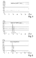
- the size of the measuring spot 36 is usually indicated as the half width (FWHM). This size is device specific and is determined by the primary spot, the beam optics, and the geometry in the anode associated with the radiation source. If the size of the measuring spot 36 is smaller than that of the measuring area 25, a grid area 31 is determined which is larger than the measuring area 25 and advantageously has an edge 35 which is described in the following FIGS. 3a to 3c for different geometries of the measuring surface 25 is shown.
- FWHM half width
- a uniform circumferential edge 35 is provided so that the raster surface 31 with respect to its side edge is made up of the edge length a of the measuring surface 25 and twice the edge 35 composed.
- Figure 3c For example, a rectangular measuring surface 25 is shown in which the length of the side edge a deviates significantly from the length of the side edge b.
- the peripheral edge 35 is analogous to FIG. 3a formed to determine the grid surface 31.
- the spacings of the measuring objects 24 are smaller than the size of the measuring spot 36.
- a plurality of measuring objects 24 are combined to form a total measuring area and, in addition, the circumferential edge 35 in analogy to FIG. 3a formed to determine the grid surface 31.
- the width of the edge 35 is advantageously designed such that it covers the size of at least one measuring spot 36. Alternatively, the edge 35 may be wider. Based on the determined size of the measuring surface 25 and twice the value of a measuring spot 36 for the right and left edge 35, the number of individual raster sub-areas within at least one row Z1 to Zn and / or at least one column S1 to Sn is determined thereon, wherein the number the raster sub-areas resulting from an integral multiple of the size of the measuring spot 36, as shown for example in FIG. 2 is shown. The distance of the raster sub-areas corresponds to the size of the measuring spot 36, so that a full-surface scanning of the grid surfaces 31 with the primary beam 22 for detecting the spectra of the secondary radiation 26 from the individual measurements is possible.
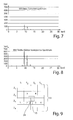
- the primary beam 22 is directed onto the raster sub-area 1, which is in the position Z3 / S1 of the raster area 31. Subsequently, will the measuring object 24 is moved by one nip width to the left, so that the primary beam 22 enters the raster sub-area 2. This is repeated until the raster sub-areas 3 and 4 have been irradiated, so that by means of the detector 27, the respective spectrum is detected. This results, for example, for the raster sub-areas 1 and 4 in the FIG. 4 illustrated spectrum. Since a measuring surface 25 of the test object 24 was not included in the raster sub-areas 1 and 4, there is no acquisition of measured values in this regard and thus no output of signals.
- FIG. 5 the spectrum of the raster sub-areas 2 and 3 is shown. Since the raster sub-areas 2 and 3 each cover a part of the measuring surface 25 of the measuring object 24, the spectrum thus determined is detected accordingly.
- This exemplary acquisition of the spectra in the raster sub-areas 1 to 4 in line 3 is carried out for all raster sub-areas within the raster area 31.
- a line-by-line detection of the spectra it is also possible to perform a column-wise detection of the spectra of the secondary radiation 26 in the individual raster sub-areas of the raster area 31.
- the detected spectra are then evaluated in the respective raster sub-areas of the raster area 31.
- a sum spectrum is formed, which in the example of the raster sub-areas 1 to 4 in FIG. 6 exists and is shown. This corresponds in this case to the FIG. 5 because no spectrum was determined in the raster sub-areas 1 and 4.
- the entire grid area would be taken into account, resulting from the points Z3 / S2 and Z3 / S3 also a spectrum that would be summed up.
- the measuring surface 25 of the test object 24 is moved by the amount of the measuring spot 36 or the raster sub-area by motor, so that an immediate juxtaposition of the individual measuring spots 36 is made possible.
- a positioning table is preferably provided, which has such a resolution for the individual traversing steps, which corresponds to the size of the measuring spot 36.
- FIG. 9 is a practical example shown, as it usually occurs and of FIG. 2 with respect to the positioning of the raster sub-areas for lateral expansion of the measurement object 24 deviates.
- the spectra determined in the raster sub-areas 2, 3, 5 and 6 are summarized and then evaluated in analogy to the method described above.
Landscapes
- Physics & Mathematics (AREA)
- General Physics & Mathematics (AREA)
- General Health & Medical Sciences (AREA)
- Chemical & Material Sciences (AREA)
- Analytical Chemistry (AREA)
- Biochemistry (AREA)
- Life Sciences & Earth Sciences (AREA)
- Health & Medical Sciences (AREA)
- Immunology (AREA)
- Pathology (AREA)
- Electromagnetism (AREA)
- Analysing Materials By The Use Of Radiation (AREA)
- Length-Measuring Devices Using Wave Or Particle Radiation (AREA)
Abstract
Description
- Die Erfindung betrifft ein Verfahren zur Messung eines Messobjektes mittels Röntgenfluoreszenz, insbesondere zur Messung der Dicke und Elementzusammensetzung dünner Schichten eines Messobjekts.
- In vielen Bereichen der industriellen Fertigung kommt es zur Verwendung von zunehmend kleinen Strukturen, wie beispielsweise sogenannten Bond-Pads auf Leiterplatten. Solche kleinen Strukturen weisen oftmals eine Beschichtung auf. In diesen Fällen ist es immer wieder erforderlich, die Beschichtung zu analysieren, insbesondere deren Schichtdicke zu ermitteln.
- Zur Bestimmung der Schichtdicke und Analysierung der Beschichtung ist allgemein bekannt, ein Röntgenfluoreszenzverfahren einzusetzen. Dabei wird von einer Strahlungsquelle ein Primärstrahl auf das Messobjekt gerichtet. Eine von der Messoberfläche emittierte Sekundärstrahlung wird von einem Detektor erfasst und an die Auswerteeinrichtung weiter geleitet, um beispielsweise die Schichtdicke zu bestimmen. Dabei wird die Größe des Primärstrahls an die Strukturgröße des Messobjektes angepasst, wobei die Messung von kleinen Strukturen dann ihre Grenze findet, wenn der anregende Primärstrahl in seiner lateralen Ausdehnung größer als die ebene Oberfläche des Messobjektes ist. Dies heißt, dass je kleiner das Messeobjekt ist, umso kleiner muss auch der Messfleck des Primärstrahls sein. Dies könnte durch eine Ausblendung des anregenden Strahlenbündels des Primärstrahls erfolgen, wodurch jedoch eine Verringerung der Intensität und dadurch eine Beeinträchtigung in der Erfassung des Spektrums der Sekundärstrahlung einhergehen. Dadurch gibt es für diese konventionelle Technik Grenzen.
- Deshalb ist bekannt, zwischen einer Strahlungsquelle und dem Messobjekt eine Polykapillaroptik, insbesondere Polykapillarlinse, vorzusehen, durch welche sich die Intensität in einem kleinen Messfleck erhöhen lässt. Dies hat jedoch den Nachteil, dass die räumliche Verteilung der Strahlungsintensität unscharf wird. Deshalb können bislang kleine Strukturen mit einem Messfleck von nur bis zu ca. 60 µm erfassbar sein. Zudem sind solche Polykapillare sehr teuer.
- Kleinere Messflecke zur Messung von Strukturen mit einer Messfläche von kleiner circa 60 µm können nur mit Hilfe von sogenannten Monokapillaren erzeugt werden. Jedoch ist hier die erreichbare Intensität so gering, dass diese für die technische Anwendung nicht in Frage kommen.
- Der Erfindung liegt deshalb die Aufgabe zugrunde, ein Verfahren zur Messung von Messobjekten mit einer kleineren Ausdehnung, insbesondere kostengünstig, zu ermöglichen.
- Diese Aufgabe wird erfindungsgemäß durch ein Verfahren mittels Röntgenfluoreszenz gelöst, bei welchem eine Größe der Messfläche des Mess-objektes erfasst wird, daraufhin die Größe der Messfläche des Mess-objektes mit einer Größe eines Messflecks des auf dem Messobjekt auftreffenden Primärstrahls verglichen wird und bei der Ermittlung einer Messfläche, die kleiner als der Messfleck ist, eine Größe der Rasterfläche ausgewählt wird, die die Messfläche des Messobjektes zumindest überdeckt, wobei aus dem Verhältnis der Rasterfläche zur Fläche des Mess-objektes ein Skalierungsfaktor α ermittelt wird, welcher mit den erfassten Spektren der Einzelmessungen von den jeweiligen Rasterteilflächen nach dem Aufsummieren und deren Mittelwertbildung multipliziert sowie anschließend das mit dem Skalierungsfaktor α korrigierte Spektrum zur quantitativen Auswertung bereitgestellt wird. Durch dieses Verfahren ist es möglich, Messflächen des Messobjektes zu messen, deren Messfläche kleiner als der Messfleck des auf die Messfläche auftreffenden Primärstrahls ist. Durch die Ermittlung eines Spektrums der Sekundärstrahlung von jeder Rasterteilfläche innerhalb einer Rasterfläche sowie der Aufsummierung und Mittelwertbildung der Spektren und der anschließenden Korrektur mit dem Skalierungsfaktor α ist möglich, dass die Begrenzung und/oder die Ortsauflösungseigenschaften der Röntgenoptik nicht genau bekannt sein müssen und dennoch zuverlässige Messergebnisse ermöglicht sind. Dadurch kann auch eine Erfassung einer Messfläche des Messgegenstandes, die nur teilweise innerhalb einer Rasterteilfläche liegt, in die Auswertung einfließen, so dass aufgrund der Verhältnisbildung der Größe zur Rasterfläche und der Größe der Messfläche ein Skalierungsfaktor α als Korrekturfaktor dient, um die einzelnen ermittelten Spektren der Sekundärstrahlung innerhalb den Rasterteilflächen der Rasterfläche auszuwerten.
- Bevorzugt wird der Abstand der Rasterteilfläche durch die Größe des Messflecks des Primärstrahls bestimmt, der auf dem Messobjekt auftrifft. Dadurch bedarf es keiner zusätzlichen Einstellung oder Veränderung einer Optik. Vielmehr ist die Größe des Messflecks bei Röntgenfluoreszenzmessgeräten gerätespezifisch festgelegt, so dass dadurch eine geräteseitig gesicherte Größe gegeben ist, welche für das Verfahren verwendet wird.
- Des Weiteren wird bevorzugt die Größe der Rasterfläche aus einem ganzzahligen Vielfachen von unmittelbar aneinander oder überlappend gereihten Messflecken des Primärstrahls gebildet. Es kann eine Rasterfläche mit nur einer Zeile oder einer Spalte aus mehreren nebeneinander oder aneinander gereihten Messflecken gebildet werden. Es kann auch eine Matrix sowohl aus einer gleichen als auch einer unterschiedlichen Anzahl von Zeilen und Spalten mit beliebig aneinander gereihten Messflecken vorgesehen sein. Diese Rasterfläche kann an die Messaufgabe beziehungsweise an die Kontur der Messfläche des Messgegenstandes angepasst werden. Jedenfalls ist jede Rasterteilfläche von einem Messfleck zumindest ausgefüllt.
- Die korrigierten Spektren der Sekundärstrahlung aus den Einzelmessungen der Rasterteilflächen werden bevorzugt mittels einer Auswertesoftware ausgewertet, so dass daraus eine Elementenkonzentration oder Schichtdicke der Beschichtung oder einer Schicht auf einem Grundwerkstoff ermittelt und ausgegeben wird. Dadurch kann eine einfache Überprüfung erfolgen, ob eine Beschichtung auf einem Grundstoff hinreichend bezüglich der Schichtdicke und/oder hinreichend bezüglich den einzelnen Elementenkonzentrationen ist.
- Eine weitere vorteilhafte Ausgestaltung des Verfahrens sieht vor, dass eine Verfahrstrecke von Rasterteilfläche zu Rasterteilfläche innerhalb einer Zeile oder einer Spalte oder von einer Zeile oder Spalte in die nächste Spalte oder Zeile innerhalb der Rasterfläche durch die Größe des Messflecks des Primärstrahls der Strahlungsquelle bestimmt wird. Der Messfleck des Primärstrahls wird durch einen sogenannten Primärspot auf einer Anode der Röntgenröhre festgelegt. Durch die Verfahrstrecke von Rasterteilfläche zu Rasterteilfläche kann die Rasterfläche vollständig bezüglich der gesamten Fläche erfasst werden, so dass auch Übergänge bezüglich dem Vorhandensein und Nichtvorhandensein von zu messenden Schichten erfasst werden können.
- Des Weiteren wird bevorzugt die Größe der Messfläche des Messobjektes durch ein optisches Messverfahren ermittelt. Dadurch kann in einfacher Weise eine exakte Bestimmung ermöglicht werden, um diese Größe der Messfläche für die Bestimmung des Skalierungsfaktors zugrunde zu legen.
- Vorteilhafterweise wird die Größe der Rasterfläche größer als die ermittelte Messfläche des Messobjektes bestimmt, wobei die Rasterfläche die ermittelte Messfläche zumindest teilweise von einem Rand zumindest abschnittsweise umgibt. Dieser Rand dient dazu, dass zumindest ein Übergang von einem nicht zu erfassenden Bereich und der Messfläche des Messobjektes gegeben ist, um eine Intensitätsänderung zu erfassen und zu berücksichtigen.
- Der die Messfläche des Messobjektes zumindest teilweise umgebende Rand weist eine Breite von wenigstens einer Größe einer Rasterteilfläche auf. Bei einer rechteckigen oder quadratischen Messfläche ist die Rasterfläche wenigstens um zwei Rasterteilflächen größer als die Messfläche, so dass an jeder Seitenkante ein Rand gebildet ist. Vorteilhafterweise weist eine Rasterteilfläche die Größe einer sogenannten Halbwertbreite (FWHM) auf, die für jedes Röntgenfluoreszenzgerät spezifisch sind.
- Die Erfindung sowie weitere vorteilhafte Ausführungsformen und Weiterbildungen derselben werden im Folgenden anhand der in den Zeichnungen dargestellten Beispiele näher beschrieben und erläutert. Die der Beschreibung und den Zeichnungen zu entnehmenden Merkmale können einzeln für sich oder zu mehreren in beliebiger Kombination erfindungsgemäß angewandt werden. Es zeigen:
-
Figur 1 eine schematische Ansicht einer Vorrichtung zur Durchführung einer Röntgenfluoreszenzanalyse, -
Figur 2 eine schematisch vergrößerte Ansicht einer Messfläche eines Messobjektes mit einer dazugehörigen Rasterfläche, -
Figuren 3a bis 3d schematische Ansichten zur Bestimmung einer Größe einer Rasterfläche für unterschiedliche Geometrien der Messfläche, -
Figuren 4 bis 8 Diagramme bezüglich Messwerten und einer daraus erfolgten quantitativen Auswertung und -
Figur 9 eine schematisch vergrößerte Ansicht einer Messfläche eines weiteren Messobjektes mit einer dazu angeordneten Rasterfläche. - In
Figur 1 ist schematisch eine Vorrichtung 11 zur Durchführung einer Röntgenfluoreszenzanalyse mit einem Probenkörper 12 dargestellt. Hierbei kann es sich beispielsweise um eine Leiterplatte mit Bondpads handeln. Beispielsweise kann der Bondpad aus einem schmalen Kupfersteg 14 auf einer Leiterplatte bestehen. Auf dem Kupfersteg 14 ist eine Nickelschicht 17 aufgebracht, welche zur Vermeidung von Korrosion mit einer Goldschicht 18 überzogen ist. Zumindest die Goldschicht 18 und zumeist auch die Nickelschicht 17 sind bei einem solchen Ausführungsbeispiel bezüglich der Schichtdicke und der Elementenkonzentrationen zu messen und zu prüfen. - Diese Vorrichtung 11 umfasst eine Röntgenstrahlungsquelle 21 beziehungsweise eine Röntgenröhre, über die eine Primärstrahlung 22 ausgegeben und auf den Probenkörper 12 gerichtet ist, der beispielsweise von einem Probenträger 23 aufgenommen sein kann. Der Probenträger 23 kann in der Lage und/oder in der Höhe, vorzugsweise mittels eines verfahrbaren Tisches, der insbesondere motorisch angetrieben ist, einstellbar sein. Der Primärstrahl 22 kann beispielsweise über einen nicht näher dargestellten Kollimator fokussiert werden. Der Primärstrahl 22 wird beispielsweise senkrecht oder in einem davon abweichenden Winkel zur Oberfläche des Probenkörpers 12 auf ein Messobjekt 24 des Probenkörpers 12 gerichtet. Dabei wird eine Röntgenfluoreszenzstrahlung in der Oberfläche des Probenkörpers 12 angeregt, welche als Sekundärstrahlung 26 aus dem Probenkörper 12 emittiert und von einem, vorzugsweise energiedispersiven, Detektor 27 erfasst wird. Eine Auswertung der erfassten Messergebnisse aus dem Detektor 27 erfolgt über eine Auswerteeinrichtung 29, welche die erfassten Signale des Detektors 27 auswertet und ausgibt.
- In
Figur 2 ist eine schematische Ansicht von oben auf ein Messobjekt 24 mit einer Messfläche 25 dargestellt. Die Größe eines solchen Messobjektes 24 kann beispielsweise eine Länge und/oder Breite von 60 µm oder 50 µm oder weniger umfassen. - Zur Durchführung einer Messung von einer solchen kleinen Messfläche 25 des Messobjektes 24 wird eine Rasterfläche 31 aus mehreren Rasterteilflächen 1, 2, 3, 4 ... n bestimmt, die in Zeilen Z1 ... Zn und/oder Spalten S1 ... Sn angeordnet sind. Zur Festlegung der Größe der Rasterfläche 31 erfolgt zunächst eine optische Erfassung der Messfläche 25 des Messobjektes 24. Beispielsweise kann eine optische Messeinrichtung, insbesondere ein Mikroskop oder ein Rasterelektronenmikroskop, eingesetzt werden. Anschließend wird die Rasterfläche 31 bestimmt. Die optisch ermittelte Größe der Messfläche 25 des Messobjektes 24 wird mit einer Größe eines Messfleckes 36 des Primärstrahls 22 verglichen, der auf die Messfläche 25 des Messobjektes 24 auftritt. Die Größe des Messfleckes 36 wird üblicherweise als Halbwertbreite (FWHM) angegeben. Diese Größe ist gerätespezifisch und wird durch den Primärspot, die Strahloptik und die Geometrie, in der der Strahlungsquelle zugeordneten Anode, bestimmt. Sofern die Größe des Messflecks 36 kleiner ist als die der Messfläche 25, wird eine Rasterfläche 31 bestimmt, die größer als die Messfläche 25 ist und vorteilhafterweise einen Rand 35 aufweist, der in den nachfolgenden
Figuren 3a bis 3c für unterschiedliche Geometrien der Messfläche 25 dargestellt ist. - Beispielsweise ist gemäß der
Figur 3a bei einer quadratischen Messfläche 25 mit einer Kantenlänge a ein gleichmäßig umlaufender Rand 35 vorgesehen, so dass die Rasterfläche 31 bezüglich seiner Seitenkante sich aus der Kantenlänge a der Messfläche 25 und zweimal des Randes 35 zusammensetzt. Bei einer beispielsweise kreisrunden Messfläche 25 gemäßFigur 3b gilt dies analog, wobei anstelle der Kantenlänge a der Durchmesser d zugrundegelegt wird, um die Größe der Rasterfläche 31 zu bestimmen. InFigur 3c ist beispielsweise eine rechteckförmige Messfläche 25 dargestellt, bei welcher die Länge der Seitenkante a von der Länge der Seitenkante b deutlich abweicht. Der umlaufende Rand 35 wird jedoch in Analogie zuFigur 3a gebildet, um die Rasterfläche 31 zu bestimmen. InFigur 3d ist das Messobjekt 24 mit seiner lateralen Ausdehnung der Messfläche 25 kleiner als der Messfleck 36. Darüber hinaus sind die Abstände der Messobjekte 24 kleiner als die Größe des Messflecks 36. In einem solchen Fall werden mehrere Messobjekte 24 zur Bildung einer Gesamtmessfläche zusammen gefasst und ergänzend der umlaufende Rand 35 in Analogie zuFigur 3a gebildet, um die Rasterfläche 31 zu bestimmen. - Die Breite des Randes 35 ist vorteilhafterweise derart ausgelegt, dass dieser die Größe von wenigstens einem Messfleck 36 umfasst. Alternativ kann der Rand 35 auch breiter sein. Ausgehend von der ermittelten Größe der Messfläche 25 und dem zweifachen Wert eines Messflecks 36 für den rechten und linken Rand 35 wird darauf die Anzahl der einzelnen Rasterteilflächen innerhalb zumindest einer Zeile Z1 bis Zn und/oder zumindest einer Spalte S1 bis Sn bestimmt, wobei die Anzahl der Rasterteilflächen sich aus einem ganzzahligen Vielfachen aus der Größe des Messflecks 36 ergibt, wie dies beispielsweise in
Figur 2 dargestellt ist. Der Abstand der Rasterteilflächen entspricht dabei der Größe des Messflecks 36, so dass eine vollflächige Abtastung der Rasterflächen 31 mit dem Primärstrahl 22 zur Erfassung der Spektren der Sekundärstrahlung 26 aus den Einzelmessungen möglich ist. - Darauffolgend werden Einzelmessungen an den Rasterteilflächen 1 ... n durchgeführt. Anhand eines vereinfachten Beispiels, bei dem nur die Zeile Z3 und nicht die gesamte Rasterfläche 31 betrachtet wird, soll dies erörtert werden.
- Zunächst wird der Primärstrahl 22 auf die Rasterteilfläche 1 gerichtet, der sich in der Position Z3/S1 der Rasterfläche 31 befindet. Anschließend wird das Messobjekt 24 um eine Spaltbreite nach links verfahren, so dass der Primärstrahl 22 auf die Rasterteilfläche 2 tritt. Dies wird wiederholt, bis die Rasterteilflächen 3 und 4 bestrahlt wurden, so dass mittels des Detektors 27 das jeweilige Spektrum erfasst wird. Daraus ergibt sich beispielsweise für die Rasterteilflächen 1 und 4 das in
Figur 4 dargestellte Spektrum. Da bei den Rasterteilflächen 1 und 4 eine Messfläche 25 des Messobjekts 24 nicht enthalten war, erfolgt diesbezüglich keine Erfassung von Messwerten und somit keine Ausgabe von Signalen. - In
Figur 5 ist das Spektrum der Rasterteilflächen 2 und 3 dargestellt. Da die Rasterteilflächen 2 und 3 jeweils einen Teil der Messfläche 25 des Messobjektes 24 überdecken, wird das dadurch ermittelte Spektrum entsprechend erfasst. - Diese beispielhafte Erfassung der Spektren in den Rasterteilflächen 1 bis 4 in Zeile 3 wird für alle Rasterteilflächen innerhalb der Rasterfläche 31 durchgeführt. Anstelle einer zeilenweisen Erfassung der Spektren kann auch eine spaltenweise Erfassung der Spektren der Sekundärstrahlung 26 in den einzelnen Rasterteilflächen der Rasterfläche 31 erfolgen.
- Daraufhin werden die erfassten Spektren in den jeweiligen Rasterteilflächen der Rasterfläche 31 ausgewertet. Zunächst wird ein Summenspektrum gebildet, welches im Beispiel aus den Rasterteilflächen 1 bis 4 in
Figur 6 besteht und dargestellt ist. Dies entspricht in diesem Fall derFigur 5 , da in den Rasterteilflächen 1 und 4 kein Spektrum ermittelt wurde. Würde abweichend vom Beispielfall die gesamte Rasterfläche berücksichtigt werden, ergäbe sich aus den Punkten Z3/S2 und Z3/S3 ebenfalls ein Spektrum, das aufsummiert würde. - Anschließend wird ein Mittelwert über das gesamte Spektrum der einzelnen Rasterteilflächen 1 gebildet, welches als mittleres Summenspektrum in
Figur 7 für die Rasterteilflächen 1 bis 4 dargestellt ist. Darauf folgend wird dieses mittlere Summenspektrum korrigiert, indem dieses mit dem Skalierungsfaktor α multipliziert wird. Dieser Skalierungsfaktor α ergibt sich aus dem Verhältnis der Größe der Rasterfläche 31 zur Größe der Messfläche 25. Anschließend wird dieses mit dem Skalierungsfaktor α korrigierte Spektrum zur quantitativen Auswertung in der Auswerteeinrichtung 29 bereit gestellt, so dass diese ermittelten Werte beispielsweise in ein Schichtdickenverteilungsprofil übertragen oder in Schichtdickenschnittprofile ausgegeben werden können, aus denen die Schichtdicken und/oder Elementkonzentrationen auslesbar beziehungsweise darstellbar sind. - Während der Ermittlung der Spektren an den Rasterteilflächen 1 bis 4 wird die Messfläche 25 des Messobjektes 24 um den Betrag des Messfleckes 36 beziehungsweise der Rasterteilfläche motorisch verfahren, so dass eine unmittelbare Aneinanderreihung der einzelnen Messflecke 36 ermöglicht ist. Hierfür ist bevorzugt ein Positioniertisch vorgesehen, welcher eine solche Auflösung für die einzelnen Verfahrschritte aufweist, die der Größe des Messflecks 36 entspricht.
- Bei der Ausführungsform gemäß
Figur 3d gilt das vorgenannte Verfahren, wobei dieses dahingehend abgewandelt wird, dass zwei oder mehrere Messobjekte 24 zu einer Gesamtmessfläche zusammengefasst werden, um darauf folgend Einzelmessungen an den Rasterteilflächen durchzuführen. Als Ergebnis kann dabei keine Aussage über die ermittelte Schichtdicke oder Elementkonzentration der einzelnen Messobjekte 24 erfolgen, sondern vielmehr eine Gesamtbetrachtung der Messobjekte 24, aus welcher ein Mittelwert der Schichtdicke oder der Elementkonzentration für das jeweilige Messobjekt 24 abgeleitet wird. - In
Figur 9 ist ein Praxisbeispiel dargestellt, wie dies zumeist auftritt und vonFigur 2 bezüglich der Positionierung der Rasterteilflächen zur lateralen Ausdehnung des Messobjektes 24 abweicht. Bei der Durchführung der Einzelmessungen werden beispielsweise die in den Rasterteilflächen 2, 3, 5 und 6 ermittelten Spektren zusammengefasst und anschließend in Analogie zum vorbeschriebenen Verfahren ausgewertet.
Claims (9)
- Verfahren zur Messung eines Messobjektes (24) mittels Röntgenfluoreszenz, insbesondere zur Messung der Dicke dünner Schichten oder Bestimmung einer Elementkonzentration eines Messobjekts (24),- bei welchem ein Primärstrahl (22) von einer Röntgenstrahlungsquelle (21) auf das Messobjekt (24) gerichtet wird,- bei dem eine von dem Messobjekt (24) emittierte Sekundärstrahlung (26) von einem Detektor (27) erfasst und an eine Auswerteeinrichtung (29) weitergeleitet wird,- bei dem der Primärstrahl (22) innerhalb einer Rasterfläche (31), der in Rasterteilflächen (1 ... n) unterteilt sowie in zumindest eine Zeile (Z1 ... Zn) und zumindest eine Spalte (S1 ... Sn) untergliedert wird, verfahren wird und für jede Rasterteilfläche (1 ... n) ein Primärstrahl (22) auf die Rasterfläche (31) gerichtet wird, wobei ein Messfleck (36) des Primärstrahls (22) mindestens die Rasterteilfläche (36') ausfüllt,
dadurch gekennzeichnet,- dass eine laterale Ausdehnung der Messfläche (25) des Messobjektes (24) erfasst wird,- dass die laterale Ausdehnung der Messfläche (25) des Messobjekts (24) mit der Größe des Messflecks (36) des auf dem Messobjekt (24) auftreffenden Primärstrahls (22) verglichen wird,- dass bei der Ermittlung der Größe der Messfläche (25) des Messobjektes (24), die kleiner als der Messfleck (36) ist, eine Größe der Rasterfläche (31) ausgewählt wird, die zumindest die Messfläche (25) des Messobjektes (24) überdeckt,- dass aus einem Verhältnis der Größe der Rasterfläche (31) zur Größe der Messfläche (25) des Messobjektes (24) ein Skalierungsfaktor α ermittelt wird, - dass das erfasste Spektrum der Sekundärstrahlung (26) von den jeweiligen Rasterteilflächen (1 ... n) aufsummiert, gemittelt und anschließend mit dem Skalierungsfaktor α multipliziert wird und- dass das mit dem Skalierungsfaktor α korrigierte Spektrum der Sekundärstrahlung (26) von den Rasterteilflächen (1 ... n) zur quantitativen Auswertung bereitgestellt wird. - Verfahren nach Anspruch 1, dadurch gekennzeichnet, dass der Abstand der Rasterteilflächen (1 ... n) durch die Größe des Messflecks (36) des Primärstrahls (22) bestimmt wird.
- Verfahren nach Anspruch 1, dadurch gekennzeichnet, dass die Größe der Rasterfläche (31) aus einem ganzzahligen Vielfachen von unmittelbar aneinander oder überlappend gereihten Messflecken (36) des Primärstrahls (22) gebildet wird.
- Verfahren nach Anspruch 1, dadurch gekennzeichnet, dass mittels einer Auswertesoftware aus dem Spektrum der Einzelmessungen an den Rasterteilflächen (1 ... n) Elementenkonzentrationen oder Schichtdicken des Messobjekts (24) ermittelt und ausgegeben werden.
- Verfahren nach Anspruch 1, dadurch gekennzeichnet, dass eine Verfahrstrecke des Messobjekts (24) von der einen Rasterteilfläche zu der benachbarten Rasterteilfläche innerhalb einer Zeile oder einer Spalte der Rasterfläche (31) durch die Größe des Messflecks (36) eines Primärstrahls (22) der Strahlungsquelle (21) bestimmt wird.
- Verfahren nach Anspruch 1, dadurch gekennzeichnet, dass eine Größe der Messfläche (25) des Messobjektes (24) durch ein optisches Messverfahren ermittelt wird.
- Verfahren nach Anspruch 6, dadurch gekennzeichnet, dass die Größe der Rasterfläche (31) größer als die ermittelte Messfläche (25) des Messobjektes (24) ausgelegt und derart größer bestimmt wird, dass die Rasterfläche (31) die ermittelte Messfläche (25) und einen diese zumindest teilweise umgebenden Rand (35) umfasst.
- Verfahren nach Anspruch 7, dadurch gekennzeichnet, dass der die Messfläche (25) des Messobjektes (24) umgebende Rand (35) auf eine Breite von wenigstens einer Größe der Rasterteilfläche (1 ... n) bestimmt wird.
- Verfahren nach einem der vorhergehenden Ansprüche, dadurch gekennzeichnet, dass bei einem Abstand zwischen zwei Messobjekten (24), der kleiner ist als die Größe des Messflecks (36), zwei oder mehrere Messobjekte (24) zu einer Gesamtmessfläche zusammengefasst werden und für die Gesamtmessfläche eine Rasterfläche (31) ermittelt wird und daraus eine mittlere Dicke der dünnen Schichten oder eine mittlere Elementkonzentration für das einzelne in der Gesamtmessfläche zusammengefasste Messobjekt (24) abgeleitet wird.
Applications Claiming Priority (1)
| Application Number | Priority Date | Filing Date | Title |
|---|---|---|---|
| DE102014102684.5A DE102014102684A1 (de) | 2014-02-28 | 2014-02-28 | Verfahren zur Messung eines Messobjektes mittels Röntgenfluoreszenz |
Publications (2)
| Publication Number | Publication Date |
|---|---|
| EP2913632A1 true EP2913632A1 (de) | 2015-09-02 |
| EP2913632B1 EP2913632B1 (de) | 2019-09-11 |
Family
ID=52391811
Family Applications (1)
| Application Number | Title | Priority Date | Filing Date |
|---|---|---|---|
| EP15151728.1A Active EP2913632B1 (de) | 2014-02-28 | 2015-01-20 | Verfahren zur Messung eines Messobjektes mittels Röntgenfluoreszenz |
Country Status (9)
| Country | Link |
|---|---|
| US (1) | US9885676B2 (de) |
| EP (1) | EP2913632B1 (de) |
| JP (1) | JP6462389B2 (de) |
| KR (1) | KR102264842B1 (de) |
| CN (1) | CN104880475B (de) |
| CA (1) | CA2879037C (de) |
| DE (1) | DE102014102684A1 (de) |
| MX (1) | MX353531B (de) |
| TW (1) | TWI642897B (de) |
Families Citing this family (3)
| Publication number | Priority date | Publication date | Assignee | Title |
|---|---|---|---|---|
| CN110132188B (zh) * | 2019-06-19 | 2020-11-10 | 中国人民解放军空军工程大学 | 一种基于多元素x射线特征光谱综合分析的涂渗层厚度计算方法 |
| CN112268914B (zh) * | 2020-12-07 | 2021-04-30 | 西安稀有金属材料研究院有限公司 | 一种全尺寸核燃料包壳管元件耐事故涂层的无损检测方法 |
| CN114623858B (zh) * | 2020-12-11 | 2025-03-11 | 深圳中科飞测科技股份有限公司 | 检测系统、检测方法及检测设备 |
Citations (3)
| Publication number | Priority date | Publication date | Assignee | Title |
|---|---|---|---|---|
| US5541973A (en) * | 1994-04-01 | 1996-07-30 | Seiko Instruments Inc. | Micro area analyzing method |
| JP2004003959A (ja) * | 2002-01-16 | 2004-01-08 | Seiko Instruments Inc | 蛍光x線測定方法とそれを用いた測定装置、加工方法および加工装置 |
| US7653174B2 (en) * | 2007-01-01 | 2010-01-26 | Jordan Valley Semiconductors Ltd. | Inspection of small features using X-ray fluorescence |
Family Cites Families (17)
| Publication number | Priority date | Publication date | Assignee | Title |
|---|---|---|---|---|
| JP3278012B2 (ja) * | 1993-10-29 | 2002-04-30 | セイコーインスツルメンツ株式会社 | X線マッピング分析方法 |
| DE19836884C1 (de) * | 1998-08-14 | 2000-06-21 | Helmut Fischer Gmbh & Co | Bestimmung des Meßflecks bei der Röntgenfluoreszenzanalyse |
| DE10013048A1 (de) * | 2000-03-17 | 2001-09-20 | Helmut Fischer Gmbh & Co | Verfahren zur Einstellung einer Lage eines Meßgegenstandes bei der Schichtdickenmessung mit Röntgenfluoreszenz |
| US6453002B1 (en) * | 2000-04-18 | 2002-09-17 | Jordan Valley Applied Radiation Ltd. | Differential measurement of X-ray microfluorescence |
| US6891627B1 (en) * | 2000-09-20 | 2005-05-10 | Kla-Tencor Technologies Corp. | Methods and systems for determining a critical dimension and overlay of a specimen |
| JP2003050115A (ja) * | 2001-08-07 | 2003-02-21 | Seiko Instruments Inc | X線膜厚計 |
| DE102004039022B4 (de) * | 2004-08-11 | 2007-09-27 | Infineon Technologies Ag | xDSL-Multistandard-Treiberschaltung |
| WO2007015472A1 (ja) * | 2005-08-04 | 2007-02-08 | Sii Nanotechnology Inc. | X線分析装置及び方法 |
| KR101374308B1 (ko) * | 2005-12-23 | 2014-03-14 | 조르단 밸리 세미컨덕터즈 리미티드 | Xrf를 사용한 층 치수의 정밀 측정법 |
| US8625737B2 (en) * | 2010-02-09 | 2014-01-07 | X-Ray Optical Systems, Inc. | Sample module with sample stream supported and spaced from window, for X-ray analysis system |
| JP4914514B2 (ja) * | 2010-07-02 | 2012-04-11 | 株式会社リガク | 蛍光x線分析装置および方法 |
| US8669524B2 (en) * | 2010-10-25 | 2014-03-11 | The Reseach Foundation of State University of New York | Scanning incremental focus microscopy |
| US10013518B2 (en) * | 2012-07-10 | 2018-07-03 | Kla-Tencor Corporation | Model building and analysis engine for combined X-ray and optical metrology |
| US9194829B2 (en) * | 2012-12-28 | 2015-11-24 | Fei Company | Process for performing automated mineralogy |
| US9389192B2 (en) * | 2013-03-24 | 2016-07-12 | Bruker Jv Israel Ltd. | Estimation of XRF intensity from an array of micro-bumps |
| US9535018B2 (en) * | 2013-07-08 | 2017-01-03 | Kla-Tencor Corporation | Combined x-ray and optical metrology |
| US9188552B2 (en) * | 2014-03-26 | 2015-11-17 | Jeol Ltd. | X-ray spectrometer and sample analyzer |
-
2014
- 2014-02-28 DE DE102014102684.5A patent/DE102014102684A1/de not_active Withdrawn
-
2015
- 2015-01-16 TW TW104101456A patent/TWI642897B/zh not_active IP Right Cessation
- 2015-01-20 EP EP15151728.1A patent/EP2913632B1/de active Active
- 2015-01-22 CA CA2879037A patent/CA2879037C/en active Active
- 2015-02-04 KR KR1020150017104A patent/KR102264842B1/ko active Active
- 2015-02-06 JP JP2015021867A patent/JP6462389B2/ja active Active
- 2015-02-26 MX MX2015002540A patent/MX353531B/es active IP Right Grant
- 2015-02-27 CN CN201510089380.5A patent/CN104880475B/zh active Active
- 2015-03-02 US US14/634,979 patent/US9885676B2/en active Active
Patent Citations (3)
| Publication number | Priority date | Publication date | Assignee | Title |
|---|---|---|---|---|
| US5541973A (en) * | 1994-04-01 | 1996-07-30 | Seiko Instruments Inc. | Micro area analyzing method |
| JP2004003959A (ja) * | 2002-01-16 | 2004-01-08 | Seiko Instruments Inc | 蛍光x線測定方法とそれを用いた測定装置、加工方法および加工装置 |
| US7653174B2 (en) * | 2007-01-01 | 2010-01-26 | Jordan Valley Semiconductors Ltd. | Inspection of small features using X-ray fluorescence |
Also Published As
| Publication number | Publication date |
|---|---|
| US20150247812A1 (en) | 2015-09-03 |
| TW201534862A (zh) | 2015-09-16 |
| CA2879037A1 (en) | 2015-08-28 |
| EP2913632B1 (de) | 2019-09-11 |
| JP2015165228A (ja) | 2015-09-17 |
| MX353531B (es) | 2018-01-18 |
| CA2879037C (en) | 2018-12-18 |
| JP6462389B2 (ja) | 2019-01-30 |
| HK1210267A1 (en) | 2016-04-15 |
| CN104880475B (zh) | 2019-01-01 |
| KR20150102682A (ko) | 2015-09-07 |
| TWI642897B (zh) | 2018-12-01 |
| MX2015002540A (es) | 2016-01-12 |
| DE102014102684A1 (de) | 2015-09-03 |
| CN104880475A (zh) | 2015-09-02 |
| US9885676B2 (en) | 2018-02-06 |
| KR102264842B1 (ko) | 2021-06-16 |
Similar Documents
| Publication | Publication Date | Title |
|---|---|---|
| EP2089670B1 (de) | Verfahren und vorrichtung zur dickenmessung | |
| DE102012101301A1 (de) | Vorrichtung zur berührungslosen Kantenprofilbestimmung an einem dünnen scheibenförmigen Objekt | |
| EP2793056B1 (de) | Vorrichtung und Verfahren zur Bestimmung der energetischen Zusammensetzung von elektromagnetischen Wellen | |
| DE3874469T2 (de) | Messverfahren fuer halbleiteranordnung. | |
| DE19951147A1 (de) | Verfahren und Vorrichtung zum Bestimmen der Neigung einer durch einen Elektronenstrahl abgebildeten Oberfläche | |
| EP2693403B1 (de) | Verfahren zur Prüfung eines zusammenhängenden Bildbereichs auf Fehler im Oberflächenbereich eines Gegenstands | |
| EP3577626B1 (de) | Verfahren zum dimensionellen röntgenographischen messen, insbesondere mittels computertomographie, und röntgen-computertomograph | |
| EP2913632B1 (de) | Verfahren zur Messung eines Messobjektes mittels Röntgenfluoreszenz | |
| DE10244819B4 (de) | Vorrichtung und Verfahren zur Detektion einer fluoreszierenden Substanz auf einer technischen Oberfläche | |
| DE102004014445B4 (de) | Sekundärkollimator für eine Röntgenstreuvorrichtung sowie Röntgenstreuvorrichtung | |
| WO2014147045A1 (de) | Verfahren zur erzeugung von bilddaten eines objekts und teilchenstrahlgerät zur durchführung dieses verfahrens | |
| DE19836884C1 (de) | Bestimmung des Meßflecks bei der Röntgenfluoreszenzanalyse | |
| DE102005011467B4 (de) | Kollimator mit einstellbarer Brennweite, hierauf gerichtetes Verfahren sowie Röntgenprüfanlage | |
| DE202018103274U1 (de) | Vorrichtung zur Oberflächeninspektion eines Kraftfahrzeugs | |
| EP1450127B1 (de) | Verfahren und Vorrichtung zur Bestimmung der Dicke des Isolation eines Flachkabels | |
| EP3987279A1 (de) | Vorrichtung und verfahren zum bestimmen der werkstoffeigenschaften eines polykristallinen produkts | |
| WO2011144374A1 (de) | Verfahren und vorrichtung zur charakterisierung von pyramidalen oberflächenstrukturen auf einem substrat | |
| DE102018113919A1 (de) | Vorrichtung zur Oberflächeninspektion eines Kraftfahrzeugs und Verfahren hierzu | |
| DE102011083621B4 (de) | Verfahren und Vorrichtung zur Fertigungskontrolle eines Kollimators | |
| DE10126185B4 (de) | Prüfkörper für optoelektronische Bildanalysesysteme | |
| DE102006062776A1 (de) | Verfahren und Vorrichtung zur Dickenmessung | |
| DE102010003095A1 (de) | Verfahren und Vorrichtung zur Prüfung flächenhafter, lichtempfindlicher Halbleiterbauelemente, insbesondere Solarzellen | |
| DE102020129792B4 (de) | Computerimplementiertes Verfahren zum Ermitteln eines Werts eines geometrischen Parameters | |
| DE10207692B4 (de) | Verfahren zur Prüfung der Qualität einer Haft- oder Klebeverbindung in einer Mehrschichtanordnung | |
| DE102018113798A1 (de) | Vorrichtung zum Aufbau eines Hartmann-Shack-Sensors |
Legal Events
| Date | Code | Title | Description |
|---|---|---|---|
| PUAI | Public reference made under article 153(3) epc to a published international application that has entered the european phase |
Free format text: ORIGINAL CODE: 0009012 |
|
| AK | Designated contracting states |
Kind code of ref document: A1 Designated state(s): AL AT BE BG CH CY CZ DE DK EE ES FI FR GB GR HR HU IE IS IT LI LT LU LV MC MK MT NL NO PL PT RO RS SE SI SK SM TR |
|
| AX | Request for extension of the european patent |
Extension state: BA ME |
|
| 17P | Request for examination filed |
Effective date: 20160302 |
|
| RBV | Designated contracting states (corrected) |
Designated state(s): AL AT BE BG CH CY CZ DE DK EE ES FI FR GB GR HR HU IE IS IT LI LT LU LV MC MK MT NL NO PL PT RO RS SE SI SK SM TR |
|
| GRAP | Despatch of communication of intention to grant a patent |
Free format text: ORIGINAL CODE: EPIDOSNIGR1 |
|
| STAA | Information on the status of an ep patent application or granted ep patent |
Free format text: STATUS: GRANT OF PATENT IS INTENDED |
|
| RIC1 | Information provided on ipc code assigned before grant |
Ipc: G01N 23/223 20060101ALI20190301BHEP Ipc: G01B 15/02 20060101AFI20190301BHEP |
|
| INTG | Intention to grant announced |
Effective date: 20190320 |
|
| GRAJ | Information related to disapproval of communication of intention to grant by the applicant or resumption of examination proceedings by the epo deleted |
Free format text: ORIGINAL CODE: EPIDOSDIGR1 |
|
| STAA | Information on the status of an ep patent application or granted ep patent |
Free format text: STATUS: REQUEST FOR EXAMINATION WAS MADE |
|
| GRAP | Despatch of communication of intention to grant a patent |
Free format text: ORIGINAL CODE: EPIDOSNIGR1 |
|
| STAA | Information on the status of an ep patent application or granted ep patent |
Free format text: STATUS: GRANT OF PATENT IS INTENDED |
|
| INTC | Intention to grant announced (deleted) | ||
| GRAS | Grant fee paid |
Free format text: ORIGINAL CODE: EPIDOSNIGR3 |
|
| GRAA | (expected) grant |
Free format text: ORIGINAL CODE: 0009210 |
|
| STAA | Information on the status of an ep patent application or granted ep patent |
Free format text: STATUS: THE PATENT HAS BEEN GRANTED |
|
| INTG | Intention to grant announced |
Effective date: 20190717 |
|
| AK | Designated contracting states |
Kind code of ref document: B1 Designated state(s): AL AT BE BG CH CY CZ DE DK EE ES FI FR GB GR HR HU IE IS IT LI LT LU LV MC MK MT NL NO PL PT RO RS SE SI SK SM TR |
|
| REG | Reference to a national code |
Ref country code: GB Ref legal event code: FG4D Free format text: NOT ENGLISH |
|
| REG | Reference to a national code |
Ref country code: CH Ref legal event code: EP |
|
| REG | Reference to a national code |
Ref country code: AT Ref legal event code: REF Ref document number: 1179005 Country of ref document: AT Kind code of ref document: T Effective date: 20190915 |
|
| REG | Reference to a national code |
Ref country code: DE Ref legal event code: R096 Ref document number: 502015010284 Country of ref document: DE |
|
| REG | Reference to a national code |
Ref country code: IE Ref legal event code: FG4D Free format text: LANGUAGE OF EP DOCUMENT: GERMAN |
|
| REG | Reference to a national code |
Ref country code: CH Ref legal event code: NV Representative=s name: P&TS SA, CH |
|
| REG | Reference to a national code |
Ref country code: NL Ref legal event code: MP Effective date: 20190911 |
|
| REG | Reference to a national code |
Ref country code: LT Ref legal event code: MG4D |
|
| PG25 | Lapsed in a contracting state [announced via postgrant information from national office to epo] |
Ref country code: SE Free format text: LAPSE BECAUSE OF FAILURE TO SUBMIT A TRANSLATION OF THE DESCRIPTION OR TO PAY THE FEE WITHIN THE PRESCRIBED TIME-LIMIT Effective date: 20190911 Ref country code: LT Free format text: LAPSE BECAUSE OF FAILURE TO SUBMIT A TRANSLATION OF THE DESCRIPTION OR TO PAY THE FEE WITHIN THE PRESCRIBED TIME-LIMIT Effective date: 20190911 Ref country code: HR Free format text: LAPSE BECAUSE OF FAILURE TO SUBMIT A TRANSLATION OF THE DESCRIPTION OR TO PAY THE FEE WITHIN THE PRESCRIBED TIME-LIMIT Effective date: 20190911 Ref country code: FI Free format text: LAPSE BECAUSE OF FAILURE TO SUBMIT A TRANSLATION OF THE DESCRIPTION OR TO PAY THE FEE WITHIN THE PRESCRIBED TIME-LIMIT Effective date: 20190911 Ref country code: BG Free format text: LAPSE BECAUSE OF FAILURE TO SUBMIT A TRANSLATION OF THE DESCRIPTION OR TO PAY THE FEE WITHIN THE PRESCRIBED TIME-LIMIT Effective date: 20191211 Ref country code: NO Free format text: LAPSE BECAUSE OF FAILURE TO SUBMIT A TRANSLATION OF THE DESCRIPTION OR TO PAY THE FEE WITHIN THE PRESCRIBED TIME-LIMIT Effective date: 20191211 |
|
| PG25 | Lapsed in a contracting state [announced via postgrant information from national office to epo] |
Ref country code: AL Free format text: LAPSE BECAUSE OF FAILURE TO SUBMIT A TRANSLATION OF THE DESCRIPTION OR TO PAY THE FEE WITHIN THE PRESCRIBED TIME-LIMIT Effective date: 20190911 Ref country code: LV Free format text: LAPSE BECAUSE OF FAILURE TO SUBMIT A TRANSLATION OF THE DESCRIPTION OR TO PAY THE FEE WITHIN THE PRESCRIBED TIME-LIMIT Effective date: 20190911 Ref country code: ES Free format text: LAPSE BECAUSE OF FAILURE TO SUBMIT A TRANSLATION OF THE DESCRIPTION OR TO PAY THE FEE WITHIN THE PRESCRIBED TIME-LIMIT Effective date: 20190911 Ref country code: RS Free format text: LAPSE BECAUSE OF FAILURE TO SUBMIT A TRANSLATION OF THE DESCRIPTION OR TO PAY THE FEE WITHIN THE PRESCRIBED TIME-LIMIT Effective date: 20190911 Ref country code: GR Free format text: LAPSE BECAUSE OF FAILURE TO SUBMIT A TRANSLATION OF THE DESCRIPTION OR TO PAY THE FEE WITHIN THE PRESCRIBED TIME-LIMIT Effective date: 20191212 |
|
| PG25 | Lapsed in a contracting state [announced via postgrant information from national office to epo] |
Ref country code: RO Free format text: LAPSE BECAUSE OF FAILURE TO SUBMIT A TRANSLATION OF THE DESCRIPTION OR TO PAY THE FEE WITHIN THE PRESCRIBED TIME-LIMIT Effective date: 20190911 Ref country code: PT Free format text: LAPSE BECAUSE OF FAILURE TO SUBMIT A TRANSLATION OF THE DESCRIPTION OR TO PAY THE FEE WITHIN THE PRESCRIBED TIME-LIMIT Effective date: 20200113 Ref country code: NL Free format text: LAPSE BECAUSE OF FAILURE TO SUBMIT A TRANSLATION OF THE DESCRIPTION OR TO PAY THE FEE WITHIN THE PRESCRIBED TIME-LIMIT Effective date: 20190911 Ref country code: PL Free format text: LAPSE BECAUSE OF FAILURE TO SUBMIT A TRANSLATION OF THE DESCRIPTION OR TO PAY THE FEE WITHIN THE PRESCRIBED TIME-LIMIT Effective date: 20190911 Ref country code: EE Free format text: LAPSE BECAUSE OF FAILURE TO SUBMIT A TRANSLATION OF THE DESCRIPTION OR TO PAY THE FEE WITHIN THE PRESCRIBED TIME-LIMIT Effective date: 20190911 |
|
| PG25 | Lapsed in a contracting state [announced via postgrant information from national office to epo] |
Ref country code: IS Free format text: LAPSE BECAUSE OF FAILURE TO SUBMIT A TRANSLATION OF THE DESCRIPTION OR TO PAY THE FEE WITHIN THE PRESCRIBED TIME-LIMIT Effective date: 20200224 Ref country code: CZ Free format text: LAPSE BECAUSE OF FAILURE TO SUBMIT A TRANSLATION OF THE DESCRIPTION OR TO PAY THE FEE WITHIN THE PRESCRIBED TIME-LIMIT Effective date: 20190911 Ref country code: SM Free format text: LAPSE BECAUSE OF FAILURE TO SUBMIT A TRANSLATION OF THE DESCRIPTION OR TO PAY THE FEE WITHIN THE PRESCRIBED TIME-LIMIT Effective date: 20190911 Ref country code: SK Free format text: LAPSE BECAUSE OF FAILURE TO SUBMIT A TRANSLATION OF THE DESCRIPTION OR TO PAY THE FEE WITHIN THE PRESCRIBED TIME-LIMIT Effective date: 20190911 |
|
| REG | Reference to a national code |
Ref country code: DE Ref legal event code: R097 Ref document number: 502015010284 Country of ref document: DE |
|
| PLBE | No opposition filed within time limit |
Free format text: ORIGINAL CODE: 0009261 |
|
| STAA | Information on the status of an ep patent application or granted ep patent |
Free format text: STATUS: NO OPPOSITION FILED WITHIN TIME LIMIT |
|
| PG2D | Information on lapse in contracting state deleted |
Ref country code: IS |
|
| PG25 | Lapsed in a contracting state [announced via postgrant information from national office to epo] |
Ref country code: DK Free format text: LAPSE BECAUSE OF FAILURE TO SUBMIT A TRANSLATION OF THE DESCRIPTION OR TO PAY THE FEE WITHIN THE PRESCRIBED TIME-LIMIT Effective date: 20190911 Ref country code: IS Free format text: LAPSE BECAUSE OF FAILURE TO SUBMIT A TRANSLATION OF THE DESCRIPTION OR TO PAY THE FEE WITHIN THE PRESCRIBED TIME-LIMIT Effective date: 20200112 |
|
| 26N | No opposition filed |
Effective date: 20200615 |
|
| PG25 | Lapsed in a contracting state [announced via postgrant information from national office to epo] |
Ref country code: MC Free format text: LAPSE BECAUSE OF FAILURE TO SUBMIT A TRANSLATION OF THE DESCRIPTION OR TO PAY THE FEE WITHIN THE PRESCRIBED TIME-LIMIT Effective date: 20190911 Ref country code: SI Free format text: LAPSE BECAUSE OF FAILURE TO SUBMIT A TRANSLATION OF THE DESCRIPTION OR TO PAY THE FEE WITHIN THE PRESCRIBED TIME-LIMIT Effective date: 20190911 |
|
| REG | Reference to a national code |
Ref country code: BE Ref legal event code: MM Effective date: 20200131 |
|
| PG25 | Lapsed in a contracting state [announced via postgrant information from national office to epo] |
Ref country code: LU Free format text: LAPSE BECAUSE OF NON-PAYMENT OF DUE FEES Effective date: 20200120 |
|
| PG25 | Lapsed in a contracting state [announced via postgrant information from national office to epo] |
Ref country code: BE Free format text: LAPSE BECAUSE OF NON-PAYMENT OF DUE FEES Effective date: 20200131 |
|
| PG25 | Lapsed in a contracting state [announced via postgrant information from national office to epo] |
Ref country code: IE Free format text: LAPSE BECAUSE OF NON-PAYMENT OF DUE FEES Effective date: 20200120 |
|
| PGFP | Annual fee paid to national office [announced via postgrant information from national office to epo] |
Ref country code: CH Payment date: 20211216 Year of fee payment: 8 |
|
| PGFP | Annual fee paid to national office [announced via postgrant information from national office to epo] |
Ref country code: AT Payment date: 20211220 Year of fee payment: 8 |
|
| PG25 | Lapsed in a contracting state [announced via postgrant information from national office to epo] |
Ref country code: TR Free format text: LAPSE BECAUSE OF FAILURE TO SUBMIT A TRANSLATION OF THE DESCRIPTION OR TO PAY THE FEE WITHIN THE PRESCRIBED TIME-LIMIT Effective date: 20190911 Ref country code: MT Free format text: LAPSE BECAUSE OF FAILURE TO SUBMIT A TRANSLATION OF THE DESCRIPTION OR TO PAY THE FEE WITHIN THE PRESCRIBED TIME-LIMIT Effective date: 20190911 Ref country code: CY Free format text: LAPSE BECAUSE OF FAILURE TO SUBMIT A TRANSLATION OF THE DESCRIPTION OR TO PAY THE FEE WITHIN THE PRESCRIBED TIME-LIMIT Effective date: 20190911 |
|
| PGFP | Annual fee paid to national office [announced via postgrant information from national office to epo] |
Ref country code: IT Payment date: 20211230 Year of fee payment: 8 |
|
| PG25 | Lapsed in a contracting state [announced via postgrant information from national office to epo] |
Ref country code: MK Free format text: LAPSE BECAUSE OF FAILURE TO SUBMIT A TRANSLATION OF THE DESCRIPTION OR TO PAY THE FEE WITHIN THE PRESCRIBED TIME-LIMIT Effective date: 20190911 |
|
| PGFP | Annual fee paid to national office [announced via postgrant information from national office to epo] |
Ref country code: FR Payment date: 20221208 Year of fee payment: 9 |
|
| P01 | Opt-out of the competence of the unified patent court (upc) registered |
Effective date: 20230525 |
|
| REG | Reference to a national code |
Ref country code: CH Ref legal event code: PL |
|
| REG | Reference to a national code |
Ref country code: AT Ref legal event code: MM01 Ref document number: 1179005 Country of ref document: AT Kind code of ref document: T Effective date: 20230120 |
|
| PG25 | Lapsed in a contracting state [announced via postgrant information from national office to epo] |
Ref country code: LI Free format text: LAPSE BECAUSE OF NON-PAYMENT OF DUE FEES Effective date: 20230131 Ref country code: CH Free format text: LAPSE BECAUSE OF NON-PAYMENT OF DUE FEES Effective date: 20230131 Ref country code: AT Free format text: LAPSE BECAUSE OF NON-PAYMENT OF DUE FEES Effective date: 20230120 |
|
| PG25 | Lapsed in a contracting state [announced via postgrant information from national office to epo] |
Ref country code: FR Free format text: LAPSE BECAUSE OF NON-PAYMENT OF DUE FEES Effective date: 20240131 |
|
| PG25 | Lapsed in a contracting state [announced via postgrant information from national office to epo] |
Ref country code: FR Free format text: LAPSE BECAUSE OF NON-PAYMENT OF DUE FEES Effective date: 20240131 |
|
| PG25 | Lapsed in a contracting state [announced via postgrant information from national office to epo] |
Ref country code: IT Free format text: LAPSE BECAUSE OF NON-PAYMENT OF DUE FEES Effective date: 20230120 |
|
| PGFP | Annual fee paid to national office [announced via postgrant information from national office to epo] |
Ref country code: GB Payment date: 20251204 Year of fee payment: 12 |
|
| PGFP | Annual fee paid to national office [announced via postgrant information from national office to epo] |
Ref country code: DE Payment date: 20260113 Year of fee payment: 12 |