EP2913652B1 - Procédé de contrôle et/ou de localisation de fuites de fluide dans un réseau de tuyauterie - Google Patents
Procédé de contrôle et/ou de localisation de fuites de fluide dans un réseau de tuyauterie Download PDFInfo
- Publication number
- EP2913652B1 EP2913652B1 EP15163403.7A EP15163403A EP2913652B1 EP 2913652 B1 EP2913652 B1 EP 2913652B1 EP 15163403 A EP15163403 A EP 15163403A EP 2913652 B1 EP2913652 B1 EP 2913652B1
- Authority
- EP
- European Patent Office
- Prior art keywords
- data
- pipe
- measuring
- network
- measuring units
- Prior art date
- Legal status (The legal status is an assumption and is not a legal conclusion. Google has not performed a legal analysis and makes no representation as to the accuracy of the status listed.)
- Not-in-force
Links
Images
Classifications
-
- G—PHYSICS
- G01—MEASURING; TESTING
- G01F—MEASURING VOLUME, VOLUME FLOW, MASS FLOW OR LIQUID LEVEL; METERING BY VOLUME
- G01F1/00—Measuring the volume flow or mass flow of fluid or fluent solid material wherein the fluid passes through a meter in a continuous flow
- G01F1/66—Measuring the volume flow or mass flow of fluid or fluent solid material wherein the fluid passes through a meter in a continuous flow by measuring frequency, phase shift or propagation time of electromagnetic or other waves, e.g. using ultrasonic flowmeters
- G01F1/667—Arrangements of transducers for ultrasonic flowmeters; Circuits for operating ultrasonic flowmeters
-
- G—PHYSICS
- G01—MEASURING; TESTING
- G01M—TESTING STATIC OR DYNAMIC BALANCE OF MACHINES OR STRUCTURES; TESTING OF STRUCTURES OR APPARATUS, NOT OTHERWISE PROVIDED FOR
- G01M3/00—Investigating fluid-tightness of structures
- G01M3/02—Investigating fluid-tightness of structures by using fluid or vacuum
- G01M3/04—Investigating fluid-tightness of structures by using fluid or vacuum by detecting the presence of fluid at the leakage point
- G01M3/24—Investigating fluid-tightness of structures by using fluid or vacuum by detecting the presence of fluid at the leakage point using infrasonic, sonic or ultrasonic vibrations
- G01M3/243—Investigating fluid-tightness of structures by using fluid or vacuum by detecting the presence of fluid at the leakage point using infrasonic, sonic or ultrasonic vibrations for pipes
Definitions
- the invention relates to a method for monitoring and / or location of water losses in a water pipeline network with multiple hydrographs, which is particularly suitable for use in distribution networks of drinking water supply.
- control points are set up at which the flow properties can be recorded simultaneously and in each case over a certain short time for the entire line system regularly and simultaneously.
- a specially designated control shaft is to be produced, whereby the existing lines must be interrupted in order to use slides, measuring devices or water meters can. Subsequent equipment of a water supply system with such a device is therefore not possible.
- the DE 19819258 C2 describes a method for making measurements for the detection of water losses and the location of leaks in water supply systems using probes that perform at regular or irregular intervals or constantly measuring the flow, the pressure and the flow noise at measuring points.
- the analysis is carried out by means of an evaluation on the basis of zero consumption and data on the water pressure, the flow noise as well as the flow rate and the flow direction for locating a leak.
- the measuring elements of the measuring probe used in this case are inserted into a sleeve-like threaded spindle, said threaded spindle is screwed or screwed into a tapping point.
- the object of the present invention was thus to provide a method which enables an efficient monitoring of a pipeline network, wherein a reliable and timely detection of leaks, a simple installation under operating conditions, a central analysis of the data and a non-invasive installation on pipelines Pipe material allows.
- the sensors may be juxtaposed at a distance from each other on the same side of the tube or mounted offset on opposite sides of the tube.
- the inventive method can be used in particular to monitor and / or locate water losses in a drinking water pipeline network.
- the method can assist a pipe network operator in monitoring the distribution network for pipe bursts and other leaks.
- the measured data of the hydrographs with the characteristic minimum night are evaluated in the central computer unit, wherein the hydrographs to the minimum measured Values are averaged out, which are averaged, preferably five, lowest values and the water movements thus identified during the low-consumption night hours indicate leakage.
- statements about the network state and / or its changes can take place and / or a quantification of the leakage quantities can be carried out by comparing the measurement data of the individual measurement units and / or data derived therefrom with measurement data recorded in the past.
- the transmission of the measured data from the data transmission module of the individual measuring units to a central computer unit preferably takes place via a public mobile radio network, for example GSM.
- the data transmission module is preferably a GSM modem with antenna.
- the location of a leak can be localized particularly advantageous to a portion of the pipe network locally by measuring data from adjacent measuring units are evaluated together.
- the measuring units are preferably mounted in the piping system at a distance of 5 to 20 kilometers from each other and the flow rate in the pipe is permanently measured. Every second, a measured value is stored.
- the minimum and maximum liquid flow and an average value determined in each case from the measured data of the measuring units In a computer unit at the measuring unit, the volume flows are calculated and sent as compressed, provided with a time stamp data packets in SMS format to the central computer unit according to an advantageous embodiment. Furthermore, all data SMS can be routed to a receiving center or the central collection and processing of data and / or the retrieval of events via the Internet connection.
- a first stage comprising the above identification and coarse location of a fluid loss in the pipeline network
- a second stage in which a further local containment of a leak by means of a surface noise level measurement in the potential leak area designated part of the pipeline network.
- the location of the leak in the largely limited network area can be carried out with further methods of leak location, preferably correlation.
- the inventive method can be carried out particularly advantageous in a three-stage approach:
- the first stage represents the permanent loss monitoring of the overall network by automated systems. These include the container outlet measurements and possibly installed in the distribution network zoneblood measurements.
- the existing measuring network is compacted by the installation of the measuring units according to the invention.
- the monitoring thus provided provides a daily updated overview of the network status and any changes that may occur.
- this monitoring system can provide information on the occurrence of individual leaks, leak size and position with limited accuracy, depending on the density of the measuring devices.
- the result of this first stage is the early identification of a leakage in the distribution network and a rough pre-location of the leak on individual network areas.
- additional measures can be taken to further limit the leakage, such as the areal noise level measurement.
- the result of the second stage is a further limitation of the leakage position.
- the location of the leak in the largely limited network area is now carried out using conventional leak detection methods, such as correlation. This is followed by the repair of the leakage.
- the sequential sequence of these three sub-steps lies among other things in the different costs that their application causes or justifies.
- the specific costs of using the three methods are increasing significantly. By restricting expensive procedures to relevant network areas as much as possible, operating expenses can be significantly reduced. Besides a significant acceleration of the leak identification is possible.
- the flow measurement is carried out in the ultrasonic measurement method by evaluating the transit time differences of two opposite running through the medium ultrasonic signals. During installation, the attachment of the sensor heads adjacent to the outside of the tube in fighter mode is at the fighter level.
- the ultrasonic flow measurement can be used on all pipe materials used in the drinking water supply, such as gray cast iron, ductile iron, steel, plastics (PE, PEh, PEX, PVC) or asbestos cement, also for externally coated or internally lined pipes.
- the method can be used for pipe dimensions with outside diameters from 90 mm to 330 mm, but also larger pipe dimensions can be monitored when using correspondingly powerful sensor heads.
- the method is particularly suitable for reliably detecting low flow rates.
- the measuring threshold of the system is less than 2 cm / s. This enables a high-quality monitoring of the night flows in selected measuring positions in the distribution network. Even small amounts of water loss are displayed. This allows the detection of leaks early after their emergence. A significant shortening of the leakage time is made possible.
- a measured value is stored once a second when determining the flow velocity.
- the flowmeter determines the minimum and maximum flow rate and an average value in freely adjustable measuring intervals.
- the operation of the measuring units can be limited to about one to two hours a day.
- the period of time between 02.00 and 05.00 has proven to be suitable for measuring time.
- the data transmission preferably takes place via the GSM network (mobile radio).
- the internally calculated volume flows are compressed into data packets and sent in SMS format.
- Each SMS contains up to 20 data lines. These are each provided with a time stamp. They contain the minimum and maximum values that occurred in the set measuring interval as well as the mean value.
- the averaging intervals are freely adjustable from one minute to 60 minutes.
- the measuring unit can also be parameterised via remote data transmission.
- the measuring interval can be changed via remote setting.
- Data transmission via SMS is very reliable.
- the individual SMS will be also cached by the provider, if the receiving center is busy by the shipments of other units.
- the receiving center sends an SMS every day, independent of the remaining traffic.
- All data SMS are sent to a receiving center.
- the central collection and processing of data and the retrieval of results via the Internet connection is possible.
- the information is stored in a database.
- a computer program which carries out one or more of the above-mentioned method steps is likewise an object of the invention.
- the computer program is preferably stored on a data carrier.
- a computer system on which a computer program according to the invention is loaded the subject of the invention.
- the computer system can be the central computer unit and / or a computer unit located in the immediate vicinity of the measuring unit.
- the computer program evaluates the data according to the method described above and displays the results graphically. Of particular interest is the identification of the minimally determined flow at the measuring point. Therefore, the data sets are systematically examined for minimum values. Outliers are identified and excluded from the calculation.
- the computer program enables the detailed evaluation of individual measuring points both on the basis of the calculated night minimums and on the basis of the recorded sections of the hydrographs. These are displayed as a set of curves of the three measurement evaluations (maximum and minimum value and mean value in the measurement interval).
- the program enables the comparison of neighboring measuring units.
- the simultaneous display of the measurement series allows a quick overview of the changes of the individual measurement positions against each other.
- several measuring points can be summarized "balance sheet". This creates a zone monitoring.
- the number of measuring points required depends on the desired statement quality of the monitoring system, the network structure, in particular the degree of meshing and the distribution of the pipe dimensions, as well as the possibility of the formation of rigid panning (static zone separation).
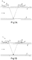
- FIG. 1 A, B the installation of two sensors on the outside of a pipe.
- a measuring unit 1 is positioned at a selected location of a pipe 2 of a pipeline network.
- a measuring unit 1 each of a first sensor 3 and a second sensor 4, which are in the illustrated embodiment along the tube axis side by side spaced mounted on the outside of the tube 2. Both sensors work either as transmitters or as receivers.
- the flow of water through the pipe 2 is determined by the ultrasonic measuring method.
- ultrasonic signals from the sensor 3 according to Fig. 1 A emitted, which are reflected on the opposite side of the tube and received by the second sensor 4 again. This first ultrasonic pulse is transmitted in the direction of flow, which is indicated by the arrow, through the liquid.
- a second ultrasonic pulse is sent against the flow direction of the second sensor 4 and detected by the first sensor 3 after reflection on the opposite pipe inner wall. Since the medium in which the ultrasound propagates flows, the transit time of the sound signals which flow through the medium in the direction of flow is shorter than the transit time of the signals which travel counter to the direction of flow. The transit time difference .DELTA.t is measured and allows the determination of the average flow velocity on the sound traversed path. By a profile correction, the surface mean of the flow rate can be calculated which is proportional to the volume flow.
- the distance between the sensors can be, for example, five centimeters.
- minimum and maximum flow limits can be set, which, if exceeded or undershot, automatically generate an alarm signal.
- the volumetric flows calculated in one of the measuring units are transmitted to a central computer unit with the aid of a GSM module.
- the measuring units can be assigned to a control cabinet, wherein at least the GSM module is located. Furthermore, in this cabinet, a PLC control unit (programmable logic controller) with digital input and output terminals and analog input terminal, a mode selector switch (on, off, commissioning), a power supply, a flow meter, a power connector, UPS (an uninterruptible power supply) and a Battery pack be accommodated for bridging voltage-free times.
- the power supply can also be provided by a solar panel (solar module, photovoltaic module or solar generator) or by night-time lighting through the street lighting. In the latter option, batteries are charged at night via a connection to a street lamp.
Landscapes
- Physics & Mathematics (AREA)
- General Physics & Mathematics (AREA)
- Electromagnetism (AREA)
- Fluid Mechanics (AREA)
- Examining Or Testing Airtightness (AREA)
- Arrangements For Transmission Of Measured Signals (AREA)
Claims (15)
- Procédé de surveillance et/ou de localisation de pertes d'eau dans un réseau de tuyauterie d'eau à plusieurs régimes hydrographiques, caractérisé par le fait que le procédé comprend au moins les étapes suivantes:- le positionnement d'unités de mesure sur des points sélectionnés du réseau de tuyauterie, dans lequel une unité de mesure (1) se compose respectivement de deux capteurs (3, 4) qui travaillent en même temps comme émetteur et comme récepteur et qui sont montés le long de l'axe de tuyau sur la face extérieure, de préférence au niveau de naissance, d'un tuyau (2),- la mesure de la vitesse d'écoulement du liquide dans le tuyau à l'aide d'un procédé de mesure par ultrasons dans lequel une première impulsion ultrasonore est émise à travers le liquide dans la direction d'écoulement ainsi qu'une deuxième impulsion ultrasonore est émise à l'encontre de la direction d'écoulement, les capteurs travaillent alternativement comme émetteur et comme récepteur, et la vitesse d'écoulement est déterminée à partir de la différence de temps de propagation Δt des signaux sonores dans la direction d'écoulement et des signaux sonores à l'encontre de la direction d'écoulement,- la transmission des données de mesure à une banque de données d'une unité informatique centrale à l'aide d'un module de transmission de données qui est connecté à l'unité de mesure respective, et,- l'évaluation des données de mesure dans l'unité informatique centrale en évaluant les données de mesure des régimes hydrographiques avec un minimum caractéristique, les régimes hydrographiques étant analysés quant à des valeurs minimales mesurées et les mouvements d'eau ainsi identifiés indiquant des pertes de fuite.
- Procédé selon la revendication 1, caractérisé par le fait que des informations sur l'état du réseau et/ou les modifications de celui-ci sont données et/ou une quantification des quantités de fuite est faite en comparant les données de mesure des unités de mesure individuelles et/ou des données en dérivées à des données de mesure relevées dans le passé.
- Procédé selon la revendication 2, caractérisé par le fait que la transmission des données de mesure depuis le module de transmission de données à une unité informatique centrale se fait via un réseau public de téléphonie mobile (GSM).
- Procédé selon la revendication 3, caractérisé par le fait que la position de l'endroit de fuite est délimitée localement à une zone partielle du réseau de tuyauterie en évaluant en commun des données de mesure d'unités de mesure voisines.
- Procédé selon la revendication 4, caractérisé par le fait que des unités de mesure sont mises en place dans le système de tuyauterie à une distance comprise entre 5 et 20 km.
- Procédé selon la revendication 5, caractérisé par le fait que la vitesse d'écoulement dans le tuyau est mesurée en permanence.
- Procédé selon la revendication 6, caractérisé par le fait que l'on détermine, à partir des données de mesure des unités de mesure, le débit de liquide qui s'est produit respectivement au minimum et au maximum ainsi qu'une valeur moyenne.
- Procédé selon la revendication 7, caractérisé par le fait que les débits volumiques sont calculés dans une unité informatique au niveau de l'unité de mesure et sont envoyés en tant que paquets de données comprimés munis d'un timbre horodateur, au format SMS, à l'unité informatique centrale.
- Procédé selon la revendication 8, caractérisé par le fait que l'ensemble des SMS de données est transmis à une centrale de réception ou que la collecte centrale et la préparation de données et/ou l'interrogation de résultats se font via une liaison internet.
- Procédé selon la revendication 9, caractérisé par le fait que, après l'indentification et la localisation grossière d'une perte de liquide à l'intérieur du réseau de tuyauterie, on procède, dans une deuxième étape, à une autre délimitation locale d'une fuite à l'aide d'une mesure plane du niveau de bruit dans la partie du réseau de tuyauterie qui s'est révélée être la zone potentielle de fuite.
- Procédé selon la revendication 10, caractérisé par le fait que, dans une troisième étape, la localisation de l'endroit de fuite dans la zone de réseau dans une large mesure délimitée est réalisée au moyen d'autres procédés de localisation de fuite, de préférence la corrélation.
- Programme informatique pour la mise en oeuvre d'un procédé selon l'une quelconque des revendications 1 à 11.
- Support de données comprenant un programme informatique selon la revendication 12.
- Système informatique sur lequel est chargé un programme informatique selon la revendication 12.
- Système de surveillance et/ou de localisation de pertes d'eau dans un réseau de tuyauterie d'eau à plusieurs régimes hydrographiques, caractérisé par le fait que le système comprend au moins les composants suivants:- une ou plusieurs unités de mesure (1) positionnées sur des points sélectionnés du réseau de tuyauterie, qui se composent chacune de deux capteurs (3, 4) qui travaillent en même temps comme émetteur et comme récepteur et qui sont montés le long de l'axe de tuyau sur la face extérieure, de préférence au niveau de naissance, d'un tuyau (2), et les unités de mesure sont aptes à mesurer la vitesse d'écoulement du liquide dans le tuyau à l'aide d'un procédé de mesure par ultrasons dans lequel une première impulsion ultrasonore est émise à travers le liquide dans la direction d'écoulement ainsi qu'une deuxième impulsion ultrasonore est émise à l'encontre de la direction d'écoulement, les capteurs travaillent alternativement comme émetteur et comme récepteur, et la vitesse d'écoulement est déterminée à partir de la différence de temps de propagation Δt des signaux sonores dans la direction d'écoulement et des signaux sonores à l'encontre de la direction d'écoulement,- un module de transmission de données qui est connecté à l'unité de mesure respective,- une banque de données qui est prévue dans une unité informatique centrale et à laquelle les données de mesure peuvent être transmises à l'aide dudit module de transmission de données, et- un module d'évaluation des données de mesure dans l'unité informatique centrale, les données de mesure des régimes hydrographiques étant évaluées avec un minimum caractéristique, les régimes hydrographiques étant analysés quant à des valeurs minimales mesurées et des mouvements d'eau ainsi identifiés indiquant des pertes de fuite.
Applications Claiming Priority (2)
| Application Number | Priority Date | Filing Date | Title |
|---|---|---|---|
| DE102008021929A DE102008021929B4 (de) | 2008-05-02 | 2008-05-02 | Verfahren zur Überwachung und/oder Ortung von Flüssigkeitsverlusten in einem Rohrleitungsnetz |
| EP09737909.3A EP2271907B1 (fr) | 2008-05-02 | 2009-01-16 | Procédé de contrôle et/ou de localisation de fuites de fluide dans un réseau de tuyauterie |
Related Parent Applications (1)
| Application Number | Title | Priority Date | Filing Date |
|---|---|---|---|
| EP09737909.3A Division EP2271907B1 (fr) | 2008-05-02 | 2009-01-16 | Procédé de contrôle et/ou de localisation de fuites de fluide dans un réseau de tuyauterie |
Publications (2)
| Publication Number | Publication Date |
|---|---|
| EP2913652A1 EP2913652A1 (fr) | 2015-09-02 |
| EP2913652B1 true EP2913652B1 (fr) | 2017-07-05 |
Family
ID=40875223
Family Applications (2)
| Application Number | Title | Priority Date | Filing Date |
|---|---|---|---|
| EP15163403.7A Not-in-force EP2913652B1 (fr) | 2008-05-02 | 2009-01-16 | Procédé de contrôle et/ou de localisation de fuites de fluide dans un réseau de tuyauterie |
| EP09737909.3A Not-in-force EP2271907B1 (fr) | 2008-05-02 | 2009-01-16 | Procédé de contrôle et/ou de localisation de fuites de fluide dans un réseau de tuyauterie |
Family Applications After (1)
| Application Number | Title | Priority Date | Filing Date |
|---|---|---|---|
| EP09737909.3A Not-in-force EP2271907B1 (fr) | 2008-05-02 | 2009-01-16 | Procédé de contrôle et/ou de localisation de fuites de fluide dans un réseau de tuyauterie |
Country Status (5)
| Country | Link |
|---|---|
| EP (2) | EP2913652B1 (fr) |
| DE (2) | DE202008017243U1 (fr) |
| ES (1) | ES2538732T3 (fr) |
| PL (1) | PL2271907T3 (fr) |
| WO (1) | WO2009132865A1 (fr) |
Families Citing this family (20)
| Publication number | Priority date | Publication date | Assignee | Title |
|---|---|---|---|---|
| DE202008017243U1 (de) * | 2008-05-02 | 2009-09-17 | Rbs Wave Gmbh | System zur Überwachung und/oder Ortung von Wasserverlusten in einem Wasserrohrleitungsnetz |
| US8850871B2 (en) | 2010-09-30 | 2014-10-07 | Siemens Aktiengesellschaft | Pipeline leak location using ultrasonic flowmeters |
| CN103822098A (zh) * | 2014-02-25 | 2014-05-28 | 上海肯特仪表股份有限公司 | 供水管网泄露监控方法 |
| GB2554950B (en) | 2016-10-17 | 2019-06-05 | Univ Cape Town | Pipe leak measurement and assessment |
| CN107061996B (zh) * | 2017-03-10 | 2019-04-16 | 内蒙古大学 | 一种供水管道泄漏检测定位方法 |
| CN109404745B (zh) * | 2018-12-18 | 2024-04-05 | 杨启敖 | 带超声波的漏水保护器 |
| CN109404744B (zh) * | 2018-12-18 | 2024-01-16 | 杨启敖 | 带前置过滤的漏水保护装置 |
| CN110906994A (zh) * | 2019-12-27 | 2020-03-24 | 苏州东剑智能科技有限公司 | 一种超声波水表及其智能检测漏水方法 |
| CN112464421B (zh) * | 2020-11-23 | 2022-07-05 | 长江水利委员会长江科学院 | 基于联合信息熵的供水管网漏损识别传感器优化布置方法 |
| CN112964302A (zh) * | 2021-02-10 | 2021-06-15 | 沈阳竞辰信息技术有限公司 | 一种液体管线运行状态实时监测方法 |
| CN113126100B (zh) * | 2021-03-16 | 2023-09-08 | 武汉中仪物联技术股份有限公司 | 一种管道探测器的导航方法及导航系统 |
| EP4083591B1 (fr) * | 2021-04-30 | 2025-04-16 | Kamstrup A/S | Procédé de détection acoustique de fuites dans un réseau de conduites de conduction thermique |
| CN114239194B (zh) * | 2021-10-20 | 2024-07-30 | 中州水务控股有限公司 | 一种大水量输供水管网漏损分析和漏点定位方法 |
| CN115899586B (zh) * | 2022-10-09 | 2025-11-28 | 中建三局绿色产业投资有限公司 | 一种分流制排水管网系统排查与检测方法 |
| CN116857572B (zh) * | 2023-07-14 | 2024-01-02 | 湖南理工学院 | 一种基于大数据的智慧水务管理方法及系统 |
| CN117330140B (zh) * | 2023-12-01 | 2024-03-08 | 山东省林业科学研究院 | 一种湿地水道流量的监测测量装置 |
| CN117588692B (zh) * | 2024-01-18 | 2024-03-22 | 成都秦川物联网科技股份有限公司 | 基于物联网的超声波流量计的泄漏检测方法、系统及设备 |
| CN118470054B (zh) * | 2024-04-28 | 2024-10-25 | 南京机电职业技术学院 | 基于路径优化算法的改进时差法测量仪流量监测方法 |
| CN118606876B (zh) * | 2024-08-08 | 2024-10-29 | 宁波东海集团有限公司 | 一种基于去噪后的夜间水量的漏损预警方法及系统 |
| CN120993974B (zh) * | 2025-10-24 | 2026-02-27 | 浙江沃国华阀门有限公司 | 一种闸阀定位控制系统及方法 |
Family Cites Families (10)
| Publication number | Priority date | Publication date | Assignee | Title |
|---|---|---|---|---|
| US3869915A (en) * | 1973-01-23 | 1975-03-11 | Joseph Baumoel | Digital flowmeter |
| DE2841674C2 (de) | 1978-09-25 | 1983-09-22 | Heide, Gerhard, Dipl.-Ing., 4006 Erkrath | Verfahren zur Überprüfung auf Leckverluste sowie dabei verwendbarer Meßschacht |
| US4930358A (en) * | 1987-03-27 | 1990-06-05 | Tokyo Keiki Co., Ltd. | Method of and apparatus for measuring flow velocity by using ultrasonic waves |
| GB2289760B (en) * | 1992-09-22 | 1997-10-08 | Joseph Baumoel | Method and apparatus for leak detection and pipeline temperature modelling method and apparatus |
| US5463905A (en) * | 1993-02-23 | 1995-11-07 | Baird; James D. | Portable non-invasive flowmeter for partially filled pipe |
| DE19528287C5 (de) * | 1995-08-02 | 2009-09-24 | Ingenieurgesellschaft F.A.S.T. für angewandte Sensortechnik mit beschränkter Haftung | Verfahren zur Erkennung eines Lecks in einem Trinkwasser-Versorgungsnetz und Anordnung zur Durchführung des Verfahrens |
| DE19701317A1 (de) * | 1997-01-16 | 1998-07-23 | Peter Dipl Ing Renner | Leckerkennung in Rohrleitungssystemen |
| DE19819258C2 (de) | 1998-04-29 | 2000-10-12 | Peter Martinek | Verfahren und Meßsonde zur Durchführung von Messungen in Wasserversorgungssystemen |
| DE10329909A1 (de) * | 2003-07-02 | 2005-01-20 | Abb Research Ltd. | System und Verfahren zur Bestimmung, Überwachung und Regulierung von Flüssigkeitsverlusten in Wasserversorgungsbetrieben oder Wasserversorgungsnetzen |
| DE202008017243U1 (de) * | 2008-05-02 | 2009-09-17 | Rbs Wave Gmbh | System zur Überwachung und/oder Ortung von Wasserverlusten in einem Wasserrohrleitungsnetz |
-
2008
- 2008-05-02 DE DE202008017243U patent/DE202008017243U1/de not_active Expired - Lifetime
- 2008-05-02 DE DE102008021929A patent/DE102008021929B4/de not_active Expired - Fee Related
-
2009
- 2009-01-16 PL PL09737909T patent/PL2271907T3/pl unknown
- 2009-01-16 EP EP15163403.7A patent/EP2913652B1/fr not_active Not-in-force
- 2009-01-16 ES ES09737909.3T patent/ES2538732T3/es active Active
- 2009-01-16 WO PCT/EP2009/050467 patent/WO2009132865A1/fr not_active Ceased
- 2009-01-16 EP EP09737909.3A patent/EP2271907B1/fr not_active Not-in-force
Also Published As
| Publication number | Publication date |
|---|---|
| DE202008017243U1 (de) | 2009-09-17 |
| PL2271907T3 (pl) | 2015-11-30 |
| WO2009132865A1 (fr) | 2009-11-05 |
| EP2271907A1 (fr) | 2011-01-12 |
| ES2538732T3 (es) | 2015-06-23 |
| EP2913652A1 (fr) | 2015-09-02 |
| EP2271907B1 (fr) | 2015-04-15 |
| DE102008021929B4 (de) | 2011-04-07 |
| DE102008021929A1 (de) | 2009-11-12 |
Similar Documents
| Publication | Publication Date | Title |
|---|---|---|
| EP2271907B1 (fr) | Procédé de contrôle et/ou de localisation de fuites de fluide dans un réseau de tuyauterie | |
| EP0009263B1 (fr) | Procédé de surveillance de fuites et puits de mesure utilisé à cet effet | |
| EP1828670B1 (fr) | Procede pour la determination assistee par ordinateur d'une duree de vie theoriquement restante d'une pile echangeable | |
| DE112012001851B4 (de) | Ermitteln von Fluid-Leckagevolumen in Pipelines | |
| DE102011003438B4 (de) | Einrichtung und Verfahren zur Ermittlung von Messwerten in einem strömenden Medium | |
| DE10254053B4 (de) | Verfahren und Vorrichtung zur Bestimmung und/oder Überwachung eines Volumen- und/oder Massenstroms | |
| WO2013000686A2 (fr) | Détection de fuites par bilan massique stochastique | |
| DE4420476B4 (de) | Verfahren und Vorrichtung zum Erfassen eines Lecks sowie zum Modellieren der Temperatur in einer Pipeline | |
| DE2263725C3 (de) | Anordnung zum Nachweisen von anomalen BetriebszustSnden in Rohrleitungen | |
| DE102005036508B4 (de) | Verfahren und Vorrichtung zur Überwachung und Detektierung von Beschichtungsdefekten einer erd- oder wasserverlegten Rohrleitung | |
| DE102010019086A1 (de) | Einrichtung sowie Verfahren zur Übertragung von Messsignalen in räumlich ausgedehnten Versorgungsnetzen | |
| DE2220539B2 (fr) | ||
| EP3612279B1 (fr) | Installation d'extinction d'incendie, système d'extinction d'incendie comportant cette dernière, ainsi que procédé pour la détermination de la propagation d'un feu | |
| EP3855147B1 (fr) | Compteur d'énergie et procédé de détermination d'une quantité de chaleur ou de froid | |
| CN103920329A (zh) | 一种工业流体管道过滤网堵塞过程仿真检测方法 | |
| EP3388811A1 (fr) | Dispositif et procédé de détection d'une fuite dans un système de conduite pour un fluide | |
| EP4283274B1 (fr) | Procédé de détection et/ou d'analyse d'une fuite dans une conduite de milieu liquide, notamment une conduite d'eau | |
| EP3875157A1 (fr) | Surveillance à distance d'un réseau des conduits au moyen de capteurs | |
| DD297706A5 (de) | Verfahren zur ueberpruefung des bestehens einer rohrleitungsverbindung zwischen zwei endpunkten | |
| DE102021133787A1 (de) | Detektion von Fremdkörpern in fließenden Messmedien | |
| EP4083591B1 (fr) | Procédé de détection acoustique de fuites dans un réseau de conduites de conduction thermique | |
| DE102005032132A1 (de) | Vorrichtung zur positionsabhängigen Detektion einer Leckage in einem verdeckten, von außen unzugänglichen Rohrleitungssystem | |
| EP4430364B1 (fr) | Procédé de fonctionnement d'un débitmètre à ultrasons et débitmètre à ultrasons | |
| DE102011082487A1 (de) | Verfahren und Sensoranordnung zum Messen des Drucks in einem Druckgefäß | |
| WO2025067778A1 (fr) | Procédé et dispositif de détection d'une fuite dans un réseau d'alimentation |
Legal Events
| Date | Code | Title | Description |
|---|---|---|---|
| PUAI | Public reference made under article 153(3) epc to a published international application that has entered the european phase |
Free format text: ORIGINAL CODE: 0009012 |
|
| AC | Divisional application: reference to earlier application |
Ref document number: 2271907 Country of ref document: EP Kind code of ref document: P |
|
| AK | Designated contracting states |
Kind code of ref document: A1 Designated state(s): AT BE BG CH CY CZ DE DK EE ES FI FR GB GR HR HU IE IS IT LI LT LU LV MC MK MT NL NO PL PT RO SE SI SK TR |
|
| 17P | Request for examination filed |
Effective date: 20151020 |
|
| RBV | Designated contracting states (corrected) |
Designated state(s): AT BE BG CH CY CZ DE DK EE ES FI FR GB GR HR HU IE IS IT LI LT LU LV MC MK MT NL NO PL PT RO SE SI SK TR |
|
| GRAP | Despatch of communication of intention to grant a patent |
Free format text: ORIGINAL CODE: EPIDOSNIGR1 |
|
| RIC1 | Information provided on ipc code assigned before grant |
Ipc: G01M 3/24 20060101AFI20161031BHEP Ipc: G01F 1/66 20060101ALI20161031BHEP |
|
| GRAJ | Information related to disapproval of communication of intention to grant by the applicant or resumption of examination proceedings by the epo deleted |
Free format text: ORIGINAL CODE: EPIDOSDIGR1 |
|
| INTG | Intention to grant announced |
Effective date: 20161207 |
|
| INTC | Intention to grant announced (deleted) | ||
| GRAP | Despatch of communication of intention to grant a patent |
Free format text: ORIGINAL CODE: EPIDOSNIGR1 |
|
| INTG | Intention to grant announced |
Effective date: 20170201 |
|
| GRAS | Grant fee paid |
Free format text: ORIGINAL CODE: EPIDOSNIGR3 |
|
| GRAA | (expected) grant |
Free format text: ORIGINAL CODE: 0009210 |
|
| AC | Divisional application: reference to earlier application |
Ref document number: 2271907 Country of ref document: EP Kind code of ref document: P |
|
| AK | Designated contracting states |
Kind code of ref document: B1 Designated state(s): AT BE BG CH CY CZ DE DK EE ES FI FR GB GR HR HU IE IS IT LI LT LU LV MC MK MT NL NO PL PT RO SE SI SK TR |
|
| REG | Reference to a national code |
Ref country code: GB Ref legal event code: FG4D Free format text: NOT ENGLISH |
|
| REG | Reference to a national code |
Ref country code: CH Ref legal event code: EP |
|
| REG | Reference to a national code |
Ref country code: AT Ref legal event code: REF Ref document number: 906930 Country of ref document: AT Kind code of ref document: T Effective date: 20170715 |
|
| REG | Reference to a national code |
Ref country code: IE Ref legal event code: FG4D Free format text: LANGUAGE OF EP DOCUMENT: GERMAN |
|
| REG | Reference to a national code |
Ref country code: DE Ref legal event code: R096 Ref document number: 502009014133 Country of ref document: DE |
|
| REG | Reference to a national code |
Ref country code: NL Ref legal event code: MP Effective date: 20170705 |
|
| REG | Reference to a national code |
Ref country code: LT Ref legal event code: MG4D |
|
| PG25 | Lapsed in a contracting state [announced via postgrant information from national office to epo] |
Ref country code: NL Free format text: LAPSE BECAUSE OF FAILURE TO SUBMIT A TRANSLATION OF THE DESCRIPTION OR TO PAY THE FEE WITHIN THE PRESCRIBED TIME-LIMIT Effective date: 20170705 Ref country code: NO Free format text: LAPSE BECAUSE OF FAILURE TO SUBMIT A TRANSLATION OF THE DESCRIPTION OR TO PAY THE FEE WITHIN THE PRESCRIBED TIME-LIMIT Effective date: 20171005 Ref country code: HR Free format text: LAPSE BECAUSE OF FAILURE TO SUBMIT A TRANSLATION OF THE DESCRIPTION OR TO PAY THE FEE WITHIN THE PRESCRIBED TIME-LIMIT Effective date: 20170705 Ref country code: FI Free format text: LAPSE BECAUSE OF FAILURE TO SUBMIT A TRANSLATION OF THE DESCRIPTION OR TO PAY THE FEE WITHIN THE PRESCRIBED TIME-LIMIT Effective date: 20170705 Ref country code: LT Free format text: LAPSE BECAUSE OF FAILURE TO SUBMIT A TRANSLATION OF THE DESCRIPTION OR TO PAY THE FEE WITHIN THE PRESCRIBED TIME-LIMIT Effective date: 20170705 Ref country code: SE Free format text: LAPSE BECAUSE OF FAILURE TO SUBMIT A TRANSLATION OF THE DESCRIPTION OR TO PAY THE FEE WITHIN THE PRESCRIBED TIME-LIMIT Effective date: 20170705 |
|
| PG25 | Lapsed in a contracting state [announced via postgrant information from national office to epo] |
Ref country code: IS Free format text: LAPSE BECAUSE OF FAILURE TO SUBMIT A TRANSLATION OF THE DESCRIPTION OR TO PAY THE FEE WITHIN THE PRESCRIBED TIME-LIMIT Effective date: 20171105 Ref country code: LV Free format text: LAPSE BECAUSE OF FAILURE TO SUBMIT A TRANSLATION OF THE DESCRIPTION OR TO PAY THE FEE WITHIN THE PRESCRIBED TIME-LIMIT Effective date: 20170705 Ref country code: GR Free format text: LAPSE BECAUSE OF FAILURE TO SUBMIT A TRANSLATION OF THE DESCRIPTION OR TO PAY THE FEE WITHIN THE PRESCRIBED TIME-LIMIT Effective date: 20171006 Ref country code: BG Free format text: LAPSE BECAUSE OF FAILURE TO SUBMIT A TRANSLATION OF THE DESCRIPTION OR TO PAY THE FEE WITHIN THE PRESCRIBED TIME-LIMIT Effective date: 20171005 Ref country code: PL Free format text: LAPSE BECAUSE OF FAILURE TO SUBMIT A TRANSLATION OF THE DESCRIPTION OR TO PAY THE FEE WITHIN THE PRESCRIBED TIME-LIMIT Effective date: 20170705 Ref country code: ES Free format text: LAPSE BECAUSE OF FAILURE TO SUBMIT A TRANSLATION OF THE DESCRIPTION OR TO PAY THE FEE WITHIN THE PRESCRIBED TIME-LIMIT Effective date: 20170705 |
|
| REG | Reference to a national code |
Ref country code: DE Ref legal event code: R097 Ref document number: 502009014133 Country of ref document: DE |
|
| PG25 | Lapsed in a contracting state [announced via postgrant information from national office to epo] |
Ref country code: DK Free format text: LAPSE BECAUSE OF FAILURE TO SUBMIT A TRANSLATION OF THE DESCRIPTION OR TO PAY THE FEE WITHIN THE PRESCRIBED TIME-LIMIT Effective date: 20170705 Ref country code: CZ Free format text: LAPSE BECAUSE OF FAILURE TO SUBMIT A TRANSLATION OF THE DESCRIPTION OR TO PAY THE FEE WITHIN THE PRESCRIBED TIME-LIMIT Effective date: 20170705 Ref country code: RO Free format text: LAPSE BECAUSE OF FAILURE TO SUBMIT A TRANSLATION OF THE DESCRIPTION OR TO PAY THE FEE WITHIN THE PRESCRIBED TIME-LIMIT Effective date: 20170705 |
|
| PLBE | No opposition filed within time limit |
Free format text: ORIGINAL CODE: 0009261 |
|
| STAA | Information on the status of an ep patent application or granted ep patent |
Free format text: STATUS: NO OPPOSITION FILED WITHIN TIME LIMIT |
|
| PG25 | Lapsed in a contracting state [announced via postgrant information from national office to epo] |
Ref country code: SK Free format text: LAPSE BECAUSE OF FAILURE TO SUBMIT A TRANSLATION OF THE DESCRIPTION OR TO PAY THE FEE WITHIN THE PRESCRIBED TIME-LIMIT Effective date: 20170705 Ref country code: IT Free format text: LAPSE BECAUSE OF FAILURE TO SUBMIT A TRANSLATION OF THE DESCRIPTION OR TO PAY THE FEE WITHIN THE PRESCRIBED TIME-LIMIT Effective date: 20170705 Ref country code: EE Free format text: LAPSE BECAUSE OF FAILURE TO SUBMIT A TRANSLATION OF THE DESCRIPTION OR TO PAY THE FEE WITHIN THE PRESCRIBED TIME-LIMIT Effective date: 20170705 |
|
| 26N | No opposition filed |
Effective date: 20180406 |
|
| PG25 | Lapsed in a contracting state [announced via postgrant information from national office to epo] |
Ref country code: SI Free format text: LAPSE BECAUSE OF FAILURE TO SUBMIT A TRANSLATION OF THE DESCRIPTION OR TO PAY THE FEE WITHIN THE PRESCRIBED TIME-LIMIT Effective date: 20170705 |
|
| REG | Reference to a national code |
Ref country code: CH Ref legal event code: PL |
|
| GBPC | Gb: european patent ceased through non-payment of renewal fee |
Effective date: 20180116 |
|
| PG25 | Lapsed in a contracting state [announced via postgrant information from national office to epo] |
Ref country code: MT Free format text: LAPSE BECAUSE OF FAILURE TO SUBMIT A TRANSLATION OF THE DESCRIPTION OR TO PAY THE FEE WITHIN THE PRESCRIBED TIME-LIMIT Effective date: 20170705 |
|
| PG25 | Lapsed in a contracting state [announced via postgrant information from national office to epo] |
Ref country code: FR Free format text: LAPSE BECAUSE OF NON-PAYMENT OF DUE FEES Effective date: 20180131 Ref country code: LU Free format text: LAPSE BECAUSE OF NON-PAYMENT OF DUE FEES Effective date: 20180116 |
|
| REG | Reference to a national code |
Ref country code: IE Ref legal event code: MM4A |
|
| REG | Reference to a national code |
Ref country code: FR Ref legal event code: ST Effective date: 20180928 |
|
| REG | Reference to a national code |
Ref country code: BE Ref legal event code: MM Effective date: 20180131 |
|
| PG25 | Lapsed in a contracting state [announced via postgrant information from national office to epo] |
Ref country code: LI Free format text: LAPSE BECAUSE OF NON-PAYMENT OF DUE FEES Effective date: 20180131 Ref country code: CH Free format text: LAPSE BECAUSE OF NON-PAYMENT OF DUE FEES Effective date: 20180131 Ref country code: GB Free format text: LAPSE BECAUSE OF NON-PAYMENT OF DUE FEES Effective date: 20180116 Ref country code: BE Free format text: LAPSE BECAUSE OF NON-PAYMENT OF DUE FEES Effective date: 20180131 |
|
| PG25 | Lapsed in a contracting state [announced via postgrant information from national office to epo] |
Ref country code: IE Free format text: LAPSE BECAUSE OF NON-PAYMENT OF DUE FEES Effective date: 20180116 |
|
| REG | Reference to a national code |
Ref country code: AT Ref legal event code: MM01 Ref document number: 906930 Country of ref document: AT Kind code of ref document: T Effective date: 20180116 |
|
| PG25 | Lapsed in a contracting state [announced via postgrant information from national office to epo] |
Ref country code: AT Free format text: LAPSE BECAUSE OF NON-PAYMENT OF DUE FEES Effective date: 20180116 |
|
| PG25 | Lapsed in a contracting state [announced via postgrant information from national office to epo] |
Ref country code: MC Free format text: LAPSE BECAUSE OF FAILURE TO SUBMIT A TRANSLATION OF THE DESCRIPTION OR TO PAY THE FEE WITHIN THE PRESCRIBED TIME-LIMIT Effective date: 20170705 |
|
| PG25 | Lapsed in a contracting state [announced via postgrant information from national office to epo] |
Ref country code: TR Free format text: LAPSE BECAUSE OF FAILURE TO SUBMIT A TRANSLATION OF THE DESCRIPTION OR TO PAY THE FEE WITHIN THE PRESCRIBED TIME-LIMIT Effective date: 20170705 |
|
| PGFP | Annual fee paid to national office [announced via postgrant information from national office to epo] |
Ref country code: DE Payment date: 20200311 Year of fee payment: 12 |
|
| PG25 | Lapsed in a contracting state [announced via postgrant information from national office to epo] |
Ref country code: PT Free format text: LAPSE BECAUSE OF FAILURE TO SUBMIT A TRANSLATION OF THE DESCRIPTION OR TO PAY THE FEE WITHIN THE PRESCRIBED TIME-LIMIT Effective date: 20170705 |
|
| PG25 | Lapsed in a contracting state [announced via postgrant information from national office to epo] |
Ref country code: MK Free format text: LAPSE BECAUSE OF NON-PAYMENT OF DUE FEES Effective date: 20170705 Ref country code: CY Free format text: LAPSE BECAUSE OF FAILURE TO SUBMIT A TRANSLATION OF THE DESCRIPTION OR TO PAY THE FEE WITHIN THE PRESCRIBED TIME-LIMIT Effective date: 20170705 Ref country code: HU Free format text: LAPSE BECAUSE OF FAILURE TO SUBMIT A TRANSLATION OF THE DESCRIPTION OR TO PAY THE FEE WITHIN THE PRESCRIBED TIME-LIMIT; INVALID AB INITIO Effective date: 20090116 |
|
| REG | Reference to a national code |
Ref country code: DE Ref legal event code: R119 Ref document number: 502009014133 Country of ref document: DE |
|
| PG25 | Lapsed in a contracting state [announced via postgrant information from national office to epo] |
Ref country code: DE Free format text: LAPSE BECAUSE OF NON-PAYMENT OF DUE FEES Effective date: 20210803 |