EP2913686B1 - Lasttester - Google Patents
Lasttester Download PDFInfo
- Publication number
- EP2913686B1 EP2913686B1 EP14863074.2A EP14863074A EP2913686B1 EP 2913686 B1 EP2913686 B1 EP 2913686B1 EP 14863074 A EP14863074 A EP 14863074A EP 2913686 B1 EP2913686 B1 EP 2913686B1
- Authority
- EP
- European Patent Office
- Prior art keywords
- resistor
- power source
- exhaust
- testing apparatus
- detection part
- Prior art date
- Legal status (The legal status is an assumption and is not a legal conclusion. Google has not performed a legal analysis and makes no representation as to the accuracy of the status listed.)
- Active
Links
Images




Classifications
-
- G—PHYSICS
- G01—MEASURING; TESTING
- G01R—MEASURING ELECTRIC VARIABLES; MEASURING MAGNETIC VARIABLES
- G01R19/00—Arrangements for measuring currents or voltages or for indicating presence or sign thereof
- G01R19/165—Indicating that current or voltage is either above or below a predetermined value or within or outside a predetermined range of values
-
- G—PHYSICS
- G01—MEASURING; TESTING
- G01R—MEASURING ELECTRIC VARIABLES; MEASURING MAGNETIC VARIABLES
- G01R31/00—Arrangements for testing electric properties; Arrangements for locating electric faults; Arrangements for electrical testing characterised by what is being tested not provided for elsewhere
- G01R31/34—Testing dynamo-electric machines
- G01R31/343—Testing dynamo-electric machines in operation
-
- G—PHYSICS
- G01—MEASURING; TESTING
- G01R—MEASURING ELECTRIC VARIABLES; MEASURING MAGNETIC VARIABLES
- G01R19/00—Arrangements for measuring currents or voltages or for indicating presence or sign thereof
- G01R19/145—Indicating the presence of current or voltage
- G01R19/15—Indicating the presence of current
-
- G—PHYSICS
- G01—MEASURING; TESTING
- G01R—MEASURING ELECTRIC VARIABLES; MEASURING MAGNETIC VARIABLES
- G01R19/00—Arrangements for measuring currents or voltages or for indicating presence or sign thereof
- G01R19/145—Indicating the presence of current or voltage
- G01R19/155—Indicating the presence of voltage
-
- G—PHYSICS
- G01—MEASURING; TESTING
- G01R—MEASURING ELECTRIC VARIABLES; MEASURING MAGNETIC VARIABLES
- G01R31/00—Arrangements for testing electric properties; Arrangements for locating electric faults; Arrangements for electrical testing characterised by what is being tested not provided for elsewhere
- G01R31/40—Testing power supplies
-
- G—PHYSICS
- G01—MEASURING; TESTING
- G01R—MEASURING ELECTRIC VARIABLES; MEASURING MAGNETIC VARIABLES
- G01R31/00—Arrangements for testing electric properties; Arrangements for locating electric faults; Arrangements for electrical testing characterised by what is being tested not provided for elsewhere
- G01R31/40—Testing power supplies
- G01R31/42—AC power supplies
-
- G—PHYSICS
- G01—MEASURING; TESTING
- G01R—MEASURING ELECTRIC VARIABLES; MEASURING MAGNETIC VARIABLES
- G01R1/00—Details of instruments or arrangements of the types included in groups G01R5/00 - G01R13/00 and G01R31/00
- G01R1/20—Modifications of basic electric elements for use in electric measuring instruments; Structural combinations of such elements with such instruments
- G01R1/203—Resistors used for electric measuring, e.g. decade resistors standards, resistors for comparators, series resistors, shunts
Definitions
- the present invention relates to a load testing apparatus.
- Patent Literature 1 an apparatus that stops energization to a resistor in a case where a current flowing through the resistor or the like is abnormal in a load test has been proposed.
- abnormality detection of the load testing apparatus including various units, such as a cooling fan cannot be appropriately performed only by detecting the current flowing through the resistor or the like.
- an object of the present invention is to provide a load testing apparatus capable of appropriately performing abnormality detection therein, as defined in claim 1.
- a load testing apparatus includes: a resistive unit that includes one or more resistor groups having a plurality of resistors and is connected with a power source to be tested for a load test; a cooling fan that cools the resistors in the resistive unit; and a control unit, wherein the resistive unit is provided with a current/voltage detection part that detects a current flowing through or a voltage applied to the resistors, the resistor groups, or the resistive unit and a temperature detection part that detects an exhaust temperature at a downstream of the resistive unit, a rotation state detection part that detects a rotation state of the cooling fan is provided in the cooling fan, and the control unit performs off control that stops power supply from the power source to be tested to the resistive unit based on information from the current/voltage detection part, information from the temperature detection part, and information from the rotation state detection part.
- the control unit performs the off control after detecting the operating condition of the cooling fan by the rotation state detection part, the condition of the current or the voltage by the current/voltage detection part, and the exhaust temperature by the temperature detection part. Accordingly, in a case where a malfunction has occurred in the load testing apparatus, the control unit stops the power supply from the power source to be tested to the load testing apparatus (the resistive unit). As a result, abnormality detection inside the load testing apparatus is appropriately performed, and a further failure of the load testing apparatus (particularly, the resistive unit) can be prevented.
- the load testing apparatus further includes: a current/voltage warning part indicating by at least one of light and sound that the off control is based on the information from the current/voltage detection part; a temperature warning part indicating by at least one of light and sound that the off control is based on the information from the temperature detection part; and a cooling fan warning part indicating by at least one of light and sound that the off control is based on the information from the rotation state detection part.
- a current/voltage warning part indicating by at least one of light and sound that the off control is based on the information from the current/voltage detection part
- a temperature warning part indicating by at least one of light and sound that the off control is based on the information from the temperature detection part
- a cooling fan warning part indicating by at least one of light and sound that the off control is based on the information from the rotation state detection part.
- the warning to indicate the malfunctioning place it is possible to grasp whether it is an operation failure of the cooling fan, a malfunction of the resistive unit, the other malfunction (or an overall malfunction), or the like, and the malfunction can be easily improved.
- the resistive unit has the two or more resistor groups, the resistor group includes two or more selection switches that are used for selecting whether or not the power from the power source to be tested is supplied, the current/voltage detection part is provided for every resistor group, and as the current/voltage warning part, a lighting device is provided in a vicinity of each of the two or more selection switches.
- the warning to indicate the malfunctioning place it is possible to visually recognize whether it is an operation failure of the cooling fan, a malfunction of the resistive unit (and which resistor group has the malfunction), the other malfunction (or an overall malfunction), or the like, and the malfunction can be easily improved.
- an exhaust lid that opens when being used is provided at an exhaust port at the downstream of the resistive unit
- an exhaust opening detection part that detects an opened/closed state of the exhaust lid is provided at the exhaust port or the exhaust lid
- the control unit performs the off control based on the information from the current/voltage detection part, the information from the temperature detection part, the information from the rotation state detection part, and information from the exhaust opening detection part.
- an intake lid that opens when being used is provided at an intake port of the cooling fan
- an intake opening detection part that detects an opened/closed state of the intake lid is provided at the intake port or the intake lid
- the control unit performs the off control based on the information from the current/voltage detection part, the information from the temperature detection part, the information from the rotation state detection part, the information from the exhaust opening detection part, and information from the intake opening detection part.
- an opening operation of the exhaust lid is performed by driving an actuator, the off control is started after a time needed to open the exhaust lid by the actuator has passed since a main power source of the load testing apparatus is turned on.
- a load testing apparatus includes: a resistive unit that includes one or more resistor groups having a plurality of resistors and is connected with a power source to be tested for a load test; a cooling fan that cools the resistors in the resistive unit; and a control unit, wherein an exhaust lid that opens when being used is provided at an exhaust port at a downstream of the resistive unit, an exhaust opening detection part that detects an opened/closed state of the exhaust lid is provided at the exhaust port or the exhaust lid, and the control unit performs off control that stops power supply from the power source to be tested to the resistive unit based on information from the exhaust opening detection part and at least one of information about a current flowing through or a voltage applied to the resistors, the resistor groups, or the resistive unit, information about an exhaust temperature at the downstream of the resistive unit, and information about a rotation state of the cooling fan.
- the load testing apparatus further includes a protective relay that performs the off control based on information about a current flowing through a power source line from a power source for driving that supplies power driving the cooling fan or a voltage applied from the power source for driving to the load testing apparatus via the power source line.
- a protective relay that performs the off control based on information about a current flowing through a power source line from a power source for driving that supplies power driving the cooling fan or a voltage applied from the power source for driving to the load testing apparatus via the power source line.
- Abnormality detection of a power supply source is performed based on a power supply state from the auxiliary power source serving as a source of driving the respective units of the load testing apparatus.
- the power supply from the auxiliary power source is performed normally, the power supply from the power source to be tested is enabled. Accordingly, it is possible to perform the abnormality detection or the load test of the load testing apparatus correctly.
- the load testing apparatus capable of appropriately performing the abnormality detection therein can be provided.
- a load testing apparatus 1 in a first embodiment includes a cooling fan 10, a resistive unit 20, a housing 30, a main switch 50, an operation unit 60, and a control unit 80, and is used for performing a load test of a power source device (power source to be tested), such as a generator (see Figs. 1 to 6 ).
- a power source device power source to be tested
- a generator see Figs. 1 to 6 .
- the cooling fan 10 is a device that feeds cooling air to the resistive unit 20, and the resistive unit 20 is disposed above the cooling fan 10.
- a rotation state detection part 10a such as a fiber sensor, a laser sensor, a photoelectric sensor, or a wind pressure sensor, that detects a rotation state of a fan is provided in the cooling fan 10.
- the rotation state detection part 10a detects a rotation number of the cooling fan 10 and transmits information about the rotation number to the control unit 80.
- the resistive unit 20 is a unit provided with one or more resistor groups where a plurality of bar-shaped resistors extending in a horizontal direction is aligned with a predetermined interval therebetween and is connected in series or in parallel. During the load test, power from the power source to be tested is supplied to a portion or the whole of the resistor groups.
- the resistor is not limited to a resistor constituted by an electrical heating wire and may be a resistor, such as a battery, that is capable of accumulating power inside.
- the resistive unit 20 is provided with a current/voltage detection part 20a that detects a current flowing through the resistor or a voltage applied to the resistor by connecting with a bus bar or an electric cable connected to the resistor, such as an ammeter or a voltmeter, and a temperature detection part 20b that detects an exhaust temperature of an upper portion of the resistive unit 20.
- a current/voltage detection part 20a that detects a current flowing through the resistor or a voltage applied to the resistor by connecting with a bus bar or an electric cable connected to the resistor, such as an ammeter or a voltmeter
- a temperature detection part 20b that detects an exhaust temperature of an upper portion of the resistive unit 20.
- the current/voltage detection part 20a detects the current flowing through the resistor or the voltage applied to the resistor and transmits information about the current or the voltage to the control unit 80. It is desirable that the current/voltage detection part 20a be in a form of being disposed at every resistor group. However, it is possible to be in a form where the only one current/voltage detection part 20a is disposed at a portion of a previous stage where the power supplied from the power source to be tested via the main switch 50 is distributed to each resistor group. Further, it is possible to be in a form where the current/voltage detection part 20a is disposed at each and every resistor configuring the resistor group.
- the present embodiment gives an example where the current/voltage detection part 20a is disposed at every resistor group. Since switches (a first switch S1 to a fourth switch S4) of a selection switch 60b are provided only by the number of the resistor groups (four in the present embodiment), there is a merit that the resistor group having a malfunctioning place is easily indicated.
- the power source to be tested is a three-phase AC power source
- each of the only three current/voltage detection parts 20a is disposed at every U-phase, V-phase, and W-phase at a portion of the previous stage where the power supplied from the power source to be tested via the main switch 50 is distributed at every resistor group.
- the present embodiment gives an example where a total of four resistor groups consisting of two resistor groups (a first resistor group G1, a second resistor group G2) with a rated capacity of 5 kW and two resistor groups (a third resistor group G3, a fourth resistor group G4) with a rated capacity of 10 kW are provided for a load test of the three-phase AC power source.
- Each resistor group is provided with two resistors (a first resistor R 1 , a second resistor R 2 ) connected in series for the U-phase that connects with an R-phase terminal of the power source to be tested, two resistors (a third resistor R 3 , a fourth resistor R 4 ) connected in series for the V-phase that connects with an S-phase terminal of the power source to be tested, two resistors (a fifth resistor R 5 , a sixth resistor R 6 ) connected in series for the W-phase that connects with a T-phase terminal of the power source to be tested, and a switching device (a relay) SW between the first resistor R 1 and second resistor R 2 , between the third resistor R 3 and the fourth resistor R 4 , and between the fifth resistor R 5 and the sixth resistor R 6 .
- a switching device a relay
- the switching device SW is on/off controlled corresponding to on/off operation of the first switch S1 to the fourth switch S4, which will be described below, and causes the current to flow through the corresponding resistor in an on state.
- the switching device SW may be a triple-unit switch where a relay for the U-phase, a relay for the V-phase, and a relay for the W-phase on/off operate by linking with each other, or may be a single-unit switch where the respective relays on/off operate independently.
- One terminal of the second resistor R 2 in each resistor group is connected with a line UB for the U-phase that extends from a U-phase terminal U 1 that connects with the R-phase terminal of the power source to be tested, one terminal of the fourth resistor R 4 therein is connected with a line VB for the V-phase that extends from a V-phase terminal V 1 that connects with the S-phase terminal of the power source to be tested, and one terminal of the sixth resistor R 6 therein is connected with a line WB for the W-phase that extends from a W-phase terminal W 1 that connects with the T-phase terminal of the power source to be tested.
- One terminal of the first resistor R 1 in each resistor group, one terminal of the third resistor R 3 therein, and one terminal of the fifth resistor R 5 therein are short-circuited.
- the number of the resistor groups, the rated voltages or the rated capacities thereof, the wiring of the resistors, and the switching devices SW are not limited to the aforementioned configuration.
- a form where an ammeter for the U-phase is provided at a portion of the switching device SW in each resistor group that connects with the first resistor R 1 , an ammeter for the V-phase is provided at a portion thereof that connects with the third resistor R 3 , and an ammeter for the W-phase is provided at a portion thereof that connects with the fifth resistor R 5 is considered as an installation example of the current/voltage detection part 20a.
- a form where a voltmeter whose ends are connected to one terminal of the first resistor R 1 and one terminal of the second resistor R 2 in each resistor group is provided, a voltmeter whose ends are connected to one terminal of the third resistor R 3 and one terminal of the fourth resistor R 4 therein is provided, and a voltmeter whose ends are connected to one terminal of the fifth resistor R 5 and one terminal of the sixth resistor R 6 therein is provided is considered as an installation example of the current/voltage detection part 20a.
- the number of the resistor groups, the rated voltages or the rated capacities thereof, the wiring of the resistors, and the arrangements of the ammeters or the voltmeters are not limited to the aforementioned configuration.
- the current/voltage detection part 20a may be in a form of detecting at least one of the current and the voltage. However, in order to accurately detect an abnormality, it is desirable that the current/voltage detection part 20a be in a form of detecting both the current and the voltage.
- the temperature detection part 20b detects the exhaust temperature of the upper part (downstream) of the resistive unit 20 and transmits information about the exhaust temperature to the control unit 80.
- the housing 30 is a case that holds the load testing apparatus, such as the cooling fan 10, the resistive unit 20, the main switch 50, the operation unit 60, and the control unit 80.
- the load testing apparatus such as the cooling fan 10, the resistive unit 20, the main switch 50, the operation unit 60, and the control unit 80.
- an intake port 31 is provided on a lower side surface (upstream) of the cooling fan 10
- an exhaust port 33 is provided on an upper side (downstream) of the resistive unit 20.
- An intake lid 32 that is opened when being used and closed when not being used is provided at the intake port 31, and an exhaust lid 34 that is opened when being used and closed when not being used is provided at the exhaust port 33.
- the intake lid 32 is opened and closed via a first actuator 32a that operates by linking with on/off operation of the operation unit 60.
- the intake lid 32 is provided with an intake opening detection part 32b that is structured by a proximity sensor, a limit switch, or the like.
- the intake opening detection part 32b detects an opened/closed state of the intake lid 32, i.e., whether the intake port 31 is opened. It should be noted that the opening/closing is not limited to automatic opening/closing using the first actuator 32a and may be in a form of manually opening and closing the intake lid 32.
- the intake opening detection part 32b detects whether or not the intake lid 32 is opened and transmits information about whether or not the intake lid 32 is opened to the control unit 80.
- the intake opening detection part 32b may have a form of detecting a degree of opening/closing of the intake lid 32 further minutely.
- the exhaust lid 34 is opened and closed via a second actuator 34a that operates by linking with the on/off operation of the operation unit 60.
- the exhaust lid 34 is provided with an exhaust opening detection part 34b that is structured by a proximity sensor, a limit switch, or the like.
- the exhaust opening detection part 34b detects an opened/closed state of the exhaust lid 34, i.e., whether the exhaust port 33 is opened. It should be noted that the opening/closing is not limited to automatic opening/closing using the second actuator 34a and may be in a form of manually opening and closing the exhaust lid 34.
- the exhaust opening detection part 34b detects whether or not the exhaust lid 34 is opened and transmits information about whether or not the exhaust lid 34 is opened to the control unit 80.
- the exhaust opening detection part 34b may have a form of detecting a degree of opening/closing of the exhaust lid 34 further minutely.
- any of the intake lid 32 and the exhaust lid 34 is configured by a hinged door via a hinge.
- the intake lid 32 or the exhaust lid 34 may be in a form of being configured by the other door structure, such as a sliding door.
- the main switch 50 is constituted by a VCB (Vacuum Circuit Breaker) and the like, and is connected between the resistive unit 20 and the power source to be tested (provided on the line UB for the U-phase, on the line VB for the V-phase, and on the line WB for the W-phase).
- the power from the power source to be tested is supplied to the resistive unit 20 in an on state, and the power supply from the power source to be tested to the resistive unit 20 is stopped in an off state.
- the main switch 50 While the load testing apparatus 1 operates normally, the main switch 50 is in the on state. In a case where the control unit 80 determines that any of the members configuring the load testing apparatus 1 is not operated normally (in a case where an abnormality is detected) based on the information from the respective detection parts, the main switch 50 is turned off, i.e., off control that stops the power supply from the power source to be tested to the resistive unit 20 is performed.
- the operation unit 60 is provided with an on/off operation switch 60a that turns on or off a power source of the load testing apparatus 1 and the selection switch 60b (the first switch S1 to the fourth switch S4) that adjusts a load amount (selects the resistor group where the power supply from the power source to be tested is performed).
- the on/off operation switch 60a When the on/off operation switch 60a is operated and the main power source of the load testing apparatus 1 is turned on, based on power supplied from a power source for driving the load testing apparatus (auxiliary power source), the first actuator 32a operates to open the intake lid 32, and the second actuator 34a operates to open the exhaust lid 34.
- the fan in the cooling fan 10 is rotated to feed air taken in from an opening part of the intake lid 32 to the resistive unit 20 disposed above.
- the control unit 80, the rotation state detection part 10a, the current/voltage detection part 20a, the temperature detection part 20b, the intake opening detection part 32b, and the exhaust opening detection part 34b operate.
- an on/off switch for the cooling fan 10 is provided separately from the on/off operation switch 60a, the on/off operation switch 60a is operated, and in a state in which the main power source of the load testing apparatus 1 is turned on, the on/off switch for the cooling fan 10 is operated to start rotation of the fan in the cooling fan 10.
- the selection switch 60b (the first switch S1 to the fourth switch S4) is operated to enable energization to the resistive unit 20.
- the main switch 50 is turned on, the switching device SW of the resistor group corresponding to the selection switch 60b (the first switch S1 or the like) that has selected the energization is turned on, and the power is supplied from the power source to be tested connected via the main switch 50 to the resistor group that can be energized in the resistive unit 20.
- the switching devices SW of the first resistor group G1 and the second resistor group G2 with the rated capacity of 5 kW corresponding to the first switch S1 and the second switch S2 are turned on, and the power from the power source to be tested is supplied to the first resistor group G1 and the second resistor group G2.
- the switching devices SW of the third resistor group G3 and the fourth resistor group G4 with the rated capacity of 10 kW corresponding to the third switch S3 and the fourth switch S4 are turned off, and the power from the power source to be tested is not supplied to the third resistor group G3 and the fourth resistor group G4.
- the operation unit 60 is provided with an intake lid warning part 61a, an exhaust lid warning part 61b, a cooling fan warning part 61c, a current/voltage warning part 61d, and a temperature warning part 61e.
- the intake lid warning part 61a, the exhaust lid warning part 61b, the cooling fan warning part 61c, the current/voltage warning part 61d, or the temperature warning part 61e performs an output for warning, according to a malfunction of a state of the member corresponding to the intake lid warning part 61a, the exhaust lid warning part 61b, the cooling fan warning part 61c, the current/voltage warning part 61d, or the temperature warning part 61e.
- the intake lid warning part 61a is provided in a vicinity of an "Intake lid” column provided in the operation unit 60. In a case where the intake lid 32 is not sufficiently opened, the intake lid warning part 61a lights for warning to indicate by light that off control is based on the information from the intake opening detection part 32b.
- the exhaust lid warning part 61b is provided in a vicinity of an "Exhaust lid” column provided in the operation unit 60. In a case where the exhaust lid 34 is not sufficiently opened, the exhaust lid warning part 61b lights for warning to indicate by light that off control is based on the information from the exhaust opening detection part 34b.
- the cooling fan warning part 61c is provided in a vicinity of a "Cooling fan" column provided in the operation unit 60. In a case where the cooling fan 10 does not operate normally, the cooling fan warning part 61c lights for warning to indicate by light that off control is based on the information from the rotation state detection part 10a.
- the first warning part 61d1 to the fourth warning part 61d4 included in the current/voltage warning part 61d are respectively provided in vicinities of the first switch S1 to the fourth switch S4.
- any of the first warning part 61d1 to the fourth warning part 61d4 lights for warning to indicate by light that off control is based on the information from the current/voltage detection part 20a.
- the first warning part 61d1, of the current/voltage warning part 61d, provided in the vicinity of the first switch S1 lights for warning to indicate by light that off control is based on the information from the current/voltage detection part 20a provided in the first resistor group G1.
- the temperature warning part 61e is provided in a vicinity of an "Exhaust temperature" column provided in the operation unit 60. In a case where the exhaust temperature is high and the resistor is not cooled normally, the temperature warning part 61e lights for warning to indicate by light that off control is based on the information from the temperature detection part 20b.
- any of the intake lid warning part 61a, the exhaust lid warning part 61b, the cooling fan warning part 61c, the current/voltage warning part 61d, and the temperature warning part 61e may be in a form of lighting in a different color (e.g., lit in green) during the normal operation.
- the control unit 80 is a device that controls the respective units of the load testing apparatus 1, such as the switching device SW, the cooling fan 10, and the main switch 50. Particularly, after detecting an operating condition of the cooling fan 10 by the rotation state detection part 10a, an operating condition of the resistive unit 20 (a condition of the current flowing through or the voltage applied to the resistor group) by the current/voltage detection part 20a, an opened state of the opening part (the intake port 31 or the exhaust port 33) in the housing 30 by the intake opening detection part 32b or the exhaust opening detection part 34b, and the exhaust temperature at the downstream of the resistive unit 20 by the temperature detection part 20b, the control unit 80 performs off control (off control of the power supply from the power source to be tested to the resistive unit 20) of the main switch 50.
- control unit 80 performs the off control based on the information from the intake opening detection part 32b, the information from the exhaust opening detection part 34b, the information from the rotation state detection part 10a (the information about the rotation state of the cooling fan 10), the information from the current/voltage detection part 20a (the information about the current flowing through the resistor and the like or the voltage applied to the resistor and the like), and the information from the temperature detection part 20b (the information about the exhaust temperature at the downstream of the resistor).
- step S11 to step S20 is performed for a fixed time (e.g., every one minute) after the main power source of the load testing apparatus 1 is turned on until the off control is performed. It is desirable that the procedure in step S11 or the like be started not immediately after the main power source of the load testing apparatus 1 is turned on but after a time needed to open the intake lid 32 or the exhaust lid 34 by the first actuator 32a or the second actuator 34a has passed.
- the control unit 80 determines whether or not the intake lid 32 is sufficiently opened (see step S11). If it is determined that the intake lid 32 is not opened, the control unit 80 turns off the main switch 50 and stops the power supply from the power source to be tested to the resistive unit 20 of the load testing apparatus 1. Further, the control unit 80 warns "The intake port 31 is not opened normally” (see step S12).
- a form of lighting the intake lid warning part 61a provided in the vicinity of the "Intake lid” column in the operation unit 60 is considered (see Fig. 5 ).
- a display device 70 capable of displaying characters is provided in the operation unit 60 or the like and displays a message saying "SINCE INTAKE PORT IS NOT SUFFICIENTLY OPENED, OPEN INTAKE LID" (see Fig. 6 ).
- the control unit 80 determines whether or not the exhaust lid 34 is sufficiently opened (see step S13). If it is determined that the exhaust lid 34 is not opened, the control unit 80 turns off the main switch 50 and stops the power supply from the power source to be tested to the resistive unit 20 of the load testing apparatus 1. Further, the control unit 80 warns "The exhaust port 33 is not opened normally" (see step S14).
- the display device 70 capable of displaying characters is provided in the operation unit 60 or the like and displays a message saying "SINCE EXHAUST PORT IS NOT SUFFICIENTLY OPENED, OPEN EXHAUST LID".
- the control unit 80 determines whether or not the cooling fan 10 operates sufficiently (e.g., whether or not the cooling fan 10 rotates at the rotation number of a threshold value or more) (see step S15). If it is determined that the cooling fan 10 does not operate, the control unit 80 turns off the main switch 50 and stops the power supply from the power source to be tested to the resistive unit 20 of the load testing apparatus 1. Further, the control unit 80 warns "The cooling fan 10 does not operate normally" (see step S16).
- a form of lighting the cooling fan warning part 61c provided in the vicinity of the "Cooling fan" column in the operation unit 60 is considered.
- the display device 70 capable of displaying characters is provided in the operation unit 60 or the like and displays a message saying "SINCE COOLING FAN DOES NOT OPERATE SUFFICIENTLY, CHECK COOLING FAN".
- the control unit 80 determines whether or not the current flowing through the resistor group or the voltage applied to the resistor group is within a range during normal operation (see step S17). If it is determined that the current flowing through the resistor group or the voltage applied thereto is outside the range during normal operation, the control unit 80 turns off the main switch 50 and stops the power supply from the power source to be tested to the resistive unit 20 of the load testing apparatus 1. Further, the control unit 80 warns "The value of the current flowing through the resistor group or the value of the voltage applied to the resistor group is not normal" (see step S18).
- the determination in step S17 may have a form where the current detection or the voltage detection is performed only on the resistor group which has been selected as a power supply object by the operation of the selection switch 60b (the first switch S1 to the fourth switch S4).
- the determination in step S17 may have a form where the current detection or the voltage detection is performed (whether or not the current flows or whether or not the voltage is applied is confirmed) also on the resistor group which has not been selected as the power supply object by the operation of the selection switch 60b (the first switch S1 to the fourth switch S4).
- a form of lighting the current/voltage warning part 61d corresponding to the resistor group, at which a malfunction has occurred, of the current/voltage warning parts 61d (the first warning part 61d1 to the fourth warning part 61d4) provided in the vicinities of the first switch S1 to the fourth switch S4 in the operation unit 60 is considered.
- the display device 70 capable of displaying characters is provided in the operation unit 60 or the like and, for example, displays a message saying "SINCE VALUE OF CURRENT FLOWING THROUGH FIRST RESISTOR GROUP CORRESPONDING TO FIRST SWITCH OR VALUE OF VOLTAGE APPLIED TO THE RESISTOR GROUP IS NOT NORMAL, CHECK FIRST RESISTOR GROUP".
- the control unit 80 determines whether or not the exhaust temperature exceeds a temperature threshold value (see step S19). If it is determined that the exhaust temperature exceeds the temperature threshold value, the control unit 80 turns off the main switch 50 and stops the power supply from the power source to be tested to the resistive unit 20 of the load testing apparatus 1. Further, the control unit 80 warns "The resistor is not cooled normally" (see step S20).
- the display device 70 capable of displaying characters is provided in the operation unit 60 or the like and displays a message saying "SINCE RESISTOR IS NOT COOLED NORMALLY, CHECK EACH UNIT".
- the power from the power source to be tested is supplied, and the energized resistors of the resistor group generate heat.
- the cooling fan 10 When the intake and the exhaust are performed normally, the cooling fan 10 operates normally, and the current flowing through or the voltage applied to the resistor is within the normal range, the resistor is cooled by the air fed from the cooling fan 10, the hot air is discharged from the exhaust port 33, and the load test can be performed safely.
- the resistor In a case where the resistor is damaged or dust is adhered thereto, the current flowing through the resistor increases (or the voltage applied to the resistor becomes high) by a short circuit or the like. Even when the cooling fan 10 operates normally, the resistor is difficult to be cooled.
- the cooling fan 10 is within the range of normal operation but the rotation number thereof is low (close to a lower limit value within the range of normal operation), or the current flowing through the resistor is also within the range of normal operation but the current value is high (close to an upper limit value within the range of normal operation).
- the resistor is difficult to be cooled.
- the cooling fan 10 operates normally, and the current within the normal range flows to the resistor group, it can be difficult to cool the resistor as well.
- the control unit 80 performs the off control of the main switch 50 after detecting the operating condition of the cooling fan 10 by the rotation state detection part 10a, the condition of the current or the voltage of the energized resistor group by the current/voltage detection part 20a, the opened state of the opening part (the intake port 31 or the exhaust port 33) in the housing 30 by the intake opening detection part 32b or the exhaust opening detection part 34b, and the exhaust temperature at the downstream of the resistive unit 20 (in the vicinity of the exhaust port 33) by the temperature detection part 20b. Accordingly, in a case where a malfunction has occurred in the load testing apparatus 1, the control unit 80 stops the power supply from the power source to be tested to the load testing apparatus 1 (the resistive unit 20). As a result, abnormality detection inside the load testing apparatus 1 is appropriately performed, and a further failure of the load testing apparatus 1 (particularly, the resistive unit 20) can be prevented.
- the abnormality can be detected by the other sensors. For example, even when the rotation state detection part 10a has a malfunction and cannot detect an abnormality of the rotation state of the cooling fan 10, since the temperature detection part 20b can detect that the exhaust temperature is higher than a normal value, the abnormality can be found as a whole.
- control unit 80 may be in a form of performing the off control that stops power supply from the power source to be tested to the resistive unit 20 based on the information from the exhaust opening detection part 34b and at least one of the information about the current flowing through or the voltage applied to the resistors, the resistor groups, or the resistive unit 20, the information about the exhaust temperature at the downstream of the resistive unit 20, and the information about the rotation state of the cooling fan 10.
- the intake lid warning part 61a or the like to indicate the malfunctioning place, it is possible to visually recognize whether it is a problem of opening of the lid, an operation failure of the cooling fan 10, a malfunction of the resistive unit 20 (and which resistor group has a malfunction), the other malfunction (or an overall malfunction), or the like. There is also a merit that the malfunction can be easily improved.
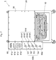
- the load testing apparatus 1 in the present embodiment can be also applied to a load testing apparatus for a low voltage corresponding to a low voltage power source as illustrated in Fig. 7 and can be also applied to a load testing apparatus for a high voltage corresponding to a high voltage power source as illustrated in Fig. 8 .
- an intake lid 32 and an exhaust lid 34 are omitted and an intake port 31 and an exhaust port 33 are always opened.
- an intake opening detection part 32b and an exhaust opening detection part 34b are omitted (see Fig. 7 ).
- the warning may be in a form of an output using light, may be in a form of a sound output, or may be in a warning form using both.
- auxiliary power source the power source for driving the load testing apparatus
- the off control may be performed.
- a protective relay 90 is provided on a power source line (particularly, on the power source line to the cooling fan 10) for supplying power from the auxiliary power source to the respective units (the cooling fan 10, the rotation state detection part 10a, the current/voltage detection part 20a, the temperature detection part 20b, the first actuator 32a, the intake opening detection part 32b, the second actuator 34a, the exhaust opening detection part 34b, and the control unit 80) of the load testing apparatus 1.
- the protective relay 90 detects the voltage applied to the load testing apparatus 1 (the cooling fan 10 and the like) via the power source line or the current flowing through the power source line.
- the protective relay 90 turns off the main switch 50 via the control unit 80 (or directly without via the control unit 80). In other words, the protective relay 90 performs the off control that stops power supply from the power source to be tested to the resistive unit 20.
- the warning may be in a form of displaying characters on the display device 70 or in a form of providing a warning part separately from the intake lid warning part 61a and the like.
- the warning may be in a form of lighting all of the intake lid warning part 61a, the exhaust lid warning part 61b, the cooling fan warning part 61c, the current/voltage warning part 61d, and the temperature warning part 61e to inform the abnormality.
- the respective units of the load testing apparatus 1 do not operate correctly, for example, the cooling fan 10 does not rotate sufficiently, the sensors, such as the rotation state detection part 10a, do not operate correctly, or the control unit 80 does not operate correctly.
- the load test cannot be performed normally.
- abnormality detection of the power supply source (the auxiliary power source or the cable) is performed based on the power supply state from the auxiliary power source serving as a source of driving the respective units of the load testing apparatus 1.
- the power supply from the auxiliary power source is performed normally, the power supply from the power source to be tested is enabled. Accordingly, it is possible to perform the abnormality detection or the load test of the load testing apparatus 1 correctly.
Landscapes
- Physics & Mathematics (AREA)
- General Physics & Mathematics (AREA)
- Engineering & Computer Science (AREA)
- Power Engineering (AREA)
- Tests Of Circuit Breakers, Generators, And Electric Motors (AREA)
- Testing Electric Properties And Detecting Electric Faults (AREA)
- Business, Economics & Management (AREA)
- Emergency Management (AREA)
Claims (7)
- Belastungsprüfeinrichtung (1), umfassend:eine mit Widerstand behaftete Einheit (20), die eine oder mehrere Gruppen von Widerständen mit einer Mehrzahl von Widerständen einschließt und an eine Stromquelle, die für eine Belastungsprüfung zu prüfen ist, anschließbar ist;einen Lüfter (10), ausgestaltet für das Kühlen der Widerstände in der mit Widerstand behafteten Einheit (20); undeinen Regler (80), dadurch gekennzeichnet, dasseine Ausströmklappe (34), die sich bei Gebrauch öffnet, an einem Ausströmschlitz (33) an einer der mit Widerstand behafteten Einheit (20) nachgeschalteten Stelle vorgesehen ist,
ein Ausströmöffnungsdetektionsteil (34b), das einen geöffiieten/geschlossenen Zustand der Ausströmklappe (34) detektiert, an dem Ausströmschlitz (33) oder der Ausströmklappe (34) vorgesehen ist, und
das Ausgestaltetsein des Reglers (80) für das Ausführen einer Aus-Regelung, die die Stromzufuhr von der zu prüfenden Stromquelle an die mit Widerstand behaftete Einheit (20) beendet, auf der Grundlage von Informationen von dem Ausströmöffnungsdetektionsteil (34b) und von: (i) Informationen über einen Strom, der durch die Widerstände, die Gruppen von Widerständen oder die mit Widerstand behaftete Einheit (20) fließt, oder über eine Spannung, die an die Widerstände, die Gruppen von Widerständen oder die mit Widerstand behaftete Einheit (20) angelegt ist; oder/und (ii) Informationen über eine Ausströmtemperatur an der der mit Widerstand behafteten Einheit (20) nachgeschalteten Stelle; oder/und (iii) Informationen über einen Drehzustand des Lüfters (10). - Belastungsprüfeinrichtung (1) nach Anspruch 1, ferner umfassend ein Schutzrelais (90), ausgestaltet für das Ausführen der Aus-Regelung auf der Grundlage von Informationen über einen Strom, der durch eine Stromquellenleitung von einer Ansteuerstromquelle fließt, die Strom liefert, der den Lüfter (10) ansteuert, oder über eine Spannung, die von der Ansteuerstromquelle über die Stromquellenleitung an die Belastungsprüfeinrichtung (1) angelegt ist.
- Belastungsprüfeinrichtung (1) nach Anspruch 1, wobei
eine Einlassklappe (32), die sich bei Gebrauch öffnet, an einem Einlassschlitz (31) des Lüfters (10) vorgesehen ist,
ein Einlassöffnungsdetektionsteil (32b), das einen geöffneten/geschlossenen Zustand der Einlassklappe (32) detektiert, an dem Einlassschlitz (31) oder der Einlassklappe (32) vorgesehen ist, und
der Regler (80) ferner für das Ausführen der Aus-Regelung auf der Grundlage von Informationen von dem Einlassöffiiungsdetektionsteil (32b) ausgestaltet ist. - Belastungsprüfeinrichtung (1) nach Anspruch 1, wobei der Regler (80) ferner so ausgestaltet ist, dass er:ein Stellglied (34a) ansteuert, das so ausgestaltet ist, dass es einen Arbeitsvorgang zum Öffnen der Ausströmklappe (34) ausführt; unddie Aus-Regelung startet, nachdem eine für das Öffnen der Ausströmklappe (34) durch das Stellglied (34a) benötigte Zeit seit dem Einschalten einer Hauptstromquelle der Belastungsprüfeinrichtung (1) abgelaufen ist.
- Belastungsprüfeinrichtung (1) nach Anspruch 1, ferner umfassend:ein Strom/Spannung-Warnteil (61d), das so ausgestaltet ist, dass es mittels Licht oder/und Ton anzeigt, dass die Aus-Regelung auf den Informationen über den Strom, der durch die Widerstände, die Gruppen von Widerständen oder die mit Widerstand behaftete Einheit (20) fließt, oder über die Spannung, die an die Widerstände, die Gruppen von Widerständen oder die mit Widerstand behaftete Einheit (20) angelegt ist, basiert;ein Temperaturwarnteil (61e), das so ausgestaltet ist, dass es mittels Licht oder/und Ton anzeigt, dass die Aus-Regelung auf den Informationen über die Ausströmtemperatur an der der mit Widerstand behafteten Einheit (20) nachgeschalteten Stelle basiert; undein Lüfterwarnteil (61c), das so ausgestaltet ist, dass es mittels Licht oder/und Ton anzeigt, dass die Aus-Regelung auf den Informationen über den Drehzustand des Lüfters (10) basiert.
- Belastungsprüfeinrichtung (1) nach Anspruch 5, wobei
die mit Widerstand behaftete Einheit (20) die zwei oder mehr Gruppen von Widerständen aufweist,
die Gruppe von Widerständen zwei oder mehr Wahlschalter (60b) einschließt, die für die Wahl, ob der Strom von der zu prüfenden Stromquelle geliefert wird oder nicht, verwendet werden,
ein Strom/Spannung-Detektionsteil (20a), das so ausgestaltet ist, dass es den Strom, der durch die Gruppen von Widerständen fließt, oder die Spannung, die an die Gruppen von Widerständen angelegt ist, detektiert, für jede Gruppe von Widerständen vorgesehen ist, und
als Strom/Spannung-Warnteil (61d) eine Beleuchtungsvorrichtung in der Nähe jedes der zwei oder mehr Wahlschalter (60b) vorgesehen ist. - Belastungsprüfeinrichtung (1) nach Anspruch 6, wobei der Regler (80) ferner so ausgestaltet ist, dass er:für die Gruppe von Widerständen, die als ein Objekt der Stromzufuhr aus der zu prüfenden Stromquelle über den Wahlschalter (60b) ausgewählt worden ist, bestimmt, ob ein Wert eines Stroms, der durch die Gruppe von Widerständen fließt, oder ein Wert einer Spannung, die an die Gruppe von Widerständen angelegt ist, innerhalb eines Bereichs während des Normalbetriebs liegt oder nicht; undfür die Gruppe von Widerständen, die nicht als Objekt der Stromzufuhr aus der zu prüfenden Stromquelle ausgewählt worden ist, bestimmt, ob der Strom durch die Gruppe von Widerständen fließt oder nicht oder ob die Spannung an die Gruppe von Widerständen angelegt ist oder nicht.
Applications Claiming Priority (2)
| Application Number | Priority Date | Filing Date | Title |
|---|---|---|---|
| PCT/JP2013/006809 WO2015075761A1 (ja) | 2013-11-20 | 2013-11-20 | 負荷試験装置 |
| PCT/JP2014/005601 WO2015075885A1 (ja) | 2013-11-20 | 2014-11-07 | 負荷試験装置 |
Publications (3)
| Publication Number | Publication Date |
|---|---|
| EP2913686A1 EP2913686A1 (de) | 2015-09-02 |
| EP2913686A4 EP2913686A4 (de) | 2016-08-03 |
| EP2913686B1 true EP2913686B1 (de) | 2017-02-01 |
Family
ID=51416797
Family Applications (1)
| Application Number | Title | Priority Date | Filing Date |
|---|---|---|---|
| EP14863074.2A Active EP2913686B1 (de) | 2013-11-20 | 2014-11-07 | Lasttester |
Country Status (11)
| Country | Link |
|---|---|
| US (1) | US9389250B2 (de) |
| EP (1) | EP2913686B1 (de) |
| JP (1) | JP5551324B1 (de) |
| KR (1) | KR101550657B1 (de) |
| CN (1) | CN104937430B (de) |
| CA (1) | CA2888376C (de) |
| MY (1) | MY171669A (de) |
| RU (1) | RU2577081C1 (de) |
| SG (1) | SG11201503241VA (de) |
| TW (1) | TWI516783B (de) |
| WO (2) | WO2015075761A1 (de) |
Families Citing this family (20)
| Publication number | Priority date | Publication date | Assignee | Title |
|---|---|---|---|---|
| WO2015075761A1 (ja) * | 2013-11-20 | 2015-05-28 | 株式会社辰巳菱機 | 負荷試験装置 |
| JP6332801B2 (ja) * | 2014-07-23 | 2018-05-30 | 株式会社辰巳菱機 | 負荷試験装置 |
| CN107155352B (zh) * | 2014-10-30 | 2018-06-15 | 株式会社辰巳菱机 | 负载试验装置 |
| JP2016133329A (ja) * | 2015-01-16 | 2016-07-25 | 株式会社辰巳菱機 | 負荷試験装置 |
| WO2017072818A1 (ja) * | 2015-10-30 | 2017-05-04 | 株式会社辰巳菱機 | シーズヒーター、負荷試験装置 |
| KR101685024B1 (ko) * | 2016-01-29 | 2016-12-09 | 주식회사 케이지에스 | 부하측정장치 |
| JP6275346B2 (ja) | 2016-02-25 | 2018-02-07 | 株式会社辰巳菱機 | 発電システム |
| KR101891802B1 (ko) * | 2017-02-16 | 2018-08-31 | 연세대학교 원주산학협력단 | 하드웨어 테스터기 |
| KR102073033B1 (ko) * | 2017-05-16 | 2020-02-04 | 가부시키가이샤다쓰미료키 | 부하 시스템, 부하 시험 장치 및 통신 단말 |
| JP7109859B2 (ja) * | 2018-01-16 | 2022-08-01 | 株式会社辰巳菱機 | 負荷試験装置 |
| WO2019175953A1 (ja) * | 2018-03-13 | 2019-09-19 | 株式会社辰巳菱機 | 負荷試験装置 |
| JP2020173179A (ja) * | 2019-04-11 | 2020-10-22 | 株式会社辰巳菱機 | 負荷試験装置、リレー異常検知システム |
| JP6757057B1 (ja) * | 2019-05-07 | 2020-09-16 | 株式会社辰巳菱機 | 負荷試験装置 |
| CN114207453B (zh) * | 2019-08-01 | 2024-03-19 | 株式会社辰巳菱机 | 负载试验装置 |
| US12140636B2 (en) * | 2020-06-04 | 2024-11-12 | Tatsumi Ryoki Co., Ltd | Load test device and cap of load test device |
| WO2022157959A1 (ja) * | 2021-01-25 | 2022-07-28 | 株式会社辰巳菱機 | 負荷試験装置 |
| CN116335634B (zh) * | 2021-12-24 | 2025-11-04 | 中国石油天然气集团有限公司 | 一种核磁共振测井仪高压发射模块快速检测装置与方法 |
| CN114509700B (zh) * | 2022-01-14 | 2024-01-12 | 苏州浪潮智能科技有限公司 | 一种服务器crps电源测试装置及方法 |
| CN115327189B (zh) * | 2022-07-13 | 2025-04-29 | 中国船舶电站设备有限公司 | 高压干式负载试验装置和设备 |
| JP7490292B1 (ja) * | 2023-02-02 | 2024-05-27 | 株式会社辰巳菱機 | 負荷試験システム |
Family Cites Families (23)
| Publication number | Priority date | Publication date | Assignee | Title |
|---|---|---|---|---|
| US5281908A (en) * | 1992-03-10 | 1994-01-25 | Tatsumi Corporation | Loading device assembly |
| FR2718584B1 (fr) * | 1994-04-08 | 1996-05-31 | Thomcast | Charge de puissance à refroidissement par air et antenne fictive constituée par une telle charge. |
| JP4073550B2 (ja) * | 1998-07-06 | 2008-04-09 | 株式会社辰巳菱機 | 発電機通電試験用負荷抵抗器 |
| US6078171A (en) * | 1998-08-21 | 2000-06-20 | Tatsumi Corporation | Dry type load resistor for testing generators or the like |
| US6324042B1 (en) * | 1999-03-12 | 2001-11-27 | Lynntech, Inc. | Electronic load for the testing of electrochemical energy conversion devices |
| BRPI0007931B1 (pt) * | 1999-12-02 | 2016-06-07 | Tatsumi Corp | aparelho com carga de teste a seco |
| CN1296169A (zh) * | 2000-12-26 | 2001-05-23 | 北京铁路分局丰台机务段 | 一种移动式干阻试验车设备 |
| JP4429831B2 (ja) * | 2003-10-29 | 2010-03-10 | 株式会社辰巳菱機 | 負荷装置 |
| US20060121421A1 (en) * | 2004-10-15 | 2006-06-08 | Spitaels James S | IT equipment simulation |
| JP2006145396A (ja) | 2004-11-19 | 2006-06-08 | Sharp Corp | バーンイン装置 |
| JP2006238681A (ja) * | 2005-01-26 | 2006-09-07 | Toyota Motor Corp | 負荷駆動装置の試験システムおよびその制御方法 |
| JP4315158B2 (ja) | 2006-01-06 | 2009-08-19 | 住友電気工業株式会社 | デバイス評価装置およびデバイス評価方法 |
| CN101587137A (zh) * | 2009-06-30 | 2009-11-25 | 朱晓明 | 一种集装箱式超大功率负载箱 |
| CN102129044A (zh) * | 2010-01-13 | 2011-07-20 | 鸿富锦精密工业(深圳)有限公司 | 电源测试系统 |
| CN201828578U (zh) * | 2010-09-26 | 2011-05-11 | 济南吉美乐电源技术有限公司 | 检修用便携式负载箱 |
| US9103895B2 (en) * | 2010-11-02 | 2015-08-11 | Schneider Electric USA, Inc. | Automated emergency power supply test using engine exhaust temperature |
| RU110193U1 (ru) * | 2011-07-06 | 2011-11-10 | Открытое акционерное общество "Научно-исследовательский институт электромеханики" (ОАО "НИИЭМ") | Датчик больших токов |
| US9291683B2 (en) * | 2011-10-11 | 2016-03-22 | General Electric Company | Power module protection at start-up |
| CN103064773A (zh) * | 2011-10-24 | 2013-04-24 | 鸿富锦精密工业(深圳)有限公司 | 测试负载卡 |
| CN202563073U (zh) * | 2012-05-11 | 2012-11-28 | 伟顺(中国)机电设备有限公司 | 一种负载测试仪 |
| CN103424580B (zh) * | 2012-05-15 | 2017-09-05 | 富泰华工业(深圳)有限公司 | 电子负载 |
| CN202975291U (zh) * | 2012-12-13 | 2013-06-05 | 吴江市华诚电子有限公司 | 一种负载箱 |
| WO2015075761A1 (ja) * | 2013-11-20 | 2015-05-28 | 株式会社辰巳菱機 | 負荷試験装置 |
-
2013
- 2013-11-20 WO PCT/JP2013/006809 patent/WO2015075761A1/ja not_active Ceased
- 2013-11-20 JP JP2014513810A patent/JP5551324B1/ja active Active
-
2014
- 2014-11-07 CN CN201480005706.5A patent/CN104937430B/zh active Active
- 2014-11-07 CA CA2888376A patent/CA2888376C/en active Active
- 2014-11-07 WO PCT/JP2014/005601 patent/WO2015075885A1/ja not_active Ceased
- 2014-11-07 EP EP14863074.2A patent/EP2913686B1/de active Active
- 2014-11-07 MY MYPI2015000917A patent/MY171669A/en unknown
- 2014-11-07 RU RU2015131845/28A patent/RU2577081C1/ru active
- 2014-11-07 SG SG11201503241VA patent/SG11201503241VA/en unknown
- 2014-11-07 KR KR1020157009855A patent/KR101550657B1/ko not_active Expired - Fee Related
- 2014-11-18 TW TW103139962A patent/TWI516783B/zh not_active IP Right Cessation
-
2015
- 2015-03-24 US US14/667,522 patent/US9389250B2/en active Active
Non-Patent Citations (1)
| Title |
|---|
| None * |
Also Published As
| Publication number | Publication date |
|---|---|
| RU2577081C1 (ru) | 2016-03-10 |
| CA2888376C (en) | 2016-06-28 |
| CN104937430A (zh) | 2015-09-23 |
| SG11201503241VA (en) | 2015-06-29 |
| US9389250B2 (en) | 2016-07-12 |
| EP2913686A4 (de) | 2016-08-03 |
| WO2015075885A1 (ja) | 2015-05-28 |
| EP2913686A1 (de) | 2015-09-02 |
| CN104937430B (zh) | 2016-08-31 |
| MY171669A (en) | 2019-10-22 |
| CA2888376A1 (en) | 2015-06-26 |
| TW201531724A (zh) | 2015-08-16 |
| JP5551324B1 (ja) | 2014-07-16 |
| WO2015075761A1 (ja) | 2015-05-28 |
| JPWO2015075761A1 (ja) | 2017-03-16 |
| KR101550657B1 (ko) | 2015-09-08 |
| TWI516783B (zh) | 2016-01-11 |
| US20150198636A1 (en) | 2015-07-16 |
Similar Documents
| Publication | Publication Date | Title |
|---|---|---|
| EP2913686B1 (de) | Lasttester | |
| EP3214454B1 (de) | Belastungstestvorrichtung | |
| KR20090084687A (ko) | 모터 제어 장치 및 모터의 절연 열화 검출 방법 | |
| CN100438313C (zh) | 负载驱动系统的故障检测装置 | |
| JP5082961B2 (ja) | 配電盤の交流電圧回路試験装置およびその方法 | |
| JP5758059B1 (ja) | 負荷試験装置 | |
| KR100944468B1 (ko) | 전동기 기동전류 제한용 리액터와 리액터 단락용 스위치부의 고장을 검출하는 고장검출장치와 이를 이용한 검출방법 | |
| CN105864007A (zh) | 用于压缩机控制回路的保护装置及其控制方法 | |
| CN107015108A (zh) | 用于在车辆中进行电功能测试的方法以及装置 | |
| KR101150503B1 (ko) | 회전자 권선 단락 진단 장치 및 회전자 권선 단락 진단 방법 | |
| HK1237877B (en) | Load testing device | |
| HK1237877A1 (en) | Load testing device | |
| CN108279342B (zh) | 一种元件的异电压性能测试系统 | |
| KR20120011674A (ko) | Eocr 테스트 장치 및 방법 | |
| US12230955B2 (en) | Industrial systems with integrated absence of voltage tester (AVT) and positive load indication (PLI) apparatus | |
| CN210465619U (zh) | 直流高电压高分断测试装置 | |
| KR20210057682A (ko) | 하이브리드 및 전기 차량 배터리 팩 유지 보수 장치 | |
| Portillo | Schneider motor protection system | |
| RO132220A0 (ro) | Aparat şi metodă pentru monitorizarea permanentă a dispozitivelor şi traseelor electrice din circuitele electrice de joasă tensiune, în scopul determinării preventive a anomaliilor de funcţionare carepot produce defecte, incendii sau explozii, şi evitării acestora, bazat pe analiza semnăturii electrice de funcţionare a circuitelor instalaţiei | |
| JPH088316A (ja) | 電力制御装置のパワートランジスタ劣化判定装置 |
Legal Events
| Date | Code | Title | Description |
|---|---|---|---|
| PUAI | Public reference made under article 153(3) epc to a published international application that has entered the european phase |
Free format text: ORIGINAL CODE: 0009012 |
|
| 17P | Request for examination filed |
Effective date: 20150528 |
|
| AK | Designated contracting states |
Kind code of ref document: A1 Designated state(s): AL AT BE BG CH CY CZ DE DK EE ES FI FR GB GR HR HU IE IS IT LI LT LU LV MC MK MT NL NO PL PT RO RS SE SI SK SM TR |
|
| AX | Request for extension of the european patent |
Extension state: BA ME |
|
| RA4 | Supplementary search report drawn up and despatched (corrected) |
Effective date: 20160630 |
|
| RIC1 | Information provided on ipc code assigned before grant |
Ipc: G01R 31/40 20060101ALI20160624BHEP Ipc: G01R 1/20 20060101ALI20160624BHEP Ipc: G01R 31/34 20060101AFI20160624BHEP |
|
| GRAP | Despatch of communication of intention to grant a patent |
Free format text: ORIGINAL CODE: EPIDOSNIGR1 |
|
| RIC1 | Information provided on ipc code assigned before grant |
Ipc: G01R 31/34 20060101AFI20160913BHEP Ipc: G01R 31/40 20060101ALI20160913BHEP Ipc: G01R 1/20 20060101ALI20160913BHEP |
|
| DAX | Request for extension of the european patent (deleted) | ||
| INTG | Intention to grant announced |
Effective date: 20161010 |
|
| RIN1 | Information on inventor provided before grant (corrected) |
Inventor name: KONDO, TOYOSHI |
|
| STAA | Information on the status of an ep patent application or granted ep patent |
Free format text: STATUS: GRANT OF PATENT IS INTENDED |
|
| GRAS | Grant fee paid |
Free format text: ORIGINAL CODE: EPIDOSNIGR3 |
|
| GRAA | (expected) grant |
Free format text: ORIGINAL CODE: 0009210 |
|
| STAA | Information on the status of an ep patent application or granted ep patent |
Free format text: STATUS: THE PATENT HAS BEEN GRANTED |
|
| AK | Designated contracting states |
Kind code of ref document: B1 Designated state(s): AL AT BE BG CH CY CZ DE DK EE ES FI FR GB GR HR HU IE IS IT LI LT LU LV MC MK MT NL NO PL PT RO RS SE SI SK SM TR |
|
| REG | Reference to a national code |
Ref country code: GB Ref legal event code: FG4D |
|
| REG | Reference to a national code |
Ref country code: CH Ref legal event code: EP Ref country code: AT Ref legal event code: REF Ref document number: 866020 Country of ref document: AT Kind code of ref document: T Effective date: 20170215 |
|
| REG | Reference to a national code |
Ref country code: IE Ref legal event code: FG4D |
|
| REG | Reference to a national code |
Ref country code: DE Ref legal event code: R096 Ref document number: 602014006663 Country of ref document: DE |
|
| REG | Reference to a national code |
Ref country code: NL Ref legal event code: MP Effective date: 20170201 |
|
| REG | Reference to a national code |
Ref country code: LT Ref legal event code: MG4D |
|
| REG | Reference to a national code |
Ref country code: AT Ref legal event code: MK05 Ref document number: 866020 Country of ref document: AT Kind code of ref document: T Effective date: 20170201 |
|
| PG25 | Lapsed in a contracting state [announced via postgrant information from national office to epo] |
Ref country code: IS Free format text: LAPSE BECAUSE OF FAILURE TO SUBMIT A TRANSLATION OF THE DESCRIPTION OR TO PAY THE FEE WITHIN THE PRESCRIBED TIME-LIMIT Effective date: 20170601 Ref country code: LT Free format text: LAPSE BECAUSE OF FAILURE TO SUBMIT A TRANSLATION OF THE DESCRIPTION OR TO PAY THE FEE WITHIN THE PRESCRIBED TIME-LIMIT Effective date: 20170201 Ref country code: NO Free format text: LAPSE BECAUSE OF FAILURE TO SUBMIT A TRANSLATION OF THE DESCRIPTION OR TO PAY THE FEE WITHIN THE PRESCRIBED TIME-LIMIT Effective date: 20170501 Ref country code: FI Free format text: LAPSE BECAUSE OF FAILURE TO SUBMIT A TRANSLATION OF THE DESCRIPTION OR TO PAY THE FEE WITHIN THE PRESCRIBED TIME-LIMIT Effective date: 20170201 Ref country code: GR Free format text: LAPSE BECAUSE OF FAILURE TO SUBMIT A TRANSLATION OF THE DESCRIPTION OR TO PAY THE FEE WITHIN THE PRESCRIBED TIME-LIMIT Effective date: 20170502 Ref country code: HR Free format text: LAPSE BECAUSE OF FAILURE TO SUBMIT A TRANSLATION OF THE DESCRIPTION OR TO PAY THE FEE WITHIN THE PRESCRIBED TIME-LIMIT Effective date: 20170201 |
|
| PG25 | Lapsed in a contracting state [announced via postgrant information from national office to epo] |
Ref country code: RS Free format text: LAPSE BECAUSE OF FAILURE TO SUBMIT A TRANSLATION OF THE DESCRIPTION OR TO PAY THE FEE WITHIN THE PRESCRIBED TIME-LIMIT Effective date: 20170201 Ref country code: LV Free format text: LAPSE BECAUSE OF FAILURE TO SUBMIT A TRANSLATION OF THE DESCRIPTION OR TO PAY THE FEE WITHIN THE PRESCRIBED TIME-LIMIT Effective date: 20170201 Ref country code: AT Free format text: LAPSE BECAUSE OF FAILURE TO SUBMIT A TRANSLATION OF THE DESCRIPTION OR TO PAY THE FEE WITHIN THE PRESCRIBED TIME-LIMIT Effective date: 20170201 Ref country code: BG Free format text: LAPSE BECAUSE OF FAILURE TO SUBMIT A TRANSLATION OF THE DESCRIPTION OR TO PAY THE FEE WITHIN THE PRESCRIBED TIME-LIMIT Effective date: 20170501 Ref country code: PT Free format text: LAPSE BECAUSE OF FAILURE TO SUBMIT A TRANSLATION OF THE DESCRIPTION OR TO PAY THE FEE WITHIN THE PRESCRIBED TIME-LIMIT Effective date: 20170601 Ref country code: SE Free format text: LAPSE BECAUSE OF FAILURE TO SUBMIT A TRANSLATION OF THE DESCRIPTION OR TO PAY THE FEE WITHIN THE PRESCRIBED TIME-LIMIT Effective date: 20170201 Ref country code: PL Free format text: LAPSE BECAUSE OF FAILURE TO SUBMIT A TRANSLATION OF THE DESCRIPTION OR TO PAY THE FEE WITHIN THE PRESCRIBED TIME-LIMIT Effective date: 20170201 Ref country code: ES Free format text: LAPSE BECAUSE OF FAILURE TO SUBMIT A TRANSLATION OF THE DESCRIPTION OR TO PAY THE FEE WITHIN THE PRESCRIBED TIME-LIMIT Effective date: 20170201 |
|
| PG25 | Lapsed in a contracting state [announced via postgrant information from national office to epo] |
Ref country code: CZ Free format text: LAPSE BECAUSE OF FAILURE TO SUBMIT A TRANSLATION OF THE DESCRIPTION OR TO PAY THE FEE WITHIN THE PRESCRIBED TIME-LIMIT Effective date: 20170201 Ref country code: EE Free format text: LAPSE BECAUSE OF FAILURE TO SUBMIT A TRANSLATION OF THE DESCRIPTION OR TO PAY THE FEE WITHIN THE PRESCRIBED TIME-LIMIT Effective date: 20170201 Ref country code: SK Free format text: LAPSE BECAUSE OF FAILURE TO SUBMIT A TRANSLATION OF THE DESCRIPTION OR TO PAY THE FEE WITHIN THE PRESCRIBED TIME-LIMIT Effective date: 20170201 Ref country code: RO Free format text: LAPSE BECAUSE OF FAILURE TO SUBMIT A TRANSLATION OF THE DESCRIPTION OR TO PAY THE FEE WITHIN THE PRESCRIBED TIME-LIMIT Effective date: 20170201 |
|
| REG | Reference to a national code |
Ref country code: DE Ref legal event code: R097 Ref document number: 602014006663 Country of ref document: DE |
|
| REG | Reference to a national code |
Ref country code: FR Ref legal event code: PLFP Year of fee payment: 4 |
|
| PG25 | Lapsed in a contracting state [announced via postgrant information from national office to epo] |
Ref country code: DK Free format text: LAPSE BECAUSE OF FAILURE TO SUBMIT A TRANSLATION OF THE DESCRIPTION OR TO PAY THE FEE WITHIN THE PRESCRIBED TIME-LIMIT Effective date: 20170201 Ref country code: SM Free format text: LAPSE BECAUSE OF FAILURE TO SUBMIT A TRANSLATION OF THE DESCRIPTION OR TO PAY THE FEE WITHIN THE PRESCRIBED TIME-LIMIT Effective date: 20170201 |
|
| PLBE | No opposition filed within time limit |
Free format text: ORIGINAL CODE: 0009261 |
|
| STAA | Information on the status of an ep patent application or granted ep patent |
Free format text: STATUS: NO OPPOSITION FILED WITHIN TIME LIMIT |
|
| 26N | No opposition filed |
Effective date: 20171103 |
|
| PG25 | Lapsed in a contracting state [announced via postgrant information from national office to epo] |
Ref country code: SI Free format text: LAPSE BECAUSE OF FAILURE TO SUBMIT A TRANSLATION OF THE DESCRIPTION OR TO PAY THE FEE WITHIN THE PRESCRIBED TIME-LIMIT Effective date: 20170201 |
|
| PG25 | Lapsed in a contracting state [announced via postgrant information from national office to epo] |
Ref country code: MC Free format text: LAPSE BECAUSE OF FAILURE TO SUBMIT A TRANSLATION OF THE DESCRIPTION OR TO PAY THE FEE WITHIN THE PRESCRIBED TIME-LIMIT Effective date: 20170201 |
|
| PG25 | Lapsed in a contracting state [announced via postgrant information from national office to epo] |
Ref country code: LI Free format text: LAPSE BECAUSE OF NON-PAYMENT OF DUE FEES Effective date: 20171130 Ref country code: CH Free format text: LAPSE BECAUSE OF NON-PAYMENT OF DUE FEES Effective date: 20171130 |
|
| PG25 | Lapsed in a contracting state [announced via postgrant information from national office to epo] |
Ref country code: LU Free format text: LAPSE BECAUSE OF NON-PAYMENT OF DUE FEES Effective date: 20171107 |
|
| REG | Reference to a national code |
Ref country code: BE Ref legal event code: MM Effective date: 20171130 |
|
| REG | Reference to a national code |
Ref country code: IE Ref legal event code: MM4A |
|
| PG25 | Lapsed in a contracting state [announced via postgrant information from national office to epo] |
Ref country code: MT Free format text: LAPSE BECAUSE OF NON-PAYMENT OF DUE FEES Effective date: 20171107 |
|
| PG25 | Lapsed in a contracting state [announced via postgrant information from national office to epo] |
Ref country code: IE Free format text: LAPSE BECAUSE OF NON-PAYMENT OF DUE FEES Effective date: 20171107 |
|
| PG25 | Lapsed in a contracting state [announced via postgrant information from national office to epo] |
Ref country code: BE Free format text: LAPSE BECAUSE OF NON-PAYMENT OF DUE FEES Effective date: 20171130 |
|
| PG25 | Lapsed in a contracting state [announced via postgrant information from national office to epo] |
Ref country code: HU Free format text: LAPSE BECAUSE OF FAILURE TO SUBMIT A TRANSLATION OF THE DESCRIPTION OR TO PAY THE FEE WITHIN THE PRESCRIBED TIME-LIMIT; INVALID AB INITIO Effective date: 20141107 |
|
| PG25 | Lapsed in a contracting state [announced via postgrant information from national office to epo] |
Ref country code: CY Free format text: LAPSE BECAUSE OF FAILURE TO SUBMIT A TRANSLATION OF THE DESCRIPTION OR TO PAY THE FEE WITHIN THE PRESCRIBED TIME-LIMIT Effective date: 20170201 |
|
| PG25 | Lapsed in a contracting state [announced via postgrant information from national office to epo] |
Ref country code: MK Free format text: LAPSE BECAUSE OF FAILURE TO SUBMIT A TRANSLATION OF THE DESCRIPTION OR TO PAY THE FEE WITHIN THE PRESCRIBED TIME-LIMIT Effective date: 20170201 |
|
| PG25 | Lapsed in a contracting state [announced via postgrant information from national office to epo] |
Ref country code: TR Free format text: LAPSE BECAUSE OF FAILURE TO SUBMIT A TRANSLATION OF THE DESCRIPTION OR TO PAY THE FEE WITHIN THE PRESCRIBED TIME-LIMIT Effective date: 20170201 |
|
| PG25 | Lapsed in a contracting state [announced via postgrant information from national office to epo] |
Ref country code: NL Free format text: LAPSE BECAUSE OF FAILURE TO SUBMIT A TRANSLATION OF THE DESCRIPTION OR TO PAY THE FEE WITHIN THE PRESCRIBED TIME-LIMIT Effective date: 20170201 |
|
| PG25 | Lapsed in a contracting state [announced via postgrant information from national office to epo] |
Ref country code: AL Free format text: LAPSE BECAUSE OF FAILURE TO SUBMIT A TRANSLATION OF THE DESCRIPTION OR TO PAY THE FEE WITHIN THE PRESCRIBED TIME-LIMIT Effective date: 20170201 |
|
| PGFP | Annual fee paid to national office [announced via postgrant information from national office to epo] |
Ref country code: IT Payment date: 20221124 Year of fee payment: 9 Ref country code: FR Payment date: 20221129 Year of fee payment: 9 |
|
| PG25 | Lapsed in a contracting state [announced via postgrant information from national office to epo] |
Ref country code: FR Free format text: LAPSE BECAUSE OF NON-PAYMENT OF DUE FEES Effective date: 20231130 |
|
| PG25 | Lapsed in a contracting state [announced via postgrant information from national office to epo] |
Ref country code: FR Free format text: LAPSE BECAUSE OF NON-PAYMENT OF DUE FEES Effective date: 20231130 |
|
| PG25 | Lapsed in a contracting state [announced via postgrant information from national office to epo] |
Ref country code: IT Free format text: LAPSE BECAUSE OF NON-PAYMENT OF DUE FEES Effective date: 20231107 |
|
| PG25 | Lapsed in a contracting state [announced via postgrant information from national office to epo] |
Ref country code: IT Free format text: LAPSE BECAUSE OF NON-PAYMENT OF DUE FEES Effective date: 20231107 |
|
| PGFP | Annual fee paid to national office [announced via postgrant information from national office to epo] |
Ref country code: DE Payment date: 20251119 Year of fee payment: 12 |
|
| PGFP | Annual fee paid to national office [announced via postgrant information from national office to epo] |
Ref country code: GB Payment date: 20251121 Year of fee payment: 12 |