EP2913695A2 - Terminaison de connecteur optique - Google Patents
Terminaison de connecteur optique Download PDFInfo
- Publication number
- EP2913695A2 EP2913695A2 EP15156877.1A EP15156877A EP2913695A2 EP 2913695 A2 EP2913695 A2 EP 2913695A2 EP 15156877 A EP15156877 A EP 15156877A EP 2913695 A2 EP2913695 A2 EP 2913695A2
- Authority
- EP
- European Patent Office
- Prior art keywords
- terminus
- end portion
- ferrule
- lens
- rear end
- Prior art date
- Legal status (The legal status is an assumption and is not a legal conclusion. Google has not performed a legal analysis and makes no representation as to the accuracy of the status listed.)
- Withdrawn
Links
- 230000003287 optical effect Effects 0.000 title claims abstract description 41
- 239000000835 fiber Substances 0.000 claims description 43
- 230000013011 mating Effects 0.000 claims description 6
- 230000003667 anti-reflective effect Effects 0.000 claims 1
- 239000013307 optical fiber Substances 0.000 abstract description 19
- 239000004593 Epoxy Substances 0.000 description 11
- 230000005540 biological transmission Effects 0.000 description 9
- 239000000463 material Substances 0.000 description 6
- 238000005516 engineering process Methods 0.000 description 5
- 230000008901 benefit Effects 0.000 description 3
- 238000009434 installation Methods 0.000 description 3
- 239000000853 adhesive Substances 0.000 description 2
- 230000001070 adhesive effect Effects 0.000 description 2
- 238000013461 design Methods 0.000 description 2
- 238000003780 insertion Methods 0.000 description 2
- 230000037431 insertion Effects 0.000 description 2
- 230000007246 mechanism Effects 0.000 description 2
- 239000002184 metal Substances 0.000 description 2
- 229910052751 metal Inorganic materials 0.000 description 2
- 238000000034 method Methods 0.000 description 2
- 230000008569 process Effects 0.000 description 2
- RYGMFSIKBFXOCR-UHFFFAOYSA-N Copper Chemical compound [Cu] RYGMFSIKBFXOCR-UHFFFAOYSA-N 0.000 description 1
- 239000006117 anti-reflective coating Substances 0.000 description 1
- 238000003491 array Methods 0.000 description 1
- 239000000919 ceramic Substances 0.000 description 1
- 229910010293 ceramic material Inorganic materials 0.000 description 1
- 230000008859 change Effects 0.000 description 1
- 238000004891 communication Methods 0.000 description 1
- 238000010276 construction Methods 0.000 description 1
- 238000011109 contamination Methods 0.000 description 1
- 230000008602 contraction Effects 0.000 description 1
- 229910052802 copper Inorganic materials 0.000 description 1
- 239000010949 copper Substances 0.000 description 1
- 230000001419 dependent effect Effects 0.000 description 1
- 230000003670 easy-to-clean Effects 0.000 description 1
- 229920006332 epoxy adhesive Polymers 0.000 description 1
- 238000001914 filtration Methods 0.000 description 1
- 239000011521 glass Substances 0.000 description 1
- 230000036039 immunity Effects 0.000 description 1
- 238000007373 indentation Methods 0.000 description 1
- 238000012986 modification Methods 0.000 description 1
- 230000004048 modification Effects 0.000 description 1
- 238000000465 moulding Methods 0.000 description 1
- 229920003023 plastic Polymers 0.000 description 1
- 230000008054 signal transmission Effects 0.000 description 1
- 230000003746 surface roughness Effects 0.000 description 1
Images



Classifications
-
- G—PHYSICS
- G02—OPTICS
- G02B—OPTICAL ELEMENTS, SYSTEMS OR APPARATUS
- G02B6/00—Light guides; Structural details of arrangements comprising light guides and other optical elements, e.g. couplings
- G02B6/24—Coupling light guides
- G02B6/36—Mechanical coupling means
- G02B6/38—Mechanical coupling means having fibre to fibre mating means
- G02B6/3807—Dismountable connectors, i.e. comprising plugs
- G02B6/3833—Details of mounting fibres in ferrules; Assembly methods; Manufacture
- G02B6/3853—Lens inside the ferrule
-
- G—PHYSICS
- G02—OPTICS
- G02B—OPTICAL ELEMENTS, SYSTEMS OR APPARATUS
- G02B6/00—Light guides; Structural details of arrangements comprising light guides and other optical elements, e.g. couplings
- G02B6/24—Coupling light guides
- G02B6/26—Optical coupling means
- G02B6/32—Optical coupling means having lens focusing means positioned between opposed fibre ends
- G02B6/322—Optical coupling means having lens focusing means positioned between opposed fibre ends and having centering means being part of the lens for the self-positioning of the lightguide at the focal point, e.g. holes, wells, indents, nibs
-
- G—PHYSICS
- G02—OPTICS
- G02B—OPTICAL ELEMENTS, SYSTEMS OR APPARATUS
- G02B6/00—Light guides; Structural details of arrangements comprising light guides and other optical elements, e.g. couplings
- G02B6/24—Coupling light guides
- G02B6/36—Mechanical coupling means
- G02B6/38—Mechanical coupling means having fibre to fibre mating means
- G02B6/3807—Dismountable connectors, i.e. comprising plugs
- G02B6/3873—Connectors using guide surfaces for aligning ferrule ends, e.g. tubes, sleeves, V-grooves, rods, pins, balls
- G02B6/3874—Connectors using guide surfaces for aligning ferrule ends, e.g. tubes, sleeves, V-grooves, rods, pins, balls using tubes, sleeves to align ferrules
- G02B6/3878—Connectors using guide surfaces for aligning ferrule ends, e.g. tubes, sleeves, V-grooves, rods, pins, balls using tubes, sleeves to align ferrules comprising a plurality of ferrules, branching and break-out means
Definitions
- the present invention relates to the field of fiber optics. More particularly, the present invention relates to the facilitation of optical signals from one optical fiber to another via an expanded beam optical interface.
- optical signals are utilized to transmit data, particularly over long distances.
- the optical signals are transmitted through fiber optic cables, which are designed to propagate a light signal through the cable via complete internal reflection.
- Optical cables are superior to copper-based cables because they are flexible and may contain numerous optical fibers.
- optical signals are preferred to electromagnetic signals over longer distances because features such as lower signal attenuation and larger bandwidth capacity.
- optical signals are versatile and may be integrated into a sensor arrays to provide feedback for such conditions as strain, temperature, pressure, and rotation.
- Optical sensors may be preferred over mechanical and electric sensors because of their smaller size, lower or nonexistent power demands, and immunity to electromagnetic interference.
- one limitation of fiber optic transmissions is that the light signal must be precisely transferred from one cable to another, as any optical loss can attenuate the signal dramatically.
- a physical contact fiber-optic connector two optical cables are guided against and affixed to ceramic ferrules that precisely direct the light signal from one to the other.
- the ferrules on each side are polished precisely so that the light signal is conserved as much as possible from the source to the destination cable.
- An alignment retainer and axial spring can be used to ensure proper alignment. Issues that arise in a physical contact connector assembly include loss of signal due to a space between ferrules, improper alignment of the ferrules against one another, and improper alignment of the optical fiber cables.
- Expanded beam technology for fiber-optic connectors provides an alternative means of fiber-optic transmission.
- a ferrule guides the light signal from a source cable to a lens. The signal is then refocused by a second lens and directed to its destination.
- One benefit of this technology is that there is no contact requirement for the fiber optic cables. Consequently, this technology prevents mechanical wear and contamination build-up on connector components that could attenuate the light signal.
- An alignment retainer is shown, for instance, in FIGS. 5A , B.
- the alignment retainer contains alignment cavities that each receive a fiber optic terminus from either end, so that the fiber optic terminus can interface in the middle of the cavity.
- an optical connector terminus that includes a terminus body, a ferrule, and a molded lens, as three distinct parts.
- the terminus body is modular and designed to fit any commercially available connector cavity on a fiber optic cable. Epoxy and/or a crimp ring may be used to attach the terminus body and fiber optic cable more permanently.
- An inserted fiber optic cable passes through the terminus body and ferrule.
- the ferrule is designed to guide the connector through the connector until it contacts with the molded lens.
- the molded lens is modular and designed to light signals from the fiber and ensure conservative transmission to a second receiving lensed terminus over an air gap for eventual transmission to a second fiber optics cable.
- the molded lens can be designed to transmit the light signal of any commercially available optical fiber cable.
- alternate embodiments of the molded lens are capable of transmitting light signals of different wavelengths and focal lengths.
- an optical connector terminus comprised of a terminus body and a removable, modular integrated ferrule and molded lens component.
- the terminus body is also modular and removable. It directs the fiber optic cable through to the integrated ferrule and molded lens.
- the optical fiber cable contacts with the molded lens, which directs the light signal from the fiber through and focuses or processes it for transmission to a second receiving lensed terminus.
- an optical connector terminus comprised of a single integrated terminus body, ferrule, and molded lens.
- the terminus body portion of the integrated connector allows for the fiber optic cable pass to the ferrule, which directs it to contact with the integrated molded lens.
- the molded lens then focuses or processes the light signal from the cable for transmission to a second receiving lensed terminus.
- the integrated molded lens can be designed to transmit the light signal of any commercially available optical fiber cable.
- alternate embodiments of the molded lens are capable of transmitting light signals of different wavelengths and focal lengths.
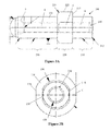
- FIGS. 1-3 show a two-piece apparatus 5 and FIG. 4 shows a one-piece optical terminus 10.
- FIG. 1 shows the overall implementation of the invention in accordance with a non-limiting illustrative embodiment.
- the optical connector terminus generally includes a terminus body 100, a ferrule 200, and a molded lens 300.
- the front portion of the terminus body 100 connects with the rear portion of the ferrule 200.
- the rear portion of the terminus body 100 receives a commercially available fiber optic cable 7.
- the front portion of the ferrule 200 is integrally formed with the modular molded lens 300.
- the molded lens 300 focuses a light signal from the received fiber optic cable 7 so that it can be transmitted to a second receiving lensed terminus for transmission to a second commercially available fiber optic cable.
- the terminus body 100, the ferrule 200, and the molded lens 300 can be used to transmit signals from multiple types of optical fiber cable types with variable light wavelengths and focal lengths.
- the inserted fiber optic cable 7 may be comprised of multiple individual optical fibers.
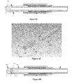
- the molded lens 300 is formed integral with the ferrule 200, it can also be formed as a separate piece that is connected to (such as being snapped) the front portion of the ferrule 200 (see FIG. 6C ).
- the lens 300 can also be made of glass and adhered to the ferrule 200.
- all three components of the invention can be removable and modular prior to final assembly.
- the terminus body 100 is shown in further detail.
- the terminus body 100 is elongated and has a rear end portion 110, a middle portion 120 and a front end portion 130 that is opposite the rear end portion 110.
- the terminus body 100 forms a single integral body having a longitudinal shape with a circular cross section.
- the front end portion 130 has the largest outer diameter, and is configured to receive the ferrule 200.
- the middle portion 120 has a reduced outer diameter with respect to the front end portion 130. In this manner, the larger front end portion 130 is able to accommodate the enlarged opening 194 and also form a surface, to retain the ferrule 200.
- the rear end portion 110 has a reduced outer diameter with respect to the middle portion 120 and the front end portion 130.
- a first shoulder 132 is formed where the front end portion 130 meets the middle portion 120.
- a clip on the connector can releasably engage the first shoulder 132 to lock the connector to the apparatus 5.
- a second shoulder 122 is formed where the middle portion 120 meets the rear portion 110.
- the rear end portion 110 retains the cable, whereby a sleeve of the cable slides over the top surface of the rear end portion 110 and can optionally abut up against the second shoulder 122 (or even the first shoulder 132) with the top of the cable being flush with the top of the second shoulder 122 (or first shoulder 132).
- a curved bottom 112 is provided at the bottom of the second shoulder 122 to provide stress relief.
- the rear end portion 110 of the terminus body 100 is mated to a commercially available fiber optic cable, preferably using epoxy or a crimp ring. Specifically, the distal end of the rear end portion 1100 of the terminus body 100 slides into the connector cavity, allowing the fiber optic cable 7 to enter the hollow bore 190 of the end portion of the terminus body.
- a central bore 190 extends the entire length of the terminus body 100.
- the bore 190 extends from the rear end portion 110, through the middle portion 120, and partway into the front end 130 of the terminus body 100.
- the central bore 190 receives a fiber optic cable 7 and forms a terminus wall 101 having an inner surface 103 that forms the outer boundaries of the bore 190.
- An enlarged opening 194 is formed at the proximal end 130 of the terminus body 100.
- the enlarged opening 194 forms a circular wall 134 at the distal end of the front end portion 130.
- the enlarged opening 194 is formed at the distal end of the front end portion 130 and receives the ferrule 200.
- the bore 190 has a first tapered section 192 at the far end of the rear end portion 110 of the terminus body 100.
- the first tapered section 192 expands outward to form a larger opening at the distal end of the rear end portion 110.
- the first tapered section 192 guides the optical fiber into the bore 190 and reduces stubbing.
- a second tapered section 196 is provided at the distal end of the front end portion 130.
- the second tapered section 196 expands outward at the distal end to form a larger opening at the distal end of the front end portion 130.
- the second tapered section 196 guides the ferrule 200 into the enlarged opening 194.
- all components of the optics connector 5 are fabricated from polymeric material (though other material can be used), and is rigid and inflexible.
- at least the rear end portion 110 of the terminus body is fabricated from metal, and the entire terminus body 100 can be fabricated from metal.
- the ferrule 200 is shown in further detail.
- the ferrule 200 is elongated and has a circular cross section.
- the ferrule body 200 includes a rear end portion 210, a middle portion 220, a front end portion 230, and a molded lens 300.
- the rear end portion 210 has an outer distal end 212 that is tapered inward slightly.
- the middle portion 220 has a wider diameter and forms a stop 222 with a rear shoulder 224 and a curved front shoulder 226.
- the front shoulder 226 is curved to ease insertion into connector grommet.
- the front end portion 230 and the rear end portion 210 each have an outer diameter that is substantially the same.
- the front end portion 230 can be slidably received in a mating connector, such as the cavities of the alignment retainer of FIGS. SA, B, until the front shoulder 226 is reached at which point insertion is stopped.
- a mating connector such as the cavities of the alignment retainer of FIGS. SA, B
- the rear end portion 210 has an open distal end
- the front end portion 230 has a closed distal end formed by a the rear surface of the lens 300.
- the ferrule 200 has a central bore 240 with a uniform diameter that extends the entire length of the ferrule body 200.
- the bore 240 forms a ferrule wall 201.
- the bore 240 is tapered 242 outward slightly at the distal end of the rear end portion 210 of the ferrule 200.
- the tapered portion 242 guides the fiber optic cable into the bore 240 without stubbing.
- the outside of the ferrule body 200 and the stop member 222 can have straight portions 138, 136 respectively, at positions A, B, C, for molding purposes.
- the molded lens 300 is integrally formed with the front end portion 230 of the ferrule 200, so that the ferrule 200 is a one-piece element with the molded lens 300.
- the lens 300 has a diameter that is slightly smaller than the diameter of the front end portion 230. Accordingly, there is a lip 302 between the lens 300 and the front end portion 230. The lip 302 ensures that the lens 300 does not come into contact with an alignment retainer cavity in which the front end portion 230 can be inserted. The lip 302 further aids in the moldability of the lens surface.
- the lens 300 focuses the light signal 9 from the inserted fiber optic cable 7. The light is then transmitted to a second receiving lensed terminus for transmission to a second fiber optic cable. It should be understood that the inserted fiber optic cable 7 may be comprised of multiple optical fibers.
- the rear portion 210 of the ferrule 200 is removably received and couples with the front portion 130 of the terminus body 100. More particularly, the rear portion 210 of the ferrule 200 is received within the enlarged opening 194, within the annular wall 134. The wall of the rear portion 210 of the ferrule 200 slides into the front end portion 130 of the terminus 100 until the leading front edge of the wall 134 contacts the shoulder 224 of the stop member 222. The rear end 210 of the ferrule 200 is shorter in length than depth of the enlarged opening 194 (and therefore also shorter than the wall 134 of the front end portion 130 of the terminus 100).
- the leading front face of the wall 134 will come into contact with the shoulder 224 of the stop member 222 and the leading front face of the rear end 210 of the ferrule 200 will not contact the bottom of the enlarged opening 194.
- the gap 244 is created because the ferrule 200 stops when the shoulder 224 ( FIG. 3A ) engages the distal leading edge of the front end portion 130.
- the gap 244 also acts as a reservoir for excess epoxy when the rear and front are glued together.
- the outer diameter of the stop 220 is the same as the outer diameter of the front end portion 130 of the terminus 100.
- the ferrule 200 forms a tight friction fit or a bonded fit with the terminus 100.
- the bore 240 of the ferrule 200 is aligned with the bore 190 of the terminus. Accordingly, the fiber optic cable 7 can slide through the bore 190 of the terminus body 100, into the bore 240 of the ferrule, and to the rear surface 304 of the lens. The cable 7 comes flush with the rear face 304 of the lens 300.
- the ferrule bore 240 is substantially equal to the diameter of the hollow bore 190 of the terminus body 100.
- the ferrule bore 240 accepts the inserted fiber optic cable 7 and guides it into the proper position against the rear surface 304 of the molded lens 300.
- the cable 7 can be fixed to the rear surface 304 of the lens 300 by epoxy or the like. A small opening can be provided in the side of the ferrule 200 to allow excess epoxy to escape when the cable 7 is inserted into the bore 240.
- the rear end portion 110 has an outer diameter of about 0.067 inches.
- the middle portion 120 has a diameter of approximately 0.106 inches.
- the diameter of the hollow bore 190 of the terminus body 100 is uniform, about 0.043 inches.
- the enlarged opening 194 has a diameter of 0.0900 inches.
- the front portion 130 has an outer diameter of about 0.133 inches.
- the rear end portion 110 has a length of about 0.229 inches.
- the distal end 112 preferably has an outer diameter substantially equal to 0.067 inches.
- the distal end 112 preferably has a length substantially equal to 0.229 inches.
- the enlarged opening 194 can have a uniform diameter substantially equal to 0.090 inches.
- the front portion 130 of the terminus body preferably has an outer diameter substantially equal to 0.133 inches, inclusive of the outer rim that contacts the shoulder 220 of the ferrule 200.
- the inserted fiber optic cable 7 is at a distance substantially equal to 0.0591 inches from the outermost point of the molded lens 300 within a tolerance of ⁇ 0.0008 inches.
- the ferrule 200 including the molded lens 300 is transparent ( i.e., clear). It can be fabricated from various polymeric materials.
- the molded lens 300 has an anti-reflective coating, preferably with a reflective average less than 0.25% for 650 nm at a 0° angle of incidence.
- the molded lens 300 preferably has the following optical properties: (1) a radius of curvature substantially equal to 0.0465 inches; (2) a clear aperture substantially equal to 0.071; (3) a diameter substantially equal to 0.080 inches; (4) a scratch-dig specification substantially equal to 60-40; and (5) a surface roughness specification (RMS) that is less than 80 ⁇ or 50 ⁇ .
- the molded lens 300 focuses the light signal 9 originating from the inserted fiber optic cable 7.
- the light signal that exits the molded lens 300 as a beam with a width substantially equivalent to the clear aperture of the molded lens 300.
- the light signal is then available for transmission to a second receiving lensed terminus, which will proceed to refocus the light signal and transmit it through a second fiber optic cable.
- the apparatus 5 is a two-piece device, namely a terminus 100 and a ferrule 300, and that the molded lens 300 is shown and described as being integral with the ferrule 200.
- the terminus 100 and ferrule 300 can be separately molded or machined, and each form a single-piece unitary element.
- the two-piece design allows the terminus 100 to be interchanged to provide for different rear ends, such as either crimp or epoxy termination. It also allows the lens 300 to be replaced, and provides greater manufacturability.
- the lens 300 can be a separate piece that is removably received at the front end 230 of the ferrule 200.
- the lens 300 can snap into place, so that the molded lens 300 is removable and modular. Still yet, the lens 300 can be bonded to the ferrule 200. In these manners, the assembly 5 can fit a variety of commercially available optical fiber cables, and permutations of molded lenses 300 capable of transmitting light signals of different wavelengths and focal lengths.
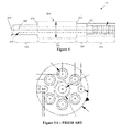
- the entire apparatus 10 is comprised of a single integrated unitary terminus body 400.
- the entire optics connector terminus 400 is preferably fabricated out of optically clear polymeric material.
- the terminus body 400 includes a crimp portion 410, rear end portion 420, middle portion 430 and front end portion 440.
- the crimp portion 410 attaches the apparatus 400 by crimp ring or epoxy to the outer jacket and strength member of a commercially available fiber optic cable.
- the rear end portion 420 has a diameter that is larger than the diameter of the crimp portion 410 and forms a shoulder 422 between the rear end portion 420 and the crimp portion 410.
- the middle portion 430 has a diameter that is larger than the diameter of the rear end portion 420 and forms a shoulder 432 between the middle portion 430 and the rear end portion 420.
- the front end portion 440 has a diameter that is smaller than the diameter of the middle portion 430, such that a shoulder 434 is formed between the middle portion 430 and the front end portion 440.
- One or more of the shoulders 422, 432, 434 can be used as a stop mechanism to prevent the terminus body 400 from being inserted too far in a receiving alignment device.
- a lens 450 front surface is formed along with the front of the lens rear surface 442.
- a bore 402 of uniform diameter extends the entire length of the body 400, up to the lens rear surface 442.
- An optical fiber is received in the bore 402 and passes the entire length of the body 400 to the rear side 442 of the lens 450.
- the optical fiber transmits light through the lens 450 refracting surface, which focuses the light.
- the cable can also be fixed to the rear lens surface 442 by epoxy or the like.
- a small opening can be provided in the side of the front end portion 440 to allow excess epoxy to escape when the cable is inserted into the bore 402.
- the cable portion 410 can be comprised of ribs that facilitate in gripping the inserted optical fiber cable 7.
- the first gap in the ribs preferably appears a distance substantially equal to 0.026 inches from the outermost point of rear end portion 420.
- Each gap's indentation is preferably substantially equal to 0.003 inches.
- Each gap has a width substantially equal to 0.019 inches.
- the inserted fiber optic cable 7 is threaded into the rear end portion 420 and through the entire length of the hollow bore 402.
- the hollow bore 402 is uniform in diameter and extends longitudinally through the entire length of the rear end portion 420, middle portion 430 and partway through the front end portion 440.
- the hollow bore 402 terminates at the rear lens surface 442, which is substantially equal to 0.0590 inches from the outermost point of the molded lens 450.
- the diameter of the hollow bore 402 is uniform, preferably substantially equal to 0.042 inches.
- the embodiment of FIG. 3 provides a single integrated connector body 400.
- the lens 450 can be fashioned as a separate device that is attached to the front end portion 440, such as being snap fit or by bonding.
- the lens 450 can have the same properties as in the earlier embodiments.
- the body 400 can also be made of the same materials as the earlier embodiments, and can be transparent optically ( i.e., clear) at the wavelengths of interest.
- the size of the bore and the dimensions of the terminus can be adjusted to receive different size fiber optic cables.
- the invention has been described as having a circular cross section and bore, other shapes can be provided.
- the apparatus 15 includes a ferrule having a ferrule body 500 and a terminus having a terminus body 600.
- the ferrule body 500 is an elongated single-piece member with a circular cross-section.
- the ferrule body 500 has a front end portion 510 and a rear end portion 530 and an intermediate or middle portion 520 therebetween.
- the middle portion 520 includes an outward projection 522 that forms a lip 524 that forms a front stop. Though the projection 522 is shown at the middle portion 520, it can be provided at any suitable position, such as at the front portion 510.
- the rear end portion 530 has an outer surface with one or more raised ridges 532.
- the further inward ridge 532 has a lip 534.
- An optical cable can be engaged to the rear end portion 530 by a clamp 675 that is crimped to the ridges 532 of the rear end portion 530.
- the terminus body 600 is an elongated hollow tube having a circular cross-section and a central bore.
- the diameter of the terminus body 600 is larger than the diameter of the ferrule body 500, so that the terminus body 600 extends over at least the middle portion 520 of the ferrule body 500.
- the terminus body 600 is slightly larger than the projection 522, so that the projection 522 forms a snug fit with the terminus body 600 at a front end 604 of the terminus body 600.
- the rear end 606 of the terminus body 600 has a smaller diameter to form a lip 610 that operates as a rear stop.
- the smaller rear end portion 606 is slightly larger than the ferrule body 500 to form a snug fit with the ferrule body 500.
- a circular channel 525 is formed between the outer surface of the ferrule body 500 and the inner surface of the terminus body 600.
- the channel 525 is closed at its front end by the outward projection 522 of the ferrule 500, and at its rear end by the inward rear end portion 606.
- the distal rear end of the rear end portion 606 is tapered inward slightly to form a lip 612.
- the terminus lip 612 is configured to engage with the ridge lip 534.
- a spring 575 is positioned in the channel 525 about the ferrule body 500.
- the spring 575 engages the front stop 524 of the projection 522 and the rear stop 610 of the rear end portion 606, which cooperate to prevent the spring 575 from escaping the channel 525.
- the apparatus 15 is assembled by placing the spring 575 about the middle portion 520 of the ferrule body 500, so it rests on the front stop 524.
- the ferrule 500 is then slidably received in the terminus 600.
- the ferrule 500 is pushed all the way through the terminus 600 against the force of the spring 575 until the rear end portion 530 of the ferrule 500 emerges out from the rear end portion 606 of the terminus body 600.
- the ferrule 500 is then released, and the spring pushes outward on the ferrule 500 against the front and rear stops 524, 610.
- the ferrule 500 will come to rest when the ridge lip 534 engages the terminus rear lip 612.
- the cable can then be crimped to the rear end portion 530 of the ferrule 500.
- the ferrule 500 is then slidably engaged with the terminus 600 against the force of the spring 575. Accordingly, the ferrule 500 can be moved in/out of the terminus 600 by pushing inward on the ferrule 500.
- the spring 575 holds the terminus in a fixed position and prevents axial movement.
- a lens 550 is provided at the distal front end of the front end portion 510.
- the lens 550 is integrally formed with the ferrule 500 so that the ferrule 500 and lens 550 is a single-piece member.
- the entire apparatus 15 has two pieces: the ferrule 500 with the lens 550, and the terminus 600.
- the lens 550 can instead be fashioned as a separate piece that is connected to the body 502 of the ferrule 500.
- the lens 550 can have a small central bore 552 that forms a small circular opening and a circumferential wall 554.
- a circular projection or plug 512 can be formed at the distal front end of the ferrule 500 that has a reduced diameter with respect to the ferrule body 502.
- the lens 550 can then be friction fit to the ferrule 500 by pushing the plug 512 into the bore 552.
- the lens 550 can come into contact with the forward-facing surface 504 of the ferrule body 502.
- the apparatus 15 has three pieces: the ferrule 500, the lens 550, and the terminus 600.
- different lenses 550 having different optical properties (such as focal distance or filtering) can be fitted to the ferrule 500.
- the removable lens 550 can be used in the earlier embodiments of FIGS. 1-4 (see FIG. 6C ) as well as in the spring embodiments of FIGS. 6A-B (FIG. D).
- any suitable connection can be made between the lens 550 and the ferrule 500.
- the lens 550 can be adhered to the ferrule and need not have a plug and bore configuration.
- the present invention allows for quick field installation through the use of Ultra Violet (UV) light-curing epoxy. It has a finite conjugate expanded beam that comes to focus and collimates when heated and can work over a large temperature range.
- UV-transparent plastic allows UV-light to cure adhesives in addition to heat curable adhesives in the center bore.
- the terminus of the present invention can operate over a wide temperature range, from at least -55° to 100° C.
- the design has a thermally dependent varying focus.
- the lens focal length varies over temperature while transmitting light between mated lens pairs within clear aperture and the angular acceptance range (numerical aperture) of the receiving fiber.
- the focus of the lens changes over temperature from a foxed focal point to a collimating beam as the temperature changes from -55° to 100° C.
- the terminus lens can have convex refractive or diffractive optical elements.
- FIG. 7 One non-limiting illustrative use of the two-piece optical apparatus 5 and/or one-piece optical terminus 15 of the present invention is shown in FIG. 7 .
- a connector is providing having a first mating connector 570 and a second mating connector 580.
- An adapter 572, 582 is provided in each connector 570, 580, respectively.
- Each of the adapters 572, 582 have a first bore that receives a first terminus 5, 15, and a second bore that receives a second terminus 5, 15. At least the distal ends of the ferrules 200 project out of the adapters 572, 582 and are slidably received by a central alignment retainer 550.
- the first termini 5, 15 of each adapter 572, 582 are received in a first bore of the retainer 550 so that they face each other, and the second two termini 5, 15 are received in a second bore to face each other. Accordingly, light passes out of the lens 300 of one of the termini 5, 15 in each bore, and into the lens 300 of the termini 5, 15 facing it in that bore. Accordingly, when the first and second connectors 570, 580 are brought together, the first and second termini 5, 15 are aligned with to be in optical communication with the respective termini 5, 15 in the other connector 570, 580.
- the termini 5, 15 can be utilized in other connectors and configurations, and need not be in the connector of FIG. 7 .
Landscapes
- Physics & Mathematics (AREA)
- General Physics & Mathematics (AREA)
- Optics & Photonics (AREA)
- Optical Couplings Of Light Guides (AREA)
Applications Claiming Priority (1)
| Application Number | Priority Date | Filing Date | Title |
|---|---|---|---|
| US14/194,045 US20150247981A1 (en) | 2014-02-28 | 2014-02-28 | Optical connector terminus |
Publications (2)
| Publication Number | Publication Date |
|---|---|
| EP2913695A2 true EP2913695A2 (fr) | 2015-09-02 |
| EP2913695A3 EP2913695A3 (fr) | 2015-12-09 |
Family
ID=52577774
Family Applications (1)
| Application Number | Title | Priority Date | Filing Date |
|---|---|---|---|
| EP15156877.1A Withdrawn EP2913695A3 (fr) | 2014-02-28 | 2015-02-27 | Terminaison de connecteur optique |
Country Status (5)
| Country | Link |
|---|---|
| US (1) | US20150247981A1 (fr) |
| EP (1) | EP2913695A3 (fr) |
| CN (1) | CN104880778A (fr) |
| BR (1) | BR102015004223A2 (fr) |
| CA (1) | CA2883181A1 (fr) |
Cited By (1)
| Publication number | Priority date | Publication date | Assignee | Title |
|---|---|---|---|---|
| EP3182182A1 (fr) | 2015-12-15 | 2017-06-21 | Radiall S.A. | Dispositif pour coupler deux fibres optiques, destiné à être utilisé dans des connecteurs |
Families Citing this family (3)
| Publication number | Priority date | Publication date | Assignee | Title |
|---|---|---|---|---|
| US9879361B2 (en) | 2012-08-24 | 2018-01-30 | Domtar Paper Company, Llc | Surface enhanced pulp fibers, methods of making surface enhanced pulp fibers, products incorporating surface enhanced pulp fibers, and methods of making products incorporating surface enhanced pulp fibers |
| US10698165B2 (en) * | 2013-03-15 | 2020-06-30 | Te Connectivity Corporation | Multi-fiber ferrule connector |
| US10176463B2 (en) * | 2015-12-17 | 2019-01-08 | International Business Machines Corporation | Machine learning system for intelligently identifying suitable time slots in a user's electronic calendar |
Family Cites Families (12)
| Publication number | Priority date | Publication date | Assignee | Title |
|---|---|---|---|---|
| US4735477A (en) * | 1984-12-11 | 1988-04-05 | Amp Incorporated | Fiber optic splice terminal and method of using same |
| US4781431A (en) * | 1986-12-29 | 1988-11-01 | Labinal Components And Systems, Inc. | Lensed optical connector |
| US5097524A (en) * | 1990-05-17 | 1992-03-17 | G & H Technology, Inc. | Optical fiber termination |
| US5363461A (en) * | 1993-07-20 | 1994-11-08 | Bergmann Ernest E | Field installable optical fiber connectors |
| JP4071407B2 (ja) * | 1999-11-08 | 2008-04-02 | 矢崎総業株式会社 | 光コネクタ用スリーブ、及びレセプタクル |
| JP2006276566A (ja) * | 2005-03-30 | 2006-10-12 | Molex Inc | 光コネクタ |
| US7775725B2 (en) * | 2008-10-29 | 2010-08-17 | Tyco Electronics Corporation | Single-channel expanded beam connector |
| US20110229077A1 (en) * | 2010-03-19 | 2011-09-22 | Davide Domenico Fortusini | Small-form-factor fiber optic interface devices with an internal lens |
| US8827567B2 (en) * | 2011-08-10 | 2014-09-09 | Tyco Electronics Corporation | Field-installable expanded beam connector system |
| US9360630B2 (en) * | 2011-08-31 | 2016-06-07 | Volcano Corporation | Optical-electrical rotary joint and methods of use |
| JP5754317B2 (ja) * | 2011-09-15 | 2015-07-29 | 富士通株式会社 | 光コネクタ |
| WO2013074803A1 (fr) * | 2011-11-15 | 2013-05-23 | Molex Incorporated | Connecteur de fibres optiques à large plage de température avec compensation de dilatation thermique |
-
2014
- 2014-02-28 US US14/194,045 patent/US20150247981A1/en not_active Abandoned
-
2015
- 2015-02-26 CA CA2883181A patent/CA2883181A1/fr not_active Abandoned
- 2015-02-26 BR BR102015004223-0A patent/BR102015004223A2/pt not_active Application Discontinuation
- 2015-02-27 EP EP15156877.1A patent/EP2913695A3/fr not_active Withdrawn
- 2015-03-02 CN CN201510093392.5A patent/CN104880778A/zh active Pending
Non-Patent Citations (1)
| Title |
|---|
| None |
Cited By (1)
| Publication number | Priority date | Publication date | Assignee | Title |
|---|---|---|---|---|
| EP3182182A1 (fr) | 2015-12-15 | 2017-06-21 | Radiall S.A. | Dispositif pour coupler deux fibres optiques, destiné à être utilisé dans des connecteurs |
Also Published As
| Publication number | Publication date |
|---|---|
| BR102015004223A2 (pt) | 2020-05-26 |
| EP2913695A3 (fr) | 2015-12-09 |
| US20150247981A1 (en) | 2015-09-03 |
| CA2883181A1 (fr) | 2015-08-28 |
| CN104880778A (zh) | 2015-09-02 |
Similar Documents
| Publication | Publication Date | Title |
|---|---|---|
| ES2908843T3 (es) | Carcasa de la férula con bota integrada | |
| CN101852897B (zh) | 单通道扩束光连接器 | |
| US6648521B2 (en) | Single terminus connector with preterminated fiber and fiber guide tube | |
| US7331719B2 (en) | Optical fiber clamping assembly | |
| MX2020002280A (es) | Conector de fibra óptica de diseño compacto con un capuchón de múltiples usos. | |
| EP0032722B1 (fr) | Connecteurs pour fibres optiques | |
| US20060002662A1 (en) | Small form factor, field-installable connector | |
| EP2913695A2 (fr) | Terminaison de connecteur optique | |
| US12222561B2 (en) | Pre-connectorized multi-fiber drop cables and methods for deploying and assembling pre-connectorized multi-fiber drop cables | |
| EP3182182A1 (fr) | Dispositif pour coupler deux fibres optiques, destiné à être utilisé dans des connecteurs | |
| EP2549313B1 (fr) | Embout doté d'un alignement de fibres intégré | |
| US20220269015A1 (en) | Fiber optic connector | |
| GB2253072A (en) | Lensed optic fibre connector having internally reflective tube | |
| US20170052321A1 (en) | Fused expanded beam connector | |
| EP1644764B1 (fr) | Ensemble de serrage de fibres optiques | |
| US20140376860A1 (en) | Optical coupling member and optical connector | |
| CN115552301A (zh) | 光纤支撑结构 | |
| US7334944B1 (en) | Optical connector | |
| CN101681003B (zh) | 用于光纤的阳接头 | |
| US20170017040A1 (en) | Collimating lens | |
| JPWO2021192746A5 (fr) | ||
| EP4091007B1 (fr) | Câbles de dérivation à fibres multiples pré-équipés de connecteurs | |
| US10663673B2 (en) | Fiber optic connectors having diamond-like carbon thin film coated optical fibers | |
| JP5460621B2 (ja) | 光コネクタ及び光コネクタの組立方法 |
Legal Events
| Date | Code | Title | Description |
|---|---|---|---|
| PUAI | Public reference made under article 153(3) epc to a published international application that has entered the european phase |
Free format text: ORIGINAL CODE: 0009012 |
|
| AK | Designated contracting states |
Kind code of ref document: A2 Designated state(s): AL AT BE BG CH CY CZ DE DK EE ES FI FR GB GR HR HU IE IS IT LI LT LU LV MC MK MT NL NO PL PT RO RS SE SI SK SM TR |
|
| AX | Request for extension of the european patent |
Extension state: BA ME |
|
| PUAL | Search report despatched |
Free format text: ORIGINAL CODE: 0009013 |
|
| AK | Designated contracting states |
Kind code of ref document: A3 Designated state(s): AL AT BE BG CH CY CZ DE DK EE ES FI FR GB GR HR HU IE IS IT LI LT LU LV MC MK MT NL NO PL PT RO RS SE SI SK SM TR |
|
| AX | Request for extension of the european patent |
Extension state: BA ME |
|
| RIC1 | Information provided on ipc code assigned before grant |
Ipc: G02B 6/38 20060101AFI20151103BHEP |
|
| STAA | Information on the status of an ep patent application or granted ep patent |
Free format text: STATUS: THE APPLICATION IS DEEMED TO BE WITHDRAWN |
|
| 18D | Application deemed to be withdrawn |
Effective date: 20160610 |