EP2913709A1 - Immersives projektionssystem - Google Patents
Immersives projektionssystem Download PDFInfo
- Publication number
- EP2913709A1 EP2913709A1 EP15163394.8A EP15163394A EP2913709A1 EP 2913709 A1 EP2913709 A1 EP 2913709A1 EP 15163394 A EP15163394 A EP 15163394A EP 2913709 A1 EP2913709 A1 EP 2913709A1
- Authority
- EP
- European Patent Office
- Prior art keywords
- projectors
- enclosure
- gantry
- projection system
- mounting frame
- Prior art date
- Legal status (The legal status is an assumption and is not a legal conclusion. Google has not performed a legal analysis and makes no representation as to the accuracy of the status listed.)
- Withdrawn
Links
Images






Classifications
-
- E—FIXED CONSTRUCTIONS
- E04—BUILDING
- E04H—BUILDINGS OR LIKE STRUCTURES FOR PARTICULAR PURPOSES; SWIMMING OR SPLASH BATHS OR POOLS; MASTS; FENCING; TENTS OR CANOPIES, IN GENERAL
- E04H3/00—Buildings or groups of buildings for public or similar purposes; Institutions, e.g. infirmaries or prisons
- E04H3/10—Buildings or groups of buildings for public or similar purposes; Institutions, e.g. infirmaries or prisons for meetings, entertainments, or sports
- E04H3/22—Theatres; Concert halls; Studios for broadcasting, cinematography, television or similar purposes
-
- G—PHYSICS
- G03—PHOTOGRAPHY; CINEMATOGRAPHY; ANALOGOUS TECHNIQUES USING WAVES OTHER THAN OPTICAL WAVES; ELECTROGRAPHY; HOLOGRAPHY
- G03B—APPARATUS OR ARRANGEMENTS FOR TAKING PHOTOGRAPHS OR FOR PROJECTING OR VIEWING THEM; APPARATUS OR ARRANGEMENTS EMPLOYING ANALOGOUS TECHNIQUES USING WAVES OTHER THAN OPTICAL WAVES; ACCESSORIES THEREFOR
- G03B21/00—Projectors or projection-type viewers; Accessories therefor
- G03B21/14—Details
-
- E—FIXED CONSTRUCTIONS
- E04—BUILDING
- E04H—BUILDINGS OR LIKE STRUCTURES FOR PARTICULAR PURPOSES; SWIMMING OR SPLASH BATHS OR POOLS; MASTS; FENCING; TENTS OR CANOPIES, IN GENERAL
- E04H15/00—Tents or canopies, in general
- E04H15/20—Tents or canopies, in general inflatable, e.g. shaped, strengthened or supported by fluid pressure
- E04H15/22—Tents or canopies, in general inflatable, e.g. shaped, strengthened or supported by fluid pressure supported by air pressure inside the tent
-
- G—PHYSICS
- G03—PHOTOGRAPHY; CINEMATOGRAPHY; ANALOGOUS TECHNIQUES USING WAVES OTHER THAN OPTICAL WAVES; ELECTROGRAPHY; HOLOGRAPHY
- G03B—APPARATUS OR ARRANGEMENTS FOR TAKING PHOTOGRAPHS OR FOR PROJECTING OR VIEWING THEM; APPARATUS OR ARRANGEMENTS EMPLOYING ANALOGOUS TECHNIQUES USING WAVES OTHER THAN OPTICAL WAVES; ACCESSORIES THEREFOR
- G03B21/00—Projectors or projection-type viewers; Accessories therefor
-
- G—PHYSICS
- G03—PHOTOGRAPHY; CINEMATOGRAPHY; ANALOGOUS TECHNIQUES USING WAVES OTHER THAN OPTICAL WAVES; ELECTROGRAPHY; HOLOGRAPHY
- G03B—APPARATUS OR ARRANGEMENTS FOR TAKING PHOTOGRAPHS OR FOR PROJECTING OR VIEWING THEM; APPARATUS OR ARRANGEMENTS EMPLOYING ANALOGOUS TECHNIQUES USING WAVES OTHER THAN OPTICAL WAVES; ACCESSORIES THEREFOR
- G03B21/00—Projectors or projection-type viewers; Accessories therefor
- G03B21/14—Details
- G03B21/28—Reflectors in projection beam
-
- G—PHYSICS
- G03—PHOTOGRAPHY; CINEMATOGRAPHY; ANALOGOUS TECHNIQUES USING WAVES OTHER THAN OPTICAL WAVES; ELECTROGRAPHY; HOLOGRAPHY
- G03B—APPARATUS OR ARRANGEMENTS FOR TAKING PHOTOGRAPHS OR FOR PROJECTING OR VIEWING THEM; APPARATUS OR ARRANGEMENTS EMPLOYING ANALOGOUS TECHNIQUES USING WAVES OTHER THAN OPTICAL WAVES; ACCESSORIES THEREFOR
- G03B21/00—Projectors or projection-type viewers; Accessories therefor
- G03B21/54—Accessories
- G03B21/56—Projection screens
-
- G—PHYSICS
- G03—PHOTOGRAPHY; CINEMATOGRAPHY; ANALOGOUS TECHNIQUES USING WAVES OTHER THAN OPTICAL WAVES; ELECTROGRAPHY; HOLOGRAPHY
- G03B—APPARATUS OR ARRANGEMENTS FOR TAKING PHOTOGRAPHS OR FOR PROJECTING OR VIEWING THEM; APPARATUS OR ARRANGEMENTS EMPLOYING ANALOGOUS TECHNIQUES USING WAVES OTHER THAN OPTICAL WAVES; ACCESSORIES THEREFOR
- G03B21/00—Projectors or projection-type viewers; Accessories therefor
- G03B21/54—Accessories
- G03B21/56—Projection screens
- G03B21/58—Projection screens collapsible, e.g. foldable; of variable area
-
- G—PHYSICS
- G03—PHOTOGRAPHY; CINEMATOGRAPHY; ANALOGOUS TECHNIQUES USING WAVES OTHER THAN OPTICAL WAVES; ELECTROGRAPHY; HOLOGRAPHY
- G03B—APPARATUS OR ARRANGEMENTS FOR TAKING PHOTOGRAPHS OR FOR PROJECTING OR VIEWING THEM; APPARATUS OR ARRANGEMENTS EMPLOYING ANALOGOUS TECHNIQUES USING WAVES OTHER THAN OPTICAL WAVES; ACCESSORIES THEREFOR
- G03B21/00—Projectors or projection-type viewers; Accessories therefor
- G03B21/54—Accessories
- G03B21/56—Projection screens
- G03B21/58—Projection screens collapsible, e.g. foldable; of variable area
- G03B21/585—Inflatable screens
-
- G—PHYSICS
- G03—PHOTOGRAPHY; CINEMATOGRAPHY; ANALOGOUS TECHNIQUES USING WAVES OTHER THAN OPTICAL WAVES; ELECTROGRAPHY; HOLOGRAPHY
- G03B—APPARATUS OR ARRANGEMENTS FOR TAKING PHOTOGRAPHS OR FOR PROJECTING OR VIEWING THEM; APPARATUS OR ARRANGEMENTS EMPLOYING ANALOGOUS TECHNIQUES USING WAVES OTHER THAN OPTICAL WAVES; ACCESSORIES THEREFOR
- G03B21/00—Projectors or projection-type viewers; Accessories therefor
- G03B21/54—Accessories
- G03B21/56—Projection screens
- G03B21/60—Projection screens characterised by the nature of the surface
- G03B21/62—Translucent screens
-
- G—PHYSICS
- G03—PHOTOGRAPHY; CINEMATOGRAPHY; ANALOGOUS TECHNIQUES USING WAVES OTHER THAN OPTICAL WAVES; ELECTROGRAPHY; HOLOGRAPHY
- G03B—APPARATUS OR ARRANGEMENTS FOR TAKING PHOTOGRAPHS OR FOR PROJECTING OR VIEWING THEM; APPARATUS OR ARRANGEMENTS EMPLOYING ANALOGOUS TECHNIQUES USING WAVES OTHER THAN OPTICAL WAVES; ACCESSORIES THEREFOR
- G03B37/00—Panoramic or wide-screen photography; Photographing extended surfaces, e.g. for surveying; Photographing internal surfaces, e.g. of pipe
- G03B37/04—Panoramic or wide-screen photography; Photographing extended surfaces, e.g. for surveying; Photographing internal surfaces, e.g. of pipe with cameras or projectors providing touching or overlapping fields of view
-
- G—PHYSICS
- G06—COMPUTING OR CALCULATING; COUNTING
- G06F—ELECTRIC DIGITAL DATA PROCESSING
- G06F3/00—Input arrangements for transferring data to be processed into a form capable of being handled by the computer; Output arrangements for transferring data from processing unit to output unit, e.g. interface arrangements
- G06F3/01—Input arrangements or combined input and output arrangements for interaction between user and computer
- G06F3/011—Arrangements for interaction with the human body, e.g. for user immersion in virtual reality
-
- H—ELECTRICITY
- H04—ELECTRIC COMMUNICATION TECHNIQUE
- H04N—PICTORIAL COMMUNICATION, e.g. TELEVISION
- H04N9/00—Details of colour television systems
- H04N9/12—Picture reproducers
- H04N9/31—Projection devices for colour picture display, e.g. using electronic spatial light modulators [ESLM]
- H04N9/3141—Constructional details thereof
- H04N9/3147—Multi-projection systems
Definitions
- Immersive viewing environments are useful in a variety of applications, including entertainment, gaming, military and civilian training, or other kinds of training.
- a user may be surrounded or substantially surrounded by a projection screen that displays a representation of an environment, and the user has the impression of being immersed in the environment.
- the scene may be an immersive motion picture.
- Some systems are interactive, so that the user can navigate through the environment, with the scene automatically updating to reflect simulated motion through the displayed environment.
- Prior immersive viewing systems have disadvantages. For example, systems may require a large number of projectors to cover the entire projection screen.
- the environment representation is formed by a number of projectors, each displaying part of the scene on the viewing screen. In such systems, the user can only move in a very limited part of the enclosed area without casting shadows on the viewing screen.
- Prior systems are also difficult and time consuming to set up.
- an immersive projection system includes an enclosure having a perimeter wall and a top portion, and a set of projectors suspended outside the enclosure at the top portion of the enclosure.
- the projectors are configured to project imagery through openings in the perimeter wall and onto an inside surface of the perimeter wall.
- the enclosure may be a collapsible dome. In some embodiments, when deployed, the dome approximately defines a portion of a sphere. In some embodiments, the imagery forms a continuous scene representation surrounding a center portion of the enclosure.
- the shape of the enclosure is maintained by positive air pressure within the collapsible dome, such that the perimeter wall defines the dome shape. The shape of the enclosure may be maintained in part by negative air pressure within the enclosure as compared with the atmosphere outside the enclosure.
- the set of projectors includes no more than five projectors.
- the set of projectors comprises a plurality of projectors, each projector aimed inward toward a central axis, and light emanated by the projectors falls directly onto the perimeter wall.
- the set of projectors comprises a plurality of projectors, each projector aimed inward toward a central axis; the immersive projection system further comprises one or more mirrors suspended in the upper portion of the enclosure at the central axis; and light emanated by each projector reflects from one of the one or more mirrors before being cast onto the perimeter wall.
- the one or more mirrors consist of only a single spherical mirror.
- the one or more mirrors comprise one and only one convex mirror face for each projector.
- Each convex mirror face may define a segment of a sphere.
- Each convex mirror face may be aspheric.
- the immersive projection system further comprises a mounting frame onto which the plurality of projectors is mounted, the mounting frame holding the plurality of projectors in fixed spatial relationship.
- the immersive projection system may further comprise a movable gantry to which the mounting frame is attached, the gantry configured to raise the mounting frame from a position facilitating assembly of the system to position at the upper portion of the enclosure.
- the immersive projection system further comprises one or more mirrors mounted to the mounting frame, wherein light emanated by each projector reflects from one of the one or more mirrors before being cast onto the perimeter wall, and wherein the mounting frame holds the plurality of projectors and the one or more mirrors in fixed spatial relationship.
- a structure for supporting one or more projectors in an immersive projection system comprises at least two towers, a gantry suspended between the two towers and movable vertically, and a mounting frame affixed to the gantry.
- the mounting frame comprises mounting points for mounting one or more projectors.
- the structure further comprises one or more mirrors fixed to the mounting frame such that projectors mounted to the mounting points aim toward the one or more mirrors.
- the gantry may be movable from a position facilitating assembly of the system to a position at the upper portion of the enclosure.
- the structure further comprises the one or more projectors, and an enclosure having a perimeter wall, the enclosure being collapsible, wherein an upper portion of the perimeter wall is configured to be raised by the raising of the gantry.
- a method of assembling a projection system comprises the steps of erecting two towers, connecting a movable gantry between the two towers, positioning the movable gantry at a height that facilitates assembly of the system, and affixing a mounting frame to the movable gantry.
- the mounting frame includes mounting points for one or more projectors.
- the method further includes mounting one or more projectors to the mounting points, and raising the gantry to its working height.
- the method further comprises connecting an upper portion of a perimeter wall of an enclosure to the mounting frame such that each of the one or more projectors projects imagery through a respective opening in the perimeter wall, and such that raising the gantry raises the upper portion of the perimeter wall to its working height.
- the method may further include pressurizing the enclosure.
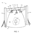
- FIG 1 is an external view of an immersive projection system 100, in accordance with an embodiment.
- the system includes an enclosure 101 that includes a perimeter wall 102, which surrounds a user 103.
- Perimeter wall 102 has an inside surface 104, and a set of projectors 105a-105e projects imagery onto inside surface 104, through openings in perimeter wall 102.
- the images projected by projectors 105a-105e are coordinated and create a seamless 360-degree representation of an environment, so that user 103 has the experience of being immersed in the environment. While the system illustrated in Figure 1 completely surrounds user 103, the principles of the invention may be embodied in systems that only partially surround the user.
- Enclosure 101 also includes a top portion 106, and projectors 105a-105e are positioned at top portion 106, so that user 103 has freedom of movement within a relatively large portion of enclosure 101 without casting shadows on inner surface 104 by interrupting the projection of light from projectors 105a-105e.
- enclosure 101 may be made of a collapsible material, for example a cloth or other flexible material.
- Enclosure 101 may be fabricated in such a way that any seams are unobtrusive, so as to minimize their tendency to distract from the immersive experience.
- a fabric enclosure 101 may be pieced from segments that are precisely cut and joined by laser stitching, heat welding, an adhesive, or another technique that results in unobtrusive joints between dome segments.
- the dome shape of enclosure 101 may be maintained by pressurizing the interior of enclosure 101 using a fan or other air source, not shown.
- the lower perimeter of enclosure 101 may be weighted to hold enclosure 101 against the floor when inflated.
- enclosure 101 may include a supporting frame and the interior of enclosure 101 may be held at a negative pressure with respect to the atmosphere outside the enclosure, so that the dome shape is maintained by the frame and the negative air pressure.
- projectors 105a-105e are mounted on a mounting frame 107, which maintains the projectors in a fixed spatial relationship.
- projectors 105a-105e are aimed inward toward a central axis 110.
- Mounting frame 107 is in turn mounted on a gantry 108, which is movable vertically along towers 109a and 109b. The vertical movement may be accomplished by any suitable mechanism, for example a crank and pulley system, a leadscrew, or other mechanism, and may be manually operated or motorized.
- the gantry system and collapsible dome combine to enable system 100 to be set up quickly and easily.
- the components of system 100 may be shipped to a usage site, and towers 109a and 109b and gantry 108 assembled.
- Gantry 108 may be placed at a low level, for example ground level or waist height, so that assemblers can attach mounting frame 107, projectors 105a-105e, and collapsible perimeter wall 102.
- Gantry 108 can then be raised and enclosure 101 inflated to complete the mechanical setup of the system.
- Various electrical connections will also be made, as described in more detail below.
- projectors 105a-105e may be changed easily. For example, a particular installation may be upgraded to projectors having higher resolution by changing the projectors, while the other mechanical parts of the system remain the same. Different projectors may simply be attached to mounting points on mounting frame 107. Or different installations may use different projectors, for example to meet different cost or performance targets. Any suitable projectors may be utilized, but one example of a suitable projector for some embodiments is a model F35 projector with RGB VizSim color wheel and a resolution of 2560 X 1600 pixels, available from projectiondesign a/s of Fredrikstad, Norway.
- projectors 105a-105e project directly onto opposing portions of inner surface 104.
- Figure 2 shows an orthogonal cutaway view of system 100 according to this arrangement. Only projectors 105a and 105c are shown in this view for clarity. Inner surface portion 201 is illuminated by projector 105a, and inner surface portion 202 is illuminated by projector 105c. The view of Figure 2 is simplified, and does not depict the full areas illuminated by the projectors. Other projectors illuminate other parts of inner surface 104, so that a complete 360-degree view is created. The areas illuminated by adjacent projectors may overlap.
- system 100 includes five projectors 105a-105c, more or fewer projectors may be utilized.
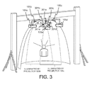
- Figure 3 shows an oblique cutaway view of another embodiment.
- mirrors 301a-301e are positioned in front of projectors 105a-105c. Light from each projector 105a-105e is reflected from its corresponding mirror 301a-301e, and illuminates a portion of interior surface 204 near the respective projector.
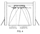
- Figure 4 shows an orthogonal view of the system of Figure 3 , illustrating the parts of inner surface 104 illuminated by projectors 105a and 105c.
- the illuminated areas shown in Figures 3 and 4 are schematic only, and may not reflect exact shapes of illuminated areas. In practice, the shapes of the areas illuminated by the projectors will depend on the shape of the enclosure wall, the shapes of mirrors 301a-301e, and other factors.
- each mirror may increase the available volume within enclosure 101 for movement of the user, as compared with the embodiment of Figure 2 .
- the shape of each mirror is selected for good optical performance of the system, and may depend on the shape of enclosure 101.
- each of mirrors 301a-301e is convex.
- the front surface of each of mirrors 301a-301e may be a portion of a sphere, although aspheric shapes can also be used.
- Figures 3 and 4 uses one mirror per projector, other arrangements are possible.
- a single spherical mirror may be used, and light from all of the projectors may reflect from different portions of the single spherical surface.
- spherical means that the mirror surface defines at least a portion of a sphere, but a "spherical” mirror need not define a complete sphere.
- Figure 5 illustrates a cross section view of an embodiment using a mirror 501 that defines a portion of a sphere, and is therefore considered to be spherical.
- enclosure 502 also approximately defines a portion of a sphere.
- Other mathematically-definable enclosure shapes are possible as well.
- Figure 6 illustrates how the areas illuminated by different projectors in the embodiment of Figure 5 overlap.
- only one projector 601 is shown, reflecting light from spherical mirror 501, illuminating area 602 on interior surface 603.
- Another projector may illuminate area 604, shown outlined in dashed lines.
- Figure 6 may be a more accurate depiction of the illuminated areas and their overlap for a particular configuration of mirror 501 and surface 603, it is still only exemplary, and other particular configurations may include illuminated regions having somewhat different shapes than those shown in Figure 6 .
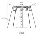
- Figures 7-10 depict a particular embodiment of a structure for supporting a mirror, projectors, and an enclosure, although the projectors and enclosure itself are not shown.
- Figure 7 is a front view
- Figure 8 is a side view
- Figure 9 is a top view of the structure.
- Figure 10 shows an oblique view. Referring to Figure 10 , mirror 501, mounting frame 107, gantry 108, and towers 109a and 109b are visible.
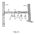
- Figure 11 shows one example installation of a portion of an immersive projection system according to embodiments, at an intermediate stage of assembly.
- gantry 108 is held at about head level, and projectors 105a-105b have been attached to mounting frame 107.
- the system may position the gantry at other heights convenient for assembly, for example floor level or waist level.
- the capability to lower projectors 105a-105b to a convenient working height greatly simplifies the setup of the system.
- Figure 12 shows the system with enclosure 101 installed, and gantry 108 raised to its working height.
- Figure 12 also shows an example entrance and egress port 1201 providing access to the interior of enclosure 101 .
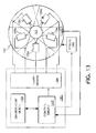
- Figure 13 illustrates an electronic architecture of the system, according to one embodiment.
- a computerized controller 1301 coordinates operation of the system.
- a control engine 1302 interacts with an environment model 1303 to determine where a user of the system is virtually positioned within a computer generated environment.
- Environment model 1303 may include, for example, a digitized description of a simulation environment, and logic or software to provide images of the environment from different vantage points.
- Control engine determines from the user's virtual position what imagery should be projected on enclosure 101 by each of projectors 105a-105b.
- warp engine 1304 pre-distorts the selected imagery so that, given the particular projectors in use, the shape of mirror 501, the shape of enclosure 101, and the projected image overlap, the resulting projected images will appear correct and undistorted to the user after projection onto enclosure 101.
- sensors 1305 may be provided within enclosure 101.
- sensors 1305 may include simulated controls for an airplane. When the user actuates the simulated controls, control engine 1302 models how the simulated airplane would react, determines the trajectory of the airplane within the model environment, obtains the corresponding imagery from environment model 1303, and provides that information to warp engine 1304.
- Warp engine 1304 computes new pre-distorted imagery and feeds it to projectors 105a-105e for projection on enclosure 101. With the projected imagery updated, the user has the perception that the "airplane" he or she is flying reacted in a realistic way to his or her control inputs.
- sensors 1305 may include a treadmill that measures travel of the user as the user "walks" through the simulated environment, so that the projected imagery can be updated to reflect the user's simulated movements. Many other kinds of sensors may be utilized.
- controller 1301 may simply replay previously-recorded content for viewing by a user 103.
- the previously-recorded content may be an immersive motion picture.
- Control engine 1302 may also be able to cause certain other special effects 1306 to occur within enclosure 101.
- the temperature within enclosure 101 could be changed to correspond to changes in the simulated environment, or odors may be injected within enclosure 101.
- computerized controller 1301 may be performed by a suitably programmed computer system, which may include one or more computers, programs, storage systems, networks, interfaces, and other devices, which may be co-located or widely distributed.
Landscapes
- Physics & Mathematics (AREA)
- Engineering & Computer Science (AREA)
- General Physics & Mathematics (AREA)
- Architecture (AREA)
- General Engineering & Computer Science (AREA)
- Theoretical Computer Science (AREA)
- Multimedia (AREA)
- Civil Engineering (AREA)
- Structural Engineering (AREA)
- Human Computer Interaction (AREA)
- Signal Processing (AREA)
- Fluid Mechanics (AREA)
- Transforming Electric Information Into Light Information (AREA)
- Projection Apparatus (AREA)
Applications Claiming Priority (3)
| Application Number | Priority Date | Filing Date | Title |
|---|---|---|---|
| US201161562751P | 2011-11-22 | 2011-11-22 | |
| US13/682,018 US9140965B2 (en) | 2011-11-22 | 2012-11-20 | Immersive projection system |
| EP12795708.2A EP2783257A2 (de) | 2011-11-22 | 2012-11-21 | Immersives projektionssystem |
Related Parent Applications (1)
| Application Number | Title | Priority Date | Filing Date |
|---|---|---|---|
| EP12795708.2A Division EP2783257A2 (de) | 2011-11-22 | 2012-11-21 | Immersives projektionssystem |
Publications (1)
| Publication Number | Publication Date |
|---|---|
| EP2913709A1 true EP2913709A1 (de) | 2015-09-02 |
Family
ID=48426563
Family Applications (2)
| Application Number | Title | Priority Date | Filing Date |
|---|---|---|---|
| EP12795708.2A Withdrawn EP2783257A2 (de) | 2011-11-22 | 2012-11-21 | Immersives projektionssystem |
| EP15163394.8A Withdrawn EP2913709A1 (de) | 2011-11-22 | 2012-11-21 | Immersives projektionssystem |
Family Applications Before (1)
| Application Number | Title | Priority Date | Filing Date |
|---|---|---|---|
| EP12795708.2A Withdrawn EP2783257A2 (de) | 2011-11-22 | 2012-11-21 | Immersives projektionssystem |
Country Status (5)
| Country | Link |
|---|---|
| US (1) | US9140965B2 (de) |
| EP (2) | EP2783257A2 (de) |
| AU (2) | AU2012340695B2 (de) |
| CA (1) | CA2854646A1 (de) |
| WO (1) | WO2013078280A2 (de) |
Cited By (3)
| Publication number | Priority date | Publication date | Assignee | Title |
|---|---|---|---|---|
| CN108204504A (zh) * | 2017-11-24 | 2018-06-26 | 韦德远 | 一种方便的可调式投影台 |
| CN108204505A (zh) * | 2017-11-24 | 2018-06-26 | 韦德远 | 一种改进型可调式投影台 |
| CN108204506A (zh) * | 2017-11-24 | 2018-06-26 | 韦德远 | 一种新型可调式投影台 |
Families Citing this family (12)
| Publication number | Priority date | Publication date | Assignee | Title |
|---|---|---|---|---|
| MY175974A (en) * | 2013-06-28 | 2020-07-19 | Cj Cgv Co Ltd | Multi-projection system capable of refracting projection light of projection device |
| US20160109791A1 (en) * | 2014-10-21 | 2016-04-21 | Occasions Ltd. | Inflatable Display |
| CN105988279A (zh) * | 2015-02-04 | 2016-10-05 | 深圳市蓝宝石球显科技有限公司 | 一种易收放充气软球幕 |
| WO2017184989A1 (en) * | 2016-04-22 | 2017-10-26 | Fidelity Technologies Corporation | Ultrasonic position detection system |
| WO2017192134A1 (en) * | 2016-05-04 | 2017-11-09 | Hewlett-Packard Development Company, L.P. | Immersive display and audio experience |
| JP2018207471A (ja) * | 2017-06-07 | 2018-12-27 | Tdk株式会社 | 磁気シールドルーム |
| FR3088513B1 (fr) * | 2018-11-12 | 2021-07-23 | Jean Paul Bibes | Salle de realite virtuelle mobile |
| CN110703557B (zh) * | 2019-11-12 | 2021-07-30 | 江苏医药职业学院 | 一种医学影像用具有辐射结构的投影装置 |
| FR3103206B1 (fr) * | 2019-11-14 | 2021-10-22 | Bibes Jean Paul | Salle de réalité virtuelle multidimensionnelle |
| EP4248269A4 (de) * | 2020-11-17 | 2024-11-06 | CAE Inc. | Einziehbare rückprojektionskuppel |
| KR102592588B1 (ko) * | 2021-10-14 | 2023-10-23 | 한국광기술원 | 프리폼 반사부를 구비한 몰입형 디스플레이 장치 |
| FR3161487A1 (fr) * | 2024-04-22 | 2025-10-24 | Aliad | Kit pour l’installation d’un espace immersif nomade |
Citations (5)
| Publication number | Priority date | Publication date | Assignee | Title |
|---|---|---|---|---|
| US3912385A (en) * | 1973-07-02 | 1975-10-14 | Columbia Scient Ind | Multi-media projector stand |
| US4148453A (en) * | 1977-12-08 | 1979-04-10 | Brantly Robert T | Projector stacking stand |
| US4641918A (en) * | 1984-12-27 | 1987-02-10 | Eml Environmental Simulations Inc. | Portable panoramic theatre |
| EP0514045A1 (de) * | 1991-05-13 | 1992-11-19 | Hughes Aircraft Company | Mehrflächige Durchlichtprojektionskuppel |
| US20060007411A1 (en) * | 2004-07-06 | 2006-01-12 | Harrison Charles F | System and method for projector alignment |
Family Cites Families (12)
| Publication number | Priority date | Publication date | Assignee | Title |
|---|---|---|---|---|
| US5964064A (en) | 1997-04-25 | 1999-10-12 | Universal City Studios, Inc. | Theater with multiple screen three dimensional film projection system |
| JP2916142B1 (ja) | 1998-08-10 | 1999-07-05 | 洋夫 岩田 | 全周球面スクリーン投影装置 |
| US6905218B2 (en) * | 2001-04-12 | 2005-06-14 | Luc Courchesne | Panoramic and horizontally immersive image display system and method |
| US6739725B2 (en) * | 2002-03-07 | 2004-05-25 | Ronen Ben-Ari | Inflatable three-dimensional display |
| GB2409052B (en) * | 2003-12-12 | 2008-06-18 | Simon Richard Daniel | Cube shaped lamp and projection device for single slide |
| US20060114171A1 (en) | 2004-11-12 | 2006-06-01 | National Research Council Of Canada | Windowed immersive environment for virtual reality simulators |
| US7604354B1 (en) * | 2006-05-10 | 2009-10-20 | Ligon Thomas R | Three-dimensional projection apparatus using coaxial optical alignment |
| US20080192213A1 (en) * | 2007-02-08 | 2008-08-14 | Johnson Glenn M | Apparatus, system, and method for mounting and positioning an optical projector |
| US7920326B2 (en) * | 2008-07-10 | 2011-04-05 | Open Air Cinema Llc | Inflatable screen with fully internal tension |
| US20100300006A1 (en) | 2009-05-29 | 2010-12-02 | Cecil Magpuri | Virtual reality dome theater |
| US9465283B2 (en) | 2009-11-06 | 2016-10-11 | Applied Minds, Llc | System for providing an enhanced immersive display environment |
| WO2013076280A1 (en) | 2011-11-23 | 2013-05-30 | Dsm Ip Assets B.V. | Nucleic acid assembly system |
-
2012
- 2012-11-20 US US13/682,018 patent/US9140965B2/en not_active Expired - Fee Related
- 2012-11-21 CA CA 2854646 patent/CA2854646A1/en not_active Abandoned
- 2012-11-21 AU AU2012340695A patent/AU2012340695B2/en not_active Ceased
- 2012-11-21 EP EP12795708.2A patent/EP2783257A2/de not_active Withdrawn
- 2012-11-21 EP EP15163394.8A patent/EP2913709A1/de not_active Withdrawn
- 2012-11-21 WO PCT/US2012/066218 patent/WO2013078280A2/en not_active Ceased
-
2016
- 2016-02-11 AU AU2016200892A patent/AU2016200892B2/en not_active Ceased
Patent Citations (5)
| Publication number | Priority date | Publication date | Assignee | Title |
|---|---|---|---|---|
| US3912385A (en) * | 1973-07-02 | 1975-10-14 | Columbia Scient Ind | Multi-media projector stand |
| US4148453A (en) * | 1977-12-08 | 1979-04-10 | Brantly Robert T | Projector stacking stand |
| US4641918A (en) * | 1984-12-27 | 1987-02-10 | Eml Environmental Simulations Inc. | Portable panoramic theatre |
| EP0514045A1 (de) * | 1991-05-13 | 1992-11-19 | Hughes Aircraft Company | Mehrflächige Durchlichtprojektionskuppel |
| US20060007411A1 (en) * | 2004-07-06 | 2006-01-12 | Harrison Charles F | System and method for projector alignment |
Cited By (4)
| Publication number | Priority date | Publication date | Assignee | Title |
|---|---|---|---|---|
| CN108204504A (zh) * | 2017-11-24 | 2018-06-26 | 韦德远 | 一种方便的可调式投影台 |
| CN108204505A (zh) * | 2017-11-24 | 2018-06-26 | 韦德远 | 一种改进型可调式投影台 |
| CN108204506A (zh) * | 2017-11-24 | 2018-06-26 | 韦德远 | 一种新型可调式投影台 |
| CN108204506B (zh) * | 2017-11-24 | 2019-10-01 | 南安松茂贸易有限公司 | 一种可调式投影台 |
Also Published As
| Publication number | Publication date |
|---|---|
| AU2012340695B2 (en) | 2016-03-10 |
| AU2016200892B2 (en) | 2017-05-25 |
| CA2854646A1 (en) | 2013-05-30 |
| WO2013078280A3 (en) | 2013-08-22 |
| AU2012340695A1 (en) | 2014-04-17 |
| US20130128231A1 (en) | 2013-05-23 |
| AU2016200892A1 (en) | 2016-03-17 |
| EP2783257A2 (de) | 2014-10-01 |
| US9140965B2 (en) | 2015-09-22 |
| WO2013078280A8 (en) | 2013-11-07 |
| WO2013078280A2 (en) | 2013-05-30 |
Similar Documents
| Publication | Publication Date | Title |
|---|---|---|
| US9140965B2 (en) | Immersive projection system | |
| EP1886179B1 (de) | Kombinierte head-up-anzeige | |
| US6665985B1 (en) | Virtual reality theater | |
| US6327020B1 (en) | Full-surround spherical screen projection system and recording apparatus therefor | |
| US4656506A (en) | Spherical projection system | |
| US6176584B1 (en) | Curved surface, real image dome display system, using laser-based rear projection | |
| CN101390406B (zh) | 图像显示装置及其图像失真校正方法 | |
| US8038304B2 (en) | Projector system and video projection method | |
| US6905218B2 (en) | Panoramic and horizontally immersive image display system and method | |
| US10297031B2 (en) | Apparatus for generating moveable screen across a three dimensional space | |
| US9470967B1 (en) | Motion-based system using a constant vertical resolution toroidal display | |
| CA3003206C (en) | Immersive all-in-one pc system | |
| KR20040031619A (ko) | 표시 장치, 화상 처리 장치 및 화상 처리 방법, 촬상장치, 및 프로그램 | |
| WO2006080688A1 (en) | Automatic vision display apparatus using pursuit of flying path of flying screen unit | |
| CN106959731A (zh) | 沉浸式一体电脑显示器系统 | |
| JP2005277670A (ja) | 全方位映像作成装置、地図連動全方位映像記録・表示装置及び地図連動全方位映像利用装置 | |
| WO2012083409A1 (en) | Simulator with lift-in drop-out cockpit module | |
| JP3159370B2 (ja) | ドーム型環境模擬方法及び装置 | |
| ATE551687T1 (de) | Übungssimulator | |
| GB2349236A (en) | Projection systems | |
| CN223679748U (zh) | 一种大视场背投球幕视景显示系统 | |
| CN120217714B (zh) | 一种飞行模拟混合现实显示系统 | |
| JPH08244692A (ja) | パラシュート操縦訓練用シミュレータ | |
| JP2006098574A (ja) | 映像表示システムおよび映像投映装置設置方法 | |
| JP2022088101A (ja) | 投映システム |
Legal Events
| Date | Code | Title | Description |
|---|---|---|---|
| PUAI | Public reference made under article 153(3) epc to a published international application that has entered the european phase |
Free format text: ORIGINAL CODE: 0009012 |
|
| AC | Divisional application: reference to earlier application |
Ref document number: 2783257 Country of ref document: EP Kind code of ref document: P |
|
| AK | Designated contracting states |
Kind code of ref document: A1 Designated state(s): AL AT BE BG CH CY CZ DE DK EE ES FI FR GB GR HR HU IE IS IT LI LT LU LV MC MK MT NL NO PL PT RO RS SE SI SK SM TR |
|
| 17P | Request for examination filed |
Effective date: 20160302 |
|
| RBV | Designated contracting states (corrected) |
Designated state(s): AL AT BE BG CH CY CZ DE DK EE ES FI FR GB GR HR HU IE IS IT LI LT LU LV MC MK MT NL NO PL PT RO RS SE SI SK SM TR |
|
| STAA | Information on the status of an ep patent application or granted ep patent |
Free format text: STATUS: THE APPLICATION HAS BEEN WITHDRAWN |
|
| 18W | Application withdrawn |
Effective date: 20181015 |