EP2913990B1 - Procédé et dispositif de mise à disposition efficace d'une fonctionnalité d'appel d'urgence dans une station de base DECT en cas de panne de l'alimentation en énergie électrique - Google Patents
Procédé et dispositif de mise à disposition efficace d'une fonctionnalité d'appel d'urgence dans une station de base DECT en cas de panne de l'alimentation en énergie électrique Download PDFInfo
- Publication number
- EP2913990B1 EP2913990B1 EP14157071.3A EP14157071A EP2913990B1 EP 2913990 B1 EP2913990 B1 EP 2913990B1 EP 14157071 A EP14157071 A EP 14157071A EP 2913990 B1 EP2913990 B1 EP 2913990B1
- Authority
- EP
- European Patent Office
- Prior art keywords
- base station
- emergency
- emergency call
- network
- dect
- Prior art date
- Legal status (The legal status is an assumption and is not a legal conclusion. Google has not performed a legal analysis and makes no representation as to the accuracy of the status listed.)
- Active
Links
Images






Classifications
-
- H—ELECTRICITY
- H04—ELECTRIC COMMUNICATION TECHNIQUE
- H04M—TELEPHONIC COMMUNICATION
- H04M1/00—Substation equipment, e.g. for use by subscribers
- H04M1/72—Mobile telephones; Cordless telephones, i.e. devices for establishing wireless links to base stations without route selection
- H04M1/725—Cordless telephones
- H04M1/72502—Cordless telephones with one base station connected to a single line
-
- H—ELECTRICITY
- H04—ELECTRIC COMMUNICATION TECHNIQUE
- H04M—TELEPHONIC COMMUNICATION
- H04M19/00—Current supply arrangements for telephone systems
- H04M19/08—Current supply arrangements for telephone systems with current supply sources at the substations
Definitions
- the present invention relates generally to the field of telecommunications, and more particularly to an apparatus and method for efficiently providing emergency call functionality in customer networks and telecommunications networks, particularly those of the next generation networks, having network elements in active remote sites in the event of power failure.
- telecommunications networks are mainly designed to have separate networks for different services, e.g. As the telephone network (PSTN, Public Switched Telephone Network) for landline telephony, the mobile network for mobile telephony and the broadband network for the use of broadband services (eg Internet), which in turn from the network sections access network, aggregation network and core network and the necessary optical transport networks for aggregation and core network data transport.
- PSTN Public Switched Telephone Network
- broadband services eg Internet
- the necessary network elements for the operation of the network are usually housed in operating stations that may accommodate a variety of network elements, which in turn z. B. different networks (see above) and different network sections may belong. From the operating points, the individual endpoints, such as private or business - are connected, z. B. in PSTN copper wire cables, which also for a parallel broadband transmission (eg ADSL2 +) from the operating point to be used.
- a parallel broadband transmission eg ADSL2 +
- the plants are kept extensive systems for uninterruptible power supply (UPS) of the telecommunications network: A first no-current period can be covered by the stored energy in accumulators. If the energy supply continues to be unavailable, diesel generators are used to supply the network elements in the operating point with energy.
- UPS uninterruptible power supply
- the end customer connection is supplied remotely from the operating point so that the telephone service is available even in the event of a power failure in the customer location if the customer uses a suitable (remote-capable) terminal. This happens even if the power supply in the operating point is interrupted - via the described emergency power supply of the operating point.
- today's home gateways include the DECT base station (for connecting wireless telephones) as well as the xDSL modem for broadband Internet access as well as other technologies for connecting PCs, laptops, televisions, fax machines , via WLAN, Ethernet-LAN, USB, TAE, ISDN included. Even with these devices, the function is no longer guaranteed in case of power failure.
- VoIP Voice over IP
- All-IP network http://arstechnica.com/information-technology/2013/01/the-telephonenetwork-is-obsolete-get-ready- for-the-all-ip-telco /; http://www.sfgate.com/business/article/ATamp-T-preparing-to-disconnect-landline-service-4680523.php).
- the distance to be bridged with copper trunks is shortened by placing the active network elements (eg DSLAMs, Digital Subscriber Line Access Multiplexers) in outdoor locations (eg, in bifurcators , KVz with VDSL technology (Very high speed DSL)). These outdoor locations will be powered by power technology, but rarely will have UPS (batteries, generator) to bridge a power outage. In this sense, remote sites will generally also be remote mobile base stations that have active technology power outlets, i.e., d. H. not at all locations - but have no UPS systems.
- DSLAMs Digital Subscriber Line Access Multiplexers
- outdoor locations eg, in bifurcators , KVz with VDSL technology (Very high speed DSL)
- UPS batterys, generator
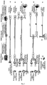
- Fig. 1 The basic principle of the access area of a telecommunications network according to the prior art is in Fig. 1 shown: For the fixed network area, the variants a) to d) can be assumed as examples. For access to the mobile network, variant e) is to describe the predominant technical solution.
- UPS systems electronic generators and batteries
- outdoor locations generally do not have full-fledged UPS systems consisting of generators and batteries for emergency power operation by the hour.
- Variant a represents the classic analogue telephone line (PSTN).
- DIV digital exchange
- the customer location is connected to a port of the DIV via a copper double-core cable and terminated with a network termination box (TAE, telecommunications termination unit).
- TAE network termination box
- TAE network termination box
- a corded telephone is connected to the TAE in the customer location, it will be remotely powered by the DIV via the copper pair in the event of a power failure. It is still possible to make phone calls in this case.
- This variant also applies mutatis mutandis to a digital telephone connection (ISDN - Integrated Services Digital Network) with a wired ISDN telephone.
- ISDN - Integrated Services Digital Network
- a modern radio base station for example with various comfort functions such as answering machine, telephone charging station, house call
- the phone handset is battery powered and would work for a few hours / days in case of power failure.
- the base station is generally connected to the normal 230 V AC power supply and is not battery-backed (and usually also no backup generator is present), in the case of power failure, the phone or the emergency call will not be possible.
- variant c) has established itself as a typical connection for telephony and broadband internet access.
- the xDSL broadband signal of the DSLAM (with connection to the Internet) in the operating point via a splitter on the copper double core coupled.
- PSTN telephony signals
- xDSL broadband Internet data
- PSTN telephony signals
- xDSL broadband Internet data
- the distance to be bridged to the customer location is shortened by placing the active network elements (eg DSLAMs) and the splitter in outdoor locations, e.g. B. in cable splitters, KVz in VDSL technology (Very high speed DSL).
- the DSLAM is connected by fiber to a switch in the office.
- This arrangement is shown in variant d).
- the telephony terminal used is authoritative. If, as shown, a DECT base station is used with connected radio telephones, telephoning or emergency call is not possible. If a wired telephone, similar to variant a) is connected to the TAE, telephoning is still possible.
- Variant e represents the state of the art for a mobile radio connection.
- mobile radio base stations are set up at suitable (corresponding to a high network coverage) external locations and connected by means of glass fiber to a switch in the operating point.
- These outdoor locations have power connections for the active technology, which, in general - d. H. not at all locations - but have no UPS systems (batteries, generators).
- UPS systems batteries, generators.
- the customer logs on with his terminal (mobile phones, smartphones) by logging into the mobile base station in the mobile network and can make calls anywhere. In the event of a local power failure, the mobile base station concerned (or several in a region affected by the power failure) will lose contact with all the terminals logged in there.
- the telephone service is transmitted via the then all-IP network, then external locations are used which operate according to the prior art without UPS systems, ie do not function in the event of a failure of the power supply in the relevant area:
- the mobile base station in question (or several in a region affected by the power failure) will lose contact with all the user equipment (UE) logged in there. There is no service available, thus no telephone emergency call deductible.
- the UEs can still bridge a certain amount of time in the individual devices and continue to function independently of the power supply.
- the access multiplexer located in the external area e.g. B. DSLAM in a KVz or in a building at FTTB (Fiber to the Building) - or more in a region affected by the power failure - inoperable and it is according to the prior art no communication from the connected terminals - typically home network router with the underlying Customer terminals (eg telephone, computer, laptop, network attached storage, tablet) - with the network more possible and thus in particular no telephone emergency call deductible.
- the landline terminals - unlike the UE in mobile (see above) - also have no battery backup, so that they - if in the customer location also the power supply breaks down - are immediately de-energized and thus inoperative.
- the network elements housed in operating stations are, as described in the prior art, supplied by UPS systems in case of failure of the power grid and remain - even in a consolidated All-IP network - functional.
- the object underlying the present invention is to provide a method and an apparatus which, for a given arrangement, such as an active home telephone network (DECT base station), enables to secure an emergency call service in the event of a power failure.
- DECT base station active home telephone network
- the present invention provides a method for efficiently providing emergency call functionality in the event of a power failure in telecommunications networks having at least one active remote site.
- the at least one outdoor location has at least one battery backup and / or a system for uninterruptible power supply for emergency power operation.
- the method comprises the steps of: (i) detecting a failure of the electric power supply; (ii) switching the active outdoor location to the emergency power mode and to an emergency call mode due to the failure of the electric power supply detected in step (i); and (iii) sending a message to connected terminals that a failure of the electrical power supply has been detected and / or the active remote site is switching to an emergency call mode of operation.
- the at least one active outside location has a DECT base station and / or a home gateway and / or a mobile radio base station and / or a landline node in an all-IP fixed network.
- DECT base station and home gateway are to be understood as active technology elements of the home network. They can also be used as a generalization of the approach active outdoor locations are interpreted. However, they are not present at active outside locations of the operator network (such as at the location of a mobile base station).
- the method additionally includes the steps of: (i) reporting the failure of the electrical power supply to a network and / or network controller connected to the remote site; and then (ii) switching to an emergency operation.
- the switching to the emergency mode can be delayed in time by a predetermined time t 1 after switching to the emergency power operation and / or a connection with the terminal, in particular a telephone call can be maintained for a certain time t 1 after switching to emergency operation.
- Another option is to send a message to the respective terminals that a failure of the electric power supply has been detected and / or the outdoor location switches to the emergency call mode after expiration of the predetermined time t 1 .
- the message sent to the respective terminals signals to the user that a DECT radio link is switched off and a DECT handset is to be plugged into a DECT base station in order to use it like a wired landline telephone for issuing an emergency call can be.
- switching to the emergency mode of operation includes turning off a DECT radio link and switching both a DECT handset and a DECT base station to a low power mode and / or inhibiting the use of broadband devices and restricting usage Emergency calls, especially voice calls.
- the method comprises: (i) detecting a failure of the electrical power supply of an active outdoor location and / or a failure of the local electrical power supply by the connected device with network termination function; (ii) switching to a narrowband mode with local electrical power supply in place, while still allowing the LAN to be used but only allowing emergency calls to the outside location; or (iii) switch to an emergency mode when the local power supply is interrupted, with all auxiliary functions of the connected unit with network termination function switched off and only emergency calls are possible directly on the device.
- a terminal connected device with network termination function is equipped with an emergency call button and possibly with a microphone and speakers.
- a terminal is provided in connection with a mobile emergency button that can be worn on the person to make an emergency call at any time.
- the mobile emergency button could be a radio transmission o.ä. over short distance (within the apartment) of this mobile device to z. B. Connect the home network router.
- the method additionally comprises the steps of: (i) detecting whether a plurality of terminals, such as mobile phones and / or landline telephones, are located at the same location and connected to the remote site, and (ii) decide that only one device, e.g. a mobile phone or a landline phone is provided to the emergency mode of operation and other devices can be completely turned off.
- a plurality of terminals such as mobile phones and / or landline telephones
- an apparatus for efficiently providing emergency call functionality in telecommunication networks having at least one active remote site equipped with at least one battery backup and / or an uninterruptible power supply facility in the event of power failure using the previously described method.
- a battery buffering - or possibly additionally a hedging with diesel generator - (UPS system) remote remote sites can be cost-effective because the proposed method exclusively uses low power mode operating modes in the event of power failure for the emergency call service.
- the duration of the emergency call is increased by the inventive use of the low power modes during emergency operation (compared to normal operation).
- an emergency call option is created for the fixed network operation by a separate emergency button is attached, which provides an emergency call via the fixed network together with the now also to be installed battery backup for the home network router.
- the handset When operating DECT telephones in the home network, the handset is firmly connected to the DECT base station via a cable connection (eg charging cable / charging cradle) and thus the emergency call functionality is enabled, as with a permanently connected telephone of conventional design with remote-fed emergency call functionality.
- a cable connection eg charging cable / charging cradle
- the method and the device according to the present invention description a way to ensure this Notruffunktion gleich in case of power failure both in a conventional network (which consists of separate shares for telephony and broadband) and - and above all - in a consolidated All-IP telecommunications network.
- the method is also applicable to today's networks that have not yet migrated to an all-IP network to ensure emergency call functionality in the event of a power grid failure.
- DECT base stations and home network routers which are usually not protected by UPS systems and therefore do not enable emergency call operation in the event of a power failure, can also be considered active outside locations. If remote external locations already have UPS systems, then the method according to the invention allows a longer maintenance of the emergency call functionality compared to normal operation.
- the utility of the present invention thus exists on two sides: For the network operator, it offers the advantage of a continuous emergency call operation even in the event of a power failure in networks containing active external locations.
- FIG Fig. 2 The underlying arrangement of the invention is shown schematically in FIG Fig. 2 shown.
- the principle is based on the fact that the active external locations of the telecommunications network (DECT base stations, mobile remote sites, fixed network access multiplexer) with UPS facilities (batteries or accumulators) are properly equipped, so that the active network technology at these outdoor sites a period of time (on the order from, for example, a few hours) to provide the emergency call service under today's or all-IP network conditions.
- DECT base station and home gateway are to be understood as active technology elements of the home network. They can also be interpreted as active external locations in the sense of a generalization of the approach. However, they are not present at active outside locations of the operator network (such as at the location of a mobile base station).
- UPS Since then a variety of locations is equipped with this UPS technology, it is advantageous that these UPS systems can be provided very inexpensively. In order to achieve this goal, it is again favorable to install the lowest possible battery / battery capacity.
- the power requirement of the active technology in the outdoor locations is reduced to a minimum in the event of an accident and the required bridging time is achieved with the lowest possible battery / battery capacity and minimum costs.
- the active technique in the sense of last-adaptive operation must be operated in suitable low-bit-rate modes in order to minimize its power consumption.
- the network node in the outdoor location is put into a "breakdown mode" (emergency call mode): It is preferably signaled in the direction of the network (buffered by UPS systems in the stations anyway) and the network controller that such a failure of the power supply present and the affected Network node is switched to the appropriate mode.
- a breakdown mode (emergency call mode): It is preferably signaled in the direction of the network (buffered by UPS systems in the stations anyway) and the network controller that such a failure of the power supply present and the affected Network node is switched to the appropriate mode.
- low power mode lower power consumption
- It may be z. B. may be parts of an aggregation or core network.
- the connected endpoints are also informed via signaling.
- the outside node now places all connections to the end nodes in the narrowband emergency mode, in which connectivity to the network is maintained for emergency purposes (eg, only emergency telephone traffic) with the least possible power consumption.
- the outer node itself is now in a low power mode and remains there until either the power supply re-enters - or until the battery / battery capacity is exhausted. If the energy supply of the outside location is functioning again, then the respective node is returned to the normal operating mode in an orderly manner. Accordingly, the connected endpoints (terminals) are informed by signaling and also switched to normal operation. At the same time, preferably, a corresponding signaling in the network and in the direction of network control that normal operation is present.
- this method can be used if locally and / or regionally the power supply fails and thus one and / or several outdoor locations are affected.
- convergent network can also be determined across the fixed network and mobile network, whether a mobile terminal is located locally in the same position as an associated fixed network connection: Then it is possible here to provide only one emergency call to performance and thus To conserve battery / battery capacity and to use the available capacity to maintain as many potential emergency calls as possible. This will be described in more detail below with reference to a fourth embodiment.
- the DECT base station equipped with a battery to run the inventive method for the emergency call to can.
- the DECT base station is considered an active outdoor location.
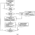
- the principle of operation of the method is based on the in Fig. 3 described two arrangements described.
- the arrangement a) shows a solution for a wireless DECT base station, which is equipped with a battery buffering to ensure the emergency call functionality in case of power failure.
- a home gateway which contains the DECT functionality and is provided in a corresponding manner with a battery buffering.
- a message will be sent to all handsets via the "emergency call mode".
- the DECT connection on base station side and handset side is switched off.
- an emergency call operation via the handset, which is plugged into the charging base of the base station or connected via a charging cable to the base station and the power supply via a built-in battery is possible.
- the emergency mode can be indicated by eg a flashing LED on the DECT base station and the handset. It is then further checked whether the external power supply is available again. If this is the case, the system switches to normal operation. Otherwise the emergency call operation is maintained.
- the DECT handset (or DECT handset) has its own battery and the DECT base station is equipped according to the invention. An announcement is made that the DECT radio connection is switched off and that the DECT handset is to be plugged into the DECT base station. Then the DECT radio link is turned off to put both the handset and the base station in a low-power (emergency call) mode.
- the inserted into the base station DECT handset can also be used as a wired landline telephone as variant a) in Fig. 2 be used. Handset battery and base station battery provide power to the DECT handset.
- z. B. an LED be displayed that emergency call operation is present.
- the emergency mode is in variant b) the Fig. 3 no use of the broadband devices (eg PC, laptop) possible; only the connection over the telephone channel is supported in the emergency call mode.
- Fig. 2 shows in variant e) and in the same manner Fig. 6 , Variant d) an embodiment 2 of the present invention for a mobile network with active technology in outdoor locations.
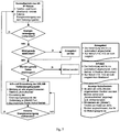
- a corresponding info text is sent. For example, this could read: "the connection will automatically shut down in x seconds and only emergency calls will be possible”. If no data is transmitted or after info text has been sent and elapsed x seconds, a message is sent to all handsets via the "emergency call mode". In addition, throttling of the mobile radio connection (transmission capacity) is initiated on the base station side and only low-power emergency call operation is permitted. At the same time the booked mobile phones indicate the "emergency power operation", eg by a flashing LED. It is then further checked whether the external power supply may be available again. If this is the case, the system switches to normal operation. Otherwise, the "emergency power operation" is maintained.
- the mobile node at the remote site detects a power failure.
- BS becomes synonymous with the active mobile node at Outdoor location used.
- the BS signals to the network and the network controller that it has detected a power failure and now switches to disaster mode, ie emergency mode, in which only emergency telephone traffic is possible.
- the BS informs all registered UEs that only emergency operation is possible.
- the BS is reconfigured so that only voice calls are possible and moves into a narrowband mode that enables the emergency service and requires minimal power (low power mode).
- the BS needs so little battery backup (battery capacity).
- UE also switches to an emergency mode of operation (e.g., broadband services UMTS, EDGE, HSPA, WLAN, GPS, etc.
- an emergency mode of operation e.g., broadband services UMTS, EDGE, HSPA, WLAN, GPS, etc.
- the BS is equipped with a battery / battery backup.
- the UE have a power supply network that is at least temporarily independent of the energy supply network in the form of the battery, which on average allows operation for a certain period of time.
- FIG. 3 shows the embodiment 3 according to the present invention, based on an active all-IP fixed network in remote locations (in the variants FTTEx, FTTCab, FTTB; s. Fig. 6 a) to c) ).
- the optical fiber is routed to the KVz (FTTCab, b)) and from there the broadband signal is transmitted from the VDSL-DSLAM installed there via copper two-wire cable.
- the invention can be used mutatis mutandis, when the glass fiber is further guided in the direction of the customer and z.
- DP drop point
- FTTB, c building
- a corresponding info text is sent. This could be eg: "the connection will be switched off automatically in x seconds and only emergency calls will be possible” or for the UPS operation: "computer goes down”. If no data is transmitted or after info text has been sent and elapsed x seconds, a message is sent to all connected telephones via the "emergency call mode". In addition, a throttling of the transmission capacity of the connection per DSLAM port is initiated and only low-power emergency call operation is possible. At the same time, "emergency power operation” can be displayed on all devices registered with the xDSL modem and the modem itself, eg by a flashing LED.
- At least one (“master”) telephone suitable for emergency calls can be connected by cable to the xDSL modem and used for emergency calls. It is then further checked whether the external power supply may be available again. If this is the case, the system switches to normal operation. Otherwise, the "emergency call mode" is maintained.
- This emergency call functionality on the home network router can be expanded to include an emergency button worn on a person to send an emergency call even in the case of sudden emergencies where the way to the home network router is no longer possible.
- the mobile emergency button could be a radio transmission o.ä. over short distance (within the apartment) of this mobile device to z. B. Connect the home network router.
- An additional extension is the arrangement (according to embodiment 1) by the DECT handset is connected via a cable to the base station or plugged into the base station and thus works like a wired landline phone.
- the ZM is equipped with a battery / battery backup.
- a battery backup of the home network router is provided, which does not exist according to the prior art.
- the home network router according to the invention with the described emergency call equipment (key, microphone, speakers) equip. If the integrated battery reaches a critical state of charge, it is necessary to signal the user that this must be replaced (eg similar to the usual technology for smoke detectors).
- the home network router is to be understood here as an example of a device that provides a customer network termination (network termination, NT).
- network termination network termination
- this feature is integrated into a device with other features (for example, routing in the home network, possibly storage). In general, however, this can also be done separately (separate NT and separate routers and terminals). Only one terminal without this NT function would not be sufficient here (because somewhere between the active external location of the network and the terminal, the said NT function must be realized).
- the method for this embodiment 4 works in principle analogous to those in the Previous Embodiments 2 and 3 described method. However, it is now additionally checked whether, if necessary, mobile phones are located in the same place as a landline. This is z. B. then practically relevant if there are several people in a family with their UEs (mobile phones) in their apartment, which also contains a landline. In order to determine this, preferably a central control entity (ZSI) is provided which maintains this information, e.g. In a data center (the "cloud"). If it is determined that the above case has occurred, only one emergency call channel is needed, eg. B. over the fixed net.
- ZSI central control entity
- the mobile phones are deregistered by the base station and the power available to the base station and now saved can be used for a longer period of power outage.
- the decision can turn out the other way around, so switching off the landline and "holding open” a mobile connection.
- This decision is preferably achieved by means of an optimization that performs the ZSI with the objective function of the longest possible breakdown operation of the entire network in the affected area.
- a convergent network which consists of an all-IP landline and a mobile network.
- the ZSI is included, which can reside in the cloud (in a data center) and the coordination of the inter-fixed and mobile network overall process in the event of an accident takes over, in the form of a flowchart in Fig. 9 will be shown.
- a location signaling of the mobile radio terminals is initiated to a central control instance (mobile phones / smartphones in the home zone). Furthermore, it will be checked if the phone is being used. If this is the case, a corresponding announcement text, eg that the connection is automatically switched off in x seconds and that only emergency calls will be possible, is sent. If no telephone is currently being used or after the transmitted outgoing message and elapsed x seconds, further checks are made as to whether data is currently being transmitted. If this is the case, a corresponding info text is sent. This could be eg: "the connection will be switched off automatically in x seconds and only emergency calls will be possible" or for the UPS operation: "computer goes down”.
- the central tax authority can decide whether, for example, a landline telephone or a mobile phone is provided for the emergency call. The decision is made by the central tax authority, taking into account the optimization of network capacity. In addition, throttling of the transmission capacity of the connection per DSLAM port or in the mobile network is initiated and only low-power emergency call operation is allowed.
- the "emergency power operation” can be displayed on all devices registered with the xDSL modem, the modem itself and all mobile phones in the Home Zone, eg by a flashing LED.
- At least one (“master”) telephone suitable for emergency calls can be connected by cable to the xDSL modem or a mobile phone in the home zone (central control unit decision) can be used for emergency calls. It is then further checked whether the external power supply may be available again. If this is the case, the system switches to normal operation. Otherwise, the "emergency power operation" is maintained.
Landscapes
- Engineering & Computer Science (AREA)
- Signal Processing (AREA)
- Computer Networks & Wireless Communication (AREA)
- Telephonic Communication Services (AREA)
Claims (10)
- Procédé destiné à fournir de façon efficace une fonctionnalité d'appel d'urgence en cas de panne de l'alimentation en énergie électrique dans des réseaux de télécommunication, avec au moins une station de base DECT qui comporte au moins une pile tampon, avec les étapes suivantes réalisées par la station de base DECT :a) détection d'une panne de l'alimentation en énergie électrique de la station de base DECT au moins au nombre de un ;b) commutation de la station de base DECT vers le fonctionnement avec courant de secours et vers un mode de fonctionnement d'appel d'urgence en raison de la panne de l'alimentation en énergie électrique détectée dans l'étape a) ; etc) envoi d'un message à des terminaux connectés signalant qu'une panne de l'alimentation en énergie électrique de la station de base DECT au moins au nombre de un a été détectée et que la station de base DECT au moins au nombre de un commute dans un mode de fonctionnement d'appel d'urgence,la commutation vers le mode de fonctionnement d'appel d'urgence s'effectuant avec une temporisation d'une durée t1 prédéfinie après la commutation vers le fonctionnement avec courant de secours et une communication téléphonique étant maintenue pendant une certaine durée t1 après la commutation dans le fonctionnement avec courant de secours,
la liaison DECT vers le côté station de base et partie mobile étant coupée dans le mode de fonctionnement d'appel d'urgence, et un fonctionnement d'appel d'urgence étant possible par le biais d'une partie mobile DECT qui est enfichée dans le socle de charge de la station de base ou qui est raccordée à la station de base par le biais d'un câble de charge, et l'alimentation électrique étant possible par le biais d'une batterie intégrée. - Procédé selon la revendication 1, avec les étapes suivantes : signalement de la panne de l'alimentation en énergie électrique à un réseau et/ou à une commande de réseau qui est raccordé(e) à la station de base DECT ; et ensuite commutation vers un fonctionnement avec courant de secours.
- Procédé selon la revendication 1 ou 2, le message envoyé aux terminaux respectifs signalant à l'utilisateur qu'une liaison radio DECT est hors circuit / est mise hors circuit, et qu'une partie mobile DECT doit être enfichée dans une station de base DECT pour pouvoir être utilisée comme un téléphone de réseau fixe câblé pour effectuer un appel d'urgence.
- Procédé selon l'une des revendications 1 à 3, la commutation vers le mode de fonctionnement d'appel d'urgence comportant : mise hors circuit d'une liaison radio DECT et commutation vers un mode de puissance faible aussi bien de la partie mobile DECT que d'une station de base DECT.
- Procédé selon l'une des revendications 1 à 4, la commutation vers le mode de fonctionnement d'appel d'urgence comportant : empêchement de l'utilisation d'appareils à large bande et restriction de l'utilisation à des appels d'urgence, en particulier des appels d'urgence vocaux.
- Procédé selon l'une des revendications 1 à 5, le réseau de télécommunication disposant, avec au moins une station de base DECT, en plus d'au moins un appareil connecté côté extrémité avec fonction de terminaisons réseau, et le procédé comportant en outre :a) détection d'une panne de l'alimentation en énergie électrique de la station de base DECT au moins au nombre de un ;b) commutation vers un mode bande étroite en présence d'une alimentation en énergie électrique locale, le LAN pouvant continuer à être utilisé, mais seuls des appels d'urgence étant autorisés vers l'extérieur en direction de la station de base DECT au moins au nombre de un ; ouc) commutation vers un mode de fonctionnement d'appel d'urgence en cas d'interruption de l'alimentation en énergie électrique locale, toutes les fonctions supplémentaires de l'appareil connecté avec fonction de terminaison réseau étant mises hors circuit, et seuls des appels d'urgence étant possibles directement sur l'appareil,la commutation vers le mode de fonctionnement d'appel d'urgence s'effectuant avec une temporisation d'une durée t1 prédéfinie après la commutation vers le fonctionnement avec courant de secours, et une communication téléphonique étant maintenue pendant une certaine durée t1 après la commutation dans le fonctionnement avec courant de secours, et envoi d'un message aux terminaux respectifs signalant qu'une panne de l'alimentation en énergie électrique été détectée et que la station de base DECT au moins au nombre de un commute dans le mode de fonctionnement d'appel d'urgence après expiration de la durée t1 prédéfinie.
- Procédé selon l'une des revendications 1 à 6, un appareil connecté côté extrémité avec fonction de terminaison réseau étant équipé d'une touche d'appel d'urgence et éventuellement d'un microphone et d'un haut-parleur.
- Procédé selon l'une des revendications 1 à 7, un terminal en liaison avec un bouton d'appel d'urgence mobile qui peut être porté sur la personne étant fourni pour pouvoir effectuer à tout moment un appel d'urgence.
- Procédé selon l'une des revendications 1 à 8, avec les étapes suivantes :a) détection indiquant si plusieurs terminaux tels que des téléphones mobiles et/ou des téléphones fixes se trouvent dans un même endroit et sont raccordés à la station de base DECT, etb) décision spécifiant qu'un seul appareil, par exemple un téléphone mobile ou un téléphone fixe, est fourni pour le mode de fonctionnement d'appel d'urgence et que d'autres appareils peuvent être complètement mis hors circuit.
- Dispositif destiné à fournir de façon efficace une fonctionnalité d'appel d'urgence dans des réseaux de télécommunication, avec au moins une station de base DECT équipée d'au moins une pile tampon en cas de panne de l'alimentation en énergie électrique avec utilisation d'un procédé selon l'une des revendications de procédé 1 à 9.
Priority Applications (1)
| Application Number | Priority Date | Filing Date | Title |
|---|---|---|---|
| EP14157071.3A EP2913990B1 (fr) | 2014-02-27 | 2014-02-27 | Procédé et dispositif de mise à disposition efficace d'une fonctionnalité d'appel d'urgence dans une station de base DECT en cas de panne de l'alimentation en énergie électrique |
Applications Claiming Priority (1)
| Application Number | Priority Date | Filing Date | Title |
|---|---|---|---|
| EP14157071.3A EP2913990B1 (fr) | 2014-02-27 | 2014-02-27 | Procédé et dispositif de mise à disposition efficace d'une fonctionnalité d'appel d'urgence dans une station de base DECT en cas de panne de l'alimentation en énergie électrique |
Publications (2)
| Publication Number | Publication Date |
|---|---|
| EP2913990A1 EP2913990A1 (fr) | 2015-09-02 |
| EP2913990B1 true EP2913990B1 (fr) | 2019-04-10 |
Family
ID=50190296
Family Applications (1)
| Application Number | Title | Priority Date | Filing Date |
|---|---|---|---|
| EP14157071.3A Active EP2913990B1 (fr) | 2014-02-27 | 2014-02-27 | Procédé et dispositif de mise à disposition efficace d'une fonctionnalité d'appel d'urgence dans une station de base DECT en cas de panne de l'alimentation en énergie électrique |
Country Status (1)
| Country | Link |
|---|---|
| EP (1) | EP2913990B1 (fr) |
Family Cites Families (3)
| Publication number | Priority date | Publication date | Assignee | Title |
|---|---|---|---|---|
| WO1999031860A1 (fr) * | 1997-12-12 | 1999-06-24 | Thomson Licensing S.A. | Batterie de secours pour unite de base d'un reseau de telephonie sans fil |
| US7287175B2 (en) * | 2004-07-19 | 2007-10-23 | Tellabs Petaluma, Inc. | Optical network terminal with low-power sleep logic that substantially extends the life of the battery after the AC main power supply has been lost |
| EP2362626A1 (fr) * | 2010-02-15 | 2011-08-31 | British Telecommunications public limited company | Équipement téléphonique alimentant un noeud de réseau |
-
2014
- 2014-02-27 EP EP14157071.3A patent/EP2913990B1/fr active Active
Non-Patent Citations (1)
| Title |
|---|
| None * |
Also Published As
| Publication number | Publication date |
|---|---|
| EP2913990A1 (fr) | 2015-09-02 |
Similar Documents
| Publication | Publication Date | Title |
|---|---|---|
| DE60104064T2 (de) | Vorrichtung und Verfahren zur Bereitstellung von Leistungsnotdiensten für DSL-Teilnehmern | |
| DE69635322T2 (de) | Verfahren und Einrichtung zum Umschalten zwischen schnurlosem und zellularem Kommunikationssystem | |
| DE69331328T2 (de) | Verteilte gemeinsame hausinterne anlage, die mehreren fernsprechanbietern erlaubt den gleichen teilnehmer zu bedienen | |
| DE60026340T2 (de) | Anordnung und verfahren zur leistungsversorgung in einem kommmunikationsnetzwerk | |
| DE60035943T2 (de) | Voice-over-ip gateway | |
| CN105788036A (zh) | 一种基于3g/4g通信的无线门口机/围墙机 | |
| CN104038367A (zh) | 一种电力调度交换网络结构 | |
| DE69130230T2 (de) | Verfahren zur signalisierung/kommunikation in einem türsprechsystem und türsprechsystem zur kommunikation unter anwendung des verfahrens | |
| CN204068990U (zh) | 矿井有线、广播一体化调度通信系统 | |
| CN204060796U (zh) | 矿井广播、视频一体化调度通信系统 | |
| WO1996018274A1 (fr) | Systeme de communication a telephones mobiles et son procede d'exploitation | |
| DE68907756T2 (de) | Fernüberwachungsanordnung auf einem Fernsprechkanal für Einzel- oder Mehrzweck-Analogen. | |
| CN105163060A (zh) | 一种基于互联网的智能楼宇对讲系统及装置 | |
| EP2002677B1 (fr) | Procede pour un fonctionnement a faible consommation de courant de terminaux de communication dans un systeme de communication | |
| EP2913990A1 (fr) | Procédé et dispositif de mise à disposition efficace d'une fonctionnalité d'appel d'urgence dans des réseaux de clients et de télécommunications avec sites extérieurs actifs en cas de panne de l'alimentation en énergie électrique | |
| CN201282479Y (zh) | 一种软交换和ip承载网远程集中应急接入系统 | |
| CN213586074U (zh) | 视讯一体化调度系统 | |
| CN204089856U (zh) | 矿井有线、无线一体化调度通信系统 | |
| CN203911947U (zh) | 一种电力调度交换网络结构 | |
| CN204465725U (zh) | 基于标准通信协议的可视对讲门禁系统 | |
| DE10306113B4 (de) | System mit einem Motorschutzstecker mit integrierter Vorrichtung zum Erfassen und drahtlosen Übermitteln von Fehlerzuständen | |
| DE102011055741A1 (de) | Kommunikationsgerät für eine Kommunikationsanlage | |
| CN216774793U (zh) | 一种主备扩容调度通信系统 | |
| EP2381655B1 (fr) | Dispositif de communication | |
| CN220210491U (zh) | 一种电力调度电话系统远程延伸平台 |
Legal Events
| Date | Code | Title | Description |
|---|---|---|---|
| PUAI | Public reference made under article 153(3) epc to a published international application that has entered the european phase |
Free format text: ORIGINAL CODE: 0009012 |
|
| AK | Designated contracting states |
Kind code of ref document: A1 Designated state(s): AL AT BE BG CH CY CZ DE DK EE ES FI FR GB GR HR HU IE IS IT LI LT LU LV MC MK MT NL NO PL PT RO RS SE SI SK SM TR |
|
| AX | Request for extension of the european patent |
Extension state: BA ME |
|
| 17P | Request for examination filed |
Effective date: 20160301 |
|
| RBV | Designated contracting states (corrected) |
Designated state(s): AL AT BE BG CH CY CZ DE DK EE ES FI FR GB GR HR HU IE IS IT LI LT LU LV MC MK MT NL NO PL PT RO RS SE SI SK SM TR |
|
| STAA | Information on the status of an ep patent application or granted ep patent |
Free format text: STATUS: EXAMINATION IS IN PROGRESS |
|
| 17Q | First examination report despatched |
Effective date: 20180516 |
|
| GRAP | Despatch of communication of intention to grant a patent |
Free format text: ORIGINAL CODE: EPIDOSNIGR1 |
|
| STAA | Information on the status of an ep patent application or granted ep patent |
Free format text: STATUS: GRANT OF PATENT IS INTENDED |
|
| RIC1 | Information provided on ipc code assigned before grant |
Ipc: H04M 19/08 20060101ALI20180907BHEP Ipc: H04M 1/725 20060101AFI20180907BHEP |
|
| INTG | Intention to grant announced |
Effective date: 20181001 |
|
| GRAS | Grant fee paid |
Free format text: ORIGINAL CODE: EPIDOSNIGR3 |
|
| GRAA | (expected) grant |
Free format text: ORIGINAL CODE: 0009210 |
|
| STAA | Information on the status of an ep patent application or granted ep patent |
Free format text: STATUS: THE PATENT HAS BEEN GRANTED |
|
| AK | Designated contracting states |
Kind code of ref document: B1 Designated state(s): AL AT BE BG CH CY CZ DE DK EE ES FI FR GB GR HR HU IE IS IT LI LT LU LV MC MK MT NL NO PL PT RO RS SE SI SK SM TR |
|
| REG | Reference to a national code |
Ref country code: GB Ref legal event code: FG4D Free format text: NOT ENGLISH |
|
| REG | Reference to a national code |
Ref country code: CH Ref legal event code: EP Ref country code: AT Ref legal event code: REF Ref document number: 1120281 Country of ref document: AT Kind code of ref document: T Effective date: 20190415 |
|
| REG | Reference to a national code |
Ref country code: IE Ref legal event code: FG4D Free format text: LANGUAGE OF EP DOCUMENT: GERMAN |
|
| REG | Reference to a national code |
Ref country code: DE Ref legal event code: R096 Ref document number: 502014011358 Country of ref document: DE |
|
| REG | Reference to a national code |
Ref country code: NL Ref legal event code: MP Effective date: 20190410 |
|
| REG | Reference to a national code |
Ref country code: LT Ref legal event code: MG4D |
|
| PG25 | Lapsed in a contracting state [announced via postgrant information from national office to epo] |
Ref country code: NL Free format text: LAPSE BECAUSE OF FAILURE TO SUBMIT A TRANSLATION OF THE DESCRIPTION OR TO PAY THE FEE WITHIN THE PRESCRIBED TIME-LIMIT Effective date: 20190410 |
|
| PG25 | Lapsed in a contracting state [announced via postgrant information from national office to epo] |
Ref country code: ES Free format text: LAPSE BECAUSE OF FAILURE TO SUBMIT A TRANSLATION OF THE DESCRIPTION OR TO PAY THE FEE WITHIN THE PRESCRIBED TIME-LIMIT Effective date: 20190410 Ref country code: LT Free format text: LAPSE BECAUSE OF FAILURE TO SUBMIT A TRANSLATION OF THE DESCRIPTION OR TO PAY THE FEE WITHIN THE PRESCRIBED TIME-LIMIT Effective date: 20190410 Ref country code: NO Free format text: LAPSE BECAUSE OF FAILURE TO SUBMIT A TRANSLATION OF THE DESCRIPTION OR TO PAY THE FEE WITHIN THE PRESCRIBED TIME-LIMIT Effective date: 20190710 Ref country code: FI Free format text: LAPSE BECAUSE OF FAILURE TO SUBMIT A TRANSLATION OF THE DESCRIPTION OR TO PAY THE FEE WITHIN THE PRESCRIBED TIME-LIMIT Effective date: 20190410 Ref country code: HR Free format text: LAPSE BECAUSE OF FAILURE TO SUBMIT A TRANSLATION OF THE DESCRIPTION OR TO PAY THE FEE WITHIN THE PRESCRIBED TIME-LIMIT Effective date: 20190410 Ref country code: PT Free format text: LAPSE BECAUSE OF FAILURE TO SUBMIT A TRANSLATION OF THE DESCRIPTION OR TO PAY THE FEE WITHIN THE PRESCRIBED TIME-LIMIT Effective date: 20190910 Ref country code: SE Free format text: LAPSE BECAUSE OF FAILURE TO SUBMIT A TRANSLATION OF THE DESCRIPTION OR TO PAY THE FEE WITHIN THE PRESCRIBED TIME-LIMIT Effective date: 20190410 Ref country code: AL Free format text: LAPSE BECAUSE OF FAILURE TO SUBMIT A TRANSLATION OF THE DESCRIPTION OR TO PAY THE FEE WITHIN THE PRESCRIBED TIME-LIMIT Effective date: 20190410 |
|
| PG25 | Lapsed in a contracting state [announced via postgrant information from national office to epo] |
Ref country code: RS Free format text: LAPSE BECAUSE OF FAILURE TO SUBMIT A TRANSLATION OF THE DESCRIPTION OR TO PAY THE FEE WITHIN THE PRESCRIBED TIME-LIMIT Effective date: 20190410 Ref country code: PL Free format text: LAPSE BECAUSE OF FAILURE TO SUBMIT A TRANSLATION OF THE DESCRIPTION OR TO PAY THE FEE WITHIN THE PRESCRIBED TIME-LIMIT Effective date: 20190410 Ref country code: LV Free format text: LAPSE BECAUSE OF FAILURE TO SUBMIT A TRANSLATION OF THE DESCRIPTION OR TO PAY THE FEE WITHIN THE PRESCRIBED TIME-LIMIT Effective date: 20190410 Ref country code: GR Free format text: LAPSE BECAUSE OF FAILURE TO SUBMIT A TRANSLATION OF THE DESCRIPTION OR TO PAY THE FEE WITHIN THE PRESCRIBED TIME-LIMIT Effective date: 20190711 Ref country code: BG Free format text: LAPSE BECAUSE OF FAILURE TO SUBMIT A TRANSLATION OF THE DESCRIPTION OR TO PAY THE FEE WITHIN THE PRESCRIBED TIME-LIMIT Effective date: 20190710 |
|
| PG25 | Lapsed in a contracting state [announced via postgrant information from national office to epo] |
Ref country code: IS Free format text: LAPSE BECAUSE OF FAILURE TO SUBMIT A TRANSLATION OF THE DESCRIPTION OR TO PAY THE FEE WITHIN THE PRESCRIBED TIME-LIMIT Effective date: 20190810 |
|
| REG | Reference to a national code |
Ref country code: DE Ref legal event code: R097 Ref document number: 502014011358 Country of ref document: DE |
|
| PG25 | Lapsed in a contracting state [announced via postgrant information from national office to epo] |
Ref country code: SK Free format text: LAPSE BECAUSE OF FAILURE TO SUBMIT A TRANSLATION OF THE DESCRIPTION OR TO PAY THE FEE WITHIN THE PRESCRIBED TIME-LIMIT Effective date: 20190410 Ref country code: CZ Free format text: LAPSE BECAUSE OF FAILURE TO SUBMIT A TRANSLATION OF THE DESCRIPTION OR TO PAY THE FEE WITHIN THE PRESCRIBED TIME-LIMIT Effective date: 20190410 Ref country code: RO Free format text: LAPSE BECAUSE OF FAILURE TO SUBMIT A TRANSLATION OF THE DESCRIPTION OR TO PAY THE FEE WITHIN THE PRESCRIBED TIME-LIMIT Effective date: 20190410 Ref country code: EE Free format text: LAPSE BECAUSE OF FAILURE TO SUBMIT A TRANSLATION OF THE DESCRIPTION OR TO PAY THE FEE WITHIN THE PRESCRIBED TIME-LIMIT Effective date: 20190410 Ref country code: DK Free format text: LAPSE BECAUSE OF FAILURE TO SUBMIT A TRANSLATION OF THE DESCRIPTION OR TO PAY THE FEE WITHIN THE PRESCRIBED TIME-LIMIT Effective date: 20190410 |
|
| PLBE | No opposition filed within time limit |
Free format text: ORIGINAL CODE: 0009261 |
|
| STAA | Information on the status of an ep patent application or granted ep patent |
Free format text: STATUS: NO OPPOSITION FILED WITHIN TIME LIMIT |
|
| PG25 | Lapsed in a contracting state [announced via postgrant information from national office to epo] |
Ref country code: IT Free format text: LAPSE BECAUSE OF FAILURE TO SUBMIT A TRANSLATION OF THE DESCRIPTION OR TO PAY THE FEE WITHIN THE PRESCRIBED TIME-LIMIT Effective date: 20190410 Ref country code: SM Free format text: LAPSE BECAUSE OF FAILURE TO SUBMIT A TRANSLATION OF THE DESCRIPTION OR TO PAY THE FEE WITHIN THE PRESCRIBED TIME-LIMIT Effective date: 20190410 |
|
| 26N | No opposition filed |
Effective date: 20200113 |
|
| PG25 | Lapsed in a contracting state [announced via postgrant information from national office to epo] |
Ref country code: TR Free format text: LAPSE BECAUSE OF FAILURE TO SUBMIT A TRANSLATION OF THE DESCRIPTION OR TO PAY THE FEE WITHIN THE PRESCRIBED TIME-LIMIT Effective date: 20190410 |
|
| PG25 | Lapsed in a contracting state [announced via postgrant information from national office to epo] |
Ref country code: SI Free format text: LAPSE BECAUSE OF FAILURE TO SUBMIT A TRANSLATION OF THE DESCRIPTION OR TO PAY THE FEE WITHIN THE PRESCRIBED TIME-LIMIT Effective date: 20190410 |
|
| REG | Reference to a national code |
Ref country code: CH Ref legal event code: PL |
|
| REG | Reference to a national code |
Ref country code: BE Ref legal event code: MM Effective date: 20200229 |
|
| PG25 | Lapsed in a contracting state [announced via postgrant information from national office to epo] |
Ref country code: MC Free format text: LAPSE BECAUSE OF FAILURE TO SUBMIT A TRANSLATION OF THE DESCRIPTION OR TO PAY THE FEE WITHIN THE PRESCRIBED TIME-LIMIT Effective date: 20190410 Ref country code: LU Free format text: LAPSE BECAUSE OF NON-PAYMENT OF DUE FEES Effective date: 20200227 |
|
| PG25 | Lapsed in a contracting state [announced via postgrant information from national office to epo] |
Ref country code: CH Free format text: LAPSE BECAUSE OF NON-PAYMENT OF DUE FEES Effective date: 20200229 Ref country code: LI Free format text: LAPSE BECAUSE OF NON-PAYMENT OF DUE FEES Effective date: 20200229 |
|
| PG25 | Lapsed in a contracting state [announced via postgrant information from national office to epo] |
Ref country code: IE Free format text: LAPSE BECAUSE OF NON-PAYMENT OF DUE FEES Effective date: 20200227 |
|
| PG25 | Lapsed in a contracting state [announced via postgrant information from national office to epo] |
Ref country code: BE Free format text: LAPSE BECAUSE OF NON-PAYMENT OF DUE FEES Effective date: 20200229 |
|
| REG | Reference to a national code |
Ref country code: AT Ref legal event code: MM01 Ref document number: 1120281 Country of ref document: AT Kind code of ref document: T Effective date: 20200227 |
|
| PG25 | Lapsed in a contracting state [announced via postgrant information from national office to epo] |
Ref country code: AT Free format text: LAPSE BECAUSE OF NON-PAYMENT OF DUE FEES Effective date: 20200227 |
|
| PG25 | Lapsed in a contracting state [announced via postgrant information from national office to epo] |
Ref country code: MT Free format text: LAPSE BECAUSE OF FAILURE TO SUBMIT A TRANSLATION OF THE DESCRIPTION OR TO PAY THE FEE WITHIN THE PRESCRIBED TIME-LIMIT Effective date: 20190410 Ref country code: CY Free format text: LAPSE BECAUSE OF FAILURE TO SUBMIT A TRANSLATION OF THE DESCRIPTION OR TO PAY THE FEE WITHIN THE PRESCRIBED TIME-LIMIT Effective date: 20190410 |
|
| PG25 | Lapsed in a contracting state [announced via postgrant information from national office to epo] |
Ref country code: MK Free format text: LAPSE BECAUSE OF FAILURE TO SUBMIT A TRANSLATION OF THE DESCRIPTION OR TO PAY THE FEE WITHIN THE PRESCRIBED TIME-LIMIT Effective date: 20190410 |
|
| PGFP | Annual fee paid to national office [announced via postgrant information from national office to epo] |
Ref country code: GB Payment date: 20260219 Year of fee payment: 13 |
|
| PGFP | Annual fee paid to national office [announced via postgrant information from national office to epo] |
Ref country code: DE Payment date: 20260217 Year of fee payment: 13 |
|
| PGFP | Annual fee paid to national office [announced via postgrant information from national office to epo] |
Ref country code: FR Payment date: 20260223 Year of fee payment: 13 |