EP2914076A2 - Convertisseur de puissance et véhicule à moteur - Google Patents
Convertisseur de puissance et véhicule à moteur Download PDFInfo
- Publication number
- EP2914076A2 EP2914076A2 EP15156891.2A EP15156891A EP2914076A2 EP 2914076 A2 EP2914076 A2 EP 2914076A2 EP 15156891 A EP15156891 A EP 15156891A EP 2914076 A2 EP2914076 A2 EP 2914076A2
- Authority
- EP
- European Patent Office
- Prior art keywords
- accommodation part
- circuit unit
- flow path
- path portion
- power converter
- Prior art date
- Legal status (The legal status is an assumption and is not a legal conclusion. Google has not performed a legal analysis and makes no representation as to the accuracy of the status listed.)
- Withdrawn
Links
Images


Classifications
-
- H—ELECTRICITY
- H05—ELECTRIC TECHNIQUES NOT OTHERWISE PROVIDED FOR
- H05K—PRINTED CIRCUITS; CASINGS OR CONSTRUCTIONAL DETAILS OF ELECTRIC APPARATUS; MANUFACTURE OF ASSEMBLAGES OF ELECTRICAL COMPONENTS
- H05K7/00—Constructional details common to different types of electric apparatus
- H05K7/20—Modifications to facilitate cooling, ventilating, or heating
- H05K7/2089—Modifications to facilitate cooling, ventilating, or heating for power electronics, e.g. for inverters for controlling motor
- H05K7/20927—Liquid coolant without phase change
-
- B—PERFORMING OPERATIONS; TRANSPORTING
- B60—VEHICLES IN GENERAL
- B60L—PROPULSION OF ELECTRICALLY-PROPELLED VEHICLES; SUPPLYING ELECTRIC POWER FOR AUXILIARY EQUIPMENT OF ELECTRICALLY-PROPELLED VEHICLES; ELECTRODYNAMIC BRAKE SYSTEMS FOR VEHICLES IN GENERAL; MAGNETIC SUSPENSION OR LEVITATION FOR VEHICLES; MONITORING OPERATING VARIABLES OF ELECTRICALLY-PROPELLED VEHICLES; ELECTRIC SAFETY DEVICES FOR ELECTRICALLY-PROPELLED VEHICLES
- B60L53/00—Methods of charging batteries, specially adapted for electric vehicles; Charging stations or on-board charging equipment therefor; Exchange of energy storage elements in electric vehicles
- B60L53/20—Methods of charging batteries, specially adapted for electric vehicles; Charging stations or on-board charging equipment therefor; Exchange of energy storage elements in electric vehicles characterised by converters located in the vehicle
- B60L53/24—Using the vehicle's propulsion converter for charging
-
- B—PERFORMING OPERATIONS; TRANSPORTING
- B60—VEHICLES IN GENERAL
- B60L—PROPULSION OF ELECTRICALLY-PROPELLED VEHICLES; SUPPLYING ELECTRIC POWER FOR AUXILIARY EQUIPMENT OF ELECTRICALLY-PROPELLED VEHICLES; ELECTRODYNAMIC BRAKE SYSTEMS FOR VEHICLES IN GENERAL; MAGNETIC SUSPENSION OR LEVITATION FOR VEHICLES; MONITORING OPERATING VARIABLES OF ELECTRICALLY-PROPELLED VEHICLES; ELECTRIC SAFETY DEVICES FOR ELECTRICALLY-PROPELLED VEHICLES
- B60L2240/00—Control parameters of input or output; Target parameters
- B60L2240/40—Drive Train control parameters
- B60L2240/52—Drive Train control parameters related to converters
- B60L2240/525—Temperature of converter or components thereof
-
- Y—GENERAL TAGGING OF NEW TECHNOLOGICAL DEVELOPMENTS; GENERAL TAGGING OF CROSS-SECTIONAL TECHNOLOGIES SPANNING OVER SEVERAL SECTIONS OF THE IPC; TECHNICAL SUBJECTS COVERED BY FORMER USPC CROSS-REFERENCE ART COLLECTIONS [XRACs] AND DIGESTS
- Y02—TECHNOLOGIES OR APPLICATIONS FOR MITIGATION OR ADAPTATION AGAINST CLIMATE CHANGE
- Y02T—CLIMATE CHANGE MITIGATION TECHNOLOGIES RELATED TO TRANSPORTATION
- Y02T10/00—Road transport of goods or passengers
- Y02T10/60—Other road transportation technologies with climate change mitigation effect
- Y02T10/70—Energy storage systems for electromobility, e.g. batteries
-
- Y—GENERAL TAGGING OF NEW TECHNOLOGICAL DEVELOPMENTS; GENERAL TAGGING OF CROSS-SECTIONAL TECHNOLOGIES SPANNING OVER SEVERAL SECTIONS OF THE IPC; TECHNICAL SUBJECTS COVERED BY FORMER USPC CROSS-REFERENCE ART COLLECTIONS [XRACs] AND DIGESTS
- Y02—TECHNOLOGIES OR APPLICATIONS FOR MITIGATION OR ADAPTATION AGAINST CLIMATE CHANGE
- Y02T—CLIMATE CHANGE MITIGATION TECHNOLOGIES RELATED TO TRANSPORTATION
- Y02T10/00—Road transport of goods or passengers
- Y02T10/60—Other road transportation technologies with climate change mitigation effect
- Y02T10/7072—Electromobility specific charging systems or methods for batteries, ultracapacitors, supercapacitors or double-layer capacitors
-
- Y—GENERAL TAGGING OF NEW TECHNOLOGICAL DEVELOPMENTS; GENERAL TAGGING OF CROSS-SECTIONAL TECHNOLOGIES SPANNING OVER SEVERAL SECTIONS OF THE IPC; TECHNICAL SUBJECTS COVERED BY FORMER USPC CROSS-REFERENCE ART COLLECTIONS [XRACs] AND DIGESTS
- Y02—TECHNOLOGIES OR APPLICATIONS FOR MITIGATION OR ADAPTATION AGAINST CLIMATE CHANGE
- Y02T—CLIMATE CHANGE MITIGATION TECHNOLOGIES RELATED TO TRANSPORTATION
- Y02T90/00—Enabling technologies or technologies with a potential or indirect contribution to GHG emissions mitigation
- Y02T90/10—Technologies relating to charging of electric vehicles
- Y02T90/14—Plug-in electric vehicles
Definitions
- An embodiment disclosed herein relates to a power converter and a motor vehicle.
- a power converter mounted to an electric vehicle, a hybrid motor vehicle or the like see, e.g., Japanese Patent No. 3031669 .
- An electric vehicle or the like is equipped with, e.g., an AC load such as a traction motor or the like and a DC load such as a headlight or the like.
- the power converter includes a DC-DC converter circuit unit for stepping up or stepping down a DC voltage supplied from, e.g., a battery, and supplying DC power to a DC load, and an inverter circuit unit for converting DC power to AC power and supplying the AC power to an AC load.
- a DC-DC converter circuit unit for stepping up or stepping down a DC voltage supplied from, e.g., a battery, and supplying DC power to a DC load
- an inverter circuit unit for converting DC power to AC power and supplying the AC power to an AC load.
- the inverter circuit unit and the DC-DC converter circuit unit generate heat during operation thereof.
- the respective circuit units are disposed so as to make contact with a case.
- the respective circuit units are cooled by circulating a cooling medium through a bottom plate portion of the case.
- an embodiment disclosed herein provides a power converter and a motor vehicle which are capable of efficiently and effectively cooling an inverter circuit unit and a DC-DC converter circuit unit.
- a power converter including: a DC-DC converter circuit unit configured to step up or step down a voltage of direct current power supplied from a power supply; an inverter circuit unit configured to convert direct current power supplied from the power supply to alternating current power; and a first flow path portion and a second flow path portion through which a cooling medium flows, wherein the first flow path portion is disposed between the DC-DC converter circuit unit and the inverter circuit unit, and wherein the second flow path portion is disposed at an opposite side of the inverter circuit unit from a side at which the first flow path portion is disposed.
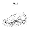
- Fig. 1 is a view showing a configuration example of a power converter and a motor vehicle according to an embodiment.
- Fig. 1 , Fig. 3A and the subsequent figures are schematic diagrams.
- a motor vehicle 1 includes a battery 3, an AC (alternating current) load 4, a DC (direct current) load 5 and a power converter 10.
- the motor vehicle 1 such as an electric vehicle, a hybrid motor vehicle or the like includes an electric motor (the AC load 4) (a traction motor to be described later) as a power source of a drive system.
- the battery 3 is a so-called a secondary battery which outputs DC power and supplies the DC power to the AC load 4 or the DC load 5 through the power converter 10 and which stores the regenerative power inputted through the power converter 10.
- the battery 3 corresponds to one example of a power supply.
- the AC load 4 is a device which is driven by the AC power supplied through the power converter 10.
- the AC load 4 may be a traction motor.
- the AC load 4 will be sometimes referred to as a "traction motor 4".
- the traction motor 4 is a power source of a drive system of the motor vehicle 1 and is configured by, e.g., an IPM motor (Interior Permanent Magnet Motor).
- IPM motor Interior Permanent Magnet Motor
- Fig. 1 there is illustrated a case where the drive type of the drive system is a front-wheel drive type. However, this is not intended to limit the drive type of the motor vehicle 1.
- the DC load 5 is a device which is driven by the low-voltage DC power supplied through the power converter 10.
- the DC load 5 may be, e.g., a headlight, an indoor lamp, a car audio, or a car navigation system.
- the DC load 5 is schematically shown as a single rectangular solid.
- the power converter 10 converts the DC power supplied from, e.g., the battery 3, to three-phase AC power and outputs the AC power to the traction motor 4. Furthermore, the power converter 10 steps down the voltage of the DC voltage and outputs the DC voltage to the DC load 5. Moreover, the power converter 10 returns the regenerative power generated during sudden deceleration of the traction motor 4 to the battery 3, thereby charging the battery 3. In case where the motor vehicle 1 is a hybrid motor vehicle, the power converter 10 charges the battery 3 with the electric power supplied from the traction motor 4 which serves as a generator during normal engine-driven running.
- Fig. 2 is a block diagram showing the configuration of the power converter 10.
- Typical components such as a current detector and the like are not shown.
- the power converter in accordance with the embodiment may include a DC-DC converter means and an inverter means.
- the DC-DC converter means and the inverter means may serve to change electrical characteristics of power supplied from a power supply.
- the power converter 10 illustrated in Fig. 2 includes a DC-DC converter circuit unit 31 and an inverter circuit unit 21 as examples of the DC-DC converter means and the inverter means.
- the power converter in accordance with the embodiment may further include a control means.
- the power converter 10 includes a control unit 22 as one example of the control means.
- the power converter 10 illustrated in Fig. 10 further includes a capacitor 20.
- the capacitor 20 is connected to the battery 3 and is configured to supply stable DC power to the inverter circuit unit 21.
- the inverter circuit unit 21 includes a power module 21a mounted with a switching element, e.g., an IGBT (Insulated Gate Bipolar Transistor) and a rectifying element, and a drive board 21b mounted with a drive circuit connected to the IGBT (see Fig. 5 ).
- a switching element e.g., an IGBT (Insulated Gate Bipolar Transistor) and a rectifying element
- a drive board 21b mounted with a drive circuit connected to the IGBT (see Fig. 5 ).
- the control unit 22 includes a control board mounted with a control circuit (not shown).
- the control circuit of the control unit 22 controls the IGBT of the power module 21a through the drive circuit of the inverter circuit unit 21.
- the inverter circuit unit 21 converts DC power to three-phase AC power and outputs the three-phase AC power to the traction motor 4.
- the DC-DC converter circuit unit 31 includes a converter module (not shown) mounted with a switching element, e.g., a MOSFET (Metal-Oxide-Semiconductor Field-Effect Transistor), a rectifying element and a voltage transformer, and a drive board (not shown) mounted with a drive circuit connected to the MOSFET.
- a switching element e.g., a MOSFET (Metal-Oxide-Semiconductor Field-Effect Transistor)
- a rectifying element and a voltage transformer e.g., a MOSFET (Metal-Oxide-Semiconductor Field-Effect Transistor)
- a drive board not shown mounted with a drive circuit connected to the MOSFET.
- the control circuit of the control unit 22 controls the MOSFET of the converter module through the drive circuit of the DC-DC converter circuit unit 31.
- the DC-DC converter circuit unit 31 steps down a voltage of the DC power with the voltage transformer and outputs the stepped-down DC power to the DC load 5.
- a vehicle control unit 6 for generally controlling the entire drive system of the motor vehicle 1 is connected to the control unit 22. Accordingly, the control unit 22 is controlled by the vehicle control unit 6.
- control unit 22 is configured to control both the inverter circuit unit 21 and the DC-DC converter circuit unit 31.
- present disclosure is not limited thereto.
- a converter control part may be provided independently of the control unit 22 such that the control unit 22 controls the inverter circuit unit 21 while the converter control part controls the DC-DC converter circuit unit 31.
- the DC-DC converter circuit unit 31 is configured to step down the voltage of the DC power.
- the present disclosure is not limited thereto.
- the DC-DC converter circuit unit 31 may be configured to step up the voltage of the DC power depending on the specifications of the DC load 5.
- the power module 21a of the inverter circuit unit 21 and the converter module of the DC-DC converter circuit unit 31 generate heat during operation thereof.
- the power module 21a of the inverter circuit unit 21 drives the traction motor 4 by controlling a large current. For that reason, the power module 21a generates a large amount of heat and tends to become relatively hot.
- the power converter 10 is configured to efficiently and effectively cool the inverter circuit unit 21 and the DC-DC converter circuit unit 31.
- the configuration of the power converter 10 will now be described in detail.
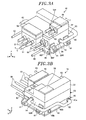
- Fig. 3A is a perspective view of the power converter 10.
- a three-dimensional rectangular coordinate system including a Z-axis whose positive direction extend vertically upward and whose negative direction extends vertically downward is sometimes indicated in the respective figures used in the following description.
- the Y-axis positive direction in the rectangular coordinate system is defined as the front side of the power converter 10.
- the X-axis positive direction is defined as the right side of the power converter 10.
- the X-axis negative side is defined as the left side of the power converter 10.
- Fig. 3B is a rear perspective view of the power converter 10 shown in Fig. 3A .
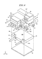
- Fig. 4 is an exploded perspective view of the power converter 10 shown in Fig. 3A .
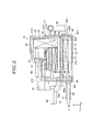
- Fig. 5 is a sectional view taken along line V-V in Fig. 3A .
- the power converter 10 includes a first accommodation part 40 and a second accommodation part 50.
- the first accommodation part 40 accommodates the DC-DC converter circuit unit 31 and so forth.
- the second accommodation part 50 accommodates the capacitor 20, the inverter circuit unit 21, the control unit 22 and so forth.
- the first accommodation part 40 corresponds to one example of a DC-DC converter accommodation part.
- the second accommodation part 50 corresponds to one example of an inverter accommodation part.
- Each of the first accommodation part 40 and the second accommodation part 50 is a casting formed into a rectangular solid shape or a substantially rectangular solid shape.
- the first accommodation part 40 and the second accommodation part 50 are unitarily coupled to each other.
- an upper surface (a first coupling surface) 40A of the first accommodation part 40 and a lower end 50A of the second accommodation part 50 are disposed so as to make contact with each other and are fixed and coupled to each other by fixing members (e.g., bolts) (not shown).
- fixing members e.g., bolts
- a first opening portion 41 is formed on a lower surface 40D of the first accommodation part 40.
- a first cover 42 is attached to the first opening portion 41. This makes it possible to prevent dust or water from entering the internal space of the first accommodation part 40 which accommodates the DC-DC converter circuit unit 31 and so forth.
- a second opening portion 512 is formed on an upper surface of the second accommodation part 50.
- a third opening portion 513 is formed on a lower surface (a second coupling surface) 50D of the second accommodation part 50.
- a second cover 52 is attached to the second opening portion 512.
- the third opening portion 513 is closed by the upper surface 40A of the first accommodation part 40. This makes it possible to prevent dust or water from entering the internal space of the second accommodation part 50 which accommodates the inverter circuit unit 21 and so forth.
- the power converter in accordance with the embodiment may further include a first cooling means and a second cooling means for cooling the DC-DC converter means and the inverter means (e.g., the DC-DC converter circuit unit 31 and the inverter circuit unit 21).
- a first cooling means and a second cooling means for cooling the DC-DC converter means and the inverter means (e.g., the DC-DC converter circuit unit 31 and the inverter circuit unit 21).
- a first flow path portion 43 is provided. As illustrated in Fig. 5 , the first flow path portion 43 through which a cooling medium C flows is formed within the first accommodation part 40. In the first accommodation part 40, the first flow path portion 43 is disposed at such a position where the first flow path portion 43 can efficiently and effectively cool the DC-DC converter circuit unit 31 and the like. On this point, description will be made later.
- the cooling medium C will be sometimes referred to as "cooling water”.
- the "cooling water” is one example of cooling liquid including water and cooling medium C other than water.
- the cooling medium may be a gaseous material such as air and the like.
- One end of the first flow path portion 43 is connected to a cooling water inlet portion 44 formed on a front surface 40F of the first accommodation part 40 (see Fig. 4 ).
- the other end of the first flow path portion 43 is connected a first cooling water outlet portion 45a formed on a rear surface 40B of the first accommodation part 40 (see Fig. 3B ). That is to say, in the first accommodation part 40, the cooling water inlet portion 44 and the first cooling water outlet portion 45a are connected through the first flow path portion 43.
- a second cooling water outlet portion 45b is formed on the rear surface 40B of the first accommodation part 40.
- the first flow path portion 43 is not connected to the second cooling water outlet portion 45b. For that reason, there is no possibility that the cooling water flows out from the second cooling water outlet portion 45b.
- the second cooling water outlet portion 45b will be described later in detail.
- a second flow path portion 53 is provided. As shown in Fig. 5 , a second flow path portion 53 through which the cooling medium C flows is formed within the second accommodation part 50. In the second accommodation part 50, the second flow path portion 53 is positioned at such a position where the second flow path portion 53 can efficiently and effectively cool the inverter circuit unit 21, the control unit 22 and so forth. On this point, description will be made later.
- One end of the second flow path portion 53 is connected to a cooling water inlet portion 54 formed on a right side surface 50R of the second accommodation part 50 (see Figs. 3A and 3B ).
- the other end of the second flow path portion 53 is connected to a cooling water outlet portion 55 formed on a left side surface 50L of the second accommodation part 50 (see Figs. 6 and 8A to be described later). That is to say, in the second accommodation part 50, the cooling water inlet portion 54 and the cooling water outlet portion 55 are connected through the second flow path portion 53.
- the first cooling water outlet portion 45a of the first accommodation part 40 and the cooling water inlet portion 54 of the second accommodation part 50 are connected through a connecting pipe 60.
- a water supply pipe 61 is connected to the cooling water inlet portion 44 of the first accommodation part 40.
- a water discharge pipe 62 is connected to the cooling water outlet portion 55 of the second accommodation part 50.
- the water supply pipe 61 is connected to a discharge port of a cooling water circulating pump (not shown) through a radiator (not shown).
- the water discharge pipe 62 is connected to an intake port of the pump.
- the cooling water is first sent from the pump to the radiator where heat is dissipated. Thereafter, the cooling water is supplied to the first flow path portion 43 through the water supply pipe 61 and the cooling water inlet portion 44.
- the cooling water flowing through the first flow path portion 43 is discharged from the first cooling water outlet portion 45a and is supplied to the second flow path portion 53 through the connecting pipe 60 and the cooling water inlet portion 54. Thereafter, the cooling water flowing through the second flow path portion 53 is discharged from the cooling water outlet portion 55 and is returned back to the pump through the water discharge pipe 62.
- the cooling water flows from the first flow path portion 43 positioned at the lower side toward the second flow path portion 53 positioned at the upper side.
- an air is less likely to stay in the first and second flow path portions 43 and 53 or the respective pipes 60, 61 and 62. This makes it possible to reliably perform circulation of the cooling water.
- the cooling water flows in the order of the first flow path portion 43 and the second flow path portion 53.
- the present disclosure is not limited thereto.
- the cooling water may be allowed to flow in the order of the second flow path portion 53 and the first flow path portion 43.
- the first flow path portion 43 and the second flow path portion 53 are serially connected through the connecting pipe 60.
- the present disclosure is not limited thereto.
- the first flow path portion 43 and the second flow path portion 53 may be respectively connected to the cooling water circulating pump.
- the first flow path portion 43 and the second flow path portion 53 may be parallel-connected to the cooling water circulating pump.
- one cooling water circulating pump may be used in common for the first flow path portion 43 and the second flow path portion 53.
- different pumps may be used for the first flow path portion 43 and the second flow path portion 53.
- the first cooling means may be disposed between the DC-DC converter means and the inverter means, and the second cooling means may be disposed at an opposite side of the inverter means from a side at which the first cooling means is disposed.
- the DC-DC converter means, the first cooling means, the inverter means, and the second cooling means may be disposed in that order. Based on the aforementioned arrangement, the DC-DC converter means, the first cooling means, the inverter means, and the second cooling means may be disposed to form a layered structure.
- Fig. 5 shows one example of the aforementioned arrangement of the DC-DC converter means (e.g., the DC-DC converter circuit unit 31), the inverter means (e.g., the inverter circuit unit 21), the control means (e.g., the control unit 22), the first cooling means (e.g., the first flow path portion 43), and the second cooling means (e.g., the second flow path portion 53) in the power converter 10
- the DC-DC converter means e.g., the DC-DC converter circuit unit 31
- the inverter means e.g., the inverter circuit unit 21
- the control means e.g., the control unit 22
- the first cooling means e.g., the first flow path portion 43
- the second cooling means e.g., the second flow path portion 53
- the first flow path portion 43 may be disposed between the DC-DC converter circuit unit 31 and the inverter circuit unit 21, and the second flow path portion 53 may be disposed at an opposite side of the inverter circuit unit 21 from a side at which the first flow path portion 43 is disposed.
- the control unit 22 may be disposed at an opposite side of the second flow path portion 53 from a side at which the inverter circuit unit 21 is disposed.
- the DC-DC converter circuit unit 31, the first flow path portion 43, the inverter circuit unit 21, the second flow path portion 53, and the control unit 22 are disposed in that order from the lower side.
- the DC-DC converter circuit unit 31, the first flow path portion 43, the inverter circuit unit 21, the second flow path portion 53, and the control unit 22 may be stacked one above another.
- the DC-DC converter circuit unit 31, the first flow path portion 43, the inverter circuit unit 21, the second flow path portion 53 and the control unit 22 are disposed such that the occupying areas thereof on an XY plane wholly or partially overlap with one another.
- the DC-DC converter circuit unit 31 is disposed in close contact with the first flow path portion 43.
- the inverter circuit unit 21 is configured by the drive board 21b and the power module 21a stacked in that order from the lower side.
- the inverter circuit unit 21 is disposed in contact with the second flow path portion 53, e.g., such that the power module 21a makes close contact with the second flow path portion 53.
- the DC-DC converter circuit unit 31 can be cooled by the first flow path portion 43 while the inverter circuit unit 21 can be cooled by the second flow path portion 53.
- the first flow path portion 43 is interposed between the DC-DC converter circuit unit 31 and the inverter circuit unit 21, it is possible to suppress, at the maximum, the influence of heat received by the DC-DC converter circuit unit 31 from the inverter circuit unit 21 (e.g., the power module 21a) that generates a large amount of heat. Similarly, it is possible to suppress, at the maximum, the influence of heat received by the inverter circuit unit 21 from the DC-DC converter circuit unit 31. Since the inverter circuit unit 21 and the DC-DC converter circuit unit 31 can be cooled efficiently and effectively, it is possible to enhance the reliability of the operations of the respective circuit units 21 and 31.
- the inverter circuit unit 21, the second flow path portion 53 and the control unit 22 are disposed within the second accommodation part 50 in that order from the lower side. That is to say, the control unit 22 is disposed at the opposite side (the upper side) of the second flow path portion 53 from the side (the lower side) at which the inverter circuit unit 21 is disposed. The control unit 22 is disposed in close contact with the second flow path portion 53.
- the DC-DC converter circuit unit 31 and the first flow path portion 43 are disposed in the aforementioned order. For that reason, the first opening portion 41 is formed on the surface of the first accommodation part 40 at the side (the lower side) of the first flow path portion 43 at which the DC-DC converter circuit unit 31 is disposed.
- the inspection of the DC-DC converter circuit unit 31 can be easily performed at the side of the first opening portion 41 of the first accommodation part 40. This makes it possible to improve the maintainability.
- the inverter circuit unit 21, the second flow path portion 53 and the control unit 22 are disposed in the aforementioned order. For that reason, the second opening portion 512 is formed on the surface of the second accommodation part 50 at the side (the upper side) of the inverter circuit unit 21 at which the second flow path portion 53 is formed.
- control unit 22 Since the control unit 22 is disposed at the upper side of the second flow path portion 53, the inspection of the control unit 22 can be easily performed at the side of the second opening portion 512 of the second accommodation part 50. This makes it possible to improve the maintainability.
- the third opening portion 513 is formed on the surface of the second accommodation part 50 at the side (the lower side) of the second flow path portion 53 at which the inverter circuit unit 21 is disposed.
- the inspection of the inverter circuit unit 21 can be easily performed at the side of the third opening portion 513 of the second accommodation part 50 after the first accommodation part 40 is removed. This makes it possible to further improve the maintainability.
- the first accommodation part 40 is coupled to and unified with the second accommodation part 50. That is to say, at the pre-coupling stage, the first accommodation part 40 is separated from the second accommodation part 50.
- the power converter 10 is manufactured by coupling the first accommodation part 40 and the second accommodation part 50 which have already been subjected to inspection, it is possible to further improve the quality of the power converter 10.
- the power converter 10 may be configured by, e.g., only the second accommodation part 50 which includes the inverter circuit unit 21 and so forth. On this point, description will be made later.
- the first and second flow path portions 43 and 53 are made of a metallic material. As the material of the first and second flow path portions 43 and 53, it may be possible to use, e.g., aluminum. However, the material of the first and second flow path portions 43 and 53 is not limited thereto.
- the first and second flow path portions 43 and 53 can shield the noises generated from the inverter circuit unit 21, the control unit 22 and the DC-DC converter circuit unit 31. Accordingly, in the power converter 10, the transfer of noises from the inverter circuit unit 21 to the DC-DC converter circuit unit 31 and the transfer of noises from the DC-DC converter circuit unit 31 to the inverter circuit unit 21 can be suppressed by the first flow path portion 43.
- the transfer of noises from the inverter circuit unit 21 to the control unit 22 and the transfer of noises from the control unit 22 to the inverter circuit unit 21 can be suppressed by the second flow path portion 53.
- FIG. 6 is a bottom view of the power converter 10 with the first cover 42 removed. As shown in Figs. 4 to 6 , a plurality of, e.g., two, communication holes 46a and 46b is formed on the upper surface 40A of the first accommodation part 40 (In Fig. 5 , the communication hole 46b is not shown).
- first accommodation part 40 is configured to have two communication holes 46a and 46b in the foregoing description, this is illustrative and not limitative. That is to say, the first accommodation part 40 may be configured to have one communication hole or three or more communication holes. However, it is preferred that the first accommodation part 40 has two or more communication holes.
- one of the communication holes 46a and 46b will be sometimes referred to as a "first converter-side communication hole 46a" while the other will be sometimes referred to as a "second converter-side communication hole 46b".
- the first and second converter-side communication holes 46a and 46b are formed on the upper surface 40A of the first accommodation part 40 in the end portion at the side of the front surface 40F and are spaced apart from each other by a predetermined distance.
- the predetermined distance may be set arbitrarily.
- Fig. 7 is a bottom view of the power converter 10 with the first accommodation part 40 removed from the second accommodation part 50.
- the second accommodation part 50 has a plurality of, e.g., two, communication holes 56a and 56b. It is preferred that the number of the communication holes of the second accommodation part 50 is equal to, e.g., the number of the communication holes of the first accommodation part 40 (two in the present embodiment).
- the communication holes 56a and 56b are the spaces which constitute the internal space of the second accommodation part 50 and in which the second flow path portion 53 (not shown in Fig. 7 ) is not disposed. More specifically, the communication holes 56a and 56b are the spaces which constitute the third opening portion 513 of the second accommodation part 50 and in which the second flow path portion 53, the inverter circuit unit 21 and the capacitor 20 are not disposed when seen in a vertical axis direction. As mentioned above, the communication holes 56a and 56b are specific spaces which constitute the internal space of the second accommodation part 50. Thus, the communication holes 56a and 56b are indicated by broken lines in Fig. 7 .
- the communication hole 56a is formed in the third opening portion 513 at a position corresponding to the first converter-side communication hole 46a.
- the communication hole 56b is formed in the third opening portion 513 at a position corresponding to the second converter-side communication hole 46b.
- the communication hole 56a corresponding to the first converter-side communication hole 46a will be sometimes referred to as a "first inverter-side communication hole 56a”.
- the communication hole 56b corresponding to the second converter-side communication hole 46b will be sometimes referred to as a "second inverter-side communication hole 56b”.
- the internal space of the first accommodation part 40 and the internal space of the second accommodation part 50 are brought into communication with each other by the first converter-side communication hole 46a and the first inverter-side communication hole 56a.
- the internal spaces of the respective accommodation parts 40 and 50 are brought into communication with each other by the second converter-side communication hole 46b and the second inverter-side communication hole 56b.
- Wiring lines extending between the first accommodation part 40 and the second accommodation part 50 pass through the first converter-side communication hole 46a and the first inverter-side communication hole 56a and through the second converter-side communication hole 46b and the second inverter-side communication hole 56b.
- a power supply line 70 for supplying DC power from the battery 3 to the DC-DC converter circuit unit 31 passes through the communication holes 46a and 56a.
- one end of the power supply line 70 is connected to a power supply line between the battery 3 and the capacitor 20 in the internal space of the second accommodation part 50.
- the other end of the power supply line 70 is connected to an input terminal 31a of the DC-DC converter circuit unit 31 of the first accommodation part 40.
- a signal line 71 for interconnecting the control unit 22 of the second accommodation part 50 and the DC-DC converter circuit unit 31 of the first accommodation part 40 passes through the communication holes 46b and 56b.
- the first converter-side communication hole 46a and the first inverter-side communication hole 56a are communication holes for power supply wiring lines.
- the second converter-side communication hole 46b and the second inverter-side communication hole 56b are communication holes for signal wiring lines.
- the wiring of the power supply line 70 and the signal line 71 is performed through the communication holes 46a, 56a, 46b and 56b formed in the first accommodation part 40 and the second accommodation part 50, i.e., in the side of the first and second accommodation parts 40 and 50. It is therefore possible to easily perform a wiring process. Moreover, as compared with a case where wiring is performed so as to go around the outside of the first and second accommodation parts 40 and 50, it is possible to shorten the length of the power supply line 70 and the signal line 71. This is advantageous in terms of the cost-effectiveness.
- the first accommodation part 40 has two communication holes 46a and 46b and the second accommodation part 50 has two communication holes 56a and 56b.
- the communication holes 46a and 56a and the communication holes 46b and 56b can be properly used, depending the intended use of wiring lines. This makes it possible to restrain the power supply line 70 and the signal line 71 from interfering with each other by noises.
- the power supply line 70 and the signal line 71 are illustrated as the kinds of wiring lines passing through the respective communication holes 46a, 56a, 46b and 56b.
- the kinds of wiring lines are not limited thereto.
- the signal line 71 may be arranged to pass through the communication holes 46a and 56a and the power supply line 70 may be arranged to pass through the communication holes 46b and 56b.
- the power converter 10 will be further described below. As shown in Figs. 3A and 4 , various kinds of cables are connected to the power converter 10. More specifically, in the power converter 10, various kinds of cables are connected to the front surfaces 40F and 50F of the first and second accommodation parts 40 and 50 and the front surface 52F of the second cover 52.
- a battery cable 80 for interconnecting the battery 3 and the power converter 10 is connected to the front surface 52F of the second cover 52. Furthermore, a motor cable 81 for interconnecting the inverter circuit unit 21 of the power converter 10 and the traction motor 4 is connected to the front surface 50F of the second accommodation part 50.
- a fourth opening portion 514 is formed near a position corresponding to the portion of the second cover 52 to which the battery cable 80 is connected.
- a battery cable cover 58 is attached to the fourth opening portion 514.
- an opening portion is also formed near a position corresponding to the portion of the second cover 52 to which the motor cable 81 is connected.
- a motor cable cover 59 is attached to this opening portion.
- the works of connecting the battery cable 80 and the motor cable 81 can be easily performed by merely removing the battery cable cover 58 and the motor cable cover 59 without removing the second cover 52 having a relatively large size.
- the inspection of the portion to which the battery cable 80 is connected and the inspection of the portion to which the motor cable 81 is connected can be performed by removing the battery cable cover 58 and the motor cable cover 59. It is therefore possible to further enhance the maintainability of the power converter 10.
- a DC output cable 82 for interconnecting the DC-DC converter circuit unit 31 of the power converter 10 (specifically, the output terminal 31b of the DC-DC converter circuit unit 31) (see Fig. 6 ) and the DC load 5 is connected to the front surface 40F of the first accommodation part 40.
- a control unit cable 83 for interconnecting the vehicle control unit 6 and the control unit 22 of the power converter 10 and a motor control cable 84 for interconnecting the traction motor 4 and the control unit 22 of the power converter 10 are connected to the front surface 50F of the second accommodation part 50.
- the surfaces to which various kinds of cables are connected are concentrated on the front surfaces 40F, 50F and 52F.
- the works of connecting the cables can be performed only at the side of the front surfaces 40F, 50F and 52F. It is therefore possible to increase the efficiency of the connecting works.
- the power converter 10 configured as above is attached to a suitable position of the motor vehicle 1.
- the attachment of the power converter 10 to the motor vehicle 1 will now be described with reference to Fig. 8A and other figures.
- Fig. 8A is a front view showing one example of a state in which the power converter 10 is attached to a specified target attachment position 90 of the motor vehicle 1.
- a bracket 90a is used as the target attachment position 90.
- two attachment portions 91 are formed on each of the right side surface 50R and the left side surface 50L of the second accommodation part 50 (In Fig. 8A , two attachment portions are not visible).
- the attachment portions 91 are formed such that they are positioned around four corners of the second accommodation part 50 when seen in a vertical axis direction. Insertion holes 91a into which fixing members (e.g., bolts) (not shown) can be inserted are formed in the attachment portions 91.
- the power converter 10 is attached to the motor vehicle 1 by inserting the fixing members into the insertion holes 91a in a state in which the power converter 10 is supported on the bracket 90a through the attachment portions 91.
- the power converter 10 is provided with the attachment portions 91. This makes it possible to easily perform the attachment of the power converter 10 to the target attachment position 90 of the motor vehicle 1.
- the number of the attachment portions 91 and the formation positions of the attachment portions 91 described above are merely illustrative rather than limitative and may be changed depending on the shape of the target attachment position 90, etc.
- the attachment of the power converter 10 to the motor vehicle 1 is not limited to the example shown in Fig. 8A .
- a modified example of the attachment of the power converter 10 to the motor vehicle 1 will be described with reference to Fig. 8B.
- Fig. 8B is a front view showing a modified example of the attachment of the power converter 10 to the motor vehicle 1.
- the target attachment position 90 is a planar target attachment surface 90b.
- the attachment portions 91 of the power converter 10 are formed in the first accommodation part 40 positioned below the second accommodation part 50. More specifically, in the power converter 10, two attachment portions 91 are formed on each of the right side surface 40R and the left side surface 40L of the first accommodation part 40 (In Fig. 8B , two attachment portions are not visible).
- the power converter 10 is attached to the motor vehicle 1 by inserting the fixing members into the insertion holes 91a in a state in which the power converter 10 is supported on the target attachment surface 90b through the attachment portions 91.
- the power converter 10 can be easily attached to the target attachment position 90 of the motor vehicle 1 by providing the attachment portions 91 to the first accommodation part 40.
- the attachment portions 91 are provided to the second accommodation part 50 or the first accommodation part 40.
- the present disclosure is not limited thereto.
- the attachment portions 91 may be previously provided to both of the first and second accommodation parts 40 and 50.
- one of the attachment portions 91 of the first accommodation part 40 and the attachment portions 91 of the second accommodation part 50 may be cut away by a cutting work.
- the target attachment position 90 is the bracket 90a
- the attachment portions 91 of the first accommodation part 40 are cut away by a cutting work.
- the power converter 10 can be attached to the bracket 90a through the remaining attachment portions 91 of the second accommodation part 50.
- the attachment portions 91 of the second accommodation part 50 are cut away by a cutting work.
- the power converter 10 can be attached to the target attachment surface 90b through the remaining attachment portions 91 of the first accommodation part 40.
- unnecessary attachment portions 91 are cut away.
- the present disclosure is not limited thereto. It may be possible to leave unnecessary attachment portions 91 as they are.
- Fig. 9 is a view explaining the connection relationship between the cooling water inlet portion 44, the first cooling water outlet portion 45a and the second cooling water outlet portion 45b of the first accommodation part 40.
- the cooling water inlet portion 44 is formed on the front surface 40F of the first accommodation part 40.
- the first cooling water outlet portion 45a and the second cooling water outlet portion 45b are formed on the rear surface 40B of the first accommodation part 40.
- the first cooling water outlet portion 45a is positioned near the right side surface 40R while the second cooling water outlet portion 45b is positioned near the left side surface 40L.
- the cooling water inlet portion 44 and the first cooling water outlet portion 45a are connected through the first flow path portion 43. Accordingly, the cooling water supplied from the water supply pipe 61 is discharged from the first cooling water outlet portion 45a after passing through the cooling water inlet portion 44 and the first flow path portion 43, and is introduced into the connecting pipe 60 connected to the first cooling water outlet portion 45a.
- the first accommodation part 40 of the power converter 10 according to the present embodiment is configured such that the cooling water can be discharged from the second cooling water outlet portion 45b.
- a core for forming the first flow path portion 43 is first replaced in a mold used in molding the first accommodation part 40. More specifically, a core formed so as to enable the first flow path portion 43 to interconnect the cooling water inlet portion 44 and the first cooling water outlet portion 45a is replaced by a core formed so as to enable the first flow path portion 43 to interconnect the cooling water inlet portion 44 and the second cooling water outlet portion 45b.
- the mold in which the core is replaced As mentioned above, it is possible to easily manufacture the first accommodation part 40 in which the cooling water inlet portion 44 and the second cooling water outlet portion 45b are connected through the first flow path portion 43 as indicated by an imaginary line in Fig. 9 .
- the cooling water supplied from the water supply pipe 61 is discharged from the second cooling water outlet portion 45b after passing through the cooling water inlet portion 44 and the first flow path portion 43.
- the first cooling water outlet portion 45a and the second cooling water outlet portion 45b so that one of the cooling water outlet portions can be selected depending on the attachment position of the power converter 10. This makes it possible to appropriately arrange, e.g., the connecting pipe 60 depending on the attachment position of the power converter 10.
- the first accommodation part 40 and the like are manufactured by a casting method using a mold.
- the present disclosure is not limited thereto.
- the first accommodation part 40 and the like may be manufactured by other molding methods.
- the cooling water enters the cooling water inlet portion 44 and comes out from the first cooling water outlet portion 45a or the second cooling water outlet portion 45b.
- the present disclosure is not limited thereto.
- the cooling water inlet portion 44 may be allowed to serve as a cooling water outlet.
- the first and second cooling water outlet portions 45a and 45b may be allowed to serve as cooling water inlets.
- the water supply pipe 61 may be connected to the first cooling water outlet portion 45a and the connecting pipe 60 may be connected to the cooling water inlet portion 44.
- the cooling water flows through the water supply pipe 61, the first cooling water outlet portion 45a, the first flow path portion 43, the cooling water inlet portion 44 and the connecting pipe 60 in that order.
- the water supply pipe 61 may be connected to the first cooling water outlet portion 45a and the connecting pipe 60 may be connected to the second cooling water outlet portion 45b.
- the cooling water flows through the water supply pipe 61, the first cooling water outlet portion 45a, the first flow path portion 43, the second cooling water outlet portion 45b and the connecting pipe 60 in that order.
- the cooling water inlet portion 44 and the first cooling water outlet portion 45a and the second cooling water outlet portion 45b may be regarded as outlet/inlet portions which have functions of both of an inlet and an outlet.
- the first accommodation part 40 includes three outlet/inlet portions, namely the cooling water inlet portion 44, the first cooling water outlet portion 45a and the second cooling water outlet portion 45b.
- the first accommodation part 40 includes three outlet/inlet portions, namely the cooling water inlet portion 44, the first cooling water outlet portion 45a and the second cooling water outlet portion 45b.
- the first accommodation part 40 may include four or more outlet/inlet portions.
- the outlet/inlet portions are provided on the front surface 40F and the rear surface 40B.
- the present disclosure is not limited thereto.
- the outlet/inlet portions may be provided on the right side surface 40R or the left side surface 40L.
- the cooling water inlet portion 54 may be allowed to serve as a cooling water outlet and the cooling water outlet portion 55 may be allowed to serve as a cooling water inlet.
- the connecting pipe 60 is connected to the cooling water outlet portion 55 while the water discharge pipe 62 is connected to the cooling water inlet portion 54.
- the cooling water flows through the connecting pipe 60, the cooling water outlet portion 55, the second flow path portion 53, the cooling water inlet portion 54 and the water discharge pipe 62 in that order.
- the cooling water inlet portion 54 and the cooling water outlet portion 55 may be regarded as outlet/inlet portions which have functions of both of an inlet and an outlet. Accordingly, in the second accommodation part 50, one of the cooling water inlet portion 54 and the cooling water outlet portion 55 may be used as an inlet and the other may be used as an outlet depending on, e.g., the specifications of the motor vehicle 1. This makes it possible to increase the degree of freedom of the arrangement layout of the connecting pipe 60 and the water discharge pipe 62.
- the second accommodation part 50 includes two outlet/inlet portions, namely the cooling water inlet portion 54 and the cooling water outlet portion 55.
- the second accommodation part 50 may include three or more outlet/inlet portions. In this case, it is preferred that two of the three or more outlet/inlet portions are connected by the second flow path portion 53.
- the power converter 10 includes the DC-DC converter circuit unit 31, the inverter circuit unit 21, the first flow path portion 43 and the second flow path portion 53.
- the DC-DC converter circuit unit 31 steps up or steps down the voltage of the DC power supplied from the battery 3.
- the inverter circuit unit 21 converts the DC power to AC power.
- the first flow path portion 43 and the second flow path portion 53 are configured such that the cooling medium C flows through the first flow path portion 43 and the second flow path portion 53.
- the DC-DC converter circuit unit 31, the first flow path portion 43, the inverter circuit unit 21 and the second flow path portion 53 are stacked one above another in that order and are disposed so as to overlap with one another.
- the power converter 10 of the present embodiment it is possible to efficiently and effectively cool the inverter circuit unit 21 and the DC-DC converter circuit unit 31.
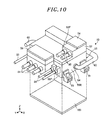
- Fig. 10 is an exploded perspective view showing a power converter 10 according to a modified example.
- the first accommodation part 40 is separable from the second accommodation part 50.
- a DC-DC converter is mounted to the motor vehicle 1 in advance and the first accommodation part 40 including the DC-DC converter circuit unit 31 is not needed in the power converter 10.
- the first accommodation part 40 is removed from the second accommodation part 50.
- the power converter 10 includes only the second accommodation part 50 provided with the inverter circuit unit 21.
- Fig. 10 shows the power converter 10 in which the first accommodation part 40 is removed from the second accommodation part 50.
- the power converter 10 according to the modified example can easily cope with the specifications of the motor vehicle 1 (e.g., the specifications in which a DC-DC converter is mounted in advance) by removing the first accommodation part 40 including the DC-DC converter circuit unit 31 from the second accommodation part 50.
- the specifications of the motor vehicle 1 e.g., the specifications in which a DC-DC converter is mounted in advance
- the power converter 10 can easily cope with the requirement by merely combining the first accommodation part 40 including the DC-DC converter circuit unit 31 with the second accommodation part 50.
- a third cover 100 is attached to the third opening portion 513 (not visible in Fig. 10 ). Unlike the shape of the first cover 42, the third cover 100 is identical in shape with the upper surface 40A of the removed first accommodation part 40. More precisely, the size of the third cover 100 and the attachment positions of fixing members (e.g., bolts) in the third cover 100 are set to become identical or substantially identical with those of the upper surface 40A of the first accommodation part 40.
- the third opening portion 513 can be closed by the third cover 100 even when the first accommodation part 40 is removed. It is therefore possible to prevent dust or water from entering the internal space of the second accommodation part 50 through the third opening portion 513.
- the third cover 100 is identical in shape with the upper surface 40A of the first accommodation part 40 as set forth above, fixing members for attaching the third cover 100 to the second accommodation part 50 and fixing members for fixing the first accommodation part 40 to the second accommodation part 50 can be used in common.
Landscapes
- Engineering & Computer Science (AREA)
- Microelectronics & Electronic Packaging (AREA)
- Physics & Mathematics (AREA)
- Thermal Sciences (AREA)
- Power Engineering (AREA)
- Transportation (AREA)
- Mechanical Engineering (AREA)
- Electric Propulsion And Braking For Vehicles (AREA)
- Inverter Devices (AREA)
- Dc-Dc Converters (AREA)
Applications Claiming Priority (1)
| Application Number | Priority Date | Filing Date | Title |
|---|---|---|---|
| JP2014039458A JP2015164367A (ja) | 2014-02-28 | 2014-02-28 | 電力変換装置および車両 |
Publications (2)
| Publication Number | Publication Date |
|---|---|
| EP2914076A2 true EP2914076A2 (fr) | 2015-09-02 |
| EP2914076A3 EP2914076A3 (fr) | 2015-12-16 |
Family
ID=52577776
Family Applications (1)
| Application Number | Title | Priority Date | Filing Date |
|---|---|---|---|
| EP15156891.2A Withdrawn EP2914076A3 (fr) | 2014-02-28 | 2015-02-27 | Convertisseur de puissance et véhicule à moteur |
Country Status (6)
| Country | Link |
|---|---|
| US (1) | US20150246619A1 (fr) |
| EP (1) | EP2914076A3 (fr) |
| JP (1) | JP2015164367A (fr) |
| KR (1) | KR20150102722A (fr) |
| CN (2) | CN204517646U (fr) |
| EA (1) | EA201500180A3 (fr) |
Families Citing this family (12)
| Publication number | Priority date | Publication date | Assignee | Title |
|---|---|---|---|---|
| JP2015164367A (ja) * | 2014-02-28 | 2015-09-10 | 株式会社安川電機 | 電力変換装置および車両 |
| KR101905997B1 (ko) * | 2016-11-09 | 2018-10-08 | 현대자동차주식회사 | 차량탑재형 충전장치 |
| CN106696858A (zh) * | 2016-12-23 | 2017-05-24 | 中国第汽车股份有限公司 | 一种电动汽车高压功率电子装置布置结构 |
| DE112018000388T5 (de) * | 2017-03-30 | 2019-09-26 | Hitachi Automotive Systems, Ltd. | Leistungswandler |
| JP6785274B2 (ja) | 2018-10-02 | 2020-11-18 | 本田技研工業株式会社 | 電気機器 |
| JPWO2021149214A1 (fr) * | 2020-01-23 | 2021-07-29 | ||
| JP6806276B1 (ja) * | 2020-03-05 | 2021-01-06 | 富士電機株式会社 | 電力変換装置 |
| KR102320181B1 (ko) * | 2020-05-29 | 2021-11-03 | 영화테크(주) | 수소연료 자동차용 전력변환장치 |
| CN112706631B (zh) * | 2020-12-21 | 2022-04-26 | 中车永济电机有限公司 | 一种高功率密度水冷双向充电机装置 |
| CN115489297A (zh) * | 2021-06-18 | 2022-12-20 | 比亚迪股份有限公司 | 车辆控制器和具有其的车辆 |
| US12122251B2 (en) * | 2022-09-28 | 2024-10-22 | BorgWarner US Technologies LLC | Systems and methods for bidirectional message architecture for inverter for electric vehicle |
| WO2024152300A1 (fr) * | 2023-01-19 | 2024-07-25 | 宁德时代(上海)智能科技有限公司 | Ensemble d'échange de chaleur, corps de boîtier, dispositif de commande, dispositif d'entraînement et appareil électrique |
Citations (1)
| Publication number | Priority date | Publication date | Assignee | Title |
|---|---|---|---|---|
| JPH0331669B2 (fr) | 1986-06-11 | 1991-05-08 | Hajime Saito |
Family Cites Families (16)
| Publication number | Priority date | Publication date | Assignee | Title |
|---|---|---|---|---|
| JP3031669B2 (ja) * | 1997-10-13 | 2000-04-10 | 株式会社デンソー | 電力用回路モジュール |
| JP2001045601A (ja) * | 1999-07-27 | 2001-02-16 | Hitachi Ltd | 自動車駆動装置 |
| JP3676719B2 (ja) * | 2001-10-09 | 2005-07-27 | 株式会社日立製作所 | 水冷インバータ |
| JP2006230064A (ja) * | 2005-02-16 | 2006-08-31 | Toyota Motor Corp | 電力変換ユニット |
| JP4538359B2 (ja) * | 2005-03-31 | 2010-09-08 | 株式会社日立産機システム | 電気回路モジュール |
| JP4962184B2 (ja) * | 2007-07-18 | 2012-06-27 | トヨタ自動車株式会社 | 車両の電源装置 |
| JP2009027901A (ja) * | 2007-07-24 | 2009-02-05 | Toyota Motor Corp | 電力変換装置 |
| JP5131556B2 (ja) * | 2008-11-14 | 2013-01-30 | 株式会社デンソー | 電力変換装置 |
| JP4951646B2 (ja) * | 2009-03-26 | 2012-06-13 | 本田技研工業株式会社 | 端子台およびインバータケース |
| JP5099086B2 (ja) * | 2009-07-28 | 2012-12-12 | 株式会社デンソー | 電源装置 |
| KR101039678B1 (ko) * | 2009-11-17 | 2011-06-09 | 현대자동차주식회사 | 하이브리드 차량의 전력변환장치 냉각 제어 방법 |
| JP5423998B2 (ja) * | 2011-08-31 | 2014-02-19 | 株式会社安川電機 | 電子部品冷却ユニット及び電力変換装置 |
| JP5708390B2 (ja) * | 2011-09-07 | 2015-04-30 | 株式会社デンソー | 電子回路装置 |
| JP5855899B2 (ja) * | 2011-10-27 | 2016-02-09 | 日立オートモティブシステムズ株式会社 | Dc−dcコンバータ及び電力変換装置 |
| WO2013080665A1 (fr) * | 2011-11-30 | 2013-06-06 | 本田技研工業株式会社 | Unité de commande d'alimentation |
| JP2015164367A (ja) * | 2014-02-28 | 2015-09-10 | 株式会社安川電機 | 電力変換装置および車両 |
-
2014
- 2014-02-28 JP JP2014039458A patent/JP2015164367A/ja active Pending
-
2015
- 2015-02-26 KR KR1020150027586A patent/KR20150102722A/ko not_active Ceased
- 2015-02-26 EA EA201500180A patent/EA201500180A3/ru unknown
- 2015-02-27 EP EP15156891.2A patent/EP2914076A3/fr not_active Withdrawn
- 2015-02-27 US US14/633,899 patent/US20150246619A1/en not_active Abandoned
- 2015-02-28 CN CN201520119091.0U patent/CN204517646U/zh not_active Expired - Lifetime
- 2015-02-28 CN CN201510092989.8A patent/CN104883040A/zh active Pending
Patent Citations (1)
| Publication number | Priority date | Publication date | Assignee | Title |
|---|---|---|---|---|
| JPH0331669B2 (fr) | 1986-06-11 | 1991-05-08 | Hajime Saito |
Also Published As
| Publication number | Publication date |
|---|---|
| EP2914076A3 (fr) | 2015-12-16 |
| EA201500180A3 (ru) | 2015-11-30 |
| KR20150102722A (ko) | 2015-09-07 |
| CN204517646U (zh) | 2015-07-29 |
| JP2015164367A (ja) | 2015-09-10 |
| EA201500180A2 (ru) | 2015-08-31 |
| US20150246619A1 (en) | 2015-09-03 |
| CN104883040A (zh) | 2015-09-02 |
Similar Documents
| Publication | Publication Date | Title |
|---|---|---|
| EP2914076A2 (fr) | Convertisseur de puissance et véhicule à moteur | |
| US10512198B2 (en) | Power converter | |
| JP5099431B2 (ja) | インバータユニット | |
| US10381922B2 (en) | Power converter | |
| US9048721B2 (en) | Semiconductor device | |
| US20130301328A1 (en) | Power conversion apparatus | |
| CN107710587B (zh) | 电力转换装置 | |
| JP6252457B2 (ja) | 車載電子機器 | |
| KR20160129696A (ko) | 전자 기기의 냉각용 케이스, 전자 기기 및 건설 기계 | |
| US12143025B2 (en) | Inverter device, motor unit, and vehicle | |
| CN217428001U (zh) | 逆变器装置、马达单元及车辆 | |
| JP2017200314A (ja) | 電力変換装置 | |
| US20230188007A1 (en) | Rotary electric machine unit | |
| US11854729B2 (en) | Direct liquid cooled inductor | |
| CN113572314A (zh) | 多功能控制器和动力总成 | |
| CN111756253A (zh) | 逆变器装置 | |
| JP5919419B1 (ja) | 電力変換装置 | |
| KR102426767B1 (ko) | 전력제어장치 | |
| JP2016152637A (ja) | 電力変換器 | |
| US12374955B2 (en) | Rotary electric machine unit | |
| JP2016220341A (ja) | 電力変換装置 | |
| JP7264159B2 (ja) | 電力変換装置 | |
| CN114337319B (zh) | 液体循环结构、逆变器装置和车辆 | |
| JP7536725B2 (ja) | Pcuケース | |
| JP5919420B1 (ja) | 電力変換装置 |
Legal Events
| Date | Code | Title | Description |
|---|---|---|---|
| PUAI | Public reference made under article 153(3) epc to a published international application that has entered the european phase |
Free format text: ORIGINAL CODE: 0009012 |
|
| AK | Designated contracting states |
Kind code of ref document: A2 Designated state(s): AL AT BE BG CH CY CZ DE DK EE ES FI FR GB GR HR HU IE IS IT LI LT LU LV MC MK MT NL NO PL PT RO RS SE SI SK SM TR |
|
| AX | Request for extension of the european patent |
Extension state: BA ME |
|
| PUAL | Search report despatched |
Free format text: ORIGINAL CODE: 0009013 |
|
| AK | Designated contracting states |
Kind code of ref document: A3 Designated state(s): AL AT BE BG CH CY CZ DE DK EE ES FI FR GB GR HR HU IE IS IT LI LT LU LV MC MK MT NL NO PL PT RO RS SE SI SK SM TR |
|
| AX | Request for extension of the european patent |
Extension state: BA ME |
|
| RIC1 | Information provided on ipc code assigned before grant |
Ipc: H05K 7/20 20060101AFI20151109BHEP |
|
| STAA | Information on the status of an ep patent application or granted ep patent |
Free format text: STATUS: THE APPLICATION IS DEEMED TO BE WITHDRAWN |
|
| 18D | Application deemed to be withdrawn |
Effective date: 20160617 |