EP2914191B1 - Apparatus and probe for a cryogenic system - Google Patents
Apparatus and probe for a cryogenic system Download PDFInfo
- Publication number
- EP2914191B1 EP2914191B1 EP12797957.3A EP12797957A EP2914191B1 EP 2914191 B1 EP2914191 B1 EP 2914191B1 EP 12797957 A EP12797957 A EP 12797957A EP 2914191 B1 EP2914191 B1 EP 2914191B1
- Authority
- EP
- European Patent Office
- Prior art keywords
- cryogen
- probe
- vacuum
- line
- source
- Prior art date
- Legal status (The legal status is an assumption and is not a legal conclusion. Google has not performed a legal analysis and makes no representation as to the accuracy of the status listed.)
- Active
Links
Images


Classifications
-
- A—HUMAN NECESSITIES
- A61—MEDICAL OR VETERINARY SCIENCE; HYGIENE
- A61B—DIAGNOSIS; SURGERY; IDENTIFICATION
- A61B18/00—Surgical instruments, devices or methods for transferring non-mechanical forms of energy to or from the body
- A61B18/02—Surgical instruments, devices or methods for transferring non-mechanical forms of energy to or from the body by cooling, e.g. cryogenic techniques
- A61B18/0218—Surgical instruments, devices or methods for transferring non-mechanical forms of energy to or from the body by cooling, e.g. cryogenic techniques with open-end cryogenic probe, e.g. for spraying fluid directly on tissue or via a tissue-contacting porous tip
-
- A—HUMAN NECESSITIES
- A61—MEDICAL OR VETERINARY SCIENCE; HYGIENE
- A61B—DIAGNOSIS; SURGERY; IDENTIFICATION
- A61B18/00—Surgical instruments, devices or methods for transferring non-mechanical forms of energy to or from the body
- A61B18/02—Surgical instruments, devices or methods for transferring non-mechanical forms of energy to or from the body by cooling, e.g. cryogenic techniques
-
- A—HUMAN NECESSITIES
- A61—MEDICAL OR VETERINARY SCIENCE; HYGIENE
- A61B—DIAGNOSIS; SURGERY; IDENTIFICATION
- A61B18/00—Surgical instruments, devices or methods for transferring non-mechanical forms of energy to or from the body
- A61B2018/00005—Cooling or heating of the probe or tissue immediately surrounding the probe
- A61B2018/00041—Heating, e.g. defrosting
-
- A—HUMAN NECESSITIES
- A61—MEDICAL OR VETERINARY SCIENCE; HYGIENE
- A61B—DIAGNOSIS; SURGERY; IDENTIFICATION
- A61B18/00—Surgical instruments, devices or methods for transferring non-mechanical forms of energy to or from the body
- A61B2018/00053—Mechanical features of the instrument of device
- A61B2018/00059—Material properties
- A61B2018/00089—Thermal conductivity
- A61B2018/00101—Thermal conductivity low, i.e. thermally insulating
-
- A—HUMAN NECESSITIES
- A61—MEDICAL OR VETERINARY SCIENCE; HYGIENE
- A61B—DIAGNOSIS; SURGERY; IDENTIFICATION
- A61B18/00—Surgical instruments, devices or methods for transferring non-mechanical forms of energy to or from the body
- A61B18/02—Surgical instruments, devices or methods for transferring non-mechanical forms of energy to or from the body by cooling, e.g. cryogenic techniques
- A61B2018/0212—Surgical instruments, devices or methods for transferring non-mechanical forms of energy to or from the body by cooling, e.g. cryogenic techniques using an instrument inserted into a body lumen, e.g. catheter
-
- A—HUMAN NECESSITIES
- A61—MEDICAL OR VETERINARY SCIENCE; HYGIENE
- A61B—DIAGNOSIS; SURGERY; IDENTIFICATION
- A61B18/00—Surgical instruments, devices or methods for transferring non-mechanical forms of energy to or from the body
- A61B18/02—Surgical instruments, devices or methods for transferring non-mechanical forms of energy to or from the body by cooling, e.g. cryogenic techniques
- A61B2018/0231—Characteristics of handpieces or probes
- A61B2018/0262—Characteristics of handpieces or probes using a circulating cryogenic fluid
- A61B2018/0268—Characteristics of handpieces or probes using a circulating cryogenic fluid with restriction of flow
- A61B2018/0275—Characteristics of handpieces or probes using a circulating cryogenic fluid with restriction of flow using porous elements
-
- A—HUMAN NECESSITIES
- A61—MEDICAL OR VETERINARY SCIENCE; HYGIENE
- A61B—DIAGNOSIS; SURGERY; IDENTIFICATION
- A61B18/00—Surgical instruments, devices or methods for transferring non-mechanical forms of energy to or from the body
- A61B18/02—Surgical instruments, devices or methods for transferring non-mechanical forms of energy to or from the body by cooling, e.g. cryogenic techniques
- A61B2018/0231—Characteristics of handpieces or probes
- A61B2018/0262—Characteristics of handpieces or probes using a circulating cryogenic fluid
- A61B2018/0268—Characteristics of handpieces or probes using a circulating cryogenic fluid with restriction of flow
- A61B2018/0281—Characteristics of handpieces or probes using a circulating cryogenic fluid with restriction of flow using a tortuous path, e.g. formed by fins or ribs
-
- A—HUMAN NECESSITIES
- A61—MEDICAL OR VETERINARY SCIENCE; HYGIENE
- A61B—DIAGNOSIS; SURGERY; IDENTIFICATION
- A61B18/00—Surgical instruments, devices or methods for transferring non-mechanical forms of energy to or from the body
- A61B18/02—Surgical instruments, devices or methods for transferring non-mechanical forms of energy to or from the body by cooling, e.g. cryogenic techniques
- A61B2018/0293—Surgical instruments, devices or methods for transferring non-mechanical forms of energy to or from the body by cooling, e.g. cryogenic techniques using an instrument interstitially inserted into the body, e.g. needle
Definitions
- the present invention relates to an apparatus for cryosurgery.
- Cryosurgery is the controlled destruction of unwanted tissue by the application of extreme cold.
- the extreme cold causes water in cells to freeze and this freezing kills the cells.
- Cells are known to be killed after exposure to temperatures below -20 °C. It is known to use cryogenic systems in cryo-ablation and cryo-analgesia surgeries.
- Cryosurgery is a well-established clinical technique for treating common soft tissue tumours in cancer cases involving the liver, kidney, prostate, breast and lung. Cryosurgery enables tumours, which are regarded as inoperable by other means, to be treated with excellent postoperative morbidity. More recently, the technique has expanded into other fields including podiatry for treating conditions such as Morton's Neuroma and Plantar fasciitis. Cryosurgery Neuroablation is an effective, safe, minimally invasive clinically proven procedure that can be performed in the office setting. Apparatus and methods for performing cryogenic ablation of tissue are described in US 2009/287202 .
- Cryogenic systems for surgical applications generally use one of two distinct mechanisms to achieve the required cooling.
- the favoured cryo-surgery mechanism uses a Joule-Thompson device, for example as described in GB2337000 .
- These devices rely on the Joule-Thompson effect to induce cooling by expansion of a high pressure gas (e.g. N 2 O) through a small orifice.
- a high pressure gas e.g. N 2 O
- Such devices require the deployment of high pressure gas in vivo.
- the high pressure gas is delivered to an expansion orifice within the probe, where the gas expands to produce the required cooling via the Joule-Thompson effect. If the gas escapes into the patient serious damage may be done.
- gaseous matter within the body can be seriously damaging. A jet of compressed gas at 1500 psi escaping from even a very small hole would cause significant damage to soft tissue structures. Additionally if such gaseous matter makes its way to the heart via the cardiovascular system as cardiac arrest may result.
- Liquid cryogenic devices rely on evaporation of a liquid, such as liquid nitrogen or helium, to produce cooling by boiling and/or evaporation.
- a liquid such as liquid nitrogen or helium
- the capacity of liquid cryogenic systems to absorb heat is vastly superior to the capacity of Joule-Thompson devices to absorb heat. This is because the latent heat of vaporisation for most cryogenic fluids commonly used in liquid cryogenic systems is significantly greater than the heat absorbed by the expanding gas(es) commonly used within Joule-Thompson systems.
- liquid cryogen cryosurgery apparatus or apparatus for cryosurgery comprising a source of liquid cryogen, a delivery line for delivering liquid cryogen to a probe, an exhaust line for receiving cryogen from a probe, a vacuum source in fluid communication with the exhaust line operable to draw cryogen, in use, from the source of liquid cryogen to the probe and into the exhaust line.
- This liquid cryogenic system enables more efficient cooling of the probe than that provided by the prior art, by overcoming, or at least substantially reducing, phasing and its associated drawbacks.
- the cryogen source may comprise a source of gaseous cryogen.
- the vacuum source may be configured to continuously evacuate the exhaust line.
- the vacuum source may be downstream of the exhaust line.
- a vacuum reservoir may be provided upstream of the vacuum source.
- the vacuum reservoir may be in communication with a heat exchanger, heating element or other cryogen heating means.
- a heat exchanger heating means or other cryogen heating means is provided within the vacuum reservoir, which is preferably upstream of the vacuum source.
- a cryogen exhaust conduit e.g. for the exhaust of cryogen, is provided in the line, preferably concentrically between the supply conduit and insulating conduit.
- Thermally insulating spacers may be present in parts of the line outside the supply conduit, e.g. in the insulating conduit and/or in the exhaust conduit. Spacers may be fabricated from glass, ceramics, plastics or other materials resistant to damage from thermal cycling and or the conditions found under autoclave or other cleaning/sterilising regimes.
- the apparatus may comprise a flexible line for the supply of cryogen in a cryosurgery apparatus, the line comprising an array of articulated members of low thermal conductivity, each having a passage there through for the flow of cryogen.
- the probe may also comprise a concentric peripheral insulating conduit, being provided around the exhaust line and being continuously evacuable.
- the apparatus may be configured such that the cryogen received from the probe is re-circulated for re-delivery to the probe.
- the exhaust line may comprise peripheral insulation.
- the peripheral insulation may be provided, at least in part, by a vacuum jacket, wherein the vacuum jacket may be in fluid communication with the vacuum source.
- the vacuum jacket may be in fluid communication with the exhaust line.
- the vacuum jacket may comprise a one way valve.
- the apparatus may further comprise a delivery line configured to deliver cryogen to the probe, wherein the dispersive medium may be configured so as to enable fluid communication between the delivery line and the vacuum source.
- the apparatus may further comprise a delivery line configured to deliver liquid cryogen to the probe, wherein for at least part of its length the delivery line extends along at least part of the exhaust line.
- the apparatus may comprise a primary cryogen source and a secondary cryogen source.
- the secondary source is filled with cryogen from the primary source prior to commencing cryosurgery.
- a conduit between the primary and secondary sources is permanently insulated, e.g. it comprises a conduit with a permanent vacuum jacket and/or other insulation.
- the conduit between the primary and secondary sources may be less than 2m, say less than 1.75, or 1.5, 1.4, 1.3, 1.2, 1.1 or 1.0m in length.
- a conduit between the secondary source and the probe may be less than 2m, say less than 1.75, or 1.5, 1.4, 1.3, 1.2, 1.1 or 1.0m in length.
- the secondary source may comprise a thermocouple or other content measuring device.
- the content measuring device may be operable to automatically control the flow of cryogen from the primary to secondary source.
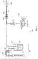
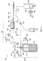
- a cryogenic system indicated generally at 101, comprises apparatus for supplying liquid cryogen 103, a probe 105, and a vacuum source 107.
- the apparatus for supplying liquid cryogen 103 is connected to the probe 105 by means of delivery line 109.
- the probe 105 is also connected to the vacuum source 107 by means of exhaust line 111.
- the vacuum source 107 i.e. source of negative pressure compared to that of atmospheric pressure, is configured such that it can suck or draw the liquid cryogen to the probe 105.
- a pressure source i.e. a source of positive pressure compared to that of atmospheric pressure, to force the liquid cryogen to the probe.
- the apparatus for supplying liquid cryogen 103 may comprise a source of liquid cryogen which is drawn to the probe 105 via the vacuum source 107.
- the apparatus for supplying liquid cryogen 103 may comprise a means for supplying propellant gas 113, a Dewar 115, and a pipe 117 which, in use, has an end beneath the surface of the liquid cryogen.
- the means for supplying a propellant gas 113 comprises a nitrogen gas cylinder 119, which is connected to a manifold 121.
- the manifold 121 is connected to a valve 123, the valve 123 is operable to regulate the pressure of the propellant gas.
- the valve 123 is connected to the Dewar 115.
- propellant gas is fed above the surface of the liquid cryogen contained within Dewar 115.
- the Dewar 115 is configured such that, in use, the pressure of the propellant gas may displace liquid cryogen along the pipe 117.
- the pipe 117 has, in use, one end beneath the surface of the liquid cryogen contained within the Dewar 115 and the other end is connected to delivery line 109.
- the provision of such a means for applying pressure to the liquid cryogen to force it through the delivery line 109 to the probe 105 is not essential. Instead, other examples rely on the provision of a downstream vacuum or reduced pressure source to draw up/suck the liquid cryogen to the probe 105.
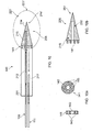
- a probe 105 for use with an example of the present invention is shown in more detail in Figure 2 .
- the probe 105 comprises a proximal end 201 and a distal end 203. At the proximal end 201 of probe 105 is a fitting 207 for connection to the delivery line 109 and the exhaust line 111.
- the fitting 207 comprises an inlet 209 and an outlet 211. In use, the inlet 209 is connected to delivery line 109 and the outlet 211 is connected to the exhaust line 111.
- the inlet 209 is also connected to, that is in fluid communication with, tip 205 at the distal end 203 of the probe 105 by means of a delivery tube 212.
- liquid cryogen may flow from the delivery line 109 to the probe tip 205 at the distal end 203 of the probe 105 via inlet 209 and delivery tube 212.
- the probe tip 205 is thermally conducting. It may also be impermeable or semipermeable to liquid cryogen. Thus, the probe tip 205 is operable as a heat exchanger.
- the outer surface 214 of tip 205 is of a thermally conducting substance, for example gold (chosen for its conductivity and sterilisability).
- Within tip 205 is a region 215 of a dispersive medium through which the cryogen is delivered/passed through for dispersal.
- the dispersive medium 215 provides a plurality of nucleation sites for the liquid cryogen, to encourage nucleation, boiling and/or evaporation of the liquid cryogen passing therethrough to effect optimal thermal transfer and heat exchange.
- the dispersive medium is thermally coupled/in thermal communication with the outer surface 214 of the probe tip 205. In use, the dispersive medium and the outer surface 214 of the probe tip, are cooled due to liquid cryogen's boiling and/or evaporation when in contact with the dispersive medium 215.
- the dispersive medium may be formed of a thermally conductive and porous material.
- the dispersive medium may be formed of a sintered material.
- the sintered material may be a sintered: metal (such as at least one of: Aluminium, Copper and Bronze or other metals), ceramic, plastic or any other material suitable for sintering.
- the probe 105 also comprises an exhaust tube 217, which connects the probe tip 205 to the outlet 211.
- the inlet 209 and outlet 211 are in fluid communication via the dispersive medium region 215 within the tip 205 at the distal end 203 of the probe 105.
- a high volume of gas may be generated in the probe tip following boiling/evaporation of the liquid cryogen.
- liquid nitrogen has an expansion ration of approximately 700 to 1.
- a porous, dispersive and diffusive medium enables the cryogen, having transformed from a liquid to a gaseous state, to pass through the dispersive medium and out through the outlet 211 and exhaust line 111.
- Probe 105 also comprises insulated region 219.
- the insulation may be provided by one or more of a vacuum, partial vacuum, or other means such as a material with low thermal conductivity. In use, this region may be in contact with tissue which is not to be damaged by the extreme cold of the cryosurgery.
- the insulated region 219 may be fabricated to allow cleaning of the probe 105, e.g. by autoclaving. For example the insulated region 219 may be removable or made from cleaning-resistant materials, a cleanable probe is likely to be re-usable.
- the probe insulating region 219 may be evacuated by the vacuum source 107.
- the probe 105 is also connected to the vacuum source 107.
- the exhaust line 111 is connected to the outlet 211 of the probe 105.
- the exhaust line 111 is connected to a vacuum reservoir 125 and a pump 127 via valve 129.
- the pump 127 is operable to produce a vacuum within reservoir 125.
- the vacuum pump 127 vents to the atmosphere, generally via a scavenging connection to meet safety requirements.
- the valve 129 is operable to control the vacuum supplied by the pump 127 and reservoir 125 to the exhaust line 111.
- the exhaust line 111 supplies means for supplying propellant gas 113 a vacuum to the probe 105 and the probe 105 in turn supplies vacuum to the delivery line 109.
- the liquid cryogen can be urged/drawn/sucked through the delivery line 109 to the probe tip via a lifting effect on the source of the liquid cryogen due to a vacuum "down-stream" of the probe tip, e.g. in the exhaust side of the system, rather than using a source of positive pressure "up-stream” of the probe tip, e.g. in the delivery side of the system.
- a porous permeable dispersive medium such as a sintered material, enables the lifting effect of the "down-stream” vacuum/suction to pass therethrough, thereby communicating the vacuum/suction to the liquid cryogen source via the delivery line.
- the invention enables the use of negative pressure compared to that of atmospheric pressure to draw up the liquid cryogen to the probe tip rather than positive pressure to force the liquid cryogen to the probe tip.
- the invention enables the liquid cryogen to be delivered to the probe tip by being "sucked" along to the probe tip by a vacuum or source of reduced (sub-atmospheric) pressure down-stream of the probe tip rather than relying on active pressure applied up-stream of the probe tip (as occurs in previous cryogenic systems).
- the apparatus for supplying liquid cryogen 103 and the vacuum source 107 may be located within a common housing.
- Previous cryogenic systems required a pump on a delivery side to create a positive pressure to force liquid coolant to the probe tip.
- Examples of the present invention enable a pump at an exhaust side to be used instead to create vacuum (negative pressure) to cause the liquid coolant to be drawn to the probe tip.
- An alternative probe 300 is shown in Figure 3 .
- the alternative probe 300 is similar to that described and shown in Figure 2 , only the differences will be described.
- the alternative probe 300 comprises at the proximal end 201 an additional port 301 within the fitting 207.
- the fitting 301 is connected to vacuum insulated region 219. In this way, it is not necessary to provide a probe 105 which is capable of holding a vacuum within region 219 for the entire lifetime of the probe 300. Vacuum insulation for region 219 may be supplied by vacuum source 107 via port 301. Because there are no sealed portions the probe 300 is capable of cleaning, e.g. by autoclaving and is thus capable of re-use.
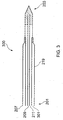
- FIG. 4 Shown in Figure 4 is a tri-axial line 401 for use with an example of the cryogenic system 101.
- the tri-axial line 401 may be present from the connector 131 to the probe 105 only or used elsewhere within the cryogenic system 101.
- the tri-axial line comprises a feed line 403, an exhaust line 405 and an insulating line 407.
- the feed line 403 is within the exhaust line 405 which, in turn, is within the insulating line 407.
- the exhaust line 405 and the insulating line 407 act together to reduce undesirable condensation on the outside 409 of the tri-axial line 401 and reduce evaporation losses from the supply of cryogen via the feed line 403.
- a vacuum preferably from the vacuum source 107 is applied to the insulating line 407.
- the vacuum may be provided via a split or controllable flow so that a greater vacuum is applied to one or other of the exhaust 405 and insulating 407 lines.
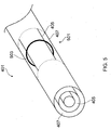
- FIG. 5 which is an alternative view of the tri-axial line 401, having a cutaway section 501 for illustrative purposes only, shows that the tri-axial line 401 comprises a spacer 503.
- the spacer 503 is within insulating line 407.
- the spacer 503 is made of an insulating material, for example glass or ceramics.
- the spacer 503 acts to prevent the exhaust line 405 from touching the insulating line 407. In this way the effectiveness of the insulating line 407 is increased. Performance is markedly increased when the tri-axial line 401 is bent, as in this formation the spacer 503 prevents the exhaust line 405 from touching the insulating line 407.
- the spacers 503 are positioned along the length of the tri-axial line. They may be any shape but they must allow the passage of fluids so as not to inhibit exhaust flow and so on.
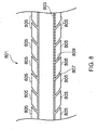
- FIG. 6 shows an alternative tri-axial line 601 in cross sectional schematic view.
- the alternative tri-axial line 601 also comprises a central delivery line 603, an exhaust line 605 and a peripheral insulating line 607.
- the insulating line 607 does not have a separate connector at the end of the line 601. Instead, vacuum is provided within insulating line 607 by the vacuum supplied to exhaust line 605. This vacuum is supplied by means of valve 609, valve 609 permits flow of fluids from insulating line 607 to exhaust line 605 only.
- any vacuum applied to exhaust line 605 will become present in insulating line 607, however, if insulating line 607 comprises a vacuum and an exhaust line 605 is pressurised relative to insulating line 607 then the vacuum in insulating line 607 will remain substantially intact.
- the alternative tri-axial line 601 also features insulating spacers 503.
- the tri-axial lines 401, 601 are advantageous as the boil off, which is at a temperature between the temperature of the cryogenic liquid and the ambient temperature, provides a layer of insulation between the delivery line 403, 603 and the insulating line 407.
- This insulation is provided by cold gases, that in prior art systems would have merely been vented to the atmosphere.
- the cold gas flowing from the probe will help to cool the delivery line 603 as cryogen is supplied.
- the vacuum in the insulating line 607 will help to ensure the insulation.
- these tri-axial lines 401, 601 are advantageous, as in order to allow for re-use of a line in surgery it must be sterilisable. Sterilisation is generally accomplished by autoclaving, which consists essentially of high pressure and temperature steam treatment.
- the present tri-axial lines 401, 601 mitigate the need to provide an insulating line capable of maintaining a vacuum after several autoclave cycles.
- FIG. 7A shows an alternative line 701 in schematic cross-sectional view for use with examples of the present invention.
- the alternative line 701 is a bi-axial line, and comprises a central delivery line 703 and an exhaust line 705.
- the delivery line 703 is within the exhaust line 705.
- the exhaust line 705, in use, carries cold boil off away from the probe. Hence, in use, the cold boil off acts to insulate delivery line 703 from ambient temperatures. This reduces undesirable condensation on the outside of the bi-axial line 701 and evaporation losses from the supply of cryogen via the delivery line 703.
- the exhaust line 705 may be of a flexible material, such as silglass, accordingly, spiders 707 or other suitable spacers may be provided to prevent the exhaust line 705 completely collapsing under vacuum, when used with the present invention.
- Figure 7B shows an alternative example of line 701' the supply line 703' can be surrounded by an insulating line 708.
- a separate exhaust line 705' is provided to take nitrogen gas from the probe tip.
- the insulating line has a vacuum applied thereto.
- the vacuum is provided by the vacuum source in communication with the exhaust line 705'.
- FIG 8 shows an alternative delivery line assembly 801 in schematic cross-sectional view for use with the present invention.
- the delivery line assembly 801 comprises a delivery line 803, which is insulated by means of ceramic collars 805.
- the ceramic collars 805 lie adjacent each other and cover substantially the whole length of the feed line 803.
- the ceramic collars 805 have a concave curved portion 807 at one end and a convex curved portion 809 at the other end.
- the concave curved portion 807 of one ceramic collar is complementary with a convex curved portion 809 of another, such that the delivery line 803 may be bent and still substantially insulated by the ceramic collars 805.
- the ceramic collars 805 may be glazed, such that they are impermeable. Such glazed ceramic collars are more hygienic than unglazed ceramic collars.
- the delivery line assembly 801 is durable and can be sterilised by means of an autoclave, accordingly, such delivery line assemblies 801 are advantageous.
- any of the tri-axial line 401, the alternative tri-axial line 601, the alternative bi-axial line 701 or the delivery line assembly 801 may be used with any of the described cryogenic systems.
- FIG. 9 shows a further cryogenic system, indicated generally at 901.
- the cryogenic system 901 comprises apparatus for supplying liquid cryogen 903, an intermediate cryogen storage apparatus 905, a probe 907, and a vacuum source 909.
- the apparatus for supplying liquid cryogen 903 is connected to the probe via supply line 911, intermediate cryogen storage apparatus 905, and delivery line 913.
- the probe 907 is also connected to the vacuum source 909 by means of exhaust line 915.
- the apparatus for supplying liquid cryogen 903 (which may be that as described in WO 96/30816 the entire disclosure of which is included herein by reference) comprises a means for supplying propellant gas, a Dewar 917, and a supply pipe 919 which, in use, has an end beneath the surface of the liquid cryogen.
- the Dewar 917 may be of any appropriate size and may be approximately 60 litres.
- the means for supplying a propellant gas comprises a pressure raising coil 921, an automatic pressure control valve 923, and a pressure control regulator 925.
- the pressure raising coil 921 is connected to the automatic pressure control valve 923 which is operable to regulate the pressure of the propellant gas by the user.
- the pressure control valve 925 is connected to the pressure control regulator 925.
- the pressure control regulator 925 is operable to maintain a preset propellant gas pressure within the Dewar 917 when the pressure control valve 923 is open.
- the preset propellant gas pressure may be of any appropriate value, e.g. 414 kPa (60 psi).
- the pressure control regulator 925 is connected to Dewar 917.
- propellant gas is fed above the surface of the liquid cryogen contained within the Dewar 917.
- the Dewar 917 is sealable such that, in use, the pressure of the propellant gas may displace liquid cryogen along the supply pipe 919.
- the supply pipe 919 has, in use, one end beneath the surface of the liquid cryogen contained within the Dewar 917 and the other end is connected to the supply line 911.
- the apparatus for supplying liquid cryogen 903, also comprises a fill line 927 and fill valve 929 for filling the Dewar 917 with liquid cryogen.
- the apparatus for supplying liquid cryogen 903 also comprises a contents gauge 931, the contents gauge 931 is a capacitance contents gauge which displays the remaining contents and communicates this value, for example to a control system.
- the apparatus 903 further comprises a safety relief valve 933 and a bursting disc 935 to prevent the apparatus 903 from reaching an excessive pressure.
- the apparatus 903 further comprises a pressure gauge 937 which displays the system pressure and communicates this value, for example to a control system.
- the apparatus 903 also comprises a gas vent 939 to release pressure within the apparatus 903 when desired.
- the cryogenic system 901 also comprises an optional intermediate cryogen storage apparatus 905 which connects the supply line 911 and the delivery line 913.
- the purpose of the intermediate cryogen storage apparatus 905 is to provide cryogen at a location nearer to the probe 907 than is possible in known prior art systems. Since the Dewar 917 of the apparatus for supplying liquid cryogen 903 has a volume of approximately 60 litres and a height of approximately 1 meter it is usually not possible for the apparatus for supplying liquid cryogen 903 to be in close proximity to the probe 907. The distance between the apparatus for supplying liquid cryogen 903 and the probe is typically 2 metres, the intermediate cryogen storage apparatus 905 is typically placed such that the supply line 911 and the delivery line 913 are 1 metre in length. However, the most important feature is to shorten the length of delivery line 913, such that the time from initiating cooling of the probe 907 to the probe 907 actually cooling is minimised.
- the intermediate cryogen storage apparatus 905 comprises an intermediate Dewar 941.
- the intermediate Dewar 941 connects the supply line 911 and the delivery line 913, its purpose is to allow the supply line 911 to be cooled to liquid cryogen temperature before the delivery line 913.
- the supply line 911 may be vacuum insulated. Such vacuum insulation, e.g. provided by a permanently vacuum insulated line, further reduces losses, e.g. evaporative losses, of cryogen.
- the intermediate cryogen storage apparatus 905 includes a vent valve 943, a thermocouple 945, a connection 947 to the supply line 911 and a connection 949 via the delivery line 913 to the probe 907.
- the connection to the delivery line 949 must be beneath the surface of the liquid cryogen in use, such that liquid cryogen is able to pass along the delivery line 913.
- the thermocouple 945 and the vent valve 943 must be towards the top of the intermediate Dewar 941, such that the thermocouple 945 can sense when the intermediate Dewar 941 is approaching full and the vent valve 943 can vent gaseous cryogen and not liquid cryogen.
- the intermediate cryogen storage apparatus 905 also comprises a safety relief valve 951 and a bursting disc 953 to prevent the apparatus 905 from reaching an excessive pressure.
- liquid nitrogen is fed from the apparatus for supplying liquid cryogen 903, by the propellant gas along the supply line 911 to intermediate Dewar 941. Whilst the cryogenic fluid is fed along (initially warm, that is above the boiling point of liquid nitrogen) the supply line 911 it boils and/or evaporates and the boil off is vented through vent valve 943. Once the intermediate Dewar 941 fills with liquid cryogen, the thermocouple 945 begins to cool. Once a predetermined temperature is reached (approximately the boiling point of the liquid cryogen in use) the propellant gas pressure is removed and the vent valve 943 is closed. In this way the supply line 911 can be cooled in advance of initiating a freeze state of the probe 907. Once the vent 943 is closed the whole assembly functions as a delivery line in order to allow cryogen flow to the probe 907 valve 961 is openable.
- the cryogenic system 901 also comprises means for warming the probe 907 as part of a thaw cycle.
- a heater 955 for heating nitrogen gas to thaw the probe.
- the heater 955 is connected to the delivery line 913 via a valve 957 and a three-way connection 959.
- a valve 961 between the intermediate cryogen storage apparatus 905 and the three-way connection 959. With this arrangement by operation of the valves 961, 957 it is possible to supply either liquid cryogen or hot nitrogen gas to the probe 907 as desired.
- By providing appropriate connections to the heater 955 it is possible to flow heated gas in either direction around the apparatus, as may be preferable.
- the probe 907 is connected to a vacuum source 909 by means of exhaust line 915.
- the vacuum source 909 comprises a vacuum tank 963, a pump 965 and a vent 967.
- the vacuum tank 963 also comprises a heater 969 within the base of the tank 963, the purpose of the heater 969 is to boil any liquid cryogen that may arrive in the vacuum reservoir 963.
- the delivery line 913 and the exhaust line 915 may be adjacent. Accordingly, the lines 913, 915 may be any of the tri-axial line 401, the alternative tri-axial line 601, the alternative line 701 or the delivery line assembly 801.
- the probe 105 (or any of 105, 300, 907) is inserted by a surgeon (the user) into a patient such that the region (such as a tumor) to be cryo-ablated is adjacent or in contact with the thermally conducting region of the tip 205.
- the cryogenic system 101 is activated when desired by the surgeon which may be before the probe is located in vivo.
- the valve 123 opens and propellant gas pressure is applied to Dewar 115.
- Dewar 115 is sealed such that the propellant gas acts on the liquid cryogen within Dewar 115.
- liquid cryogen is forced along the pipe 117 towards delivery line 109.
- the vacuum source 107 operates to provide a vacuum on exhaust line 111.
- the vacuum applied to exhaust line 111 is applied to the delivery line 109 and delivery tube 117 via the probe 105.
- the present invention may provide a probe which begins to cool after less than 2 minutes from initiation of a freezing cycle. Moreover, in the initial state the application of a vacuum ensures that air present in the conduits is swiftly drawn through the apparatus, thereby limiting the opportunity for liquefaction of the air or solidification of any water.
- liquid cryogen arrives at the probe 105.
- the liquid cryogen arrives at inlet 209 and is fed along feed tube 212 from the proximal end of the probe 201 to the distal end of the probe 203.
- the liquid cryogen arrives within the tip 205 of the probe 105.
- the liquid cryogen comes into contact with a dispersive medium such as a sintered bronze region 215 of the probe tip 205.
- the sintered bronze region 215 promotes boiling and/or evaporation by provision of nucleation sites.
- the boiling and/or evaporation of liquid cryogen in sintered bronze region 215 within the probe tip 205 cools the probe tip 205 to cryogenic temperatures.
- the probe tip 205 which is thermally conducting is thus able to cool surrounding tissue. This freezes the water in surrounding tissue and forms an ice ball 221. Cooling cells below -20°C is known to kill them.
- the sintered bronze region 215 is particularly advantageous as it promotes boiling and/or evaporation removing the latent heat of evaporation from the probe tip 205 and surrounding tissue, forming ice ball 221.
- the flow rate of liquid cryogen is controlled by the pressure of propellant gas acting on the liquid cryogen within Dewar 115 and the vacuum applied by vacuum source 107.
- the vacuum supplied by vacuum source 107 is controlled by valve 129, the pump 127 operating intermittently to provide a predetermined vacuum level within vacuum reservoir 125.
- significant quantities of liquid cryogen boil within sintered bronze region 215. That is - the flow rates are adjusted to favour boiling within region 215.
- the flow rate will be approximate between 5 and 6 litres per minute.
- cryogenic system 101 When the cryogenic system 101 is operating at its most efficient level all, or at least substantially all, of the liquid cryogen boils within the probe tip 205. Thus appropriate control of cryogen supply and vacuum application reduce wastage and ensure that the apparatus functions optimally.
- the size of the ice ball 221 grows. Once an ice ball 221 of a desired size is formed, the surgeon switches the system to thaw mode. In thaw mode, nitrogen gas is fed from nitrogen gas cylinder 119 to the heater which heats the nitrogen gas. The hot nitrogen gas is then fed along delivery line 109 to probe 105. The hot nitrogen gas displaces any liquid nitrogen remaining within the delivery line 109, probe 105 and exhaust line 111. Further, the hot nitrogen gas heats the probe tip 205. The sintered bronze region 215 having a large surface area readily absorbs heat from the nitrogen gas. Once the probe tip has thawed sufficiently it can be removed from the patient by the surgeon. The use of nitrogen as a purge gas (as opposed to, say, air) is preferably since it will only form nitrogen condensate (as opposed to water or other impure condensate).
- the system may also provide an auto clean function, which operates by venting high-pressure gas through the probe 105 in a reverse direction, along exhaust line 111 through probe 105 and exiting through delivery line 109 to remove obstructions in the lines and/or probe.
- an auto clean function operates by venting high-pressure gas through the probe 105 in a reverse direction, along exhaust line 111 through probe 105 and exiting through delivery line 109 to remove obstructions in the lines and/or probe.
- the components of the system may be controlled from a common control panel providing adjustability of flow according to surgical requirements and so on.
- the parameters may be controlled according to a set program according to surgical requirements.
- the cryogenic system 901 is operates in a like manner to the cryogenic system 101.
- FIG 10 shows a further example of a probe 140.
- the probe 140 is similar to that described and shown in Figure 2 and equivalent reference numerals have been used. Only the differences will be described.
- the delivery tube 212 extends along the length of the probe 140, through a mounting spacer 141 and into the dispersive medium 215.
- the mounting spacer 141 comprises a central aperture 142 for mounting the delivery tube as well as enabling the delivery tube to pass therethrough into the dispersive medium.
- the dispersive medium acts as a porous delivery face for the cryogenic liquid.
- the mounting spacer 141 also comprises a plurality of further apertures 143 to allow egress of fluid, such as cryogenic gas generated from the cryogenic liquid boiling/evaporating when coming into contact with the dispersive medium. The cryogenic gas is then able to be drawn out from within the probe body though exhaust line 217, which is in fluid communication with a vacuum source (not shown).
- the probe tip 205 comprises an outer surface/housing 251 of a thermally conductive material, for example silver, which covers and hermetically seals the dispersive medium 215 within the probe.
- the sintered material is provided with a cavity 252 to receive an end of the delivery tube 212.
- a sintered metal such as copper or brass, as the dispersive medium provides thermal properties and a thermal conductivity which are advantageous in the exchange of heat between the cryogen, the dispersive medium and the outer surface of the probe tip.
- a cryogenic liquid is delivered through the delivery tube to the dispersive medium and boils/evaporates at nucleation sites therein.
- the resultant cryogenic gas is then expelled from the probe via the exhaust tube and drawn away by a vacuum from a vacuum source located on the exhaust side of the system.
- the cryogenic system is configured such that the cryogenic liquid is caused to be drawn through the delivery tube to the dispersive medium due to action caused by a vacuum applied via the exhaust tube from a vacuum source ("negative pressure") located on the exhaust side of the system.
- negative pressure located on the exhaust side of the system.
- the use of a sintered material as the dispersive medium advantageously enable a control and/or configuration of the material's porosity properties.
- the porous nature of sintered material and its use in examples of the present invention enables the cryogenic gas to freely pass through and egress from the dispersive medium.
- This enables a negative pressure from the vacuum source to be communicated through: the exhaust line, the dispersive medium and the delivery line to the cryogenic liquid source, i.e. the vacuum source can be in fluid communication with the source of the cryogenic liquid.
- the vacuum's negative pressure duly communicated to the cryogenic liquid, provides a lifting effect/pulling or 'sucking' of the cryogenic liquid towards the probe tip and to the dispersive medium therein.
- an ice ball 221 can form around the probe tip 205.
- an ice ball within the surrounding tissue is formed reducing the tissue in the ice ball below its survival temperature (-20°C).
- the centre of the ice ball 214' is typically as cold as the thermal source generating the ice ball. Where, for example, liquid Nitrogen is used as the cryogenic liquid, tissue immediately adjacent to the probe tip will be reduced to -196°C or thereabouts. The margins of the ice ball 221' will be at 0°C. Between these two points 214' 221' there is a thermocline and depending on how long and how quick the freeze takes place will determine how much of the ice formed is effectively lethal to the frozen tissue.
- FIG 11A illustrates a flow path of cryogen through an apparatus for cryosurgery 1101 during a freeze mode of operation.
- liquid cryogen is drawn from storage Dewar 103 to the tip of probe 105 via vacuum pump 107.
- the liquid cryogen evaporates in the sintered material of the probe tip.
- the gaseous cryogen is exhausted from the probe via the vacuum pump 107 and vented out to atmosphere.
- Figure 11B shows the apparatus 1101 during a thaw mode of operation, for example after a freezing mode had taken place.
- the apparatus for cryosurgery 1101 comprises a flash chamber 1102. This is a pressure vessel manufactured from thick walled aluminium tube sealed at both ends and fitted with two metric threaded ports. A pipe 1103 submerged in the liquid nitrogen of the cryogen source 103 is connected to one of the ports on the flash chamber. The second port is connected to the vacuum pump 107 via a valve 1104. There is a check valve 1105 positioned between the connection to the flash chamber and the pipe submerged in the liquid nitrogen.
- valve 1104 When the valve 1104 opens suction is applied to the flash chamber. Once the air is evacuated, the check valve 1105 opens and a small quantity of liquid nitrogen is drawn from the Dewar into the flash chamber. When the liquid arrives in the flash chamber it immediately evaporates when it contacts the heated walls of the flash chamber.
- the flash chamber quickly fills with nitrogen gas under pressure. This pressure forces the check valve to close and the flow of liquid nitrogen into the flash chamber is turned off.
- the pure nitrogen gas then flows from the flash chamber via the control valve 1104 through a heater/heat exchanger 1106 and to the probe 105 where the heat from the gas is transferred to the probe tip so that thawing of the probe tip may take place.
- the flash chamber thus acts as a source of gaseous cryogen for delivery to the probe.
- the gas from the probe is then re-circulated via the vacuum source/compressor 107 back into the heater/heat exchanger 1106 and again back into the probe 105. This loop continues until the thaw is complete at which time the valve 1104 closes and suction is no longer applied to the flash chamber at which point it remains pressurised until required again.
- a valve 1106 in the exhaust line and the vacuum pump 107 allows, during a freezing mode, the spent nitrogen gas generated during a freeze cycle to pass to the atmosphere.
- the valve also allows, during a thawing mode, nitrogen gas to be re-circulated around the probe and heated before being passed through the probe in a thaw cycle.
- Re-using the cryogenic gas in this manner avoids the need to use air/atmospheric gas as the thawing medium. If air/atmospheric gas were to be used, moisture would need to be eliminated from the air using a combination of desiccant filters/compressed air dryers and process heaters to eliminate the moisture. If moisture were to reach the probe tip and subsequently remained there whilst a freeze cycle was in place this would cause a blockage in the probe. Accordingly, reliability of the apparatus is improved since there is no reliance on a user to remember to change the desiccant filter and carry out routine maintenance on a compressed air dryer. Therefore a simpler and more reliable method is provided.
- the apparatus 1101 effectively, efficiently and cheaply enables access to the enormous volumes of gaseous cryogen available in liquid form inside the Dewar cryogen source.
Landscapes
- Health & Medical Sciences (AREA)
- Surgery (AREA)
- Life Sciences & Earth Sciences (AREA)
- Nuclear Medicine, Radiotherapy & Molecular Imaging (AREA)
- Medical Informatics (AREA)
- Engineering & Computer Science (AREA)
- Biomedical Technology (AREA)
- Heart & Thoracic Surgery (AREA)
- Otolaryngology (AREA)
- Molecular Biology (AREA)
- Animal Behavior & Ethology (AREA)
- General Health & Medical Sciences (AREA)
- Public Health (AREA)
- Veterinary Medicine (AREA)
- Surgical Instruments (AREA)
- Furnace Details (AREA)
Priority Applications (1)
| Application Number | Priority Date | Filing Date | Title |
|---|---|---|---|
| PL12797957T PL2914191T3 (pl) | 2012-10-30 | 2012-10-30 | Urządzenie i sonda dla kriogenicznego systemu |
Applications Claiming Priority (1)
| Application Number | Priority Date | Filing Date | Title |
|---|---|---|---|
| PCT/GB2012/052700 WO2014068262A1 (en) | 2012-10-30 | 2012-10-30 | Apparatus, probe and method for a cryogenic system |
Publications (2)
| Publication Number | Publication Date |
|---|---|
| EP2914191A1 EP2914191A1 (en) | 2015-09-09 |
| EP2914191B1 true EP2914191B1 (en) | 2019-01-02 |
Family
ID=47297319
Family Applications (1)
| Application Number | Title | Priority Date | Filing Date |
|---|---|---|---|
| EP12797957.3A Active EP2914191B1 (en) | 2012-10-30 | 2012-10-30 | Apparatus and probe for a cryogenic system |
Country Status (10)
| Country | Link |
|---|---|
| US (2) | US10363081B2 (pl) |
| EP (1) | EP2914191B1 (pl) |
| JP (1) | JP2015533314A (pl) |
| AU (1) | AU2012393931B2 (pl) |
| CA (1) | CA2888590C (pl) |
| DK (1) | DK2914191T3 (pl) |
| ES (1) | ES2717013T3 (pl) |
| GB (3) | GB2497473B (pl) |
| PL (1) | PL2914191T3 (pl) |
| WO (1) | WO2014068262A1 (pl) |
Families Citing this family (17)
| Publication number | Priority date | Publication date | Assignee | Title |
|---|---|---|---|---|
| US20140371733A1 (en) * | 2008-04-24 | 2014-12-18 | Cryomedix, Llc | All-Liquid Cryoablation Catheter |
| RU2609056C1 (ru) * | 2015-12-17 | 2017-01-30 | Валентин Николаевич Павлов | Криохирургический аппарат |
| US20180028250A1 (en) * | 2016-07-26 | 2018-02-01 | Csa Medical, Inc. | Method & apparatus to perform cryotherapy |
| CA3032395A1 (en) | 2016-10-24 | 2018-05-03 | Csa Medical, Inc. | Methods and apparatuses for performing cryotherapy of distal lung lesions |
| WO2018087563A1 (en) * | 2016-11-14 | 2018-05-17 | Nitro Medical Limited | Cryoablation |
| CN106821489B (zh) * | 2017-01-16 | 2020-06-23 | 康沣生物科技(上海)有限公司 | 一种冷冻消融治疗系统 |
| US20190247105A1 (en) * | 2018-02-14 | 2019-08-15 | Cryterion Medical, Inc. | Residual fluid measurement system and method |
| CN109350220B (zh) * | 2018-07-23 | 2024-10-18 | 山前(珠海)科技有限公司 | 一种制冷设备 |
| CN109044523B (zh) * | 2018-08-20 | 2020-06-16 | 宁波胜杰康生物科技有限公司 | 冷冻消融系统 |
| EP3781060B1 (en) * | 2018-09-14 | 2025-11-05 | AtriCure, Inc. | Cryoprobe |
| US11779488B2 (en) | 2019-04-10 | 2023-10-10 | ArktiKus LLC | Cooling and refrigeration based on vacuum-driven water evaporation |
| US11633224B2 (en) | 2020-02-10 | 2023-04-25 | Icecure Medical Ltd. | Cryogen pump |
| EP4444203A1 (en) * | 2021-12-17 | 2024-10-16 | BTG International Limited | High pressure, low temperature coupling |
| US12426934B2 (en) | 2022-02-28 | 2025-09-30 | Icecure Medical Ltd. | Cryogen flow control |
| US12215811B2 (en) | 2022-07-18 | 2025-02-04 | Icecure Medical Ltd. | Cryogenic system connector |
| US12527613B2 (en) | 2023-09-11 | 2026-01-20 | Icecure Medical Ltd. | Cryoprobe |
| CN119367030B (zh) * | 2023-12-08 | 2025-11-18 | 中国科学院深圳先进技术研究院 | 一种冷冻装置、冷冻方法及冷冻外科器械 |
Family Cites Families (28)
| Publication number | Priority date | Publication date | Assignee | Title |
|---|---|---|---|---|
| US3786814A (en) * | 1972-12-15 | 1974-01-22 | T Armao | Method of preventing cryoadhesion of cryosurgical instruments and cryosurgical instruments |
| DE2319922A1 (de) * | 1973-04-19 | 1974-11-07 | Draegerwerk Ag | Kryosonde |
| DE2343910C3 (de) * | 1973-08-31 | 1979-02-15 | Draegerwerk Ag, 2400 Luebeck | Kryomedizinische Einrichtung |
| US4022215A (en) * | 1973-12-10 | 1977-05-10 | Benson Jerrel W | Cryosurgical system |
| AU3963078A (en) | 1977-09-25 | 1980-03-13 | Kurio Medikaru Kk | Apparatus for refrigeration treatment |
| AU541013B2 (en) * | 1980-03-07 | 1984-12-13 | Vyzkumny Ustav Si Lnoproude | Cryogenic apparatus for surgery |
| JP3054182B2 (ja) | 1990-09-21 | 2000-06-19 | 三菱電線工業株式会社 | アルミニウムの着色皮膜形成法 |
| ZA917281B (en) * | 1990-09-26 | 1992-08-26 | Cryomedical Sciences Inc | Cryosurgical instrument and system and method of cryosurgery |
| US5520682A (en) * | 1991-09-06 | 1996-05-28 | Cryomedical Sciences, Inc. | Cryosurgical instrument with vent means and method using same |
| JPH05168646A (ja) | 1991-12-20 | 1993-07-02 | Inter Noba Kk | クライオアブレーション装置 |
| GB2289510A (en) | 1994-05-10 | 1995-11-22 | Spembly Medical Ltd | Connector |
| GB9506652D0 (en) | 1995-03-31 | 1995-05-24 | Cryogenic Technology Ltd | Supplying liquid cryogen to cryosurgical apparatus |
| WO1999015093A1 (en) | 1997-09-22 | 1999-04-01 | Ethicon, Inc. | Cryosurgical system and method |
| US5971979A (en) * | 1997-12-02 | 1999-10-26 | Odyssey Technologies, Inc. | Method for cryogenic inhibition of hyperplasia |
| GB2336782A (en) * | 1998-04-30 | 1999-11-03 | Spembly Medical Ltd | Cryosurgical apparatus |
| GB2336781B (en) * | 1998-04-30 | 2001-03-07 | Spembly Medical Ltd | Cryosurgical apparatus |
| GB2337000B (en) * | 1998-04-30 | 2000-08-09 | Spembly Medical Ltd | Improvements relating to cooled probes |
| US6569158B1 (en) * | 1999-01-25 | 2003-05-27 | Cryocath Technologies, Inc. | Leak detection system |
| JP2003535615A (ja) * | 1999-02-12 | 2003-12-02 | コルパン,ニコライ | 特に腫瘍治療のための冷凍外科処置用装置 |
| US7527622B2 (en) | 1999-08-23 | 2009-05-05 | Cryocath Technologies Inc. | Endovascular cryotreatment catheter |
| IL151486A0 (en) * | 2002-08-26 | 2003-04-10 | Levin Alexander | Cryosurgical instrument and its accessory system |
| US7160291B2 (en) * | 2003-06-25 | 2007-01-09 | Endocare, Inc. | Detachable cryosurgical probe |
| US9555223B2 (en) * | 2004-03-23 | 2017-01-31 | Medtronic Cryocath Lp | Method and apparatus for inflating and deflating balloon catheters |
| JP2009112563A (ja) * | 2007-11-07 | 2009-05-28 | Mayekawa Mfg Co Ltd | 生体凍結装置 |
| WO2009140067A1 (en) | 2008-05-15 | 2009-11-19 | Boston Scientific Scimed, Inc. | Apparatus for cryogenically ablating tissue and adjusting cryogenic ablation regions |
| WO2010111122A1 (en) * | 2009-03-23 | 2010-09-30 | Boston Scientific Scimed, Inc. | Systems apparatus for distributing coolant within a cryo-ablation device |
| US8647337B2 (en) * | 2009-06-23 | 2014-02-11 | Stc Consulting, Llc | Devices and methods for dispensing a cryogenic fluid |
| US8298219B2 (en) * | 2009-09-02 | 2012-10-30 | Medtronic Cryocath Lp | Cryotreatment device using a supercritical gas |
-
2012
- 2012-10-30 DK DK12797957.3T patent/DK2914191T3/en active
- 2012-10-30 JP JP2015538553A patent/JP2015533314A/ja active Pending
- 2012-10-30 US US14/439,883 patent/US10363081B2/en active Active
- 2012-10-30 GB GB1305137.0A patent/GB2497473B/en active Active
- 2012-10-30 CA CA2888590A patent/CA2888590C/en active Active
- 2012-10-30 AU AU2012393931A patent/AU2012393931B2/en active Active
- 2012-10-30 WO PCT/GB2012/052700 patent/WO2014068262A1/en not_active Ceased
- 2012-10-30 ES ES12797957T patent/ES2717013T3/es active Active
- 2012-10-30 GB GB1313303.8A patent/GB2507612B/en active Active
- 2012-10-30 EP EP12797957.3A patent/EP2914191B1/en active Active
- 2012-10-30 PL PL12797957T patent/PL2914191T3/pl unknown
- 2012-10-30 GB GB1313304.6A patent/GB2507613B/en active Active
-
2019
- 2019-06-14 US US16/441,728 patent/US20190290348A1/en not_active Abandoned
Non-Patent Citations (1)
| Title |
|---|
| None * |
Also Published As
| Publication number | Publication date |
|---|---|
| GB201313304D0 (en) | 2013-09-11 |
| ES2717013T3 (es) | 2019-06-18 |
| GB2507613B (en) | 2015-09-16 |
| US20150297279A1 (en) | 2015-10-22 |
| GB2497473B (en) | 2013-11-06 |
| CA2888590C (en) | 2020-06-02 |
| US10363081B2 (en) | 2019-07-30 |
| EP2914191A1 (en) | 2015-09-09 |
| GB2507613A (en) | 2014-05-07 |
| GB201313303D0 (en) | 2013-09-11 |
| CA2888590A1 (en) | 2014-05-08 |
| GB201305137D0 (en) | 2013-05-01 |
| GB2497473A (en) | 2013-06-12 |
| WO2014068262A1 (en) | 2014-05-08 |
| JP2015533314A (ja) | 2015-11-24 |
| GB2507612B (en) | 2016-06-08 |
| US20190290348A1 (en) | 2019-09-26 |
| DK2914191T3 (en) | 2019-04-15 |
| AU2012393931B2 (en) | 2018-07-05 |
| AU2012393931A1 (en) | 2015-05-07 |
| GB2507612A (en) | 2014-05-07 |
| PL2914191T3 (pl) | 2019-07-31 |
Similar Documents
| Publication | Publication Date | Title |
|---|---|---|
| EP2914191B1 (en) | Apparatus and probe for a cryogenic system | |
| US9554842B2 (en) | Cryoprobe for low pressure systems | |
| JP5490218B2 (ja) | 多管の遠位部を有する単相液体冷媒冷凍アブレーション・システム及び関連する方法 | |
| CN102596119B (zh) | 使用超临界气体的低温治疗装置 | |
| CN115670632A (zh) | 高低温复合消融手术系统 | |
| CN106687058A (zh) | 冷冻消融方法和系统 | |
| AU2756592A (en) | Cryosurgical instrument with vent holes and method | |
| JP7201799B2 (ja) | 補強要素付き凍結プローブ | |
| JP6483768B2 (ja) | 極低温システムのための装置、プローブおよび方法 | |
| JP2009523468A (ja) | 低温手術システム | |
| RU2572480C1 (ru) | Аппарат для криодеструкции | |
| US20070149958A1 (en) | Cryoprobe with exhaust heater | |
| RU2572451C1 (ru) | Криохирургический аппарат | |
| RU47214U1 (ru) | Криогенный аппарат | |
| RU2033760C1 (ru) | Криохирургический аппарат | |
| RU2293538C2 (ru) | Криогенный аппарат | |
| RU2548319C1 (ru) | Криодеструктор |
Legal Events
| Date | Code | Title | Description |
|---|---|---|---|
| PUAI | Public reference made under article 153(3) epc to a published international application that has entered the european phase |
Free format text: ORIGINAL CODE: 0009012 |
|
| 17P | Request for examination filed |
Effective date: 20150417 |
|
| AK | Designated contracting states |
Kind code of ref document: A1 Designated state(s): AL AT BE BG CH CY CZ DE DK EE ES FI FR GB GR HR HU IE IS IT LI LT LU LV MC MK MT NL NO PL PT RO RS SE SI SK SM TR |
|
| AX | Request for extension of the european patent |
Extension state: BA ME |
|
| DAX | Request for extension of the european patent (deleted) | ||
| 17Q | First examination report despatched |
Effective date: 20160527 |
|
| STAA | Information on the status of an ep patent application or granted ep patent |
Free format text: STATUS: EXAMINATION IS IN PROGRESS |
|
| GRAP | Despatch of communication of intention to grant a patent |
Free format text: ORIGINAL CODE: EPIDOSNIGR1 |
|
| STAA | Information on the status of an ep patent application or granted ep patent |
Free format text: STATUS: GRANT OF PATENT IS INTENDED |
|
| INTG | Intention to grant announced |
Effective date: 20180507 |
|
| GRAS | Grant fee paid |
Free format text: ORIGINAL CODE: EPIDOSNIGR3 |
|
| GRAA | (expected) grant |
Free format text: ORIGINAL CODE: 0009210 |
|
| STAA | Information on the status of an ep patent application or granted ep patent |
Free format text: STATUS: THE PATENT HAS BEEN GRANTED |
|
| RBV | Designated contracting states (corrected) |
Designated state(s): AL AT BE BG CH CY CZ DE DK EE ES FI FR GR HR HU IE IS IT LI LT LU LV MC MK MT NL NO PL PT RO RS SE SI SK SM TR |
|
| AK | Designated contracting states |
Kind code of ref document: B1 Designated state(s): AL AT BE BG CH CY CZ DE DK EE ES FI FR GR HR HU IE IS IT LI LT LU LV MC MK MT NL NO PL PT RO RS SE SI SK SM TR |
|
| REG | Reference to a national code |
Ref country code: CH Ref legal event code: EP Ref country code: AT Ref legal event code: REF Ref document number: 1083420 Country of ref document: AT Kind code of ref document: T Effective date: 20190115 |
|
| REG | Reference to a national code |
Ref country code: IE Ref legal event code: FG4D |
|
| REG | Reference to a national code |
Ref country code: DE Ref legal event code: R096 Ref document number: 602012055473 Country of ref document: DE |
|
| REG | Reference to a national code |
Ref country code: DK Ref legal event code: T3 Effective date: 20190408 |
|
| REG | Reference to a national code |
Ref country code: SE Ref legal event code: TRGR |
|
| REG | Reference to a national code |
Ref country code: NL Ref legal event code: FP |
|
| REG | Reference to a national code |
Ref country code: LT Ref legal event code: MG4D |
|
| REG | Reference to a national code |
Ref country code: NO Ref legal event code: T2 Effective date: 20190102 |
|
| REG | Reference to a national code |
Ref country code: AT Ref legal event code: MK05 Ref document number: 1083420 Country of ref document: AT Kind code of ref document: T Effective date: 20190102 |
|
| REG | Reference to a national code |
Ref country code: ES Ref legal event code: FG2A Ref document number: 2717013 Country of ref document: ES Kind code of ref document: T3 Effective date: 20190618 |
|
| PG25 | Lapsed in a contracting state [announced via postgrant information from national office to epo] |
Ref country code: LT Free format text: LAPSE BECAUSE OF FAILURE TO SUBMIT A TRANSLATION OF THE DESCRIPTION OR TO PAY THE FEE WITHIN THE PRESCRIBED TIME-LIMIT Effective date: 20190102 Ref country code: PT Free format text: LAPSE BECAUSE OF FAILURE TO SUBMIT A TRANSLATION OF THE DESCRIPTION OR TO PAY THE FEE WITHIN THE PRESCRIBED TIME-LIMIT Effective date: 20190502 |
|
| PG25 | Lapsed in a contracting state [announced via postgrant information from national office to epo] |
Ref country code: GR Free format text: LAPSE BECAUSE OF FAILURE TO SUBMIT A TRANSLATION OF THE DESCRIPTION OR TO PAY THE FEE WITHIN THE PRESCRIBED TIME-LIMIT Effective date: 20190403 Ref country code: BG Free format text: LAPSE BECAUSE OF FAILURE TO SUBMIT A TRANSLATION OF THE DESCRIPTION OR TO PAY THE FEE WITHIN THE PRESCRIBED TIME-LIMIT Effective date: 20190402 Ref country code: RS Free format text: LAPSE BECAUSE OF FAILURE TO SUBMIT A TRANSLATION OF THE DESCRIPTION OR TO PAY THE FEE WITHIN THE PRESCRIBED TIME-LIMIT Effective date: 20190102 Ref country code: IS Free format text: LAPSE BECAUSE OF FAILURE TO SUBMIT A TRANSLATION OF THE DESCRIPTION OR TO PAY THE FEE WITHIN THE PRESCRIBED TIME-LIMIT Effective date: 20190502 Ref country code: HR Free format text: LAPSE BECAUSE OF FAILURE TO SUBMIT A TRANSLATION OF THE DESCRIPTION OR TO PAY THE FEE WITHIN THE PRESCRIBED TIME-LIMIT Effective date: 20190102 Ref country code: LV Free format text: LAPSE BECAUSE OF FAILURE TO SUBMIT A TRANSLATION OF THE DESCRIPTION OR TO PAY THE FEE WITHIN THE PRESCRIBED TIME-LIMIT Effective date: 20190102 |
|
| REG | Reference to a national code |
Ref country code: DE Ref legal event code: R097 Ref document number: 602012055473 Country of ref document: DE |
|
| PG25 | Lapsed in a contracting state [announced via postgrant information from national office to epo] |
Ref country code: SK Free format text: LAPSE BECAUSE OF FAILURE TO SUBMIT A TRANSLATION OF THE DESCRIPTION OR TO PAY THE FEE WITHIN THE PRESCRIBED TIME-LIMIT Effective date: 20190102 Ref country code: RO Free format text: LAPSE BECAUSE OF FAILURE TO SUBMIT A TRANSLATION OF THE DESCRIPTION OR TO PAY THE FEE WITHIN THE PRESCRIBED TIME-LIMIT Effective date: 20190102 Ref country code: CZ Free format text: LAPSE BECAUSE OF FAILURE TO SUBMIT A TRANSLATION OF THE DESCRIPTION OR TO PAY THE FEE WITHIN THE PRESCRIBED TIME-LIMIT Effective date: 20190102 Ref country code: AL Free format text: LAPSE BECAUSE OF FAILURE TO SUBMIT A TRANSLATION OF THE DESCRIPTION OR TO PAY THE FEE WITHIN THE PRESCRIBED TIME-LIMIT Effective date: 20190102 Ref country code: AT Free format text: LAPSE BECAUSE OF FAILURE TO SUBMIT A TRANSLATION OF THE DESCRIPTION OR TO PAY THE FEE WITHIN THE PRESCRIBED TIME-LIMIT Effective date: 20190102 Ref country code: EE Free format text: LAPSE BECAUSE OF FAILURE TO SUBMIT A TRANSLATION OF THE DESCRIPTION OR TO PAY THE FEE WITHIN THE PRESCRIBED TIME-LIMIT Effective date: 20190102 |
|
| PLBE | No opposition filed within time limit |
Free format text: ORIGINAL CODE: 0009261 |
|
| STAA | Information on the status of an ep patent application or granted ep patent |
Free format text: STATUS: NO OPPOSITION FILED WITHIN TIME LIMIT |
|
| PG25 | Lapsed in a contracting state [announced via postgrant information from national office to epo] |
Ref country code: SM Free format text: LAPSE BECAUSE OF FAILURE TO SUBMIT A TRANSLATION OF THE DESCRIPTION OR TO PAY THE FEE WITHIN THE PRESCRIBED TIME-LIMIT Effective date: 20190102 |
|
| 26N | No opposition filed |
Effective date: 20191003 |
|
| PG25 | Lapsed in a contracting state [announced via postgrant information from national office to epo] |
Ref country code: SI Free format text: LAPSE BECAUSE OF FAILURE TO SUBMIT A TRANSLATION OF THE DESCRIPTION OR TO PAY THE FEE WITHIN THE PRESCRIBED TIME-LIMIT Effective date: 20190102 |
|
| PG25 | Lapsed in a contracting state [announced via postgrant information from national office to epo] |
Ref country code: TR Free format text: LAPSE BECAUSE OF FAILURE TO SUBMIT A TRANSLATION OF THE DESCRIPTION OR TO PAY THE FEE WITHIN THE PRESCRIBED TIME-LIMIT Effective date: 20190102 |
|
| PG25 | Lapsed in a contracting state [announced via postgrant information from national office to epo] |
Ref country code: MC Free format text: LAPSE BECAUSE OF FAILURE TO SUBMIT A TRANSLATION OF THE DESCRIPTION OR TO PAY THE FEE WITHIN THE PRESCRIBED TIME-LIMIT Effective date: 20190102 |
|
| REG | Reference to a national code |
Ref country code: CH Ref legal event code: PL |
|
| PG25 | Lapsed in a contracting state [announced via postgrant information from national office to epo] |
Ref country code: LI Free format text: LAPSE BECAUSE OF NON-PAYMENT OF DUE FEES Effective date: 20191031 Ref country code: CH Free format text: LAPSE BECAUSE OF NON-PAYMENT OF DUE FEES Effective date: 20191031 Ref country code: LU Free format text: LAPSE BECAUSE OF NON-PAYMENT OF DUE FEES Effective date: 20191030 |
|
| PG25 | Lapsed in a contracting state [announced via postgrant information from national office to epo] |
Ref country code: FR Free format text: LAPSE BECAUSE OF NON-PAYMENT OF DUE FEES Effective date: 20191031 |
|
| PG25 | Lapsed in a contracting state [announced via postgrant information from national office to epo] |
Ref country code: CY Free format text: LAPSE BECAUSE OF FAILURE TO SUBMIT A TRANSLATION OF THE DESCRIPTION OR TO PAY THE FEE WITHIN THE PRESCRIBED TIME-LIMIT Effective date: 20190102 |
|
| PG25 | Lapsed in a contracting state [announced via postgrant information from national office to epo] |
Ref country code: MT Free format text: LAPSE BECAUSE OF FAILURE TO SUBMIT A TRANSLATION OF THE DESCRIPTION OR TO PAY THE FEE WITHIN THE PRESCRIBED TIME-LIMIT Effective date: 20190102 Ref country code: HU Free format text: LAPSE BECAUSE OF FAILURE TO SUBMIT A TRANSLATION OF THE DESCRIPTION OR TO PAY THE FEE WITHIN THE PRESCRIBED TIME-LIMIT; INVALID AB INITIO Effective date: 20121030 |
|
| PG25 | Lapsed in a contracting state [announced via postgrant information from national office to epo] |
Ref country code: MK Free format text: LAPSE BECAUSE OF FAILURE TO SUBMIT A TRANSLATION OF THE DESCRIPTION OR TO PAY THE FEE WITHIN THE PRESCRIBED TIME-LIMIT Effective date: 20190102 |
|
| PGFP | Annual fee paid to national office [announced via postgrant information from national office to epo] |
Ref country code: NL Payment date: 20251020 Year of fee payment: 14 |
|
| PGFP | Annual fee paid to national office [announced via postgrant information from national office to epo] |
Ref country code: DE Payment date: 20251022 Year of fee payment: 14 |
|
| PGFP | Annual fee paid to national office [announced via postgrant information from national office to epo] |
Ref country code: NO Payment date: 20251022 Year of fee payment: 14 |
|
| PGFP | Annual fee paid to national office [announced via postgrant information from national office to epo] |
Ref country code: FI Payment date: 20251024 Year of fee payment: 14 Ref country code: DK Payment date: 20251020 Year of fee payment: 14 Ref country code: IT Payment date: 20251017 Year of fee payment: 14 |
|
| PGFP | Annual fee paid to national office [announced via postgrant information from national office to epo] |
Ref country code: BE Payment date: 20251020 Year of fee payment: 14 |
|
| PGFP | Annual fee paid to national office [announced via postgrant information from national office to epo] |
Ref country code: SE Payment date: 20251021 Year of fee payment: 14 |
|
| PGFP | Annual fee paid to national office [announced via postgrant information from national office to epo] |
Ref country code: IE Payment date: 20251020 Year of fee payment: 14 |
|
| PGFP | Annual fee paid to national office [announced via postgrant information from national office to epo] |
Ref country code: PL Payment date: 20251017 Year of fee payment: 14 |
|
| PGFP | Annual fee paid to national office [announced via postgrant information from national office to epo] |
Ref country code: ES Payment date: 20251103 Year of fee payment: 14 |