EP2914228B1 - Brille mit batteriehülsen - Google Patents
Brille mit batteriehülsen Download PDFInfo
- Publication number
- EP2914228B1 EP2914228B1 EP13851016.9A EP13851016A EP2914228B1 EP 2914228 B1 EP2914228 B1 EP 2914228B1 EP 13851016 A EP13851016 A EP 13851016A EP 2914228 B1 EP2914228 B1 EP 2914228B1
- Authority
- EP
- European Patent Office
- Prior art keywords
- goggle
- battery
- cavity
- extension member
- pod
- Prior art date
- Legal status (The legal status is an assumption and is not a legal conclusion. Google has not performed a legal analysis and makes no representation as to the accuracy of the status listed.)
- Not-in-force
Links
- 238000010438 heat treatment Methods 0.000 claims description 56
- 229920001296 polysiloxane Polymers 0.000 claims description 26
- 239000000463 material Substances 0.000 claims description 19
- 230000000717 retained effect Effects 0.000 claims description 16
- 229920002379 silicone rubber Polymers 0.000 claims description 6
- 239000004945 silicone rubber Substances 0.000 claims description 6
- 230000005540 biological transmission Effects 0.000 claims description 4
- WYTGDNHDOZPMIW-RCBQFDQVSA-N alstonine Natural products C1=CC2=C3C=CC=CC3=NC2=C2N1C[C@H]1[C@H](C)OC=C(C(=O)OC)[C@H]1C2 WYTGDNHDOZPMIW-RCBQFDQVSA-N 0.000 claims description 3
- 210000003128 head Anatomy 0.000 description 12
- 239000004033 plastic Substances 0.000 description 11
- 229920003023 plastic Polymers 0.000 description 11
- 239000004753 textile Substances 0.000 description 11
- 230000014759 maintenance of location Effects 0.000 description 8
- 239000011248 coating agent Substances 0.000 description 7
- 238000000576 coating method Methods 0.000 description 7
- 230000000694 effects Effects 0.000 description 7
- 239000000088 plastic resin Substances 0.000 description 6
- XLYOFNOQVPJJNP-UHFFFAOYSA-N water Substances O XLYOFNOQVPJJNP-UHFFFAOYSA-N 0.000 description 6
- HBBGRARXTFLTSG-UHFFFAOYSA-N Lithium ion Chemical compound [Li+] HBBGRARXTFLTSG-UHFFFAOYSA-N 0.000 description 5
- 229910001416 lithium ion Inorganic materials 0.000 description 5
- 230000000881 depressing effect Effects 0.000 description 4
- 238000010586 diagram Methods 0.000 description 4
- 210000003811 finger Anatomy 0.000 description 4
- 239000006260 foam Substances 0.000 description 4
- 230000001965 increasing effect Effects 0.000 description 4
- 238000000034 method Methods 0.000 description 4
- 239000000126 substance Substances 0.000 description 4
- 238000009423 ventilation Methods 0.000 description 4
- 238000010276 construction Methods 0.000 description 3
- 230000006378 damage Effects 0.000 description 3
- 230000002093 peripheral effect Effects 0.000 description 3
- 239000004417 polycarbonate Substances 0.000 description 3
- 229920000515 polycarbonate Polymers 0.000 description 3
- 210000003813 thumb Anatomy 0.000 description 3
- 230000006978 adaptation Effects 0.000 description 2
- 239000000853 adhesive Substances 0.000 description 2
- 230000001070 adhesive effect Effects 0.000 description 2
- 239000003086 colorant Substances 0.000 description 2
- 150000001875 compounds Chemical class 0.000 description 2
- 210000005069 ears Anatomy 0.000 description 2
- 238000005516 engineering process Methods 0.000 description 2
- AMGQUBHHOARCQH-UHFFFAOYSA-N indium;oxotin Chemical compound [In].[Sn]=O AMGQUBHHOARCQH-UHFFFAOYSA-N 0.000 description 2
- 230000003287 optical effect Effects 0.000 description 2
- 229920002635 polyurethane Polymers 0.000 description 2
- 239000004814 polyurethane Substances 0.000 description 2
- 230000002265 prevention Effects 0.000 description 2
- 239000011241 protective layer Substances 0.000 description 2
- 230000003014 reinforcing effect Effects 0.000 description 2
- 238000007665 sagging Methods 0.000 description 2
- 238000007789 sealing Methods 0.000 description 2
- 239000007787 solid Substances 0.000 description 2
- 238000004544 sputter deposition Methods 0.000 description 2
- 238000003860 storage Methods 0.000 description 2
- JOYRKODLDBILNP-UHFFFAOYSA-N Ethyl urethane Chemical compound CCOC(N)=O JOYRKODLDBILNP-UHFFFAOYSA-N 0.000 description 1
- 208000027418 Wounds and injury Diseases 0.000 description 1
- 230000008901 benefit Effects 0.000 description 1
- OJIJEKBXJYRIBZ-UHFFFAOYSA-N cadmium nickel Chemical compound [Ni].[Cd] OJIJEKBXJYRIBZ-UHFFFAOYSA-N 0.000 description 1
- 230000001413 cellular effect Effects 0.000 description 1
- 230000008859 change Effects 0.000 description 1
- 230000009194 climbing Effects 0.000 description 1
- 238000005520 cutting process Methods 0.000 description 1
- 230000001351 cycling effect Effects 0.000 description 1
- 230000003292 diminished effect Effects 0.000 description 1
- 230000002708 enhancing effect Effects 0.000 description 1
- 239000011521 glass Substances 0.000 description 1
- 208000014674 injury Diseases 0.000 description 1
- 238000003780 insertion Methods 0.000 description 1
- 230000037431 insertion Effects 0.000 description 1
- 238000009434 installation Methods 0.000 description 1
- 230000002045 lasting effect Effects 0.000 description 1
- 239000004973 liquid crystal related substance Substances 0.000 description 1
- -1 lithium-poly Chemical compound 0.000 description 1
- 238000004519 manufacturing process Methods 0.000 description 1
- 230000007246 mechanism Effects 0.000 description 1
- 230000037081 physical activity Effects 0.000 description 1
- 230000008569 process Effects 0.000 description 1
- 230000029058 respiratory gaseous exchange Effects 0.000 description 1
- 230000002441 reversible effect Effects 0.000 description 1
- 238000013022 venting Methods 0.000 description 1
- 230000000007 visual effect Effects 0.000 description 1
Images




Classifications
-
- A—HUMAN NECESSITIES
- A61—MEDICAL OR VETERINARY SCIENCE; HYGIENE
- A61F—FILTERS IMPLANTABLE INTO BLOOD VESSELS; PROSTHESES; DEVICES PROVIDING PATENCY TO, OR PREVENTING COLLAPSING OF, TUBULAR STRUCTURES OF THE BODY, e.g. STENTS; ORTHOPAEDIC, NURSING OR CONTRACEPTIVE DEVICES; FOMENTATION; TREATMENT OR PROTECTION OF EYES OR EARS; BANDAGES, DRESSINGS OR ABSORBENT PADS; FIRST-AID KITS
- A61F9/00—Methods or devices for treatment of the eyes; Devices for putting in contact-lenses; Devices to correct squinting; Apparatus to guide the blind; Protective devices for the eyes, carried on the body or in the hand
- A61F9/02—Goggles
- A61F9/029—Additional functions or features, e.g. protection for other parts of the face such as ears, nose or mouth; Screen wipers or cleaning devices
-
- A—HUMAN NECESSITIES
- A42—HEADWEAR
- A42B—HATS; HEAD COVERINGS
- A42B3/00—Helmets; Helmet covers ; Other protective head coverings
- A42B3/04—Parts, details or accessories of helmets
- A42B3/18—Face protection devices
- A42B3/22—Visors
- A42B3/24—Visors with means for avoiding fogging or misting
-
- A—HUMAN NECESSITIES
- A42—HEADWEAR
- A42B—HATS; HEAD COVERINGS
- A42B3/00—Helmets; Helmet covers ; Other protective head coverings
- A42B3/04—Parts, details or accessories of helmets
- A42B3/18—Face protection devices
- A42B3/22—Visors
- A42B3/24—Visors with means for avoiding fogging or misting
- A42B3/245—Visors with means for avoiding fogging or misting using means for heating, e.g. electric heating of the visor
-
- H—ELECTRICITY
- H01—ELECTRIC ELEMENTS
- H01M—PROCESSES OR MEANS, e.g. BATTERIES, FOR THE DIRECT CONVERSION OF CHEMICAL ENERGY INTO ELECTRICAL ENERGY
- H01M10/00—Secondary cells; Manufacture thereof
- H01M10/42—Methods or arrangements for servicing or maintenance of secondary cells or secondary half-cells
- H01M10/425—Structural combination with electronic components, e.g. electronic circuits integrated to the outside of the casing
- H01M10/4257—Smart batteries, e.g. electronic circuits inside the housing of the cells or batteries
-
- H—ELECTRICITY
- H01—ELECTRIC ELEMENTS
- H01M—PROCESSES OR MEANS, e.g. BATTERIES, FOR THE DIRECT CONVERSION OF CHEMICAL ENERGY INTO ELECTRICAL ENERGY
- H01M50/00—Constructional details or processes of manufacture of the non-active parts of electrochemical cells other than fuel cells, e.g. hybrid cells
- H01M50/20—Mountings; Secondary casings or frames; Racks, modules or packs; Suspension devices; Shock absorbers; Transport or carrying devices; Holders
- H01M50/256—Carrying devices, e.g. belts
-
- G—PHYSICS
- G02—OPTICS
- G02C—SPECTACLES; SUNGLASSES OR GOGGLES INSOFAR AS THEY HAVE THE SAME FEATURES AS SPECTACLES; CONTACT LENSES
- G02C11/00—Non-optical adjuncts; Attachment thereof
- G02C11/10—Electronic devices other than hearing aids
-
- H—ELECTRICITY
- H01—ELECTRIC ELEMENTS
- H01M—PROCESSES OR MEANS, e.g. BATTERIES, FOR THE DIRECT CONVERSION OF CHEMICAL ENERGY INTO ELECTRICAL ENERGY
- H01M2220/00—Batteries for particular applications
- H01M2220/30—Batteries in portable systems, e.g. mobile phone, laptop
-
- Y—GENERAL TAGGING OF NEW TECHNOLOGICAL DEVELOPMENTS; GENERAL TAGGING OF CROSS-SECTIONAL TECHNOLOGIES SPANNING OVER SEVERAL SECTIONS OF THE IPC; TECHNICAL SUBJECTS COVERED BY FORMER USPC CROSS-REFERENCE ART COLLECTIONS [XRACs] AND DIGESTS
- Y02—TECHNOLOGIES OR APPLICATIONS FOR MITIGATION OR ADAPTATION AGAINST CLIMATE CHANGE
- Y02E—REDUCTION OF GREENHOUSE GAS [GHG] EMISSIONS, RELATED TO ENERGY GENERATION, TRANSMISSION OR DISTRIBUTION
- Y02E60/00—Enabling technologies; Technologies with a potential or indirect contribution to GHG emissions mitigation
- Y02E60/10—Energy storage using batteries
Definitions
- This invention relates generally to battery-powered goggles and more particularly to a battery-powered goggle adapted for carrying batteries on the goggle strap.
- Sport goggles such as are often used for skiing, cycling, snow-boarding, motorcycle and ATV riding, paint-balling, or standard-issue military goggles used primarily for military ground operations, typically have comprised a plastic frame or body and a clear plastic, or polycarbonate, see-through lens positioned as a see-through screen for the user's eyes.
- a textile, elongated, adjustable, elastic strap for holding the goggle body on a user's head or helmet by stretching the strap around the back of the head, or helmet, with the goggle positioned in opposing fashion on the face of the user.
- Fogging of goggle lenses is a very common problem with sports and military standard issue goggles. Fogging of goggles often occurs in various situations involving temperature extremes, particularly when warmer air caused by perspiration and respiration enters within a goggle enclosure and which is warmer relative to colder temperature conditions outside of the goggle body. Of course this problem has ranged from being annoying to the user, to presenting a very dangerous situation where the user's field of vision has been greatly diminished. The problem of fogged goggles has resulted in injury and even death among goggle users.
- a battery-powered lens heating system comprising in relevant part a battery pack holder that contains a battery and which mounts the battery onto the strap via a connector.
- the battery pack holder includes spring loaded contacts, a positive contact and a negative contact, that are wired internal of the holder to be electrically connected to the positive and negative terminals of the battery.
- the holder comprises a clasp portion that is hinged to a base portion of the battery holder allowing closing of the clasp to physically and electrically interconnect the battery to contacts on the outside of the strap.
- the capability of a single rechargeable chemical battery cell is to produce a maximum voltage in the range of 1.2 to 4.2 volts.
- goggle defogging heating elements which have presented low-resistance to the power supply on the order of 5 - 10 ohms, have required higher voltage than a single battery cell can conveniently produce to operate in an efficient range.
- the available voltage of the entire power supply becomes equal to the total voltage of each single supply added to each other. For instance, if a single battery produces four volts, two such batteries in series produce about eight volts.
- goggle lens heating operations have consumed a substantial amount of battery power relative to readily and conveniently wearable battery power storage means. Accordingly, a problem with prior art battery systems for powering goggles has been that there has not been sufficient battery power that is convenient to wear on the goggles, or on the strap of the goggles, for example to keep the goggle lens heated during a sufficient amount of time to allow a day of fog-free activity. Part of the reason for this has involved the fact that adequate such battery power has been too heavy to comfortably wear on the strap or in the goggle itself. And this, in turn, is in part because commonly used textile straps have not been sufficiently rigid to hold the heavier batteries required.
- a battery-powered goggle capable of performing a powered function within the goggle.
- the goggle comprises a goggle body having wiring therein and first and second ends.
- a goggle lens retained within the goggle body.
- first and second extension members Connected to the goggle body there are provided first and second extension members.
- Each extension member has a first end, a second end, an inner surface and an outer surface. The first end of each extension member is connected with respective first and second ends of the goggle body. In other words, the first end of the first extension member is connected with the first end of the goggle body, and the first end of the second extension member is connected with the second end of the goggle body.
- Each extension member has wiring in the extension member connected to the wiring in the goggle body for interconnecting a battery to the wiring in the goggle body.
- Each said extension member defines at least one concave molded cavity open to one of the inner surface of the extension member and the outer surface of the extension member. Within each cavity there are contacts for interconnecting the battery to the wiring in the extension member.
- the goggle further comprises a strap portion having first and second ends, the first end of the strap portion being connected with the second end of the first extension member and the second end of the strap portion being connected with the second end of the second extension member.
- the goggle further comprises a plurality of batteries and a plurality of battery pods, each battery pod comprising a container containing or holding at least one battery, each battery pod being adapted for being releasably retained in any cavity of any extension member.
- each cavity of each extension member retains a battery-containing pod during use, and each battery pod may be removed from its corresponding cavity.
- Each battery pod is further adapted for providing a contact between the battery in the container of the battery pod and the contact within each cavity of each extension member.
- a dual-battery-pod powered goggle capable of heating the lens of the goggle.
- the goggle in accordance with this aspect of the invention comprises a goggle body having wiring therein and first and second ends and a lens retained within the goggle body, the lens having a resistive heating element thereon interconnected with the wiring in the goggle body.
- the goggle further comprises first and second extension members integrally connected to the goggle body, each of the extension members having a first end, a second end, an inner surface and an outer surface, each of the extension members having wiring therein connected to the wiring in the goggle body for interconnecting a battery to the wiring in the goggle body.
- each extension member defines at least one concave molded cavity open to the inner surface of the extension member and having defined within the cavity contacts to enable interconnecting of the battery to the wiring in the extension member.
- the first end of each extension member is integrally connected with respective first and second ends of the goggle body.
- the first end of the first extension member is integrally connected with the first end of the goggle body
- the first end of the second extension member is integrally connected with the second end of the goggle body.
- the goggle in accordance with this aspect of the invention further comprises a strap portion having first and second ends, the first end of the strap portion being connected with the second end of the first extension member and the second end of the strap portion being connected with the second end of the second extension member.
- the goggle further comprises a plurality of batteries and two (that is first and second) battery pods.
- Each battery pod comprises a container containing at least one of the batteries and is adapted for being releasably retained in any cavity of the extension members.
- Each battery pod is adapted for providing a contact, or contacts, between the battery in the container and the contacts within any cavity of any extension member.
- the extension members of either aspect of the invention are comprised of thermal plastic polyurethane (TPU) or silicone rubber that is semi-flexible in lateral and transverse directions, but somewhat resistant to stretching in a longitudinal direction.
- TPU thermal plastic polyurethane
- each such extension member and at least a portion of the goggle body are made of contiguous, integral thermal plastic polyurethane (TPU) or silicone.
- the strap portion may be comprised of a textile strap that is sewn or otherwise attached to the silicone extension member, or alternatively, the strap may be comprised of a likewise integral piece of silicone.
- the extension members of the goggle of any of the foregoing aspects of the invention each further define a channel for the wiring to be retained within the extension member.
- Such channel preferably communicates with a corresponding channel preferably formed within the goggle body for retaining wiring for connecting with the heating element of the lens or other goggle electronics.
- each battery, battery pod and cavity contact of the goggle further comprises a pair of contacts comprising a positive polarity contact and a negative polarity contact, and each cavity and pair of cavity contacts are located in a corresponding extension member, each cavity and pair of cavity contacts being located substantially symmetrically about a transverse y-z plane cutting vertically through the bridge of the nose of the goggle body, with two symmetric lateral halves of the lens and goggle body extending substantially symmetrically outwardly from the plane to their ends, and with an extension member substantially symmetrically positioned on each side of the plane.
- each cavity and cavity contact is located in a corresponding extension member, and is located substantially symmetrically about, that is on either side of, the transverse y-z plane passing through the goggle body and oriented so that each cavity opens to the inside surface of each extension member.
- each battery pod is the same, or identical, and capable of being releasably retained in any one of the cavities in any extension member.
- a single type of battery pod may be used in each cavity on either extension member, and preferably the positive and negative battery pod contacts of each battery pod are each oriented symmetrically about the transverse plane and connected with the positive and negative contacts of each cavity such that the battery contacts and the cavity contacts are also located in a anterior portion of each cavity that is closest to the goggle body.
- each cavity and battery pod may be oriented closer to the transverse plane
- the negative poles of each cavity and battery pod will be further from the transverse plane, or vice-versa, to enable use of a single type of battery pod in symmetrical fashion about the transverse y-z plane in each inwardly-opening (or alternatively outwardly-opening) cavity in each extension member.
- This in turn enables use of the same type of battery pod, which is rotated 180 degrees about the z-axis so as to be symmetrical on each side of the y-z plane, depending upon which extension member/strap portion of the goggle in which the battery pod is installed.
- each said battery pod preferably further comprises integrated means protecting against short circuit, over-voltage from the charger, under-voltage from the charger, over-temperature and current limitation circuitry, all to protect against harm to the user or damage to the battery or the goggle.
- each battery pod and cavity further comprises a spring-biased, thumb-releasable, tongue-and-groove interconnection means for securely, but releasably, interconnecting the battery pod in the cavity.
- This aspect of the invention provides for easy latching and secure attachment replacement of battery pods into a battery pod cavity or receptacle, together with easy thumb release of pods, overcoming a spring bias for installing and removing the battery pods from their battery pod cavities. This in turn makes the invention easy to use in the field, while climbing, hiking or on the slopes, and whether or not the user is wearing gloves.
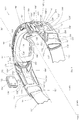
- the goggle 100 comprises a body 102 having ends 101, 103, a lens 104 installed in the body, a plurality of body extension members 106, 108 and an elastic, stretchy, textile strap portion 110 having ends 113, 115.
- the goggle 100 also preferably comprises a flexible, spongy, foam interface peripheral member 91 attached around a posterior periphery 96 of the goggle body 102.
- the foam interface member 91 is for interfacing with the use's face and the semi-rigid, lightweight plastic, or other suitable material, such as silicone, posterior portion 96 of the anterior goggle body 102 for interfacing with the lens 104.
- the posterior flexible and spongy portion 91 of the body 102 engages the user's face around the user's eyes and on the bridge of the user's nose at 97, while the anterior periphery member 103 provides a base or foundation upon which the lens 104 is engaged.
- the goggle body 102 may be provided with conventional ventilation ports 94 in the anterior portion 103 of the goggle body.
- the lens 104 of the present invention is preferably easily interchangeable as shown and described in that patent application.
- the lens 104 may be a clear lens, or a tinted lens as known in the art, the lens preferably having a clear anti-fog resistive coating 174 on an inner surface of the lens, the coating further being protected with a protective layer, or double-lens construction, to protect the anti-fog surface from being scratched off.
- the anti-fog resistive coating 174 preferably comprises an Indium Tin Oxide (ITO) compound that may be sprayed, deposited with a known ion-sputtering technique, painted or otherwise layered or applied.
- the film heating member 174 may be comprised of another material designed in the form of a resistive element that generates heat when connected to an electrical circuit.
- the goggle 100 further comprises a lens frame, or bezel 170, upon which the lens 104 is retained, as for example with adhesive, and the bezel further comprises engagement, e.g., a tongue and groove engagement means, or cap and ridge engagement means as described in the aforementioned patent application to McCulloch et al. Still further, the lens 104 / bezel 170 comprises interconnection means, for example snaps, hooks, silicone nubs or latches, both operative to engage and secure connection with a lens contact portion 172, if any, of the goggle 100, for interconnecting a heating element portion 174 on the inner surface of the lens 104 with the batteries 159.
- interconnection means for example snaps, hooks, silicone nubs or latches
- the lens 104 is easily interchangeable, a user may have multiple such lens 104 / bezel 170 combinations, each such lens comprising alternate tinted lens surfaces of varying colors and/or degree of tint, again either with or without anti-fog resistive coating thereon.
- This feature provides that either anti-fog or non-anti-fog lenses may be used with the goggle 100 of the invention without damaging the system or even reducing battery life.
- the electrical system of the goggle 100 is preferably a low-power system which enables safe usage of the goggle with a heated lens 104, or with a non-heated lens 104, in the goggle.
- This feature makes use of the goggle more care-free and flexible, as whether the battery is in use, or not, the user is encouraged in choosing a goggle 100 that suits the weather, terrain, and lighting conditions of the moment.
- the body extension member 106 comprises first and second ends, 105, 107 and inner and outer surfaces 93 and 120, respectively.
- the body extension member 108 comprises first and second ends 109, 111 and inner and outer surfaces 95 and 122, respectively.
- the body extension members 106, 108 comprise in part what would otherwise be side portions of a strap of a conventional goggle. In other words, the body extension members 106, 108 are in the same location relative to a user's head as would the side portions of a strap of a conventional goggle.
- the first end 105, 109 of each body extension member 106, 108 extends from a corresponding end 101, 103, respectively, of the goggle body 102.
- accordion-type, serpentine, reticulation channel means 117, 121 may be employed between the goggle body 102 and each body extension member 106, 108, respectively, in order to ensure sufficient flexibility to the strap-type function of each body extension member to enable easy adaptation of the goggle to differently-shaped users and their various head and helmet shapes and sizes.
- the second end 107, 111 of each body extension member 106, 108 is attached to corresponding ends 113, 115, respectively, of the textile strap portion 110 of the strap (comprised of each extension member 106, 108 and the textile portion 110).
- Such attachment may be accomplished by looping the ends 113, 115 of the strap 110 around pins (not shown) embedded into the second ends 107, 111 of the body extension members 106, 108, or other means of interconnecting such dissimilar elements known in the art, such as by stitching 99.
- the goggle 100 further comprises a plurality of battery pods 156.
- Each battery pod 156 comprises a container 160 that is sealed around the battery 159 inside.
- An upper surface 166 of the battery pod 156 may have ribs 167 thereon to enable easier gripping of the battery pod and to also provide gripping of the pod to a user's helmet, cap or head, in the case where the container 160 may be made of hard plastic, but the ribs 167 may be made of silicone that is capable of gripping and conforming more easily to a slightly curved helmet surface.
- Each battery pod 156 further comprises a battery protection circuit 162 for the purpose of protecting the rechargeable batteries from sudden, short-circuit, rapid discharge. As shown in FIG. 5 , the container 160 is cut at the top to provide a view to the battery 159 inside.
- Each body extension member 106, 108 further comprises an inner surface 116, 118, respectively, each inner surface being comprised partially of an inner surface 166 of battery pods 156 when such are retained within each extension member, each extension member further comprising the outer molded, stylized, aerodynamic surfaces 120, 122.
- On the inner surfaces 93 and 116 of the body extension member 106 there is a raised area 210 which may be provided with special grippability of silicone material to facilitate retention of the body extension member 106' on a user's helmet.
- a raised area 212 which may be provided with special grippability of silicone material to facilitate retention of the body extension member 106 on the user's helmet, hat or head.
- Surfaces 210 and 212 may be higher in profile (closer to the helmet) than surfaces 116, 118, respectively, or the opposite may be true, where surfaces 210, 212 may be lower in profile than surfaces 116, 118, with surfaces 116, 118 having more grippable material.
- each body extension member 106, 108 is a battery pod cavity 124, 126, respectively, defined centrally within its corresponding body extension member.
- the inside of each battery pod cavity 124, 126 comprises a forward surface 128, 130, respectively, a rearward surface 132, 134, respectively, an upper surface 136, 138, respectively, a lower surface 140, 142, respectively, and an outer (still inside) surface 144, 146, respectively.
- An anterior surface portion of the "pod" looking outer surface 120 opposite cavity 124 is comprised of angled aerodynamic and aesthetically designed surfaces 198, and a posterior surface portion of the retainer 124 is comprised of angled aerodynamic and aesthetically designed surfaces 200.
- an anterior surface portion of the cassette-like retainer 126 is comprised of angled aerodynamic and aesthetically designed surfaces 202
- a posterior portion of the retainer 126 is comprised of angled aerodynamic and aesthetically designed surfaces 204.
- the pod aspect of the battery pod 156 is introduced and reinforced in that the cassette-like cavity's 124, 126 are reinforced with angular support members 206, 208, respectively, which not only give stability to the preferably silicone, TPU or other rigid structure, solid durometer plastic material, of the cassette or outer pod, but also lends to the aesthetic and aerodynamic functionality and appearance of the cassette.
- Each battery pod cavity 124, 126 is designed to be symmetrical about a y-z plane as shown in FIGS. 3 and 10 .
- Each cavity 124, 126 is further defined by a lip, or edge, 152, 154, respectively, located around the inner periphery of the opening of each cavity, for retaining a tongue, or retaining member, 168 of each battery pod within the cavity.
- each cavity 124, 126 there is thumb, or other finger, slot 180, 182 for allowing a user to insert his or her finger in the slot to bias the battery pod 156 against the contacts 147, 148, 149, 150, respectively, and to enable clearance of the tongue 158 of each battery pod from being held by a rearward, or posterior, portion of lip 152, 154 of each cavity, respectively.
- Each battery pod 156 has positive and negative contacts, 158, 162, respectively, for connecting the battery 159 within the battery pod to circuitry 164 of the goggle outside the battery pod.
- the battery pods 156 are comprised of a relatively rigid or solid durometer plastic material, such as TPU or silicone, sealed in water-proof fashion around the battery 159, and therefore the battery is sealed against water intrusion.
- each cavity 124, 126 is such that water intrusion is minimized, since the preferably silicone or TPU lip 152, 154 of each cavity 124, 126 extends around the periphery of the edge 168 of the battery pod 156, the silicone lip making a seal on the tongue 168, and since the cavity is on the inside surface of each extension member 106, 108, the molded outer surface 120, 122 of each extension member, accommodates the battery pod in a sealed fashion.
- the goggle body 102, 103 and the "strap" portions are preferably integrated into, or comprised of, a single unit which extends from the goggle body 102/103 to a position that is adapted to be well over, and even alternatively behind, the ears of a user, as would a conventional strap of a goggle.
- the purpose of these body extension members 106, 108 is for retaining the batteries 159 in their battery pods 156 of a capacity necessary for powering the goggle for extended periods of time.
- This preferred embodiment enables not only a better looking and weight-balanced goggle 100, but a more functionally capable goggle in that the heavier batteries 159 able to be supported by such a structure will not sag as otherwise would a conventional strap sag under the increased battery weight or otherwise would be cumbersome to the user.
- this aspect of the invention enables a preferred inner opening battery cavity 124, 126 structure (i.e., body extension members 106, 108 and the surfaces 128, 132, 134, 138, 144 and surfaces 130, 134, 138, 142, 146, respectively) which is well-sealed in integral silicone that not only grips the user's helmet on its inner surface (including inner surfaces 166 of the battery pod 156, surfaces 93, 95 and surfaces 116, 118 of the extension members 106, 108, respectively) to support the added battery weight, but also seals the system against moisture intrusion.
- a preferred inner opening battery cavity 124, 126 structure i.e., body extension members 106, 108 and the surfaces 128, 132, 134, 138, 144 and surfaces 130, 134, 138, 142, 146, respectively
- Each battery 159 may be suitably comprised of a lithium-ion, or lithium-poly, battery conventionally used in cell phones.
- the battery 159 is rechargeable within the battery pod 156, the battery pod container 160 preferably being made of plastic resin, or silicone, with the positive and negative external contacts 158, 162, respectively, on the battery pod providing electrical contact through the container external of the battery pod for supplying power to the goggle 100.
- Goggle 100 further comprises goggle circuit wiring 164, as further shown in FIG. 4 , for carrying power from the batteries 159 via the contacts 158, 162 and contacts 147, 148, 149, 150.
- Circuit wiring 164 preferably comprises a series circuit having contacts as previously described for connection to the battery 159 power source, the circuit further comprising optional contacts for interconnecting the circuit wiring 164, and hence the batteries 159, with the resistive heating element 174 via contacts 172 between the resistive heating element and the circuit. Since the goggle is to be substantially symmetrical on either side of the y-z plane shown in FIG. 3 , this means that the cavity contacts 147, 148, 149, 150 are configured so that the same polarity contact is on the inside (relative to the y-z plane) in each battery pod cavity 124, 126 and the same polarity contact is on the outside (relative to the y-z plane) in each battery pod cavity.
- the outer contact 150 is designated as the negative contact
- the inner contact 149 is designated as the positive contact
- the outer contact 148 is designated as the negative contact
- the inner contact 147 is designated as the positive contact.
- the circuit wiring 164 in the goggle 100 is preferably wired in series as shown in FIG. 4 with opposite poles of each battery being interconnected and with the contacts to the other electronics, such as the heating element 174 of lens 104, being interposed between one of these opposite pole interconnections.
- a more complete electrical diagram for wiring of electronics in the goggle may be found in US Patent No.
- the goggle 100 also preferably comprises a charging port 176 and charging circuit that may be interconnected with circuit wiring 164. Accordingly, the batteries 159 may be charged via the charging port 176 on an under surface of the goggle 100.
- the charging port 176 may be plugged with a suitable plug (not shown) when not in use, to prevent the intrusion of moisture into the electronic system.
- a processor 178 for the purpose of controlling electronic functions of the goggle, such as video capture, GPS functionality, indicator lights, heads-up display and/or heating, etc.
- Electrical circuitry 164 may advantageously be like that shown in that application with contacts (e.g., buss bars) on the lens being similar to those shown and described and with the circuitry 164 running through the goggle body 102/103 to interconnect the resistive-film heating means 174, the battery 159, the USB, or other power connection, charging receptacle 176, the on/off button 188 and any other power level adjustments or other electronic controls as will be apparent to those of skill in the art of electronics.
- contacts e.g., buss bars
- the goggle body 102/103 and extension members may be made of a plastic resin, silicone rubber or other material suitably flexible for conforming to the contours of a user's head, while also having sufficient rigidity to appropriately retain in substantially fixed position the weight of the battery pods 156 and the lens 104.
- the goggle lens 104 may be made of an optical quality polycarbonate plastic material.
- the battery pods 156 may be made of silicone rubber or other sufficiently rigid material to ensure good frictional or other retention of the battery pod in the battery pod cavity 124, 126, to ensure good wear characteristics and to ensure good gripping of a user's helmet.
- the grippability of the silicone on a user's helmet is an important factor in retaining the goggle on the helmet without sagging or sliding down during exertion of activity and encounter of bumps and jolts commonly encountered in snowboarding or skiing.
- the textile strap portion 110 may comprise a conventional adjustable elastomeric strap that is stretchy, and yet resilient, so as to allow comfortable retention of the goggle 100 on the user's head or a helmet.
- the length of the strap 110 is adjustable via adjustment members 184, 186.
- the goggle 100 also preferably comprises at least an on-off switch 188 (in reality this is typically an on and very low power switch) for allowing power to the goggle lens 104 and/or other goggle electronics.
- on-off switch 188 in reality this is typically an on and very low power switch
- other heating power controls such as a power level control switch, and a battery level indicator switch, as described more in detail in US Patent Application 13/587,908 to McCulloch et al. , may be incorporated into the electronics and power system described herein.
- switching and control systems 178 may be provided for as part of the present goggle 100 for enhanced functionality of a GPS system, a video capturing system, a sound system, or other electronic device, as such switching is described in the prior art. Such switching and control systems 178 may be run off of the circuit wiring 164 and battery power and control of the present goggle 100.
- any other electronics of the goggle 100 may be switched on with the main power switch 188, whereas other controls may be implemented, for example to set the power level of the heating element of the lens to zero level as may be desired and as further described in US Patent No. 8,566,962 B2 , for PWM Heating System for an Eyeshield, to Cornelius.
- a battery-strength indicator 190, and a heat, or power level, indicator 192 may be displayed preferably within the goggle 100 to the user of the goggle.
- Depressing the on/off button 100 again may be implemented to turn off the heat, or more accurately reduce it to an extremely low power state. After a short time, preferably, the indicators 190, 192 turn off so as to not unduly distract the user.
- the circuitry 164 also interconnects a standard USB or other power connector charging receptacle 176, the battery 159, logic for controlling power on/off, power level increase/decrease, power level indication, and battery level indication using electric light pipes, for example.
- Goggle 100' comprises a multi-pod, symmetrically-balanced, goggle-strap-mounted power supply system.
- the goggle 100' comprises a body 102' having ends 101', 103', a lens 104' installed in the body, a plurality of body extension members 106', 108' and an elastic, stretchy, textile strap portion 110' having ends 113', 115'.
- the goggle 100' also preferably comprises a flexible, spongy, foam interface peripheral member 91' attached around a posterior periphery 96' of the goggle body 102'.
- the foam interface member 91' is for interfacing with the use's face and the posterior portion 96' of the anterior portion 102' of the goggle body, and is for interfacing with the lens 104'.
- the posterior flexible and spongy portion 91' of the body 102' engages the user's face around the user's eyes and on the bridge of the user's nose at 97', while the anterior periphery body member 102' provides a base or foundation upon which the lens 104' is engaged.
- the goggle body 102' may be provided with conventional ventilation ports 94' in the anterior portion of the goggle body.
- US Patent Application Serial No. 13/587,908 for Goggle with Easily Interchangeable Lens that is Adaptable for Heating to Prevent Fogging, to McCulloch et al., discloses an interchangeable series of lenses having varying types of resistive element, or resistive film, heating elements thereon, or alternatively having no heating element on the lens at all.
- the goggle of this alternate variant set forth in the present application may, likewise, employ similar lens types.
- the battery pods 156' would be useful to power other electronic functions of the goggle 100', such as GPS, video, audio sound, heads-up display, and other electronic functions.
- the lens 104' of the present invention is preferably easily interchangeable as shown and described in that patent application.
- the lens 104' may be a clear lens, or a tinted lens as known in the art, and preferably has a clear anti-fog resistive coating 174' on an inner surface of the lens, the coating further being protected with a protective layer, or double-lens construction, to protect the anti-fog surface from being scratched off.
- the anti-fog resistive coating 174' preferably comprises an Indium Tin Oxide (ITO) compound that may be sprayed, deposited with a known ion-sputtering technique, painted or otherwise layered or applied.
- the film heating member 174' may be comprised of another material designed in the form of a resistive element that generates heat when connected to an electrical circuit.
- the goggle 100' further comprises a lens frame, or bezel 170', upon which the lens 104' is retained, as for example with adhesive, and the bezel further comprises engagement, e.g., a tongue and groove engagement means, or cap and ridge engagement means as described in the aforementioned patent application to McCulloch et al. Still further, the lens 104' / bezel 170' comprises interconnection means, for example snaps, hooks, silicone nubs or latches, both operative to engage and secure connection with a lens contact portion 172', if any, of the goggle 100', for interconnecting a heating element portion 174' on the inner surface of the lens 104' with the batteries.
- interconnection means for example snaps, hooks, silicone nubs or latches
- the lens 104' is easily interchangeable, a user may have multiple such lens 104' / bezel 170' combinations, each such lens comprising alternate tinted lens surfaces of varying colors and/or degree of tint, again either with or without anti-fog lenses may be used with the goggle 100' of the invention without damaging the system or even reducing battery life.
- the electrical system of the goggle 100' is preferably a low-power system which enables safe usage of the goggle with a heated lens 104', or with a non-heated lens 104', in the goggle. This feature makes use of the goggle more care-free and flexible, as whether the battery is in use, or not, the user is encouraged in choosing a goggle 100' that suits the weather, terrain, and lighting conditions of the moment.
- the body extension member 106' comprises first and second ends, 105', 107' and inner and outer surfaces 93' and 120', respectively.
- the body extension member 108 comprises first and second ends 109', 111' and inner and outer surfaces 95' and 122', respectively.
- the body extension members 106', 108' comprise in part what would otherwise be side portions of a strap of a conventional goggle. In other words, the body extension members 106', 108' are in the same location relative to a user's head as would the side portions of a strap of a conventional goggle.
- the first end 105', 109' of each body extension member 106', 108' extends from a corresponding end 101', 103', respectively, of the goggle body 102'.
- accordion-type, serpentine, reticulation channel means 117', 121' may be employed between the goggle body 102' and each body extension member 106', 108', respectively, in order to ensure sufficient flexibility to the strap-type function of each body extension member to enable easy adaptation of the goggle to differently-shaped users and their various head and helmet shapes and sizes.
- the second end 107', 111' of each body extension member 106', 108' is attached to corresponding ends 113', 115', respectively, of the textile strap portion 110' of the strap (comprised of each extension member 106', 108' and the textile portion 110').
- Such attachment may be accomplished by looping the ends 113', 115' of the strap 110' around pins (not shown) embedded into the second ends 107', 111' of the body extension members 106', 108', or other means of interconnecting such dissimilar elements known in the art, such as by stitching 99'.
- the goggle 100' further comprises a plurality of battery pods 156'.
- Each battery pod 156' comprises a container 160' that is sealed around the battery inside.
- Each battery pod 156' further comprises a battery protection circuit (not shown) for the purpose of protecting the rechargeable batteries from sudden, short-circuit, rapid discharge.
- Each body extension member 106', 108' further comprises an inner surface 116', 118', respectively, each extension member further comprising the outer molded, stylized, aerodynamic surfaces 120', 122'.
- a battery pod cavity 124', 126' Within, and defined so as to be accessible from the exterior of each body extension member 106', 108' is a battery pod cavity 124', 126', respectively, defined centrally within its corresponding body extension member.
- the inside of each battery pod cavity 124', 126' comprises a forward surface 128', 130', respectively, a rearward surface 132', 134', respectively, a lower surface 140', 142', respectively, and an inner surface 144', 146', respectively.
- Each battery pod cavity 124', 126' is designed to be symmetrical about a y-z plane as shown in FIG. 7 .
- Each cavity 124', 126' is further defined by a plurality of lips, or edges, 152', 154', respectively, located around the inner periphery of the opening of each cavity, for retaining back edges 153 of the battery pod 156' to retain the battery pod within the cavity.
- surfaces 120', 128', 132', 140', 144', and lips 152' define a cassette-like retainer, otherwise known as cavity 124', in which the battery pod 156' is retained.
- An anterior surface portion of the cassette-like retainer 124' is comprised of angled aerodynamic and aesthetically designed surfaces 198', and a posterior surface portion of the retainer 124' is comprised of angled aerodynamic and aesthetically designed surfaces 200'.
- surfaces 122', 130', 134', 142', 146' and lips, or edges, 154' define another cassette-like retainer, otherwise known as cavity 126', in which the battery pod 156' is retained.
- An anterior surface portion of the cassette-like retainer 126' is comprised of angled aerodynamic and aesthetically designed surfaces 202', and a posterior portion of the retainer 126' is comprised of angled aerodynamic and aesthetically designed surfaces 204'.
- the pod aspect of the battery pod 156' is introduced and reinforced in that the cassette-like cavity's 124', 126' are reinforced with angular support members 206', 208', respectively, which not only give stability to the preferably TPU or silicone structure of the cassette, but also lends to the aesthetic and aerodynamic functionality and appearance of the cassette.
- a raised area 210' which may be provided with special grippability of silicone material to facilitate retention of the body extension member 106' on a user's helmet.
- a raised area 212' which may be provided with special grippability of silicone material to facilitate retention of the body extension member 106' on the user's helmet.
- Surfaces 210' an 212' may be higher in profile (closer to the helmet) than surfaces 116', 118', respectively, or the opposite may be true, where surfaces 210', 212' may be lower in profile than surfaces 116', 118', with surfaces 116', 118' having more grippable material.
- each battery pod 156' there are upper and lower thumb, or finger, catches 194 for allowing a user to grip the battery pod to press the battery pod into a cavity 124', 126', or alternatively to remove the battery pod from a cavity.
- Adjacent each of these catches 194 are up and down arrow indicia 196, indicating the direction in which the battery pod 156' may be inserted into, and removed from, a cavity 124', 126'.
- a user is enabled in using his or her finger on the catch 194 to bias the battery pod 156' into a respective cavity 124', 126' and against the contacts 147', 148', or 149', 150'.
- Each battery pod 156' also comprises a raised area 196 on an outside surface 167' of the battery pod. Insertion of the battery pod 156' into a cavity 124', 126' by a user proceeds until an edge portion of the outside surface 167' hits lower lip 152', 154', respectively. The battery pod 156' is held in place and sealed against moisture intrusion by a rearward, or posterior, portion of lip 152', 154' of each cavity, respectively.
- Each battery pod 156' has positive and negative contacts, 158', 162', respectively, for connecting the battery within the battery pod to circuitry 164' of the goggle outside the battery pod.
- the battery pods 156' are comprised of plastic resin or silicone sealed in water-proof fashion around the battery, and therefore the battery is sealed against water intrusion.
- the design of each cavity 124', 126' is such that water intrusion is minimized into the cavity, since the preferably silicone or TPU lip 154' of each cavity 124', 126' extends around the periphery of the edge 168' of the battery pod 156, the silicone lip making a seal on the edge 168' to prevent excess water from getting into the cavities. Water intrusion may also be further prevented within the cavities 124', 126' with a liftable flap (essentially an extension of lips 152', 154').
- the goggle body 102', 103' and the "strap" portions are preferably integrated into, or comprised of, a single unit which extends from the goggle body 102'/103' to a position that is adapted to be well over, and even alternatively behind, the ears of a user, as would a conventional strap of a goggle.
- the purpose of these body extension members 106', 108' is for retaining the battery pods 156' of a capacity necessary for powering the goggle for extended periods of time.
- this aspect of the invention enables a cassette-like opening battery cavity 124', 126' structure (i.e., body extension members 106', 108' and the surfaces 128', 132', 134', 138', 144' and surfaces 130', 134', 138', 142', 146', respectively) which is well-sealed in integral silicone that not only grips the user's helmet on its inner surface (including surfaces 93', 95' and surfaces 116', 118', respectively, of the extension members 106', 108') to support the added battery weight, but also seals the system against moisture intrusion.
- a cassette-like opening battery cavity 124', 126' structure i.e., body extension members 106', 108' and the surfaces 128', 132', 134', 138', 144' and surfaces 130', 134', 138', 142', 146', respectively
- Each battery pod 156' may be suitably comprised of a lithium-ion, or lithium-poly, battery conventionally used in cell phones.
- the battery is rechargeable within the battery pod 156', the battery pod container 160' preferably being made of plastic resin, or silicone, with the positive and negative external contacts 158', 162', respectively, on the battery pod providing electrical contact through the container external of the battery pod for supplying power to the goggle 100'.
- Goggle 100' further comprises goggle circuit wiring 164', as further shown in FIGS. 6 , 7 and 9 , for carrying power from the battery pods 156' via the contacts 158', 162' and contacts 147', 148', 149', 150'.
- Circuit wiring 164' preferably comprises a series circuit having contacts as previously described for connection to the battery pod 156 power sources, the circuit further comprising optional contacts for interconnecting the circuit wiring 164', and hence the battery pods 156', with the resistive heating element 174' via contacts 172' between the resistive heating element and the circuit. Since the goggle is to be substantially symmetrical on either side of the y-z plane shown in FIG. 7 , this means that the cavity contacts 147', 148', 149', 150' are configured so that the same polarity contact is on the inside (relative to the y-z plane) in each battery pod cavity contacts 172' between the resistive heating element and the circuit.
- the goggle is to be substantially symmetrical on either side of the y-z plane shown in FIG. 7 , this means that the cavity contacts 147', 148', 149', 150' are configured so that the same polarity contact is on the inside (relative to the y-z plane) in each battery pod cavity 124', 126' and the same polarity contact is on the outside (relative to the y-z plane) in each battery pod cavity. It doesn't matter which polarity contact is on the inside and which polarity contact is on the outside, just that they are consistently oriented to the battery pod 154' configuration. Thus, for example, as shown in FIGS.
- the outer contact 150' is designated as the negative contact
- the inner contact 149' is designated as the positive contact
- the outer contact 148' is designated as the negative contact
- the inner contact 147' is designated as the positive contact.
- the circuit wiring 164' in the goggle 100' is preferably wired in series as shown in FIG. 11 with opposite poles of each battery being interconnected and with the contacts to the other electronics, such as the heating element 174' of lens 104', being interposed between one of these opposite pole interconnections.
- the goggle 100' also preferably comprises a charging port 176' and charging circuit that may be interconnected with circuit wiring 164'. Accordingly, the battery pods 156' may be charged via the charging port 176', shown on an under surface of the goggle 100'. It will be appreciated that the charging port of the goggle may be located on any convenient surface of the goggle body with due consideration being given to sealing the port. Or alternatively, the goggle battery may be charged by placing it on a charging mat as is known in the art.
- the charging port 176' may be as video capture, GPS functionality, indicator lights, heads-up display and/or heating, etc.
- the electrical circuitry 164' may advantageously be like that shown in that application to Cornelius with contacts (e.g., buss bars) on the lens being similar to those shown and described and with the circuitry 164' running through the goggle body 102'/103' to interconnect the resistive-film heating means 174', the battery pod 156', the USB, or other power connection, charging receptacle 176', the on/off button 188' and any other power level adjustments or other electronic controls as will be apparent to those of skill in the art of electronics.
- contacts e.g., buss bars
- the goggle body 102'/103' and extension members may be made of a plastic resin, silicone rubber or other material such thermal plastic urethane, sometimes called TPU, that is suitably flexible for conforming to the contours of a user's head, while also having sufficient rigidity to appropriately retain in substantially fixed position the weight of the battery pods 156' and the lens 104'.
- the goggle lens 104' may be made of an optical quality polycarbonate plastic material.
- the battery pods 156' may be made of plastic resin, silicone rubber or other sufficiently rigid material to ensure good frictional or other retention of the battery pod in the battery pod cavity 124', 126'.
- the grippability of the silicone on a user's helmet is an important factor in retaining the goggle on the helmet without sagging or sliding down during exertion of activity and encounter of bumps and jolts commonly encountered in snowboarding or skiing.
- the textile strap portion 110' may comprise a conventional adjustable elastomeric strap that is stretchy, and yet resilient, so as to allow comfortable retention of the goggle 100' on the user's head or a helmet.
- the length of the strap 110' is adjustable via adjustment members 184', 186'.
- the goggle 100' also preferably comprises at least an on-off switch 188' (in reality this is typically an on and very low power switch) for allowing power to the goggle lens 104' and/or other goggle electronics.
- other heating power controls such as a power level control switch, and a battery level indicator switch, as described more in detail in US Patent Application 13/587,908 to McCulloch et al. , may be incorporated into the electronics and power system described herein.
- switching and control systems 178' may be provided for as part of the present goggle 100' for enhanced functionality of a GPS system, a video capturing system, a sound system, or other electronic device, as such switching is described in the prior art. Such switching and control systems 178' may be run off of the circuit wiring 164' and battery power and control of the present goggle 100'.
- any other electronics of the goggle 100' may be switched on with the main power switch 188', whereas other controls may be implemented, for example to set the power level of the heating element of the lens to zero level as may be desired and as further described in US Patent No. 8,566,962 B2 , for PWM Heating System for an Eyeshield, to Cornelius.
- a battery-strength indicator 190', and a heat, or power level, indicator 192' may be displayed preferably within the goggle 100' to the user of the goggle.
- Depressing the on/off button 188' again may be implemented to turn off the heat, or more accurately reduce it to an extremely low power state. After a short time, preferably, the indicators 190', 192' turn off so as to not unduly distract the user.
- the circuitry 164' also interconnects a standard USB or other power connector charging receptacle 176', the battery pod 156', logic for controlling power on/off, power level increase/decrease, power level indication, and battery level indication using electric light pipes, for example.
Landscapes
- Health & Medical Sciences (AREA)
- Engineering & Computer Science (AREA)
- Otolaryngology (AREA)
- General Health & Medical Sciences (AREA)
- Chemical Kinetics & Catalysis (AREA)
- Electrochemistry (AREA)
- General Chemical & Material Sciences (AREA)
- Veterinary Medicine (AREA)
- Public Health (AREA)
- Ophthalmology & Optometry (AREA)
- Biomedical Technology (AREA)
- Heart & Thoracic Surgery (AREA)
- Vascular Medicine (AREA)
- Life Sciences & Earth Sciences (AREA)
- Animal Behavior & Ethology (AREA)
- Chemical & Material Sciences (AREA)
- Microelectronics & Electronic Packaging (AREA)
- Manufacturing & Machinery (AREA)
- Battery Mounting, Suspending (AREA)
Claims (15)
- Batteriebetriebene Brille (100), die eine strombetriebene Funktion in der Brille (100) durchführen kann, umfassend:einen Brillenkörper (102) mit Verdrahtung darin und einem ersten und zweiten Ende (101,103);eine Linse (104), die in dem Brillenkörper (102) gehalten wird;ein erstes und zweites Verlängerungselement (106, 108), die mit dem Brillenkörper (102) verbunden sind, wobei jedes Verlängerungselement (106, 108) ein erstes Ende (105, 109), ein zweites Ende (107, 111), eine Innenfläche (93, 95) und eine Außenfläche (120, 122) aufweist, wobei jedes Verlängerungselement (106, 108) eine Verdrahtung (164) darin aufweist, die mit der Verdrahtung (164) in dem Brillenkörper (102) verbunden ist, um eine Batterie (159) mit der Verdrahtung (164) im Brillenkörper (102) zu verbinden, wobei jedes Verlängerungselement (106, 108) wenigstens einen konkaven geformten Hohlraum (124, 126) definiert, der zu einer von der Innenfläche (93, 95) des Verlängerungselements (106, 108) und der Außenfläche (120, 122) des Verlängerungselements (106, 108) hin offen ist, und in dem Hohlraum definierte Kontakte (147, 148, 149, 150) zum Verbinden der Batterie (159) mit der Verdrahtung (164) im Verlängerungselement (106, 108) aufweist, wobei das erste Ende (105, 109) jedes Verlängerungselements (106, 108) mit einem jeweiligen ersten und zweiten Ende (101, 103) des Brillenkörpers (102) verbunden ist, wobei der Brillenkörper (102) und die Verlängerungselemente (106, 108) einstückig verbunden und aus einem Material hergestellt sind, das ausreichend flexibel ist, um sich an die Konturen eines Kopfs oder Helms eines Benutzers anzupassen;einen Riemenabschnitt (110) mit einem ersten und zweiten Ende (113, 115), wobei das erste Ende (113) des Riemenabschnitts (110) mit dem zweiten Ende (107) des ersten Verlängerungselements (106) verbunden ist und das zweite Ende (115) des Riemenabschnitts (110) mit dem zweiten Ende (111) des zweiten Verlängerungselements (108) verbunden ist;eine Vielzahl von Batterien (159);eine Vielzahl von Batteriehülsen (156), wobei jede Batteriehülse (156) einen Behälter (160) umfasst, der wenigstens eine der Batterien (159) enthält und dazu angepasst ist, lösbar in einem beliebigen Hohlraum (124, 126) eines beliebigen der Verlängerungselemente (106, 108) gehalten zu werden, wobei jede Batteriehülse (156) dazu angepasst ist, einen Kontakt zwischen wenigstens einer der Batterien (159) in dem Behälter und den Kontakten (147, 148, 149, 150) in einem beliebigen Hohlraum (124, 126) eines beliebigen der Verlängerungselemente (106, 108) bereitzustellen, wodurch die Übertragung von Leistung von den Batterien (159) zum Betreiben der Brille (100) aktiviert wird.
- Brille (100) nach Anspruch 1, umfassend jeweils akkordeonartige, gewundene Vernetzungskanalmittel (117, 121) zwischen dem Brillenkörper (102) und jedem Körperverlängerungselement (106, 108), um dem Verlängerungselement für eine riemenartige Funktion Flexibilität zu verleihen.
- Brille (100) nach Anspruch 1 oder 2, wobei jedes Verlängerungselement (106, 108) in lateraler und Querrichtung semiflexibel ist, wobei jedes Verlängerungselement (106, 108) auch gegenüber Dehnen in einer Längsrichtung beständig ist.
- Brille (100) nach Anspruch 3, wobei jedes Verlängerungselement (106, 108) und der Brillenkörper (102) aus zusammenhängendem Silikon hergestellt sind.
- Brille (100) nach Anspruch 1, wobei jede Batterie (159), jede Batteriehülse (156) und jeder Hohlraumkontakt (147, 148, 149, 150) ferner ein Paar Kontakte umfasst, die Kontakte (158, 162) positiver und negativer Polarität umfassen, und wobei jeder Hohlraum (124, 126) und jedes Paar Hohlraumkontakte (147, 148, 149, 150) in einem entsprechenden besagten Verlängerungselement (106, 108) angeordnet sind, wobei jeder Hohlraum (124, 126) und jedes Paar Hohlraumkontakte (147, 148, 149, 150) symmetrisch um eine Querebene durch den Brillenkörper (102) angeordnet und derart orientiert sind, dass sich der Hohlraum (124, 126) zur Innenseitenfläche (93, 95) jedes Verlängerungselements (106, 108) hin öffnet und jeder positive Hohlraumkontakt (149) und jeder negative Hohlraumkontakt (150) symmetrisch um die Querebene orientiert sind, wobei jede Batteriehülse (156) gleich ist und dazu in der Lage ist, lösbar in einem beliebigen der Hohlräume (124, 126) in den Verlängerungselementen (106, 108) gehalten zu werden.
- Batteriebetriebene Brille (100) nach Anspruch 1, konfiguriert als eine mit zweifacher Batteriehülse betriebene Brille, die dazu in der Lage ist, die Linse (104) der Brille (100) zu erwärmen, wobei:die Linse (104) ein Widerstandsheizelement (174) daran aufweist, das mit der Verdrahtung (164) im Brillenkörper (102) verbunden ist; wobei das erste und zweite Verlängerungselement (106, 108) einstückig mit dem Brillenkörper (102) verbunden sind, und der wenigstens eine konkave geformte Hohlraum (124, 126) zur Innenfläche (93, 95) des Verlängerungselements (106,108) hin offen ist; und wobeidie Brille (100) zwei Batteriehülsen (156) zur Übertragung von Leistung von den Batterien (159) an die Brille (100) umfasst, um das Erwärmen der Brillenlinse (104) zu ermöglichen.
- Brille (100) nach Anspruch 6, wobei jedes Verlängerungselement (106, 108) und das Riemenelement (110) aus einstückigem Silikongummi gebildet sind.
- Brille (100) nach Anspruch 1 oder Anspruch 7, wobei jedes Verlängerungselement (106, 108) ferner einen Kanal (117, 121) für die Verdrahtung (164) definiert.
- Brille (100) nach Anspruch 6, wobei jede Batterie (159), jede Batteriehülse (156) und jeder Hohlraumkontakt (147, 148, 149, 150) ferner ein Paar Kontakte umfassen, die Kontakte (158, 162) positiver und negativer Polarität umfassen, und wobei jeder Hohlraum (124, 126) und jedes Paar Hohlraumkontakte (147, 148, 149, 150) in einem entsprechenden besagten Verlängerungselement (106, 108) angeordnet sind, wobei jeder Hohlraum (124, 126) und jedes Paar Hohlraumkontakte (147, 148, 149, 150) symmetrisch um eine Querebene durch den Brillenkörper (102) angeordnet und derart orientiert sind, dass jeder positive Hohlraumkontakt (149) und jeder negative Hohlraumkontakt (150) symmetrisch um die Querebene orientiert sind, wobei jede Batteriehülse (156) gleich ist und dazu in der Lage ist, lösbar in einem beliebigen der Hohlräume (124, 126) in den Verlängerungselementen (106, 108) gehalten zu werden.
- Brille (100) nach Anspruch 6, wobei die gegenüberliegenden Hohlräume (124, 126) symmetrisch in ihre jeweiligen Verlängerungselemente (106, 108) eingeformt sind, derart, dass eine einzelne Art von Batteriehülse (156) in jedem Hohlraum (124, 126) an beiden Verlängerungselementen (106, 108) verwendet werden kann, wobei Batteriehülsenkontakte (158, 162) jeder Batteriehülse (156) mit den Kontakten (147, 148, 149, 150) jedes Batteriehohlraums (124, 126) verbunden sind, derart, dass die Batteriekontakte (158, 162) und die Hohlraumkontakte (147, 148, 149, 150) in einem vorderen Abschnitt (128, 130) jedes Batteriehohlraums (124, 126) angeordnet sind, der dem Brillenkörper (102) am nächsten ist.
- Brille (100) nach Anspruch 10, wobei die Verdrahtung (164) der Brille (100) dazu hergestellt ist, eine Reihenverbindung der Batterien (159) zu ermöglichen, wobei die Hohlraumkontaktpole in ihrer Polarität symmetrisch um eine Querebene durch den Brillenkörper (102) umgekehrt sind, um die Verwendung einer einzelnen Art von Hülse (156) in um die Querebene symmetrischer Weise und in jedem sich nach innen öffnenden Hohlraum (124, 126) in jedem Verlängerungselement (106, 108) zu ermöglichen.
- Brille (100) nach Anspruch 6, ferner umfassend eine Ladevorrichtung, und wobei die Batterien (159) wiederaufladbar sind, während sie sich in den Batteriehülsen (156) befinden.
- Brille (100) nach Anspruch 6, ferner umfassend einen Ladeanschluss (176), der zum Anschließen der Brille (100) an eine Standardwechselstromsteckdose angepasst ist, um das Aufladen der Batterien (159) der Brille (100) zu ermöglichen.
- Brille (100) nach Anspruch 11, wobei jede Batteriehülse (156) ferner integrierte Mittel (162) umfasst, die vor Kurzschluss, Überspannung von der Ladevorrichtung, Unterspannung von der Ladevorrichtung, Übertemperatur und Strombegrenzungskreisen schützen.
- Brille (100) nach Anspruch 6, wobei jede Batteriehülse (156) und jeder Hohlraum (124, 126) ferner ein mittels Feder vorgespanntes, durch den Daumen lösbares Zunge- und-Nut-Verbindungsmittel (194) zum sicheren, aber lösbaren Verbinden jeder Batteriehülse (156) in einem Hohlraum (124, 126) umfassen.
Applications Claiming Priority (3)
| Application Number | Priority Date | Filing Date | Title |
|---|---|---|---|
| US201261721047P | 2012-11-01 | 2012-11-01 | |
| US201361750644P | 2013-01-09 | 2013-01-09 | |
| PCT/US2013/067308 WO2014070770A1 (en) | 2012-11-01 | 2013-10-29 | Goggle with battery pods |
Publications (3)
| Publication Number | Publication Date |
|---|---|
| EP2914228A4 EP2914228A4 (de) | 2015-09-09 |
| EP2914228A1 EP2914228A1 (de) | 2015-09-09 |
| EP2914228B1 true EP2914228B1 (de) | 2017-12-13 |
Family
ID=50627996
Family Applications (1)
| Application Number | Title | Priority Date | Filing Date |
|---|---|---|---|
| EP13851016.9A Not-in-force EP2914228B1 (de) | 2012-11-01 | 2013-10-29 | Brille mit batteriehülsen |
Country Status (3)
| Country | Link |
|---|---|
| US (1) | US9532905B2 (de) |
| EP (1) | EP2914228B1 (de) |
| WO (1) | WO2014070770A1 (de) |
Families Citing this family (27)
| Publication number | Priority date | Publication date | Assignee | Title |
|---|---|---|---|---|
| US8482488B2 (en) | 2004-12-22 | 2013-07-09 | Oakley, Inc. | Data input management system for wearable electronically enabled interface |
| US20120105740A1 (en) | 2000-06-02 | 2012-05-03 | Oakley, Inc. | Eyewear with detachable adjustable electronics module |
| US7013009B2 (en) | 2001-06-21 | 2006-03-14 | Oakley, Inc. | Eyeglasses with wireless communication features |
| WO2008076774A2 (en) | 2006-12-14 | 2008-06-26 | Oakley, Inc. | Wearable high resolution audio visual interface |
| WO2013078442A1 (en) * | 2011-11-25 | 2013-05-30 | David Mcculloch | Modular anti-fog goggle system |
| EP2973533A4 (de) | 2013-03-15 | 2016-11-30 | Oakley Inc | Elektronische dekoration für brillen |
| CN205691887U (zh) | 2013-06-12 | 2016-11-16 | 奥克利有限公司 | 模块化通信系统和眼镜通信系统 |
| US20160044747A1 (en) * | 2014-08-08 | 2016-02-11 | Lincoln Dale Prins | Modular anti-fog devices |
| US9895592B2 (en) * | 2014-09-16 | 2018-02-20 | Richard Allen Emard | Face shield for reducing facial injuries |
| US20180000648A1 (en) * | 2015-01-27 | 2018-01-04 | Abominable Labs, Llc | Interchangeable lens goggle adaptable to prevent fogging |
| US10702345B2 (en) * | 2015-02-06 | 2020-07-07 | Sony Corporation | Surgical face guard, surgical frame, surgical polarization shield, and surgery system |
| US20160359207A1 (en) * | 2015-06-08 | 2016-12-08 | Abominable Labs, Llc | Thermally-protected chemical-cell battery system |
| ES2597233B1 (es) * | 2015-07-15 | 2017-09-05 | Jose Antonio ALONSO NUÑEZ | Máscara de buceo con sistema integrado eléctrico antivaho |
| US10219599B2 (en) | 2015-11-06 | 2019-03-05 | JRSK, Inc. | Hard-shell luggage systems |
| US10595608B2 (en) * | 2015-11-06 | 2020-03-24 | JRSK, Inc. | Luggage system employing a telescopically-extendable handle and battery power supply assembly equipped with a semi-automatic battery power module ejection mechanism |
| ITUB20160394A1 (it) * | 2016-01-22 | 2017-07-22 | Tmpgest Di Fedeli Danila & C S A S | Occhiali a fascia |
| BR112018071223A2 (pt) * | 2016-04-15 | 2019-02-05 | Scott Tech Inc | acessório de cabeça para primeiros socorros |
| CN106994095A (zh) * | 2017-05-24 | 2017-08-01 | 浙江天使眼科技有限公司 | 一种可熏蒸的眼镜 |
| US10261346B2 (en) * | 2017-06-25 | 2019-04-16 | Lin Yun Chen | Eye glasses structure |
| US11029729B1 (en) * | 2018-05-07 | 2021-06-08 | Facebook Technologies, Llc | Adjustable strap assemblies, systems, and methods for head-mounted displays |
| USD979939S1 (en) | 2019-08-21 | 2023-03-07 | JRSK, Inc. | Luggage |
| USD979938S1 (en) | 2019-08-21 | 2023-03-07 | JRSK, Inc. | Luggage |
| USD965974S1 (en) | 2019-08-21 | 2022-10-11 | JRSK, Inc. | Luggage |
| CN111385718B (zh) * | 2020-04-20 | 2021-07-02 | 北京驭胜晏然体育文化有限公司 | 一种具有立体环绕音响效果和防护装置的室内虚拟滑雪设备 |
| US11994750B2 (en) * | 2021-01-07 | 2024-05-28 | Polaris Industries Inc. | Goggle with anti-fog lens |
| CA3218449A1 (en) * | 2021-06-03 | 2022-12-08 | Gentex Corporation | Anti-condensation eyewear |
| USD1077038S1 (en) * | 2024-06-26 | 2025-05-27 | Yunfeng Zhao | Ski goggles |
Family Cites Families (13)
| Publication number | Priority date | Publication date | Assignee | Title |
|---|---|---|---|---|
| US2207705A (en) * | 1936-12-21 | 1940-07-16 | Rca Corp | Hearing aid device |
| US6047411A (en) * | 1998-01-23 | 2000-04-11 | Smith Sport Optics | Power pack |
| US6701537B1 (en) * | 2002-06-28 | 2004-03-09 | Jamie J. Stamp | Heated visor system |
| US6824265B1 (en) * | 2003-03-31 | 2004-11-30 | Wesley Stephen Harper | Illuminated safety and work glasses |
| US7603078B2 (en) | 2005-04-12 | 2009-10-13 | Wendy K B Buskop | Ski goggles with digital music player |
| WO2006128648A2 (de) | 2005-05-30 | 2006-12-07 | Andreas Durner | Elektronische tag- und nachtsichtbrille |
| US7567306B2 (en) | 2006-07-14 | 2009-07-28 | Alphamicron, Inc. | Liquid crystal ski goggles and methods of manufacturing the same |
| US8801174B2 (en) * | 2011-02-11 | 2014-08-12 | Hpo Assets Llc | Electronic frames comprising electrical conductors |
| US20090151057A1 (en) | 2007-09-13 | 2009-06-18 | Stephane Lebel | Reversible Strap-Mounting Clips for Goggles |
| US8310555B2 (en) | 2008-06-12 | 2012-11-13 | Marcus Ludlow | Goggle with a built-in camera |
| US20120075167A1 (en) | 2010-09-29 | 2012-03-29 | Eastman Kodak Company | Head-mounted display with wireless controller |
| US9301879B2 (en) * | 2011-10-18 | 2016-04-05 | Abominable Labs, Llc | Goggle with easily interchangeable lens that is adaptable for heating to prevent fogging |
| US8566962B2 (en) | 2012-02-16 | 2013-10-29 | David McCulloch | PWM heating system for eye shield |
-
2013
- 2013-10-29 EP EP13851016.9A patent/EP2914228B1/de not_active Not-in-force
- 2013-10-29 WO PCT/US2013/067308 patent/WO2014070770A1/en not_active Ceased
- 2013-10-29 US US14/433,378 patent/US9532905B2/en not_active Expired - Fee Related
Non-Patent Citations (1)
| Title |
|---|
| None * |
Also Published As
| Publication number | Publication date |
|---|---|
| WO2014070770A1 (en) | 2014-05-08 |
| EP2914228A4 (de) | 2015-09-09 |
| EP2914228A1 (de) | 2015-09-09 |
| US20150290039A1 (en) | 2015-10-15 |
| US9532905B2 (en) | 2017-01-03 |
Similar Documents
| Publication | Publication Date | Title |
|---|---|---|
| EP2914228B1 (de) | Brille mit batteriehülsen | |
| CN104136965B (zh) | 适于防止起雾的可更换镜片的护目镜 | |
| CN107405213A (zh) | 适于防止起雾的可更换镜片的护目镜 | |
| US9999545B2 (en) | Modular anti-fog goggle system | |
| US7530704B2 (en) | Electrical power system for crash helmets | |
| US8444266B2 (en) | Illuminated eyewear | |
| US8979295B2 (en) | Rechargeable lighted glasses | |
| US7303302B2 (en) | Electrical power system for crash helmets | |
| US7199832B2 (en) | Portable photographic device and grip with integrated controls for single handed use | |
| WO2008039363A2 (en) | Electrical power system for crash helmets | |
| CN211826783U (zh) | 可自动除雾的滑雪眼镜 | |
| NZ622576B2 (en) | Interchangeable lens goggle adaptable to prevent fogging |
Legal Events
| Date | Code | Title | Description |
|---|---|---|---|
| PUAI | Public reference made under article 153(3) epc to a published international application that has entered the european phase |
Free format text: ORIGINAL CODE: 0009012 |
|
| 17P | Request for examination filed |
Effective date: 20150507 |
|
| A4 | Supplementary search report drawn up and despatched |
Effective date: 20150805 |
|
| AK | Designated contracting states |
Kind code of ref document: A1 Designated state(s): AL AT BE BG CH CY CZ DE DK EE ES FI FR GB GR HR HU IE IS IT LI LT LU LV MC MK MT NL NO PL PT RO RS SE SI SK SM TR |
|
| AX | Request for extension of the european patent |
Extension state: BA ME |
|
| DAX | Request for extension of the european patent (deleted) | ||
| 17Q | First examination report despatched |
Effective date: 20160726 |
|
| GRAP | Despatch of communication of intention to grant a patent |
Free format text: ORIGINAL CODE: EPIDOSNIGR1 |
|
| INTG | Intention to grant announced |
Effective date: 20170217 |
|
| GRAS | Grant fee paid |
Free format text: ORIGINAL CODE: EPIDOSNIGR3 |
|
| GRAA | (expected) grant |
Free format text: ORIGINAL CODE: 0009210 |
|
| REG | Reference to a national code |
Ref country code: GB Ref legal event code: FG4D |
|
| REG | Reference to a national code |
Ref country code: AT Ref legal event code: REF Ref document number: 953670 Country of ref document: AT Kind code of ref document: T Effective date: 20171215 Ref country code: CH Ref legal event code: EP |
|
| REG | Reference to a national code |
Ref country code: IE Ref legal event code: FG4D |
|
| REG | Reference to a national code |
Ref country code: DE Ref legal event code: R096 Ref document number: 602013030917 Country of ref document: DE |
|
| REG | Reference to a national code |
Ref country code: NL Ref legal event code: MP Effective date: 20171213 |
|
| PG25 | Lapsed in a contracting state [announced via postgrant information from national office to epo] |
Ref country code: FI Free format text: LAPSE BECAUSE OF FAILURE TO SUBMIT A TRANSLATION OF THE DESCRIPTION OR TO PAY THE FEE WITHIN THE PRESCRIBED TIME-LIMIT Effective date: 20171213 Ref country code: NO Free format text: LAPSE BECAUSE OF FAILURE TO SUBMIT A TRANSLATION OF THE DESCRIPTION OR TO PAY THE FEE WITHIN THE PRESCRIBED TIME-LIMIT Effective date: 20180313 Ref country code: SE Free format text: LAPSE BECAUSE OF FAILURE TO SUBMIT A TRANSLATION OF THE DESCRIPTION OR TO PAY THE FEE WITHIN THE PRESCRIBED TIME-LIMIT Effective date: 20171213 |
|
| REG | Reference to a national code |
Ref country code: AT Ref legal event code: MK05 Ref document number: 953670 Country of ref document: AT Kind code of ref document: T Effective date: 20171213 |
|
| PG25 | Lapsed in a contracting state [announced via postgrant information from national office to epo] |
Ref country code: RS Free format text: LAPSE BECAUSE OF FAILURE TO SUBMIT A TRANSLATION OF THE DESCRIPTION OR TO PAY THE FEE WITHIN THE PRESCRIBED TIME-LIMIT Effective date: 20171213 Ref country code: BG Free format text: LAPSE BECAUSE OF FAILURE TO SUBMIT A TRANSLATION OF THE DESCRIPTION OR TO PAY THE FEE WITHIN THE PRESCRIBED TIME-LIMIT Effective date: 20180313 Ref country code: LV Free format text: LAPSE BECAUSE OF FAILURE TO SUBMIT A TRANSLATION OF THE DESCRIPTION OR TO PAY THE FEE WITHIN THE PRESCRIBED TIME-LIMIT Effective date: 20171213 Ref country code: GR Free format text: LAPSE BECAUSE OF FAILURE TO SUBMIT A TRANSLATION OF THE DESCRIPTION OR TO PAY THE FEE WITHIN THE PRESCRIBED TIME-LIMIT Effective date: 20180314 Ref country code: HR Free format text: LAPSE BECAUSE OF FAILURE TO SUBMIT A TRANSLATION OF THE DESCRIPTION OR TO PAY THE FEE WITHIN THE PRESCRIBED TIME-LIMIT Effective date: 20171213 |
|
| PG25 | Lapsed in a contracting state [announced via postgrant information from national office to epo] |
Ref country code: NL Free format text: LAPSE BECAUSE OF FAILURE TO SUBMIT A TRANSLATION OF THE DESCRIPTION OR TO PAY THE FEE WITHIN THE PRESCRIBED TIME-LIMIT Effective date: 20171213 |
|
| PG25 | Lapsed in a contracting state [announced via postgrant information from national office to epo] |
Ref country code: CY Free format text: LAPSE BECAUSE OF FAILURE TO SUBMIT A TRANSLATION OF THE DESCRIPTION OR TO PAY THE FEE WITHIN THE PRESCRIBED TIME-LIMIT Effective date: 20171213 Ref country code: EE Free format text: LAPSE BECAUSE OF FAILURE TO SUBMIT A TRANSLATION OF THE DESCRIPTION OR TO PAY THE FEE WITHIN THE PRESCRIBED TIME-LIMIT Effective date: 20171213 Ref country code: ES Free format text: LAPSE BECAUSE OF FAILURE TO SUBMIT A TRANSLATION OF THE DESCRIPTION OR TO PAY THE FEE WITHIN THE PRESCRIBED TIME-LIMIT Effective date: 20171213 Ref country code: CZ Free format text: LAPSE BECAUSE OF FAILURE TO SUBMIT A TRANSLATION OF THE DESCRIPTION OR TO PAY THE FEE WITHIN THE PRESCRIBED TIME-LIMIT Effective date: 20171213 Ref country code: SK Free format text: LAPSE BECAUSE OF FAILURE TO SUBMIT A TRANSLATION OF THE DESCRIPTION OR TO PAY THE FEE WITHIN THE PRESCRIBED TIME-LIMIT Effective date: 20171213 |
|
| PG25 | Lapsed in a contracting state [announced via postgrant information from national office to epo] |
Ref country code: AT Free format text: LAPSE BECAUSE OF FAILURE TO SUBMIT A TRANSLATION OF THE DESCRIPTION OR TO PAY THE FEE WITHIN THE PRESCRIBED TIME-LIMIT Effective date: 20171213 Ref country code: PL Free format text: LAPSE BECAUSE OF FAILURE TO SUBMIT A TRANSLATION OF THE DESCRIPTION OR TO PAY THE FEE WITHIN THE PRESCRIBED TIME-LIMIT Effective date: 20171213 Ref country code: RO Free format text: LAPSE BECAUSE OF FAILURE TO SUBMIT A TRANSLATION OF THE DESCRIPTION OR TO PAY THE FEE WITHIN THE PRESCRIBED TIME-LIMIT Effective date: 20171213 Ref country code: IS Free format text: LAPSE BECAUSE OF FAILURE TO SUBMIT A TRANSLATION OF THE DESCRIPTION OR TO PAY THE FEE WITHIN THE PRESCRIBED TIME-LIMIT Effective date: 20180413 Ref country code: IT Free format text: LAPSE BECAUSE OF FAILURE TO SUBMIT A TRANSLATION OF THE DESCRIPTION OR TO PAY THE FEE WITHIN THE PRESCRIBED TIME-LIMIT Effective date: 20171213 Ref country code: SM Free format text: LAPSE BECAUSE OF FAILURE TO SUBMIT A TRANSLATION OF THE DESCRIPTION OR TO PAY THE FEE WITHIN THE PRESCRIBED TIME-LIMIT Effective date: 20171213 |
|
| REG | Reference to a national code |
Ref country code: DE Ref legal event code: R097 Ref document number: 602013030917 Country of ref document: DE |
|
| PLBE | No opposition filed within time limit |
Free format text: ORIGINAL CODE: 0009261 |
|
| STAA | Information on the status of an ep patent application or granted ep patent |
Free format text: STATUS: NO OPPOSITION FILED WITHIN TIME LIMIT |
|
| REG | Reference to a national code |
Ref country code: FR Ref legal event code: PLFP Year of fee payment: 6 |
|
| 26N | No opposition filed |
Effective date: 20180914 |
|
| PG25 | Lapsed in a contracting state [announced via postgrant information from national office to epo] |
Ref country code: DK Free format text: LAPSE BECAUSE OF FAILURE TO SUBMIT A TRANSLATION OF THE DESCRIPTION OR TO PAY THE FEE WITHIN THE PRESCRIBED TIME-LIMIT Effective date: 20171213 |
|
| PG25 | Lapsed in a contracting state [announced via postgrant information from national office to epo] |
Ref country code: SI Free format text: LAPSE BECAUSE OF FAILURE TO SUBMIT A TRANSLATION OF THE DESCRIPTION OR TO PAY THE FEE WITHIN THE PRESCRIBED TIME-LIMIT Effective date: 20171213 |
|
| REG | Reference to a national code |
Ref country code: CH Ref legal event code: PL |
|
| GBPC | Gb: european patent ceased through non-payment of renewal fee |
Effective date: 20181029 |
|
| REG | Reference to a national code |
Ref country code: BE Ref legal event code: MM Effective date: 20181031 |
|
| PG25 | Lapsed in a contracting state [announced via postgrant information from national office to epo] |
Ref country code: MC Free format text: LAPSE BECAUSE OF FAILURE TO SUBMIT A TRANSLATION OF THE DESCRIPTION OR TO PAY THE FEE WITHIN THE PRESCRIBED TIME-LIMIT Effective date: 20171213 Ref country code: LU Free format text: LAPSE BECAUSE OF NON-PAYMENT OF DUE FEES Effective date: 20181029 |
|
| REG | Reference to a national code |
Ref country code: IE Ref legal event code: MM4A |
|
| PG25 | Lapsed in a contracting state [announced via postgrant information from national office to epo] |
Ref country code: LI Free format text: LAPSE BECAUSE OF NON-PAYMENT OF DUE FEES Effective date: 20181031 Ref country code: CH Free format text: LAPSE BECAUSE OF NON-PAYMENT OF DUE FEES Effective date: 20181031 Ref country code: BE Free format text: LAPSE BECAUSE OF NON-PAYMENT OF DUE FEES Effective date: 20181031 |
|
| PG25 | Lapsed in a contracting state [announced via postgrant information from national office to epo] |
Ref country code: IE Free format text: LAPSE BECAUSE OF NON-PAYMENT OF DUE FEES Effective date: 20181029 Ref country code: GB Free format text: LAPSE BECAUSE OF NON-PAYMENT OF DUE FEES Effective date: 20181029 |
|
| PG25 | Lapsed in a contracting state [announced via postgrant information from national office to epo] |
Ref country code: MT Free format text: LAPSE BECAUSE OF NON-PAYMENT OF DUE FEES Effective date: 20181029 |
|
| PGFP | Annual fee paid to national office [announced via postgrant information from national office to epo] |
Ref country code: DE Payment date: 20191029 Year of fee payment: 7 |
|
| PGFP | Annual fee paid to national office [announced via postgrant information from national office to epo] |
Ref country code: FR Payment date: 20191028 Year of fee payment: 7 |
|
| PG25 | Lapsed in a contracting state [announced via postgrant information from national office to epo] |
Ref country code: TR Free format text: LAPSE BECAUSE OF FAILURE TO SUBMIT A TRANSLATION OF THE DESCRIPTION OR TO PAY THE FEE WITHIN THE PRESCRIBED TIME-LIMIT Effective date: 20171213 |
|
| PG25 | Lapsed in a contracting state [announced via postgrant information from national office to epo] |
Ref country code: PT Free format text: LAPSE BECAUSE OF FAILURE TO SUBMIT A TRANSLATION OF THE DESCRIPTION OR TO PAY THE FEE WITHIN THE PRESCRIBED TIME-LIMIT Effective date: 20171213 |
|
| PG25 | Lapsed in a contracting state [announced via postgrant information from national office to epo] |
Ref country code: HU Free format text: LAPSE BECAUSE OF FAILURE TO SUBMIT A TRANSLATION OF THE DESCRIPTION OR TO PAY THE FEE WITHIN THE PRESCRIBED TIME-LIMIT; INVALID AB INITIO Effective date: 20131029 Ref country code: MK Free format text: LAPSE BECAUSE OF NON-PAYMENT OF DUE FEES Effective date: 20171213 Ref country code: LT Free format text: LAPSE BECAUSE OF FAILURE TO SUBMIT A TRANSLATION OF THE DESCRIPTION OR TO PAY THE FEE WITHIN THE PRESCRIBED TIME-LIMIT Effective date: 20171213 |
|
| PG25 | Lapsed in a contracting state [announced via postgrant information from national office to epo] |
Ref country code: AL Free format text: LAPSE BECAUSE OF FAILURE TO SUBMIT A TRANSLATION OF THE DESCRIPTION OR TO PAY THE FEE WITHIN THE PRESCRIBED TIME-LIMIT Effective date: 20171213 |
|
| REG | Reference to a national code |
Ref country code: DE Ref legal event code: R119 Ref document number: 602013030917 Country of ref document: DE |
|
| PG25 | Lapsed in a contracting state [announced via postgrant information from national office to epo] |
Ref country code: FR Free format text: LAPSE BECAUSE OF NON-PAYMENT OF DUE FEES Effective date: 20201031 Ref country code: DE Free format text: LAPSE BECAUSE OF NON-PAYMENT OF DUE FEES Effective date: 20210501 |