EP2914313B1 - Abpumpeinheit zum abpumpen von muttermilch - Google Patents
Abpumpeinheit zum abpumpen von muttermilch Download PDFInfo
- Publication number
- EP2914313B1 EP2914313B1 EP13789745.0A EP13789745A EP2914313B1 EP 2914313 B1 EP2914313 B1 EP 2914313B1 EP 13789745 A EP13789745 A EP 13789745A EP 2914313 B1 EP2914313 B1 EP 2914313B1
- Authority
- EP
- European Patent Office
- Prior art keywords
- collection container
- milk collection
- breast shield
- coupling part
- milk
- Prior art date
- Legal status (The legal status is an assumption and is not a legal conclusion. Google has not performed a legal analysis and makes no representation as to the accuracy of the status listed.)
- Not-in-force
Links
Images






Classifications
-
- A—HUMAN NECESSITIES
- A61—MEDICAL OR VETERINARY SCIENCE; HYGIENE
- A61M—DEVICES FOR INTRODUCING MEDIA INTO, OR ONTO, THE BODY; DEVICES FOR TRANSDUCING BODY MEDIA OR FOR TAKING MEDIA FROM THE BODY; DEVICES FOR PRODUCING OR ENDING SLEEP OR STUPOR
- A61M1/00—Suction or pumping devices for medical purposes; Devices for carrying-off, for treatment of, or for carrying-over, body-liquids; Drainage systems
- A61M1/06—Milking pumps
-
- A—HUMAN NECESSITIES
- A61—MEDICAL OR VETERINARY SCIENCE; HYGIENE
- A61M—DEVICES FOR INTRODUCING MEDIA INTO, OR ONTO, THE BODY; DEVICES FOR TRANSDUCING BODY MEDIA OR FOR TAKING MEDIA FROM THE BODY; DEVICES FOR PRODUCING OR ENDING SLEEP OR STUPOR
- A61M1/00—Suction or pumping devices for medical purposes; Devices for carrying-off, for treatment of, or for carrying-over, body-liquids; Drainage systems
- A61M1/06—Milking pumps
- A61M1/062—Pump accessories
- A61M1/067—Pump accessories with means for hands-free operation
-
- A—HUMAN NECESSITIES
- A61—MEDICAL OR VETERINARY SCIENCE; HYGIENE
- A61M—DEVICES FOR INTRODUCING MEDIA INTO, OR ONTO, THE BODY; DEVICES FOR TRANSDUCING BODY MEDIA OR FOR TAKING MEDIA FROM THE BODY; DEVICES FOR PRODUCING OR ENDING SLEEP OR STUPOR
- A61M2205/00—General characteristics of the apparatus
- A61M2205/58—Means for facilitating use, e.g. by people with impaired vision
- A61M2205/586—Ergonomic details therefor, e.g. specific ergonomics for left or right-handed users
Definitions
- the present invention relates to a pumping unit for use in a device for pumping out human breast milk according to the preamble of patent claim 1, a breast cup according to the preamble of patent claim 6, a milk collecting container according to the preamble of patent claim 7 and a coupling unit according to the preamble of patent claim 8.
- Devices for pumping human breast milk are well known. There are basically two different types: the first ones are operated manually, ie the vacuum required for pumping off is generated by manual actuation of the vacuum pump. In the second types, the vacuum pump is operated by an electric motor.
- exhaust units are used which comprise a breast shield and a milk collection container connected thereto.
- the breast shield usually has a funnel for sealing engagement with the mother's breast.
- the container is detachably connected to the breast shield, either directly or via a hose connection. If the container is dimensionally stable, in particular rigid, it can be used both as a reservoir for the milk and as a lower part of a milk bottle for the administration of the milk. Such dimensionally stable containers are easy to handle, especially if they are self-standing. In other Embodiments, such containers are formed as soft bags. A disadvantage of using soft bags is that they must be treated very carefully before the tight closure, so that no milk flows out. In addition, the milk must be poured into another container before administration to a baby.
- US 2004/0087898 and WO 2008/057218 disclose pumping units with a dimensionally stable milk collection container, which is connected via a screw connection with the breast shield.
- the angle between the longitudinal central axis of the breast shield and the longitudinal central axis of the milk collection container is greater than 90 °.
- US 2008/0262420 discloses a breast shield with a milk collection chamber. This breast cap can be fastened in a brassiere. From the breastshield, a flexible conduit leads to a milk collection container, which is arranged in a belt.
- US Pat. No. 7,223,255 and WO 2008/137678 show breast shields with integrated vacuum pump and a milk collection bag, which is connected via a line with the breast shield.
- EP 1 034 807 A1 and US 2009/0171270 disclose further pumping units of the prior art.
- a discharge unit having the features of claim 1
- a breast cap having the features of claim 6
- a milk collection container having the features of claim 7
- a coupling unit having the features of claim 8.
- the inventive pumping unit for use in a device for pumping human breast milk has a breast shield for abutment with a Breast breast and a dimensionally stable or approximately dimensionally stable milk collection container for receiving the pumped breast milk.
- the breast cap has a first axis, in particular a longitudinal center axis
- the milk collection container has a second axis, in particular a longitudinal central axis.
- the milk collection container is releasably attachable to the breast shield.
- the breast cup is carried by the milk collection container or vice versa.
- the first axis is arranged in the attached state of the milk collection container at an angle to the second axis.
- the milk collecting container in the attached state is movable relative to the breast shield, whereby the angle between the first and the second axis is variable.
- the angle between the milk collection container and the breast shield can be changed, preferably adjusted as desired, it can be adjusted with regard to the individual anatomical conditions of the mother's breast.
- the mother can set before pumping out, preferably during the pumping, the optimal angle for them and also change at any time and any change in position.
- the milk collection container can be arranged relatively close to the body and to the breast shield. A long intermediate area between breast cap and container is not necessary.
- the discharge unit can thus be made compact and space-saving.
- the breast cup can even be worn under a brassiere, even though a dimensionally stable or even rigid container is arranged in close proximity to it. A so-called “hands-free” operation, in which neither container nor breastplate must be held by hand, is thus possible.
- the collection container is connected via a single interface with the breast shield.
- This interface preferably also serves as a connecting channel to direct the milk from the breast shield into the collecting container.
- a first and a second coupling part present, which together allow the relative movement, wherein the first coupling part is arranged on the breast cap and the second coupling part on the milk collection container.
- the milk collecting container preferably has a container part and a lid which closes this container part, wherein the second coupling part is arranged on the lid.
- the coupling parts form a joint and serve as connecting means which attach the milk collecting container to the breast cap.
- connection channel between the breast cup and milk collection container is provided to direct milk from the breast cup into the milk collection container, said connection channel extending through the two coupling parts. In another embodiment, however, this connection channel extends outside the two coupling parts.
- the two coupling parts are components of the milk collection container or the breast shield.
- the first coupling part is integrally formed on a part of the breast shield and / or the second coupling part is integrally formed on a part of the milk collection container.
- the breast shield may be integrally formed as a whole or consist of several parts.
- the relative movement between the milk collection container and the breast shield can take place about a single pivot axis. Preferably, it is possible around several axes. Preferably, it allows a pivoting movement in three-dimensional space.
- the relative movement is by a joint between milk collection container and breast shield allows.
- the pumping unit may be provided with a locking device for fixing the set angle.
- the joint is self-locking.
- the milk collection container is connected via a ball joint with the breast shield.
- a connecting channel is present, which connects an interior of the breast shield with an interior of the milk collection container to direct milk from the breast cup in the milk collection container.
- This connection is easy to make and disconnect and allows any tilt angle in three-dimensional space.
- a further advantage is that the ball joint, when taken apart, easy to clean. It also guarantees tightness and allows easy arrangement of the connecting channel in the joint itself.
- the ball joint has a joint ball, which is integrally formed or arranged on the breast cap, wherein the ball joint has a ball seat, which is formed or arranged in a lid of the milk collection container.
- the joint ball is formed or arranged on a lid of the milk collection container.
- the hinge is a pivoting hinge.
- the joint is a flexible connecting piece, which connects the milk collecting container with the breast shield.
- a check valve is disposed at a suitable location in the pumping unit. This check valve prevents milk from flowing back into the breast cup.
- a "suitable location” is a location which minimizes the dead volume in the breast shield and thus minimizes the space to be applied during pumping with negative pressure.
- a preferred location for the arrangement of the valve is the connecting channel.
- the valve can be used directly integrally formed or by means of a plug-in or insert element in the unit, especially in the channel, be attached.
- the valve is a duckbill valve or a diaphragm valve. Other types of valves can also be used.
- the breastshield according to the invention for use in a pumping unit described above has a coupling part which allows a relative movement between the breastshield and a milk collecting container in a state in which the milk collecting container is attached to the breastshield.
- the milk collecting container according to the invention for use in a pumping unit described above is dimensionally stable or approximately dimensionally stable and has a coupling part which allows a relative movement between the milk collecting container and a breast shield in a state in which the milk collecting container is attached to the breast shield.
- the coupling unit according to the invention for use in a pumping unit described above has a first and a second coupling part for connecting a breast shield and a dimensionally stable or approximately dimensionally stable milk collecting container, wherein the first and the second coupling part together a relative movement between the breast shield and attached to the breast cup milk collection container enable.
- FIGS. 1 to 3 a first embodiment of the inventive pumping unit is shown. It comprises a milk collecting container 1, 2 and a breast cap 3.
- the breast cap 3 has a first longitudinal central axis a, the milk collecting container a second longitudinal central axis b. These axes a, b are at an angle to each other.
- the milk collecting container 1 has a container part 1 with an interior for receiving the pumped milk and a lid 2 closing this container part 1.
- At least the container part 1, preferably also the cover 2 is dimensionally stable or approximately dimensionally stable. Preferably, they are relatively stiff. They usually consist of a plastic.
- the cover 2 can be releasably attached to the container part 1 in a simple embodiment.
- the container part 1 has one or more retaining ribs 10, which circulate around its upper circumference and engage in the cover 2, preferably in a corresponding circumferential groove. If the container is round, it is alternatively possible to use a rotary closure. Clamps or other fasteners are also possible.
- the container part 1 is preferably formed self-standing. He has for this purpose a stable floor area or protruding Meetingnoppen.
- the lid 2 has a lid body 20 with an upwardly directed surface. In this surface, a joint ball receptacle 21 is present.
- the joint ball receptacle 21 is formed partially spherical, with resilient brackets 210th surrounded by a round opening. This round opening leads into the interior of the container part. 1
- the breast shield 3 is also preferably made of plastic. It has an outwardly flared funnel 32 for receiving the mother's breast.
- the funnel 32 terminates in a tubular portion 39 with a vacuum port 33 for connection to a vacuum pump or to a hose leading to the vacuum pump.
- Funnel 32 and tubular portion 39 are both kept relatively small.
- the breast shield 3 is preferably integrally formed, as shown here. However, it can also be designed in several pieces.
- the breastshield 3 is preferably made of a stiff or nearly stiff material.
- the tubular part 39 is preferably rigid or at least dimensionally stable.
- This joint ball 31 is releasably held in the joint ball receptacle 21. It can be rotated within the receptacle, wherein the joint is preferably designed to be self-locking, so that the ball 31 and thus the breast cap 3 remains in a position selected by the mother relative to the container 1, 2 without further fixing means.
- This inhibition is preferably carried out by means of the resilient brackets 210.
- a connecting channel 34 extends through the neck 30 and the ball joint 31 and connects the interior 390 of the breast cap 3 with the interior 11 of the container part 1.
- a check valve here a duckbill valve 4 is arranged in the connecting channel 34. It is in this example on a shoulder of the connection channel 34. This shoulder is formed at the upper end of the connecting channel 34, ie at the transition to the tubular portion 39. As a result, the valve 4 can be introduced via the funnel 32 of the breast cap 3 to this position.
- FIGS. 4 to 6 an extended embodiment of the example described above is shown.
- the lid body 2 is equipped in this embodiment with a reversible closure 13.
- This closure 13 opens when the joint ball 31 is inserted.
- the closure 13 can be designed as resilient segments, for example, as shown here as a cross-slot membrane.
- the container can be stored for storage purposes at least approximately tight, without an additional lid is necessary.
- valve 4 is held in a push-in element 5, which can be inserted from below, ie from the other free end of the connecting channel 34.
- the channel 34 is correspondingly provided with a stop on which a circumferential shoulder of the insertion element 5 abuts.
- the insertion element 5 is preferably also made of plastic.
- the valve 4 may, as shown here, be formed as a separate part or be formed integrally with the insertion element 5.
- FIG. 8 shows a preferred form of a milk collection container 1, 2, which can be used in the inventive discharge unit.
- the container part 1 preferably has a kidney-shaped cross section, so that it has an inwardly curved wall and an opposite outwardly curved wall.
- the lid 2 is formed analogously.
- the inwardly curved wall can be applied to the body of the mother, for example to the mother's breast, so that the container can be brought very close to the body.
- This container can be used in all embodiments of the inventive pumping unit described here. It can also be used in other pumping units to allow the most space-saving arrangement on the chest. It is also advantageous that several container parts 1 can be stacked in one another both in the vertical direction and can be arranged side by side in the horizontal direction without gaps. This allows them to store extremely space-saving.
- FIG. 9 is an adapter part 6 between breast cap 3 and milk collection 1, 2 arranged.
- the breast cap 3 is attached to the adapter part 6. It can be detachably connected to it so that the individual parts are separated cleaned and reassembled. However, it can not be attached to it non-destructively. This is particularly advantageous in breast caps 3, which are intended for single use or for a short-term multiple use.
- the adapter part 6 forms the neck of the breast shield 3 and has at its free end on the joint ball.
- a passage opening forms the connecting channel 34.
- This embodiment also preferably has a check valve 4. This is here again arranged at the top. However, it can also according to the insertion element 5 FIG. 7 or another valve arrangement.
- FIGS. 10 to 12 an unclaimed further embodiment is shown.
- the milk was passed through the joint.
- the joint is arranged separately from the connection channel 34.
- the joint is formed by a hinge joint.
- On the breast cap 3, a hinge pin 38 is fixed, preferably integrally formed, which is pivotally supported in a hinge carrier 22.
- the hinge carrier 22 is in turn mounted on the lid 2 of the milk collection container, preferably also integrally formed therewith.
- the lid 2 is preferably planar, as shown in this example. He has spaced from the hinge to a passage opening 12 through which a milk line 8 protrudes.
- the milk line 8 is firmly connected to the breast shield 3. It forms the passageway 34.
- the milk line 8 is preferably a rigid or flexible tube.
- a check valve 4 is present. It may, for example, at the beginning or as shown here at the end of the milk line 8 attached to this. It is also possible to use the same breast cap 3 as in the first example. However, the variant shown is extremely space-saving and compact in this combination. It has a semicircular, preferably rigid breast cup shell 35, in which a funnel insert 36 is held. It has a peripheral edge, which is slipped over the peripheral edge of the breast cup shell 35. The narrow end of the funnel insert 36 is held in a preferably rigid funnel receptacle 37. This hopper holder 37 is mounted in the breast cup shell 35, wherein it has a nozzle which penetrates the breast cup shell 35 to the outside and the Vacuum connection 33 forms.
- the milk line 8 is integrally formed with the funnel receptacle 37 or attached thereto.
- the breast cap 3 can pivot relative to the container 1, 2 about a pivot axis.
- the passage opening 12 is dimensioned so large that the milk line 8 therein has enough leeway to join the movement without being kinked. It is not necessary that the container 1, 2 is completely closed in this area.
- the joint is formed by a flexible nozzle 7.
- the nozzle 7 preferably has lengths in the range of 20 to 50 mm.
- the nozzle is preferably formed by a hose, preferably a broadband hose, ie a flat hose.
- hose preferably a broadband hose, ie a flat hose.
- it has structures on its inside, such as longitudinal ribs, so that it does not buckle and / or the cross-section can not close. It is preferably rigid enough to automatically maintain a set position, so that the container 1, 2 can support the breast cup 3 within a certain range of pivoting angles at different pivoting angles and without external effort.
- the hose or pipe 7 on reinforcing elements are one or more wires 70, which are arranged in or on the wall of the nozzle 7.
- the nozzle 7 is attached on the one hand to the breast shield 3 and on the other hand on the lid 2 of the milk collection container. It may be releasably secured on both sides or fixedly and non-destructively releasably connected to one or both sides with these parts. Preferably, it is plugged in and has corresponding retention ribs and / or notches.
- the neck 7 preferably allows pivoting in a main direction with a slight inclination in other directions.
- a check valve 4 is preferably present. Here it is again arranged in the breast cap 3.
- the joint is in turn a ball joint.
- a joint ball 23 is arranged on the cover 2 of the milk collection container, in particular made in one piece with it.
- the breast shield 3 has a corresponding joint ball receptacle.
- the connecting channel 34 of the breast shield 3 merges into a connecting channel 24 in the ball joint 23. So that this connection remains open even with relatively large pivoting angles, the upper end of the cover-side connecting channel 24 is provided with a widening inlet funnel 25.
- the inventive exhaust unit can be compact and space-saving form and is particularly suitable in a "hands-free" arrangement.
- LIST OF REFERENCE NUMBERS 1 container part 35 Breastshield shell 10 Retaining rib 36 funnel filter 11 inner space 37 funnel recording 12 Port 38 hinge pin 13 shutter 39 tubular section 390 inner space 2 cover 20 cover body 4 Valve 21 ball seat 210 clip 5 male member 22 hinge support 23 joint ball 6 adapter part 24 connecting channel 25 inlet funnel 7 Support 70 wire 3 breastshield 30 neck 8th milk line 31 joint ball 32 funnel a first longitudinal center axis 33 vacuum connection b second longitudinal center axis 34 connecting channel
Landscapes
- Health & Medical Sciences (AREA)
- Heart & Thoracic Surgery (AREA)
- Biomedical Technology (AREA)
- Vascular Medicine (AREA)
- Engineering & Computer Science (AREA)
- Anesthesiology (AREA)
- Pediatric Medicine (AREA)
- Hematology (AREA)
- Life Sciences & Earth Sciences (AREA)
- Animal Behavior & Ethology (AREA)
- General Health & Medical Sciences (AREA)
- Public Health (AREA)
- Veterinary Medicine (AREA)
- External Artificial Organs (AREA)
- Prostheses (AREA)
Description
- Die vorliegende Erfindung betrifft eine Abpumpeinheit zur Verwendung in einer Vorrichtung zum Abpumpen von menschlicher Muttermilch gemäss Oberbegriff des Patentanspruchs 1, eine Brusthaube gemäss Oberbegriff des Patentanspruchs 6, einen Milchsammelbehälter gemäss Oberbegriff des Patentanspruchs 7 sowie eine Kopplungseinheit gemäss Oberbegriff des Patentanspruchs 8.
- Vorrichtungen zum Abpumpen von menschlicher Muttermilch sind hinlänglich bekannt. Grundsätzlich gibt es zwei verschiedene Typen: die ersten werden manuell bedient, d.h. der für das Abpumpen notwendige Unterdruck wird durch manuelle Betätigung der Vakuumpumpe erzeugt. Bei den zweiten Typen ist die Vakuumpumpe mit einem Elektromotor betrieben.
In diesen Vorrichtungen werden Abpumpeinheiten eingesetzt, welche eine Brusthaube und einen damit verbundenen Milchsammelbehälter umfassen. Die Brusthaube weist üblicherweise einen Trichter zur dichtenden Anlage an die Mutterbrust auf. Der Behälter ist mit der Brusthaube lösbar verbunden, entweder direkt oder über eine Schlauchverbindung. Ist der Behälter formstabil, insbesondere steif ausgebildet, so kann er sowohl als Vorratsbehälter für die Milch wie auch als Unterteil einer Milchflasche zur Verabreichung der Milch eingesetzt werden. Derartige formstabile Behälter sind einfach in ihrer Handhabung, insbesondere wenn sie selbststehend ausgebildet sind. In anderen Ausführungsformen sind derartige Behälter als weiche Beutel ausgebildet. Nachteilig bei der Verwendung von weichen Beuteln ist, dass sie vor dem dichten Verschliessen sehr sorgfältig behandelt werden müssen, damit keine Milch ausfliesst. Zudem muss die Milch vor Verabreichung an ein Baby in einen anderen Behälter umgegossen werden. -
US 2004/0087898 undWO 2008/057218 offenbaren Abpumpeinheiten mit einem formstabilen Milchsammelbehälter, welcher über eine Schraubverbindung mit der Brusthaube verbunden ist. Der Winkel zwischen der Längsmittelachse der Brusthaube und der Längsmittelachse des Milchsammelbehälters ist grösser als 90°. -
US 2008/0262420 offenbart eine Brusthaube mit einer Milchsammelkammer. Diese Brusthaube lässt sich in einem Büstenhalter befestigen. Von der Brusthaube führt eine flexible Leitung zu einem Milchsammelbehälter, welcher in einem Gürtel angeordnet ist. -
US 7 223 255 undWO 2008/137678 zeigen Brusthauben mit integrierter Vakuumpumpe sowie einen Milchsammelbeutel, welcher über eine Leitung mit der Brusthaube verbunden ist. -
EP 1 034 807 A1 undUS 2009/0171270 offenbaren weitere Abpumpeinheiten aus dem Stand der Technik. - Es ist eine Aufgabe der Erfindung, eine Abpumpeinheit mit einem formstabilen oder annähernd formstabilen Milchsammelbehälter zu schaffen, welche möglichst kompakt und platzsparend ausgebildet ist und welche der Mutter einen optimalen Komfort beim Abpumpen ermöglicht.
- Diese Aufgabe lösen eine Abpumpeinheit mit den Merkmalen des Anspruchs 1, eine Brusthaube mit den Merkmalen des Anspruchs 6, ein Milchsammelbehälter mit den Merkmalen des Anspruchs 7 sowie eine Kopplungseinheit mit den Merkmalen des Anspruchs 8.
- Die erfindungsgemässe Abpumpeinheit zur Verwendung in einer Vorrichtung zum Abpumpen von menschlicher Muttermilch weist eine Brusthaube zur Anlage an eine Mutterbrust und einen formstabilen oder annähernd formstabilen Milchsammelbehälter zur Aufnahme der abgepumpten Muttermilch auf. Die Brusthaube weist eine erste Achse, insbesondere eine Längsmittelachse, und der Milchsammelbehälter weist eine zweite Achse, insbesondere eine Längsmittelachse auf. Der Milchsammelbehälter ist lösbar an der Brusthaube befestigbar. Vorzugsweise wird die Brusthaube vom Milchsammelbehälter getragen oder umgekehrt. Die erste Achse ist im befestigten Zustand des Milchsammelbehälters in einem Winkel zur zweiten Achse angeordnet. Erfindungsgemäss ist der Milchsammelbehälter im befestigten Zustand relativ zur Brusthaube bewegbar, wodurch der Winkel zwischen der ersten und der zweiten Achse veränderbar ist.
- Da sich der Winkel zwischen Milchsammelbehälter und Brusthaube verändern lässt, sich vorzugsweise beliebig einstellen lässt, kann er in Hinblick auf die individuellen anatomischen Gegebenheiten der Mutterbrust angepasst werden. Die Mutter kann vor dem Abpumpen, vorzugsweise auch während des Abpumpens, den für sie optimalen Winkel einstellen und bei Lageveränderung auch jederzeit und beliebig wieder ändern.
- Grosse Brüste benötigen einen anderen Winkel als kleinere Brüste; dasselbe gilt für schlanke und beleibte Frauen. Dank dieser Anpassungsfähigkeit lässt sich der Milchsammelbehälter relativ nahe an den Körper und an der Brusthaube anordnen. Ein langer Zwischenbereich zwischen Brusthaube und Behälter ist nicht notwendig. Die Abpumpeinheit lässt sich somit kompakt und platzsparend ausbilden.
- Dank der Veränderbarkeit der relativen Lage des Behälters zur Brusthaube lässt sich die Brusthaube sogar unter einem Büstenhalter tragen, obwohl ein formstabiler oder gar steifer Sammelbehälter in unmittelbarer Nähe zu ihr angeordnet ist. Ein sogenannter "Hands-Free" Betrieb, bei welchem weder Sammelbehälter noch Brusthaube von Hand gehalten werden müssen, ist somit möglich.
- Vorzugsweise ist der Sammelbehälter über eine einzige Schnittstelle mit der Brusthaube verbunden. Diese Schnittstelle dient vorzugsweise zugleich als Verbindungskanal, um die Milch von der Brusthaube in den Sammelbehälter zu leiten.
- In einer bevorzugten Ausfuhrungsform sind ein erstes und ein zweites Kopplungsteil vorhanden, welche gemeinsam die Relativbewegung ermöglichen, wobei das erste Kopplungsteil an der Brusthaube und das zweite Kopplungsteil am Milchsammelbehälter angeordnet ist. Vorzugsweise weist dabei der Milchsammelbehälter ein Behälterteil und einen diesen Behälterteil verschliessenden Deckel auf, wobei das zweite Kopplungsteil am Deckel angeordnet ist. Die Kopplungsteile bilden ein Gelenk und dienen als Verbindungsmittel, welche den Milchsammelbehälter an der Brusthaube befestigen.
- Diese Kopplungsteile dienen in einer bevorzugten Ausfuhrungsform auch als Milchleitung. Hierfür ist ein Verbindungskanal zwischen Brusthaube und Milchsammelbehälter vorhanden, um Milch von der Brusthaube in den Milchsammelbehälter zu leiten, wobei dieser Verbindungskanal durch die zwei Kopplungsteile verläuft. In einer anderen Ausführungsform verläuft dieser Verbindungskanal jedoch ausserhalb der zwei Kopplungsteile.
- In einer bevorzugten Ausführungsform sind die zwei Kopplungsteile Bestandteile des Milchsammelbehälters bzw. der Brusthaube. Vorzugsweise ist das erste Kopplungsteil einstückig an einem Teil der Brusthaube angeformt und/oder das zweite Kopplungsteil ist einstückig an einem Teil des Milchsammelbehälters angeformt. Die Brusthaube kann gesamthaft einstückig ausgebildet sein oder aus mehreren Teilen bestehen.
- In einer anderen Ausführungsform ist mindestens eines der zwei Kopplungsteile, vorzugsweise beide Kopplungsteile, ein zum Milchsammelbehälter und Brusthaube zusätzliches Teil, wobei das zusätzliche Kopplungsteil in Richtung der Verbindung zwischen Milchsammelbehälter und Brusthaube eine Länge aufweist, welche wesentlich kleiner als die Höhe des Milchsammelbehälters und/oder der Brusthaube ist. Dadurch ist die Abpumpeinheit als Ganzes nach wie vor kompakt und platzsparend ausgebildet. Die Herstellung der einzelnen Teile ist jedoch erleichtert.
- Die Relativbewegung zwischen Milchsammelbehälter und Brusthaube kann um eine einzige Schwenkachse erfolgen. Vorzugsweise ist sie um mehrere Achsen möglich. Vorzugsweise ermöglicht sie eine Schwenkbewegung im dreidimensionalen Raum.
- Vorzugsweise wird die Relativbewegung durch ein Gelenk zwischen Milchsammelbehälter und Brusthaube ermöglicht. Die Abpumpeinheit kann mit einer Arretierungsvorrichtung zur Fixierung des eingestellten Winkels versehen sein. Vorzugsweise ist jedoch das Gelenk selbsthemmend ausgebildet. Der Milchsammelbehälter ist über ein Kugelgelenk mit der Brusthaube verbunden. Im Kugelgelenk ist ein Verbindungskanal vorhanden, welcher einen Innenraum der Brusthaube mit einem Innenraum des Milchsammelbehälters verbindet, um Milch von der Brusthaube in den Milchsammelbehälter zu leiten. Diese Verbindung ist einfach herzustellen und zu trennen und erlaubt einen beliebigen Schwenkwinkel im dreidimensionalen Raum. Vorteilhaft ist ferner, dass sich das Kugelgelenk, wenn auseinander genommen, einfach reinigen lässt. Es garantiert zudem Dichtheit und ermöglicht auf einfache Weise die Anordnung des Verbindungskanals im Gelenk selber. Das Kugelgelenk weist eine Gelenkkugel auf, welche an der Brusthaube angeformt oder angeordnet ist, wobei das Kugelgelenk eine Kugelaufnahme aufweist, welche in einem Deckel des Milchsammelbehälters angeformt oder angeordnet ist. Die Anordnung kann auch umgekehrt sein. So ist in einer anderen Ausfuhrungsform die Gelenkkugel an einem Deckel des Milchsammelbehälters angeformt oder angeordnet.
- In einer nicht beanspruchten anderen Ausfuhrungsform ist das Gelenk ein Schwenkscharnier.
- In einer weiteren nicht beanspruchten Ausfuhrungsform ist das Gelenk ein flexibler Stutzen, welcher den Milchsammelbehälter mit der Brusthaube verbindet.
Vorzugsweise ist an geeigneter Stelle in der Abpumpeinheit ein Rückschlagventil angeordnet. Dieses Rückschlagventil verhindert, dass Milch vom Sammelbehälter in die Brusthaube zurückfliessen kann. Eine "geeignete Stelle" ist eine Stelle, welche das Totvolumen in der Brusthaube möglichst minimiert und somit den beim Abpumpen mit Unterdruck zu beaufschlagenden Raum möglichst klein hält. Eine bevorzugte Stelle für die Anordnung des Ventils ist der Verbindungskanal. Das Ventil kann direkt eingesetzt, einstückig angeformt oder mittels eines Einschub- oder Einsatzelements in der Einheit, insbesondere im Kanal, befestigt sein. Vorzugsweise ist das Ventil ein Entenschnabelventil oder ein Membranventil. Andere Ventilarten lassen sich auch verwenden. - Die erfindungsgemässe Brusthaube zur Verwendung in einer oben beschriebenen Abpumpeinheit weist ein Kopplungsteil auf, welches eine Relativbewegung zwischen der Brusthaube und einem Milchsammelbehälter ermöglicht in einem Zustand, in welchem der Milchsammelbehälter an der Brusthaube befestigt ist.
- Der erfindungsgemässe Milchsammelbehälter zur Verwendung in einer oben beschriebenen Abpumpeinheit ist formstabil oder annähernd formstabil ausgebildet und weist ein Kopplungsteil auf, welches eine Relativbewegung zwischen dem Milchsammelbehälter und einer Brusthaube ermöglicht in einem Zustand, in welchem der Milchsammelbehälter an der Brusthaube befestigt ist.
- Die erfindungsgemässe Kopplungseinheit zur Verwendung in einer oben beschriebenen Abpumpeinheit weist ein erstes und ein zweites Kopplungsteil auf zur Verbindung einer Brusthaube und einem formstabilen oder annähernd formstabilen Milchsammelbehälter, wobei das erste und das zweite Kopplungsteil gemeinsam eine Relativbewegung zwischen der Brusthaube und dem an der Brusthaube befestigten Milchsammelbehälter ermöglichen.
- Weitere Ausführungsformen sind in den abhängigen Ansprüchen angegeben.
- Bevorzugte Ausführungsformen der Erfindung werden im Folgenden anhand der Zeichnungen beschrieben, die lediglich zur Erläuterung dienen und nicht einschränkend auszulegen sind. In den Zeichnungen zeigen:
- Figur 1
- eine Seitenansicht einer erfindungsgemässen Abpumpeinheit gemäss einem ersten Ausfuhrungsbeispiel in einer ersten Position;
- Figur 2
- die Abpumpeinheit gemäss
Figur 1 in einer zweiten Position; - Figur 3
- einen Längsschnitt durch die Abpumpeinheit gemäss
Figur 1 ; - Figur 4
- einen Längsschnitt durch eine erweiterte Ausführungsform der erfindungsgemässen Abpumpeinheit gemäss
Figur 1 ; - Figur 5
- einen Längsschnitt durch den Behälterteil mit Deckel gemäss
Figur 4 ; - Figur 6
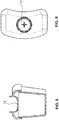
- eine Ansicht des Deckels gemäss
Figur 4 von oben; - Figur 7
- einen Längsschnitt durch eine erfindungsgemässe Abpumpeinheit in einer zweiten Ausführungsform;
- Figur 8
- eine perspektivische Ansicht eines Milchsammelbehälters zur Verwendung in der Abpumpeinheit gemäss
Figur 1 ; - Figur 9
- einen Längsschnitt durch eine erfindungsgemässe Abpumpeinheit in einer dritten Ausführungsform;
- Figur 10
- einen Längsschnitt durch eine nicht beanspruchte weiteren Abpumpeinheit in einer vierten Ausführungsform;
- Figur 11
- eine perspektivische Darstellung der Abpumpeinheit gemäss
Figur 10 in einer ersten Position; - Figur 12
- eine Seitenansicht der Abpumpeinheit gemäss
Figur 10 in einer zweiten Position; - Figur 13
- eine Seitenansicht durch eine nicht beanspruchte weitere Abpumpeinheit in einer fünften Ausführungsform in einer ersten Position;
- Figur 14
- eine Seitenansicht der Abpumpeinheit gemäss
Figur 13 in einer zweiten Position; - Figur 15
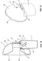
- einen Teilschnitt in einer Seitenansicht einer erweiterten nicht beanspruchten Ausfuhrungsform gemäss
Figur 13 und - Figur 16
- einen Längsschnitt durch eine erfindungsgemässe Abpumpeinheit in einer sechsten Ausführungsform.
- In den
Figuren 1 bis 3 ist ein erstes Ausführungsbeispiel der erfindungsgemässen Abpumpeinheit dargestellt. Sie umfasst einen Milchsammelbehälter 1, 2 und eine Brusthaube 3. Die Brusthaube 3 weist eine erste Längsmittelachse a auf, der Milchsammelbehälter eine zweite Längsmittelachse b. Diese Achsen a, b stehen in einem Winkel zueinander.
Der Milchsammelbehälter 1 weist einen Behälterteil 1 mit einem Innenraum zur Aufnahme der abgepumpten Milch und einen diesen Behälterteil 1 verschliessenden Deckel 2 auf. Mindestens der Behälterteil 1, vorzugsweise auch der Deckel 2, ist formstabil oder annähernd formstabil ausgebildet. Vorzugsweise sind sie relativ steif ausgebildet. Sie bestehen üblicherweise aus einem Kunststoff. Der Deckel 2 lässt sich in einer einfachen Ausfuhrungsform lösbar auf den Behälterteil 1 aufstecken. Der Behälterteil 1 weist hierfür eine oder mehrere Rückhalterippen 10 auf, welche seinen oberen Umfang umlaufen und in den Deckel 2, vorzugsweise in eine entsprechende umlaufende Nut, eingreifen. Ist der Behälter rund ausgebildet, so lässt sich alternativ auch ein Drehverschluss verwenden. Klemmen oder andere Befestigungsmittel sind ebenfalls möglich.
Der Behälterteil 1 ist vorzugsweise selbststehend ausgebildet. Er weist hierfür einen stabilen Bodenbereich oder vorstehende Fussnoppen auf.
Der Deckel 2 weist einen Deckelkörper 20 mit einer nach oben gerichteten Oberfläche auf. In dieser Oberfläche ist eine Gelenkkugelaufnahme 21 vorhanden. Die Gelenkkugelaufnahme 21 ist teilkugelförmig ausgebildet, wobei federnde Klammern 210 eine runde Öffnung umgeben. Diese runde Öffnung führt in den Innenraum des Behälterteils 1. - Die Brusthaube 3 ist ebenfalls vorzugsweise aus Kunststoff gefertigt. Sie weist einen sich nach aussen erweiternden Trichter 32 zur Aufnahme der Mutterbrust auf. Der Trichter 32 endet in einem röhrenförmigen Abschnitt 39 mit einem Vakuumanschluss 33 zur Verbindung mit einer Vakuumpumpe bzw. mit einem zur Vakuumpumpe führenden Schlauch. Trichter 32 und röhrenförmiger Abschnitt 39 sind beide relativ klein gehalten. Anstelle der dargestellten klassischen Trichterform lassen sich auch andere Formen von Brusthauben einsetzen. Dies gilt auch für die übrigen in diesem Text beschriebenen Ausführungsbeispiele. Die Brusthaube 3 ist vorzugsweise, wie hier dargestellt, einstückig ausgebildet. Sie kann jedoch auch mehrstückig ausgebildet sein. Die Brusthaube 3 ist vorzugsweise aus einem steifen oder annähernd steifen Material gefertigt. Sie kann jedoch, insbesondere im Bereich des Trichters 32, auch aus einem relativ weichen, sich der Mutterbrust in der Form anpassenden Material gefertigt sein. Mindestens der röhrenförmige Teil 39 ist jedoch vorzugsweise steif oder zumindest formstabil ausgebildet. Auch diese Varianten sind für die übrigen Ausführungsbeispiele möglich.
- Der untere Bereich des röhrenförmigen Abschnitts 39 der Brusthaube 3 geht in einen steifen Hals 30 über, an welchem eine Gelenkkugel 31 angeformt ist. Diese Gelenkkugel 31 ist lösbar in der Gelenkkugelaufnahme 21 gehalten. Sie lässt sich innerhalb der Aufnahme drehen, wobei das Gelenk vorzugsweise selbsthemmend ausgebildet ist, so dass die Kugel 31 und somit die Brusthaube 3 ohne weitere Fixierungsmittel in einer von der Mutter gewählten Position relativ zum Behälter 1, 2 verbleibt. Diese Hemmung erfolgt vorzugsweise mittels der federnden Klammern 210.
- Ein Verbindungskanal 34 verläuft durch den Hals 30 und die Gelenkkugel 31 und verbindet den Innenraum 390 der Brusthaube 3 mit dem Innenraum 11 des Behälterteils 1. Im Verbindungskanal 34 ist ein Rückschlagventil, hier ein Entenschnabelventil 4 angeordnet. Es liegt in diesem Beispiel auf einem Absatz des Verbindungskanals 34 auf. Dieser Absatz ist am oberen Ende des Verbindungskanals 34 ausgebildet, d.h. beim Übergang zum röhrenförmigen Abschnitt 39. Dadurch lässt sich das Ventil 4 über den Trichter 32 der Brusthaube 3 an diese Position einführen.
- In den
Figuren 4 bis 6 ist eine erweiterte Ausführungsform des oben beschriebenen Beispiels dargestellt. Der Deckelkörper 2 ist in dieser Ausfuhrungsform mit einem reversiblen Verschluss 13 ausgestattet. Dieser Verschluss 13 öffnet sich beim Einsetzen der Gelenkkugel 31. Der Verschluss 13 kann als federnde Segmente, z.B. wie hier dargestellt als Kreuzschlitzmembran, ausgebildet sein. Somit kann der Behälter zu Lagerungszwecken mindestens annähernd dicht aufbewahrt werden, ohne dass ein zusätzlicher Deckel notwendig ist. - In der Ausfuhrungsform gemäss
Figur 7 ist das Ventil 4 in einem Einschubelement 5 gehalten, welches sich von unten, d.h. vom anderen freien Ende des Verbindungskanals 34 einführen lässt. Der Kanal 34 ist entsprechend mit einem Anschlag versehen, auf welchem eine umlaufende Schulter des Einschubelements 5 anliegt. Das Einschubelement 5 ist vorzugsweise ebenfalls aus Kunststoff gefertigt. Das Ventil 4 kann, wie hier dargestellt, als separates Teil ausgebildet sein oder einstückig mit dem Einschubelement 5 ausgebildet sein. -
Figur 8 zeigt eine bevorzugte Form eines Milchsammelbehälters 1, 2, welcher sich in der erfindungsgemässen Abpumpeinheit verwenden lässt. Der Behälterteil 1 weist vorzugsweise einen nierenförmigen Querschnitt auf, so dass er eine nach innen gebogene Wand und eine gegenüberliegende nach aussen gebogene Wand aufweist. Der Deckel 2 ist analog ausgebildet. Die nach innen gebogene Wand lässt sich an den Körper der Mutter, z.B. an die Mutterbrust anlegen, so dass der Behälter sehr nahe an den Körper gebracht werden kann. Dieser Behälter lässt sich in allen hier beschriebenen Ausführungsformen der erfindungsgemässen Abpumpeinheit verwenden. Er lässt sich auch in anderen Abpumpeinheiten einsetzen, um eine möglichst platzsparende Anordnung an der Brust zu ermöglichen. Vorteilhaft ist ferner, dass sich mehrere Behälterteile 1 sowohl in vertikaler Richtung ineinander stapeln lässt wie auch in horizontaler Richtung ohne Zwischenräume nebeneinander anordnen lassen. Dadurch lassen sie sich äusserst platzsparend lagern. - In der Ausführungsform gemäss
Figur 9 ist ein Adapterteil 6 zwischen Brusthaube 3 und Milchsammelbehälter 1, 2 angeordnet. Die Brusthaube 3 ist auf dem Adapterteil 6 aufgesteckt. Sie kann lösbar mit ihm verbunden sein, damit die einzelnen Teile getrennt voneinander gereinigt und wieder zusammengesetzt werden können. Sie kann jedoch auch nicht zerstörungsfrei fest mit ihm verbunden sein. Dies ist insbesondere bei Brusthauben 3, welche für den Einmalgebrauch oder für einen kurzzeitigen Mehrfachgebrauch bestimmt sind, vorteilhaft.
Das Adapterteil 6 bildet den Hals der Brusthaube 3 und weist an seinem freien Ende die Gelenkkugel auf. Eine Durchgangsöffnung bildet den Verbindungskanal 34. Auch diese Ausfiihrungsform weist vorzugsweise ein Rückschlagventil 4 auf. Dieses ist hier wiederum am oberen Ende angeordnet. Es kann jedoch auch mit dem Einschubelement 5 gemässFigur 7 oder einer anderen Ventilanordnung versehen sein. - In den
Figuren 10 bis 12 ist ein nicht beanspruchtes weiteres Ausführungsbeispiel dargestellt. In den bisherigen Beispielen wurde die Milch durch das Gelenk geleitet. In diesem Beispiel ist das Gelenk getrennt vom Verbindungskanal 34 angeordnet. Das Gelenk ist durch ein Scharniergelenk gebildet. An der Brusthaube 3 ist ein Scharnierstift 38 befestigt, vorzugsweise einstückig angeformt, welcher in einem Scharnierträger 22 schwenkbar gehalten ist. Der Scharnierträger 22 ist wiederum auf dem Deckel 2 des Milchsammelbehälters befestigt, vorzugsweise ebenfalls einstückig mit diesem ausgebildet. Der Deckel 2 ist vorzugsweise, wie in diesem Beispiel dargestellt, plan ausgebildet. Er weist beabstandet zum Scharnier eine Durchlassöffnung 12 auf, durch welche eine Milchleitung 8 ragt. Die Milchleitung 8 ist fest mit der Brusthaube 3 verbunden. Sie bildet den Durchgangskanal 34. Die Milchleitung 8 ist vorzugsweise ein steifer oder flexibler Schlauch. Auch hier ist vorzugsweise wiederum ein Rückschlagventil 4 vorhanden. Es kann beispielsweise am Anfang oder wie hier dargestellt am Ende der Milchleitung 8 an dieser befestigt sein.
Es lässt sich auch hier dieselbe Brusthaube 3 verwenden wie im ersten Beispiel. Die dargestellte Variante ist jedoch in dieser Kombination äusserst platzsparend und kompakt. Sie weist eine halbkreisförmige, vorzugsweise steife Brusthaubenschale 35 auf, in welcher ein Trichtereinsatz 36 gehalten ist. Er weist einen umlaufenden Rand auf, welcher über den umlaufenden Rand der Brusthaubenschale 35 gestülpt ist. Das schmale Ende des Trichtereinsatzes 36 ist in einer vorzugsweise steifen Trichteraufnahme 37 gehalten. Diese Trichteraufnahme 37 ist in der Brusthaubenschale 35 befestigt, wobei sie einen Stutzen aufweist, welcher die Brusthaubenschale 35 nach aussen durchdringt und den Vakuumanschluss 33 bildet. Vorzugsweise ist, wie hier dargestellt, die Milchleitung 8 einstückig mit der Trichteraufnahme 37 ausgebildet oder an ihr befestigt.
Wie in der Zusammenschau derFiguren 10 und12 erkennbar ist, lässt sich nun die Brusthaube 3 relativ zum Behälter 1, 2 um eine Schwenkachse schwenken. Die Durchlassöffnung 12 ist dabei so gross bemessen, dass die Milchleitung 8 darin genügend Spielraum hat, um die Bewegung mitzumachen, ohne geknickt zu werden. Es ist nicht notwendig, dass der Behälter 1, 2 in diesem Bereich vollständig verschlossen ist. - In den
Figuren 14 und16 ist eine nicht beanspruchte weitere Ausfuhrungsform dargestellt. Hier ist das Gelenk durch einen flexiblen Stutzen 7 gebildet. Der Stutzen 7 weist vorzugsweise Längen im Bereich von 20 bis 50 mm auf. Der Stutzen ist vorzugsweise durch einen Schlauch, vorzugsweise einen Breitbandschlauch, d.h. einem flachen Schlauch gebildet. Vorzugsweise weist er auf seiner Innenseite Strukturen, wie beispielsweise Längsrippen auf, damit er nicht knickt und/oder sich der Querschnitt nicht verschliessen kann. Er ist vorzugsweise steif genug ausgebildet, um eine eingestellte Position selbsttätig zu halten, so dass der Behälter 1,2 die Brusthaube 3 innerhalb einer bestimmten Bandbreite von Schwenkwinkeln in unterschiedlichen Schwenkwinkeln und ohne äusseren Kraftaufwand tragen kann. - In einer nicht beanspruchten Ausführungsform, welche in
Figur 15 dargestellt ist, weist der Schlauch bzw. Stutzen 7 Verstärkungselemente auf. Vorzugsweise sind dies ein oder mehrere Drähte 70, welche in oder an der Wandung des Stutzens 7 angeordnet sind.
Der Stutzen 7 ist einerseits an der Brusthaube 3 und andererseits am Deckel 2 des Milchsammelbehälters befestigt. Er kann auf beiden Seiten lösbar befestigt sein oder an einer oder beiden Seiten fest und nicht zerstörungsfrei lösbar mit diesen Teilen verbunden sein. Vorzugsweise ist er eingesteckt und weist entsprechende Rückhalterippen und/odernuten auf. Der Stutzen 7 ermöglicht vorzugsweise eine Schwenkung in einer Hauptrichtung unter einer leichten Neigung in anderen Richtungen.
Auch in diesem Beispiel ist vorzugsweise ein Rückschlagventil 4 vorhanden. Hier ist es wiederum in der Brusthaube 3 angeordnet. - In der Ausfuhrungsform gemäss
Figur 16 ist das Gelenk wiederum ein Kugelgelenk. Hier ist jedoch am Deckel 2 des Milchsammelbehälters eine Gelenkkugel 23 angeordnet, insbesondere einstückig mit ihm gefertigt. Die Brusthaube 3 weist eine entsprechende Gelenkkugelaufnahme auf. Der Verbindungskanal 34 der Brusthaube 3 geht in einen Verbindungskanal 24 in der Gelenkkugel 23 über. Damit diese Verbindung auch bei relativ grossen Schwenkwinkeln offen bleibt, ist das obere Ende des deckelseitigen Verbindungskanals 24 mit einem sich erweiternden Einlasstrichter 25 versehen. - Die erfindungsgemässe Abpumpeinheit lässt sich kompakt und platzsparend ausbilden und eignet sich insbesondere in einer "hands-free" Anordnung.
BEZUGSZEICHENLISTE 1 Behälterteil 35 Brusthaubenschale 10 Rückhalterippe 36 Trichtereinsatz 11 Innenraum 37 Trichteraufnahme 12 Durchlassöffnung 38 Scharnierstift 13 Verschluss 39 röhrenförmiger Abschnitt 390 Innenraum 2 Deckel 20 Deckelkörper 4 Ventil 21 Kugelaufnahme 210 Klammer 5 Einschubelement 22 Scharnierträger 23 Gelenkkugel 6 Adapterteil 24 Verbindungskanal 25 Einlasstrichter 7 Stutzen 70 Draht 3 Brusthaube 30 Hals 8 Milchleitung 31 Gelenkkugel 32 Trichter a erste Längsmittelachse 33 Vakuumanschluss b zweite Längsmittelachse 34 Verbindungskanal
Claims (8)
- Abpumpeinheit zur Verwendung in einer Vorrichtung zum Abpumpen von menschlicher Muttermilch, wobei die Abpumpeinheit eine Brusthaube (3) zur Anlage an eine Mutterbrust und einen formstabilen oder annähernd formstabilen Milchsammelbehälter (1, 2) zur Aufnahme der abgepumpten Muttermilch aufweist, wobei die Brusthaube (3) eine erste Längsmittelachse (a) und der Milchsammelbehälter (1, 2) eine zweite Längsmittelachse (b) aufweist, wobei der Milchsammelbehälter (1, 2) lösbar an der Brusthaube (3) befestigbar ist und wobei die erste Längsmittelachse (a) im befestigten Zustand des Milchsammelbehälters (1, 2) in einem Winkel zur zweiten Längsmittelachse (b) angeordnet ist, wobei der Milchsammelbehälter (1, 2) im befestigten Zustand relativ zur Brusthaube (3) bewegbar ist, wodurch der Winkel zwischen der ersten Längsmittelachse (a) und zweiten Längsmittelachse (b) veränderbar ist, wobei ein erstes und ein zweites Kopplungsteil (31, 21; 23) vorhanden sind, welche gemeinsam die Relativbewegung ermöglichen, wobei das erste Kopplungsteil (31) an der Brusthaube (3) und das zweite Kopplungsteil (21, 23) am Milchsammelbehälter (1, 2) angeordnet ist, wobei das erste Kopplungsteil (31) mit dem zweiten Kopplungsteil (21, 23) ein Kugelgelenk bildet, welches den Milchsammelbehälter (1, 2) mit der Brusthaube (3) verbindet, wobei im Kugelgelenk ein Verbindungskanal (24, 34) vorhanden ist, welcher einen Innenraum (390) der Brusthaube (3) mit einem Innenraum (11) des Milchsammelbehälters (1) verbindet, um Milch von der Brusthaube (3) in den Milchsammelbehälter (1, 2) zu leiten, dadurch gekennzeichnet, dass eine Position der Brusthaube (3) existiert, in welcher sich dieser Verbindungskanal (24, 34) in Richtung der zweiten Längsmittelachse (b) erstreckt, und dass entwedera) das Kugelgelenk eine Gelenkkugel (31) aufweist, welche an der Brusthaube (3) angeformt oder angeordnet ist, wobei das Kugelgelenk eine Kugelaufnahme (21) aufweist, welche in einem Deckel (2) des Milchsammelbehälters (1, 2) angeformt oder angeordnet ist, oder dassb) das Kugelgelenk eine Gelenkkugel (23) aufweist, welche an einem Deckel (2) des Milchsammelbehälters (1, 2) angeformt oder angeordnet ist.
- Abpumpeinheit nach Anspruch 1, wobei der Milchsammelbehälter ein Behälterteil (1) und den diesen Behälterteil (1) verschliessenden Deckel (2) aufweist.
- Abpumpeinheit nach einem der Ansprüche 1 oder 2, wobei das erste Kopplungsteil (31) einstückig an einem Teil der Brusthaube (3) und/oder das zweite Kopplungsteil (21, 23) einstückig an einem Teil des Milchsammelbehälters (1, 2) angeformt ist.
- Abpumpeinheit nach einem der Ansprüche 1 oder 2, wobei mindestens eines der zwei Kopplungsteile (6) ein zum Milchsammelbehälter (1, 2) und Brusthaube (3) zusätzliches Teil ist, wobei das zusätzliche Kopplungsteil (6) in Richtung der Verbindung zwischen Milchsammelbehälter (1, 2) und Brusthaube (3) eine Länge aufweist, welche wesentlich kleiner als die Höhe des Milchsammelbehälters (1, 2) und/oder der Brusthaube (3) ist.
- Abpumpeinheit nach einem der Ansprüche 1 bis 4, wobei der Milchsammelbehälter (1,2) einen nierenförmigen Querschnitt aufweist.
- Brusthaube (3) einer Abpumpeinheit nach einem der Ansprüche 1 bis 5, wobei die Brusthaube (3) eine erste Längsmittelachse (a) definiert und ein erstes Kopplungsteil (31) aufweist, welches eine Relativbewegung zwischen der Brusthaube (3) und einem Milchsammelbehälter (1, 2) ermöglicht in einem Zustand, in welchem der Milchsammelbehälter (1, 2) an der Brusthaube (3) befestigt ist, wobei der Milchsammelbehälter (1, 2) eine zweite Längsmittelachse (b) definiert, wobei das erste Kopplungsteil (31) mit einem zweiten Kopplungsteil (21, 23) des Milchsammelbehälters (1, 2) verbindbar ist, wobei die zwei Kopplungsteile gemeinsam die Relativbewegung ermöglichen, wobei der Winkel zwischen der ersten Längsmittelachse (a) und der zweiten Längsmittelachse (b) im befestigen Zustand des Milchsammelbehälters (1, 2) veränderbar ist, , wobei das erste Kopplungsteil (31) mit dem zweiten Kopplungsteil (21, 23) ein Kugelgelenk bildet, wobei im Kugelgelenk ein Verbindungskanal (24, 34) vorhanden ist, welcher einen Innenraum (390) der Brusthaube (3) mit einem Innenraum (11) des Milchsammelbehälters (1) verbindet, um Milch von der Brusthaube (3) in den Milchsammelbehälter (1, 2) zu leiten, wobei das erste Kopplungsteil eine Gelenkkugel (31) oder eine Kugelaufnahme (21) des Kugelgelenks aufweist und das zweite Kopplungsteil (21, 23) eine entsprechende Kugelaufnahme (21) oder eine Gelenkkugel (31) des Kugelgelenks aufweist und wobei eine Position der Brusthaube (3) existiert, in welcher sich dieser Verbindungskanal (24, 34) in Richtung der zweiten Längsmittelachse (b) erstreckt, dadurch gekennzeichnet, dass eine Position der Brusthaube (3) existiert, in welcher sich der Verbindungskanal (24, 34) in eine Richtung erstreckt, die mit der ersten Längsmittelachse (a) einen Winkel bildet.
- Milchsammelbehälter (1, 2) zur Verwendung in einer Abpumpeinheit nach einem der Ansprüche 1 bis 5, wobei der Milchsammelbehälter (1, 2) formstabil oder annähernd formstabil ausgebildet ist und wobei er ein zweites Kopplungsteil (21, 23) aufweist, welches eine Relativbewegung zwischen dem Milchsammelbehälter (1, 2) und einer Brusthaube (3) ermöglicht in einem Zustand, in welchem der Milchsammelbehälter (1, 2) an der Brusthaube (3) befestigt ist, wobei der Milchsammelbehälter (1, 2) eine zweite Längsmittelachse (b) definiert, wobei das zweite Kopplungsteil (21, 23) mit einem ersten Kopplungsteil (31) der Brusthaube (3) verbindbar ist, wobei die zwei Kopplungsteile gemeinsam die Relativbewegung ermöglichen, wobei der Winkel zwischen der ersten Längsmittelachse (a) und der zweiten Längsmittelachse (b) im befestigen Zustand des Milchsammelbehälters (1, 2) veränderbar ist, wobei das erste Kopplungsteil (31) mit dem zweiten Kopplungsteil (21, 23) ein Kugelgelenk bildet, wobei im Kugelgelenk ein Verbindungskanal (24, 34) vorhanden ist, welcher einen Innenraum (390) der Brusthaube (3) mit einem Innenraum (11) des Milchsammelbehälters (1) verbindet, um Milch von der Brusthaube (3) in den Milchsammelbehälter (1, 2) zu leiten, wobei das erste Kopplungsteil eine Gelenkkugel (31) oder eine Kugelaufnahme (21) des Kugelgelenks aufweist und das zweite Kopplungsteil (21, 23) eine entsprechende Kugelaufnahme (21) oder eine Gelenkkugel (31) des Kugelgelenks aufweist und wobei eine Position der Brusthaube (3) existiert, in welcher sich der Verbindungskanal (24, 34) in Richtung der zweiten Längsmittelachse (b) erstreckt.
- Kopplungseinheit (31, 21; 23) zur Verwendung in einer Abpumpeinheit gemäss einem der Ansprüche 1 bis 5, wobei die Kopplungseinheit (31, 21; 23) ein erstes und ein zweites Kopplungsteil aufweist zur Verbindung einer Brusthaube (3) mit einer ersten Längsmittelachse (a) und einem formstabilen oder annähernd formstabilen Milchsammelbehälter (1, 2) mit einer zweiten Längsmittelachse (b), wobei das erste und das zweite Kopplungsteil gemeinsam eine Relativbewegung zwischen der Brusthaube (3) und dem an der Brusthaube (3) befestigten Milchsammelbehälter (1, 2) ermöglichen, , wobei der Winkel zwischen der ersten Längsmittelachse (a) und der zweiten Längsmittelachse (b) im befestigen Zustand des Milchsammelbehälters (1, 2) an der Brusthaube (3) veränderbar ist, wobei das erste Kopplungsteil (31) mit dem zweiten Kopplungsteil (21, 23) ein Kugelgelenk bildet, wobei im Kugelgelenk ein Verbindungskanal (24, 34) vorhanden ist, welcher einen Innenraum (390) der Brusthaube (3) mit einem Innenraum (11) des Milchsammelbehälters (1) verbindet, um Milch von der Brusthaube (3) in den Milchsammelbehälter (1, 2) zu leiten und wobei das erste Kopplungsteil eine Gelenkkugel (31) oder eine Kugelaufnahme (21) des Kugelgelenks aufweist und das zweite Kopplungsteil (21, 23) eine entsprechende Kugelaufnahme (21) oder eine Gelenkkugel (31) des Kugelgelenks aufweist und wobei eine Position der Brusthaube (3) existiert, in welcher sich dieser Verbindungskanal (24, 34) in Richtung der zweiten Längsmittelachse (b) erstreckt.
Applications Claiming Priority (3)
| Application Number | Priority Date | Filing Date | Title |
|---|---|---|---|
| US201261722563P | 2012-11-05 | 2012-11-05 | |
| US13/828,333 US9205185B2 (en) | 2012-11-05 | 2013-03-14 | Pump unit for expressing milk |
| PCT/EP2013/072827 WO2014068066A1 (de) | 2012-11-05 | 2013-10-31 | Abpumpeinheit zum abpumpen von muttermilch |
Publications (2)
| Publication Number | Publication Date |
|---|---|
| EP2914313A1 EP2914313A1 (de) | 2015-09-09 |
| EP2914313B1 true EP2914313B1 (de) | 2018-01-03 |
Family
ID=50623014
Family Applications (1)
| Application Number | Title | Priority Date | Filing Date |
|---|---|---|---|
| EP13789745.0A Not-in-force EP2914313B1 (de) | 2012-11-05 | 2013-10-31 | Abpumpeinheit zum abpumpen von muttermilch |
Country Status (5)
| Country | Link |
|---|---|
| US (1) | US9205185B2 (de) |
| EP (1) | EP2914313B1 (de) |
| CN (1) | CN104812422B (de) |
| TW (1) | TWI597077B (de) |
| WO (1) | WO2014068066A1 (de) |
Families Citing this family (14)
| Publication number | Priority date | Publication date | Assignee | Title |
|---|---|---|---|---|
| CH708400A1 (de) * | 2013-07-16 | 2015-01-30 | Medela Holding Ag | Brustpumpeneinheit. |
| US20160000980A1 (en) * | 2014-03-20 | 2016-01-07 | Naya Health, Inc. | Pump apparatus and methods for expression of human breast milk |
| WO2016007561A1 (en) | 2014-07-07 | 2016-01-14 | Naya Health, Inc. | Methods and apparatus for transferring pressure during expression of human breast milk |
| EP3590420A1 (de) * | 2014-09-16 | 2020-01-08 | ExploraMed NC7, Inc. | Systeme, vorrichtungen und verfahren zur beurteilung des aus einer brust exprimierten milchvolumens |
| EP3058967A1 (de) | 2015-02-20 | 2016-08-24 | Medela Holding AG | Brusthaubeneinheit und Konnektor für eine Brustpumpe |
| CN104784766B (zh) * | 2015-05-05 | 2018-04-17 | 陈俊波 | 一种三通部件及带有这种三通部件的吸奶器 |
| CN105905409A (zh) * | 2016-03-29 | 2016-08-31 | 南京明基医院有限公司 | 接奶袋 |
| TWI675675B (zh) * | 2017-11-27 | 2019-11-01 | 黃士哲 | 隱形擠乳裝置 |
| EP3536359A1 (de) * | 2018-03-06 | 2019-09-11 | Medela Holding AG | Brusthaubeneinheit |
| CN109453457B (zh) * | 2018-12-21 | 2021-08-13 | 天津市第四中心医院 | 一种耳鼻喉临床护理喷药装置 |
| US11523688B2 (en) * | 2020-04-17 | 2022-12-13 | Restful Pump, Inc. | Adjustable breast pump flange |
| US11779688B2 (en) * | 2021-01-21 | 2023-10-10 | Wayne D Turner | Breast shield |
| US11759554B1 (en) * | 2021-01-21 | 2023-09-19 | Wayne D Turner | Breast shield with suckling motion one-way valve |
| US12521472B2 (en) * | 2022-08-17 | 2026-01-13 | Wayne D. Turner | Breast shield with suckling motion one way valve |
Family Cites Families (18)
| Publication number | Priority date | Publication date | Assignee | Title |
|---|---|---|---|---|
| US4680028A (en) | 1984-07-02 | 1987-07-14 | Lact-Assist, Incorporated | Flexible breast receptor for breast pump |
| US5571084A (en) | 1994-12-12 | 1996-11-05 | Spread Spectrum Inc. | Microprocessor-controlled vested lactation system |
| EP1034807A1 (de) | 1998-03-06 | 2000-09-13 | Ameda AG | Saugglocke für eine Brustpumpe |
| WO1999044650A1 (en) * | 1998-03-06 | 1999-09-10 | Ameda Ag Medical Equipment | Breast pump |
| US6073788A (en) | 1998-10-26 | 2000-06-13 | Evenflo Company, Inc. | Tactile baby bottle |
| US6092680A (en) | 1998-11-30 | 2000-07-25 | Pillado; Rodolfo Mario | Baby bottle assembly |
| USD420448S (en) * | 1999-01-15 | 2000-02-08 | Handi-Craft Company | Nursing bottle with indented sides and vent tube |
| JP2001087377A (ja) * | 1999-09-20 | 2001-04-03 | Hirose Electric Co Ltd | 脈動式搾乳器 |
| AU2002316283B2 (en) | 2001-06-19 | 2008-01-24 | Medela Holding Ag | System for a portable hands-free breast pump and method of using the same |
| GB0119074D0 (en) * | 2001-08-06 | 2001-09-26 | Handley Kuester Ltd | Breast pumps |
| US6749582B2 (en) * | 2002-04-30 | 2004-06-15 | The First Years Inc. | Pumping breast milk |
| US20040087898A1 (en) | 2002-11-01 | 2004-05-06 | Gotthilf Weniger | Breast pump assembly |
| US8152754B2 (en) * | 2004-04-01 | 2012-04-10 | Medela Holding Ag | Soft breastshield |
| US7559915B2 (en) | 2004-10-13 | 2009-07-14 | Stella Dao | Breast pump device with self-contained breast milk reservoir |
| AT503143B1 (de) | 2006-01-24 | 2008-04-15 | Mam Babyartikel | Milchpumpe sowie aufsatzteil hiefür |
| US8187227B2 (en) | 2006-11-01 | 2012-05-29 | Medela Holding Ag | Self returning contamination barrier |
| US7824363B2 (en) | 2007-05-04 | 2010-11-02 | Medela Holding Ag | Hands-free breast pump with balanced reciprocating drive |
| CN201370807Y (zh) * | 2008-12-31 | 2009-12-30 | 张强 | 自由旋转实用型吸奶器 |
-
2013
- 2013-03-14 US US13/828,333 patent/US9205185B2/en active Active
- 2013-10-31 WO PCT/EP2013/072827 patent/WO2014068066A1/de not_active Ceased
- 2013-10-31 EP EP13789745.0A patent/EP2914313B1/de not_active Not-in-force
- 2013-10-31 CN CN201380057826.5A patent/CN104812422B/zh not_active Expired - Fee Related
- 2013-11-05 TW TW102140020A patent/TWI597077B/zh active
Also Published As
| Publication number | Publication date |
|---|---|
| US20140128806A1 (en) | 2014-05-08 |
| WO2014068066A1 (de) | 2014-05-08 |
| EP2914313A1 (de) | 2015-09-09 |
| CN104812422A (zh) | 2015-07-29 |
| US9205185B2 (en) | 2015-12-08 |
| TWI597077B (zh) | 2017-09-01 |
| CN104812422B (zh) | 2017-06-23 |
| TW201434502A (zh) | 2014-09-16 |
Similar Documents
| Publication | Publication Date | Title |
|---|---|---|
| EP2914313B1 (de) | Abpumpeinheit zum abpumpen von muttermilch | |
| EP2934616B1 (de) | Brusthaubeneinheit | |
| EP2911715B1 (de) | Brusthaube mit medientrennung | |
| EP2934615B1 (de) | Brusthaubeneinheit mit medientrennung | |
| EP0374637B1 (de) | Vorrichtung zum Zubereiten von Cappuccino | |
| EP3258984B1 (de) | Brusthaube | |
| EP3258981B1 (de) | Adapter mit medientrennmembran für eine brusthaube | |
| EP4104876A1 (de) | Brusthaube mit flexiblem rand | |
| DE3023583A1 (de) | Tauchrohr und ventil mit schnelltrennkupplung fuer einen zusammenlegbaren behaelter | |
| DE102004030692B3 (de) | Milchabsaugvorrichtung | |
| WO2011035448A1 (de) | Brusthaube zum abpumpen von menschlicher muttermilch | |
| EP2589322A1 (de) | Kaffeemaschine, insbesondere Espressovollautomat | |
| EP3045091B1 (de) | Getränkezubereitungsvorrichtung sowie betriebsverfahren | |
| EP3058967A1 (de) | Brusthaubeneinheit und Konnektor für eine Brustpumpe | |
| EP3045092B1 (de) | Getränkezubereitungsvorrichtung sowie betriebsverfahren | |
| DE102012111429A1 (de) | Kartuschenhalterung einer Dialysemaschine mit integrierter Positionierhilfe | |
| EP2523585B1 (de) | Vorrichtung nach dem steigrohrprinzip für die zubereitung eines heissgetränks, insbesondere espressokanne | |
| EP2710940A1 (de) | Mehrwegeventil | |
| EP2380472A1 (de) | Kaffeemaschine | |
| EP0641726A1 (de) | Vorrichtung zum Bereithalten und Abgeben von heissen oder kalten Getränken | |
| EP2721976A1 (de) | Zerlegbarer Zentralauslauf eines Getränkebereiters | |
| EP2987434B1 (de) | Milcherwärmungs- und/oder milchaufschäumvorrichtung sowie getränkezubereitungsvorrichtung | |
| WO2009129770A1 (de) | Probe-entnahmeventil | |
| DE29820526U1 (de) | Urinmeßgerät | |
| DE102016215633B4 (de) | Melkbecherhülse und modulares Melkbecherhülsensystem |
Legal Events
| Date | Code | Title | Description |
|---|---|---|---|
| PUAI | Public reference made under article 153(3) epc to a published international application that has entered the european phase |
Free format text: ORIGINAL CODE: 0009012 |
|
| 17P | Request for examination filed |
Effective date: 20150423 |
|
| AK | Designated contracting states |
Kind code of ref document: A1 Designated state(s): AL AT BE BG CH CY CZ DE DK EE ES FI FR GB GR HR HU IE IS IT LI LT LU LV MC MK MT NL NO PL PT RO RS SE SI SK SM TR |
|
| AX | Request for extension of the european patent |
Extension state: BA ME |
|
| DAX | Request for extension of the european patent (deleted) | ||
| 17Q | First examination report despatched |
Effective date: 20160226 |
|
| GRAP | Despatch of communication of intention to grant a patent |
Free format text: ORIGINAL CODE: EPIDOSNIGR1 |
|
| STAA | Information on the status of an ep patent application or granted ep patent |
Free format text: STATUS: GRANT OF PATENT IS INTENDED |
|
| INTG | Intention to grant announced |
Effective date: 20170705 |
|
| GRAS | Grant fee paid |
Free format text: ORIGINAL CODE: EPIDOSNIGR3 |
|
| GRAJ | Information related to disapproval of communication of intention to grant by the applicant or resumption of examination proceedings by the epo deleted |
Free format text: ORIGINAL CODE: EPIDOSDIGR1 |
|
| GRAL | Information related to payment of fee for publishing/printing deleted |
Free format text: ORIGINAL CODE: EPIDOSDIGR3 |
|
| STAA | Information on the status of an ep patent application or granted ep patent |
Free format text: STATUS: EXAMINATION IS IN PROGRESS |
|
| GRAR | Information related to intention to grant a patent recorded |
Free format text: ORIGINAL CODE: EPIDOSNIGR71 |
|
| STAA | Information on the status of an ep patent application or granted ep patent |
Free format text: STATUS: GRANT OF PATENT IS INTENDED |
|
| GRAA | (expected) grant |
Free format text: ORIGINAL CODE: 0009210 |
|
| STAA | Information on the status of an ep patent application or granted ep patent |
Free format text: STATUS: THE PATENT HAS BEEN GRANTED |
|
| INTC | Intention to grant announced (deleted) | ||
| AK | Designated contracting states |
Kind code of ref document: B1 Designated state(s): AL AT BE BG CH CY CZ DE DK EE ES FI FR GB GR HR HU IE IS IT LI LT LU LV MC MK MT NL NO PL PT RO RS SE SI SK SM TR |
|
| INTG | Intention to grant announced |
Effective date: 20171127 |
|
| REG | Reference to a national code |
Ref country code: GB Ref legal event code: FG4D Free format text: NOT ENGLISH |
|
| REG | Reference to a national code |
Ref country code: CH Ref legal event code: EP Ref country code: AT Ref legal event code: REF Ref document number: 959646 Country of ref document: AT Kind code of ref document: T Effective date: 20180115 |
|
| REG | Reference to a national code |
Ref country code: IE Ref legal event code: FG4D Free format text: LANGUAGE OF EP DOCUMENT: GERMAN |
|
| REG | Reference to a national code |
Ref country code: CH Ref legal event code: NV Representative=s name: ISLER AND PEDRAZZINI AG, CH |
|
| REG | Reference to a national code |
Ref country code: DE Ref legal event code: R096 Ref document number: 502013009198 Country of ref document: DE |
|
| REG | Reference to a national code |
Ref country code: NL Ref legal event code: MP Effective date: 20180103 |
|
| REG | Reference to a national code |
Ref country code: LT Ref legal event code: MG4D |
|
| PG25 | Lapsed in a contracting state [announced via postgrant information from national office to epo] |
Ref country code: NL Free format text: LAPSE BECAUSE OF FAILURE TO SUBMIT A TRANSLATION OF THE DESCRIPTION OR TO PAY THE FEE WITHIN THE PRESCRIBED TIME-LIMIT Effective date: 20180103 |
|
| PG25 | Lapsed in a contracting state [announced via postgrant information from national office to epo] |
Ref country code: CY Free format text: LAPSE BECAUSE OF FAILURE TO SUBMIT A TRANSLATION OF THE DESCRIPTION OR TO PAY THE FEE WITHIN THE PRESCRIBED TIME-LIMIT Effective date: 20180103 Ref country code: HR Free format text: LAPSE BECAUSE OF FAILURE TO SUBMIT A TRANSLATION OF THE DESCRIPTION OR TO PAY THE FEE WITHIN THE PRESCRIBED TIME-LIMIT Effective date: 20180103 Ref country code: ES Free format text: LAPSE BECAUSE OF FAILURE TO SUBMIT A TRANSLATION OF THE DESCRIPTION OR TO PAY THE FEE WITHIN THE PRESCRIBED TIME-LIMIT Effective date: 20180103 Ref country code: LT Free format text: LAPSE BECAUSE OF FAILURE TO SUBMIT A TRANSLATION OF THE DESCRIPTION OR TO PAY THE FEE WITHIN THE PRESCRIBED TIME-LIMIT Effective date: 20180103 Ref country code: NO Free format text: LAPSE BECAUSE OF FAILURE TO SUBMIT A TRANSLATION OF THE DESCRIPTION OR TO PAY THE FEE WITHIN THE PRESCRIBED TIME-LIMIT Effective date: 20180403 Ref country code: FI Free format text: LAPSE BECAUSE OF FAILURE TO SUBMIT A TRANSLATION OF THE DESCRIPTION OR TO PAY THE FEE WITHIN THE PRESCRIBED TIME-LIMIT Effective date: 20180103 |
|
| PG25 | Lapsed in a contracting state [announced via postgrant information from national office to epo] |
Ref country code: SE Free format text: LAPSE BECAUSE OF FAILURE TO SUBMIT A TRANSLATION OF THE DESCRIPTION OR TO PAY THE FEE WITHIN THE PRESCRIBED TIME-LIMIT Effective date: 20180103 Ref country code: LV Free format text: LAPSE BECAUSE OF FAILURE TO SUBMIT A TRANSLATION OF THE DESCRIPTION OR TO PAY THE FEE WITHIN THE PRESCRIBED TIME-LIMIT Effective date: 20180103 Ref country code: PL Free format text: LAPSE BECAUSE OF FAILURE TO SUBMIT A TRANSLATION OF THE DESCRIPTION OR TO PAY THE FEE WITHIN THE PRESCRIBED TIME-LIMIT Effective date: 20180103 Ref country code: IS Free format text: LAPSE BECAUSE OF FAILURE TO SUBMIT A TRANSLATION OF THE DESCRIPTION OR TO PAY THE FEE WITHIN THE PRESCRIBED TIME-LIMIT Effective date: 20180503 Ref country code: BG Free format text: LAPSE BECAUSE OF FAILURE TO SUBMIT A TRANSLATION OF THE DESCRIPTION OR TO PAY THE FEE WITHIN THE PRESCRIBED TIME-LIMIT Effective date: 20180403 Ref country code: GR Free format text: LAPSE BECAUSE OF FAILURE TO SUBMIT A TRANSLATION OF THE DESCRIPTION OR TO PAY THE FEE WITHIN THE PRESCRIBED TIME-LIMIT Effective date: 20180404 Ref country code: RS Free format text: LAPSE BECAUSE OF FAILURE TO SUBMIT A TRANSLATION OF THE DESCRIPTION OR TO PAY THE FEE WITHIN THE PRESCRIBED TIME-LIMIT Effective date: 20180103 |
|
| PG25 | Lapsed in a contracting state [announced via postgrant information from national office to epo] |
Ref country code: MT Free format text: LAPSE BECAUSE OF FAILURE TO SUBMIT A TRANSLATION OF THE DESCRIPTION OR TO PAY THE FEE WITHIN THE PRESCRIBED TIME-LIMIT Effective date: 20180103 |
|
| REG | Reference to a national code |
Ref country code: DE Ref legal event code: R097 Ref document number: 502013009198 Country of ref document: DE |
|
| PG25 | Lapsed in a contracting state [announced via postgrant information from national office to epo] |
Ref country code: AL Free format text: LAPSE BECAUSE OF FAILURE TO SUBMIT A TRANSLATION OF THE DESCRIPTION OR TO PAY THE FEE WITHIN THE PRESCRIBED TIME-LIMIT Effective date: 20180103 Ref country code: IT Free format text: LAPSE BECAUSE OF FAILURE TO SUBMIT A TRANSLATION OF THE DESCRIPTION OR TO PAY THE FEE WITHIN THE PRESCRIBED TIME-LIMIT Effective date: 20180103 Ref country code: RO Free format text: LAPSE BECAUSE OF FAILURE TO SUBMIT A TRANSLATION OF THE DESCRIPTION OR TO PAY THE FEE WITHIN THE PRESCRIBED TIME-LIMIT Effective date: 20180103 Ref country code: EE Free format text: LAPSE BECAUSE OF FAILURE TO SUBMIT A TRANSLATION OF THE DESCRIPTION OR TO PAY THE FEE WITHIN THE PRESCRIBED TIME-LIMIT Effective date: 20180103 |
|
| PLBE | No opposition filed within time limit |
Free format text: ORIGINAL CODE: 0009261 |
|
| STAA | Information on the status of an ep patent application or granted ep patent |
Free format text: STATUS: NO OPPOSITION FILED WITHIN TIME LIMIT |
|
| PG25 | Lapsed in a contracting state [announced via postgrant information from national office to epo] |
Ref country code: SK Free format text: LAPSE BECAUSE OF FAILURE TO SUBMIT A TRANSLATION OF THE DESCRIPTION OR TO PAY THE FEE WITHIN THE PRESCRIBED TIME-LIMIT Effective date: 20180103 Ref country code: DK Free format text: LAPSE BECAUSE OF FAILURE TO SUBMIT A TRANSLATION OF THE DESCRIPTION OR TO PAY THE FEE WITHIN THE PRESCRIBED TIME-LIMIT Effective date: 20180103 Ref country code: CZ Free format text: LAPSE BECAUSE OF FAILURE TO SUBMIT A TRANSLATION OF THE DESCRIPTION OR TO PAY THE FEE WITHIN THE PRESCRIBED TIME-LIMIT Effective date: 20180103 Ref country code: SM Free format text: LAPSE BECAUSE OF FAILURE TO SUBMIT A TRANSLATION OF THE DESCRIPTION OR TO PAY THE FEE WITHIN THE PRESCRIBED TIME-LIMIT Effective date: 20180103 |
|
| 26N | No opposition filed |
Effective date: 20181005 |
|
| PG25 | Lapsed in a contracting state [announced via postgrant information from national office to epo] |
Ref country code: SI Free format text: LAPSE BECAUSE OF FAILURE TO SUBMIT A TRANSLATION OF THE DESCRIPTION OR TO PAY THE FEE WITHIN THE PRESCRIBED TIME-LIMIT Effective date: 20180103 |
|
| REG | Reference to a national code |
Ref country code: DE Ref legal event code: R119 Ref document number: 502013009198 Country of ref document: DE |
|
| REG | Reference to a national code |
Ref country code: CH Ref legal event code: PL |
|
| GBPC | Gb: european patent ceased through non-payment of renewal fee |
Effective date: 20181031 |
|
| REG | Reference to a national code |
Ref country code: BE Ref legal event code: MM Effective date: 20181031 |
|
| PG25 | Lapsed in a contracting state [announced via postgrant information from national office to epo] |
Ref country code: MC Free format text: LAPSE BECAUSE OF FAILURE TO SUBMIT A TRANSLATION OF THE DESCRIPTION OR TO PAY THE FEE WITHIN THE PRESCRIBED TIME-LIMIT Effective date: 20180103 Ref country code: LU Free format text: LAPSE BECAUSE OF NON-PAYMENT OF DUE FEES Effective date: 20181031 |
|
| REG | Reference to a national code |
Ref country code: IE Ref legal event code: MM4A |
|
| PG25 | Lapsed in a contracting state [announced via postgrant information from national office to epo] |
Ref country code: DE Free format text: LAPSE BECAUSE OF NON-PAYMENT OF DUE FEES Effective date: 20190501 |
|
| PG25 | Lapsed in a contracting state [announced via postgrant information from national office to epo] |
Ref country code: LI Free format text: LAPSE BECAUSE OF NON-PAYMENT OF DUE FEES Effective date: 20181031 Ref country code: CH Free format text: LAPSE BECAUSE OF NON-PAYMENT OF DUE FEES Effective date: 20181031 Ref country code: BE Free format text: LAPSE BECAUSE OF NON-PAYMENT OF DUE FEES Effective date: 20181031 Ref country code: FR Free format text: LAPSE BECAUSE OF NON-PAYMENT OF DUE FEES Effective date: 20181031 |
|
| PG25 | Lapsed in a contracting state [announced via postgrant information from national office to epo] |
Ref country code: IE Free format text: LAPSE BECAUSE OF NON-PAYMENT OF DUE FEES Effective date: 20181031 Ref country code: GB Free format text: LAPSE BECAUSE OF NON-PAYMENT OF DUE FEES Effective date: 20181031 |
|
| REG | Reference to a national code |
Ref country code: AT Ref legal event code: MM01 Ref document number: 959646 Country of ref document: AT Kind code of ref document: T Effective date: 20181031 |
|
| PG25 | Lapsed in a contracting state [announced via postgrant information from national office to epo] |
Ref country code: AT Free format text: LAPSE BECAUSE OF NON-PAYMENT OF DUE FEES Effective date: 20181031 |
|
| PG25 | Lapsed in a contracting state [announced via postgrant information from national office to epo] |
Ref country code: TR Free format text: LAPSE BECAUSE OF FAILURE TO SUBMIT A TRANSLATION OF THE DESCRIPTION OR TO PAY THE FEE WITHIN THE PRESCRIBED TIME-LIMIT Effective date: 20180103 |
|
| PG25 | Lapsed in a contracting state [announced via postgrant information from national office to epo] |
Ref country code: PT Free format text: LAPSE BECAUSE OF FAILURE TO SUBMIT A TRANSLATION OF THE DESCRIPTION OR TO PAY THE FEE WITHIN THE PRESCRIBED TIME-LIMIT Effective date: 20180103 |
|
| PG25 | Lapsed in a contracting state [announced via postgrant information from national office to epo] |
Ref country code: HU Free format text: LAPSE BECAUSE OF FAILURE TO SUBMIT A TRANSLATION OF THE DESCRIPTION OR TO PAY THE FEE WITHIN THE PRESCRIBED TIME-LIMIT; INVALID AB INITIO Effective date: 20131031 Ref country code: MK Free format text: LAPSE BECAUSE OF NON-PAYMENT OF DUE FEES Effective date: 20180103 |