EP2914406B1 - Scheibenschneidevorrichtung und scheibenschneideverfahren - Google Patents
Scheibenschneidevorrichtung und scheibenschneideverfahren Download PDFInfo
- Publication number
- EP2914406B1 EP2914406B1 EP13850761.1A EP13850761A EP2914406B1 EP 2914406 B1 EP2914406 B1 EP 2914406B1 EP 13850761 A EP13850761 A EP 13850761A EP 2914406 B1 EP2914406 B1 EP 2914406B1
- Authority
- EP
- European Patent Office
- Prior art keywords
- food product
- slicing
- wheel
- delivery
- slicing wheel
- Prior art date
- Legal status (The legal status is an assumption and is not a legal conclusion. Google has not performed a legal analysis and makes no representation as to the accuracy of the status listed.)
- Active
Links
Images

Classifications
-
- B—PERFORMING OPERATIONS; TRANSPORTING
- B26—HAND CUTTING TOOLS; CUTTING; SEVERING
- B26D—CUTTING; DETAILS COMMON TO MACHINES FOR PERFORATING, PUNCHING, CUTTING-OUT, STAMPING-OUT OR SEVERING
- B26D7/00—Details of apparatus for cutting, cutting-out, stamping-out, punching, perforating, or severing by means other than cutting
- B26D7/06—Arrangements for feeding or delivering work of other than sheet, web, or filamentary form
- B26D7/0683—Arrangements for feeding or delivering work of other than sheet, web, or filamentary form specially adapted for elongated articles
-
- B—PERFORMING OPERATIONS; TRANSPORTING
- B26—HAND CUTTING TOOLS; CUTTING; SEVERING
- B26D—CUTTING; DETAILS COMMON TO MACHINES FOR PERFORATING, PUNCHING, CUTTING-OUT, STAMPING-OUT OR SEVERING
- B26D1/00—Cutting through work characterised by the nature or movement of the cutting member or particular materials not otherwise provided for; Apparatus or machines therefor; Cutting members therefor
- B26D1/01—Cutting through work characterised by the nature or movement of the cutting member or particular materials not otherwise provided for; Apparatus or machines therefor; Cutting members therefor involving a cutting member which does not travel with the work
- B26D1/12—Cutting through work characterised by the nature or movement of the cutting member or particular materials not otherwise provided for; Apparatus or machines therefor; Cutting members therefor involving a cutting member which does not travel with the work having a cutting member moving about an axis
- B26D1/14—Cutting through work characterised by the nature or movement of the cutting member or particular materials not otherwise provided for; Apparatus or machines therefor; Cutting members therefor involving a cutting member which does not travel with the work having a cutting member moving about an axis with a circular cutting member, e.g. disc cutter
- B26D1/143—Cutting through work characterised by the nature or movement of the cutting member or particular materials not otherwise provided for; Apparatus or machines therefor; Cutting members therefor involving a cutting member which does not travel with the work having a cutting member moving about an axis with a circular cutting member, e.g. disc cutter rotating about a stationary axis
- B26D1/15—Cutting through work characterised by the nature or movement of the cutting member or particular materials not otherwise provided for; Apparatus or machines therefor; Cutting members therefor involving a cutting member which does not travel with the work having a cutting member moving about an axis with a circular cutting member, e.g. disc cutter rotating about a stationary axis with vertical cutting member
-
- B—PERFORMING OPERATIONS; TRANSPORTING
- B26—HAND CUTTING TOOLS; CUTTING; SEVERING
- B26D—CUTTING; DETAILS COMMON TO MACHINES FOR PERFORATING, PUNCHING, CUTTING-OUT, STAMPING-OUT OR SEVERING
- B26D3/00—Cutting work characterised by the nature of the cut made; Apparatus therefor
- B26D3/24—Cutting work characterised by the nature of the cut made; Apparatus therefor to obtain segments other than slices, e.g. cutting pies
- B26D3/26—Cutting work characterised by the nature of the cut made; Apparatus therefor to obtain segments other than slices, e.g. cutting pies specially adapted for cutting fruit or vegetables, e.g. for onions
-
- B—PERFORMING OPERATIONS; TRANSPORTING
- B26—HAND CUTTING TOOLS; CUTTING; SEVERING
- B26D—CUTTING; DETAILS COMMON TO MACHINES FOR PERFORATING, PUNCHING, CUTTING-OUT, STAMPING-OUT OR SEVERING
- B26D3/00—Cutting work characterised by the nature of the cut made; Apparatus therefor
- B26D3/30—Halving devices, e.g. for halving buns
-
- B—PERFORMING OPERATIONS; TRANSPORTING
- B26—HAND CUTTING TOOLS; CUTTING; SEVERING
- B26D—CUTTING; DETAILS COMMON TO MACHINES FOR PERFORATING, PUNCHING, CUTTING-OUT, STAMPING-OUT OR SEVERING
- B26D7/00—Details of apparatus for cutting, cutting-out, stamping-out, punching, perforating, or severing by means other than cutting
- B26D7/06—Arrangements for feeding or delivering work of other than sheet, web, or filamentary form
- B26D7/0625—Arrangements for feeding or delivering work of other than sheet, web, or filamentary form by endless conveyors, e.g. belts
-
- Y—GENERAL TAGGING OF NEW TECHNOLOGICAL DEVELOPMENTS; GENERAL TAGGING OF CROSS-SECTIONAL TECHNOLOGIES SPANNING OVER SEVERAL SECTIONS OF THE IPC; TECHNICAL SUBJECTS COVERED BY FORMER USPC CROSS-REFERENCE ART COLLECTIONS [XRACs] AND DIGESTS
- Y10—TECHNICAL SUBJECTS COVERED BY FORMER USPC
- Y10T—TECHNICAL SUBJECTS COVERED BY FORMER US CLASSIFICATION
- Y10T83/00—Cutting
- Y10T83/04—Processes
- Y10T83/0448—With subsequent handling [i.e., of product]
-
- Y—GENERAL TAGGING OF NEW TECHNOLOGICAL DEVELOPMENTS; GENERAL TAGGING OF CROSS-SECTIONAL TECHNOLOGIES SPANNING OVER SEVERAL SECTIONS OF THE IPC; TECHNICAL SUBJECTS COVERED BY FORMER USPC CROSS-REFERENCE ART COLLECTIONS [XRACs] AND DIGESTS
- Y10—TECHNICAL SUBJECTS COVERED BY FORMER USPC
- Y10T—TECHNICAL SUBJECTS COVERED BY FORMER US CLASSIFICATION
- Y10T83/00—Cutting
- Y10T83/04—Processes
- Y10T83/0605—Cut advances across work surface
-
- Y—GENERAL TAGGING OF NEW TECHNOLOGICAL DEVELOPMENTS; GENERAL TAGGING OF CROSS-SECTIONAL TECHNOLOGIES SPANNING OVER SEVERAL SECTIONS OF THE IPC; TECHNICAL SUBJECTS COVERED BY FORMER USPC CROSS-REFERENCE ART COLLECTIONS [XRACs] AND DIGESTS
- Y10—TECHNICAL SUBJECTS COVERED BY FORMER USPC
- Y10T—TECHNICAL SUBJECTS COVERED BY FORMER US CLASSIFICATION
- Y10T83/00—Cutting
- Y10T83/202—With product handling means
- Y10T83/2092—Means to move, guide, or permit free fall or flight of product
- Y10T83/2096—Means to move product out of contact with tool
- Y10T83/21—Out of contact with a rotary tool
- Y10T83/2118—Stationary mover
-
- Y—GENERAL TAGGING OF NEW TECHNOLOGICAL DEVELOPMENTS; GENERAL TAGGING OF CROSS-SECTIONAL TECHNOLOGIES SPANNING OVER SEVERAL SECTIONS OF THE IPC; TECHNICAL SUBJECTS COVERED BY FORMER USPC CROSS-REFERENCE ART COLLECTIONS [XRACs] AND DIGESTS
- Y10—TECHNICAL SUBJECTS COVERED BY FORMER USPC
- Y10T—TECHNICAL SUBJECTS COVERED BY FORMER US CLASSIFICATION
- Y10T83/00—Cutting
- Y10T83/546—Interrelated tool actuating and work guide moving means
-
- Y—GENERAL TAGGING OF NEW TECHNOLOGICAL DEVELOPMENTS; GENERAL TAGGING OF CROSS-SECTIONAL TECHNOLOGIES SPANNING OVER SEVERAL SECTIONS OF THE IPC; TECHNICAL SUBJECTS COVERED BY FORMER USPC CROSS-REFERENCE ART COLLECTIONS [XRACs] AND DIGESTS
- Y10—TECHNICAL SUBJECTS COVERED BY FORMER USPC
- Y10T—TECHNICAL SUBJECTS COVERED BY FORMER US CLASSIFICATION
- Y10T83/00—Cutting
- Y10T83/647—With means to convey work relative to tool station
- Y10T83/6579—With means to press work to work-carrier
Definitions
- the present invention generally relates to methods and equipment for cutting food products. More particularly, this invention relates to a slicing apparatus suitable for slicing an elongate food product lengthwise.
- a conveyor or other suitable device delivers product horizontally to the cutting wheel.
- the cutting operation performed by the TRANSLICER® is generally limited to the hemisphere of the cutting wheel in which the blades are traveling downward, because attempting to cut a product as the blade travels upward tends to lift the product off the conveyor.
- the present invention provides a slicing apparatus capable of reliably slicing elongated food products, particularly along a longitudinal axis thereof.
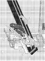
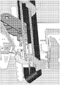
- FIGS. 1 through 3 are perspective views representing a slicing apparatus in accordance with an aspect of this invention.
- the present invention provides a slicing apparatus that may be, though is not required to be, a variation or adaptation of the TRANSLICER® series of machines.
- the slicing apparatus is well suited for slicing an elongate food product 10 with the use of a slicing wheel 12 disposed in a vertical plane and rotated on a horizontal axis, as the product 10 is horizontally delivered to the slicing wheel 10.
- the slicing wheel 12 can be in the form of a disk-shaped blade oriented to produce a lengthwise slice cut 22 in the food product 10 as it is delivered horizontally to the slicing wheel 12.
- FIGS. 1 through 3 shows the product 10 as being delivered while supported on a channel 14 or another suitable stationary delivery structure, which operates in combination with an overhead hold-down device 16.
- the hold-down device 16 is represented as a conveyor belt unit in FIGS. 1 through 3 , though other moving delivery devices could also be used.
- the channel 14 is further shown as having a V-shaped cross-sectional shape and operating in combination with a conveyor belt 24 that is supported by and travels on one of two legs of the V-shaped channel 14.
- a second conveyor belt rides on the second of the two legs of the V-shaped channel 14, such that the product 10 is entirely supported on two moving delivery devices (belts 24).
- the product 10 could be supported solely by the stationary channel 14, or that only one belt 24 could be employed.
- the wheel 12 can be seen to produce the slice cut 22 in the food product 10 parallel to the length of the product 10 and parallel to the direction in which the product 10 is delivered to the wheel 12 on the channel 14.
- the product 10 has a circular cross-section and the slice cut 22 is a diametrical cut that passes entirely through the product 10 so as to halve the product 10.
- the invention is not limited to any particular type of cut, for example, the slice cut 22 could lie on a chord of the circular cross-section of the product 10, or the product 10 could have a cross-section other than circular.
- FIGS. 1 through 3 depict the inclusion of an optional comb/stripper plate 26 adapted to maintain stability/control of the sliced product 10 as and after it leaves the wheel 12, particularly such that the product 10 continues its forward momentum as it exits the slicing apparatus.
- the overhead hold-down device 16 can be seen to be an integral hold-down device that presses the product 10 against the channel 14 and/or belts 24, and simultaneously propels the product 10 along the length of the channel 14 into engagement with the wheel 12.
- the arrangement of the slicing wheel 12 and hold-down device 16 necessitates that the hold-down device 16 comprises at least two belts 18, at least one of which is to either side of the slicing wheel 12 so that the wheel 12 is able to rotate within a gap 20 between the belts 18 without interference from either belt 18.
- Suitable tensioning devices can be used to ensure proper operation of the hold-down device 16 in relation to the wheel 12 and channel 14.
- the speeds and positions of the slicing wheel 12 and hold-down device 16 can be synchronized by mounting the wheel 12 to one of the spindles 28 on which the belts 18 are mounted.
- the product delivery speed of the hold-down device 16 can be synchronized to the rotational speed of the wheel 12, and the slicing depth of the wheel 12 can be synchronized with the position of the hold-down device 16 as the latter applies a downward force to the product 10 and the product 10 is sliced by the wheel 12.
- the hold-down device 16 thereby serves to help maintain the correct speed of the product 10 as it travels through the wheel 12 and maximize product contact with the belts 18.
- halve is used above to reflect the orientation and positioning of the slicing wheel 12 as shown in FIGS. 1 through 3 , in which the slicing wheel 12 roughly bisects an angle defined by the legs of the V-shaped support surfaces defined by the channel 14 and/or belts 24 (or other suitable moving and/or stationary structures) so as to roughly halve the product 10 lengthwise.
- the wheel 12 could have different angular orientations relative to the channel 14. Further processing can be performed on the product downstream of the wheel 12, such as with cutting knives similar to the type employed by the TRANSLICER® series of machines. Additional possible features of the apparatus can be appreciated from FIGS. 1 through 3 .
Landscapes
- Life Sciences & Earth Sciences (AREA)
- Forests & Forestry (AREA)
- Engineering & Computer Science (AREA)
- Mechanical Engineering (AREA)
- Details Of Cutting Devices (AREA)
- Formation And Processing Of Food Products (AREA)
Claims (15)
- Schneidvorrichtung, die Folgendes umfasst:ein Schneidrad (12), das um eine etwa horizontale Achse drehbar gelagert ist;eine erste Zufuhrstruktur (14), die dafür ausgelegt ist, Lebensmittelprodukte (10) dem Schneidrad (12) zuzuführen;eine bewegliche Zufuhrvorrichtung (16), die dafür ausgelegt ist, das Lebensmittelprodukt (10) gegen die erste Zufuhrstruktur (14) zu drücken und das Lebensmittelprodukt (10) in einer Zufuhrrichtung entlang einer Länge der ersten Zufuhrstruktur (14) zu dem Schneidrad (12) vorzuschieben;wobei das Schneidrad (12) in dem Lebensmittelprodukt (10) parallel zur Zufuhrrichtung einen Scheibenschnitt (22) erzeugt, wobei das Lebensmittelprodukt (10) dem Schneidrad (12) zugeführt wird, gekennzeichnet durch:eine Abstreifplatte (26), die dafür ausgelegt ist, die Stabilität und Kontrolle des Lebensmittelprodukts (10) aufrecht zu erhalten, wenn das Lebensmittelprodukt (10) das Schneidrad (12) verlässt und nachdem es dieses verlassen hat, so dass das Lebensmittelprodukt (10) beim Austreten aus dem Schneidrad (12) eine Vorwärtsdynamik fortsetzt;einen Rahmen, auf dem das Schneidrad (12), die bewegliche Zufuhrvorrichtung (16) und die Abstreifplatte (26) angeordnet sind; undein Mittel zum Vorspannen des Rahmens zu der ersten Zufuhrstruktur (14), so dass die bewegliche Zufuhr (16) und die Abstreifplatte (26) gleichzeitig in Richtung des Lebensmittelprodukts gedrückt werden.
- Schneidvorrichtung nach Anspruch 1, wobei die erste Zufuhrstruktur (14) einen Kanal mit einer V-förmigen Querschnittsform aufweist, die durch zwei Schenkel definiert ist.
- Schneidvorrichtung nach Anspruch 2, wobei die erste Zufuhrstruktur (14) ferner mindestens ein Förderband (24) umfasst, das von einem ersten der beiden Schenkel des Kanals gestützt wird und sich auf diesem bewegt.
- Schneidvorrichtung nach Anspruch 3, wobei die erste Zufuhrstruktur (14) ferner mindestens ein zweites Förderband umfasst, das von einem zweiten der beiden Schenkel des Kanals gestützt wird und sich auf diesem bewegt.
- Schneidvorrichtung nach einem der Ansprüche 2 bis 4, wobei das Schneidrad (12) einen Winkel zweiteilt, der durch die V-förmige Querschnittsform definiert ist, die durch die beiden Schenkel des Kanals definiert ist.
- Schneidvorrichtung nach Anspruch 1 oder 2, wobei die bewegliche Zufuhrvorrichtung (16) eine Fördereinheit umfasst, die mindestens erste und zweite Bänder (18) umfasst, wobei mindestens eines davon auf beiden Seiten des Schneidrades (12) angeordnet ist und sich das Schneidrad (12) innerhalb eines Spaltes (20) zwischen dem ersten und dem zweiten Band (18) dreht.
- Schneidvorrichtung nach Anspruch 6, wobei das Schneidrad (12) und das erste und das zweite Band (18) auf einer Spindel (28) montiert sind, um eine Zufuhrgeschwindigkeit des Lebensmittelprodukts (10) mit einer Drehzahl des Schneidrades (12) zu synchronisieren.
- Schneidvorrichtung nach Anspruch 1, wobei die bewegliche Zufuhrvorrichtung (16) ferner dafür ausgelegt ist, die Stabilität und Kontrolle des Lebensmittelprodukts (10) aufrecht zu erhalten, wenn das Lebensmittelprodukt (10) das Schneidrad (12) berührt, und die Abstreifplatte ferner dafür ausgelegt ist, das Lebensmittelprodukt (10) gegen die erste Zufuhrstruktur (14) zu drücken.
- Verfahren zum Schneiden eines Lebensmittelprodukts (10), wobei das Verfahren Folgendes umfasst:Anordnen eines Lebensmittelprodukts (10) auf einer ersten Zufuhrstruktur (14);Drehen eines Schneidrades (12);Vorspannen einer Anordnung, die das Schneidrad (12) umfasst, wobei eine Abstreifplatte (26) dafür ausgelegt ist, die Stabilität und Kontrolle des Lebensmittelprodukts (10) aufrecht zu erhalten, wenn das Lebensmittelprodukt (10) das Schneidrad (12) verlässt und nachdem es dieses verlassen hat, so dass das Lebensmittelprodukt (10) beim Austreten aus dem Schneidrad (12) eine Vorwärtsdynamik fortsetzt,und eine bewegliche Zufuhrvorrichtung (16) in Richtung der ersten Zufuhrstruktur (14) die Abstreifplatte (26) und die bewegliche Zufuhrvorrichtung (16) in Richtung des Lebensmittelprodukts (10) vorspannt; undSchneiden des Lebensmittelprodukts (10) durch Veranlassen der ersten Zufuhrstruktur (14), das Lebensmittelprodukt (10) dem Schneidrad (12) zuzuführen, während die bewegliche Zufuhrvorrichtung (16) einen Druck auf eine gesamte Länge des Lebensmittelprodukts (10) ausübt, um die Krümmung des Lebensmittelprodukts (10) zu verringern, während die gesamte Länge des Lebensmittelprodukts (10) von der ersten Zufuhrstruktur (14) getragen wird.
- Verfahren nach Anspruch 9, wobei die erste Zufuhrstruktur (14) einen Kanal umfasst, der eine V-förmige Querschnittsform aufweist, die durch zwei Schenkel definiert ist, wobei die erste Zufuhrstruktur (14) ferner mindestens ein Förderband (24) umfasst, das von einem ersten der beiden Schenkel des Kanals gestützt wird und sich auf diesem bewegt, und das Verfahren ferner das Tragen des Lebensmittelprodukts (10) mit dem Kanal umfasst, während das Lebensmittelprodukt (10) mit dem Förderband (24) während des Schneidschrittes transportiert wird.
- Verfahren nach Anspruch 10, wobei die erste Zufuhrstruktur (14) ferner mindestens ein zweites Förderband umfasst, das von einem zweiten der beiden Schenkel des Kanals abgestützt wird und sich auf diesem bewegt.
- Verfahren nach Anspruch 10, wobei das Schneidrad (12) einen Winkel zweiteilt, der durch die V-förmige Querschnittsform definiert ist, die durch die beiden Schenkel des Kanals definiert ist.
- Verfahren nach Anspruch 9, wobei die bewegliche Zufuhrvorrichtung (16) eine Fördereinheit umfasst, die mindestens erste und zweite Bänder (18) umfasst, wobei mindestens eines davon auf beiden Seiten des Schneidrades (12) angeordnet ist und sich das Schneidrad (12) innerhalb eines Spaltes (20) zwischen dem ersten und dem zweiten Band dreht.
- Verfahren nach Anspruch 13, wobei das Schneidrad (12) und das erste und das zweite Band (18) auf einer Spindel (28) montiert sind und das Verfahren das Synchronisieren einer Zufuhrgeschwindigkeit des Lebensmittelprodukts (10) mit einer Drehzahl des Schneidrades (12) umfasst.
- Verfahren nach einem der Ansprüche 9 bis 14, das ferner das Aufrechterhalten der Stabilität und Kontrolle des Lebensmittelprodukts (10) mit der Abstreifplatte (26) umfasst, wenn das Lebensmittelprodukt (10) das Schneidrad (12) verlässt und nachdem es dieses verlassen hat, so dass das Lebensmittelprodukt (10) beim Austreten aus dem Schneidrad (12) eine Vorwärtsdynamik fortsetzt.
Applications Claiming Priority (2)
| Application Number | Priority Date | Filing Date | Title |
|---|---|---|---|
| US201261722360P | 2012-11-05 | 2012-11-05 | |
| PCT/US2013/068444 WO2014071356A1 (en) | 2012-11-05 | 2013-11-05 | Slicing apparatus and slicing method |
Publications (3)
| Publication Number | Publication Date |
|---|---|
| EP2914406A1 EP2914406A1 (de) | 2015-09-09 |
| EP2914406A4 EP2914406A4 (de) | 2016-07-06 |
| EP2914406B1 true EP2914406B1 (de) | 2017-05-03 |
Family
ID=50621152
Family Applications (1)
| Application Number | Title | Priority Date | Filing Date |
|---|---|---|---|
| EP13850761.1A Active EP2914406B1 (de) | 2012-11-05 | 2013-11-05 | Scheibenschneidevorrichtung und scheibenschneideverfahren |
Country Status (8)
| Country | Link |
|---|---|
| US (1) | US20140123823A1 (de) |
| EP (1) | EP2914406B1 (de) |
| AU (2) | AU2013337275A1 (de) |
| CA (1) | CA2890167C (de) |
| ES (1) | ES2626065T3 (de) |
| PL (1) | PL2914406T3 (de) |
| PT (1) | PT2914406T (de) |
| WO (1) | WO2014071356A1 (de) |
Families Citing this family (3)
| Publication number | Priority date | Publication date | Assignee | Title |
|---|---|---|---|---|
| CN106042030B (zh) * | 2016-07-08 | 2018-03-27 | 长阳清江农机制造有限公司 | 轮盘式木瓜纵向定位剖切机 |
| CN114986589A (zh) * | 2021-03-01 | 2022-09-02 | 上海索米自动化设备有限公司 | 一种金针菇分切机 |
| CN115366169A (zh) * | 2022-09-02 | 2022-11-22 | 安徽迈明亚克力科技有限公司 | 一种亚克力板快速裁切设备 |
Family Cites Families (15)
| Publication number | Priority date | Publication date | Assignee | Title |
|---|---|---|---|---|
| US1529806A (en) * | 1924-01-12 | 1925-03-17 | Paul G Oettel | Match-block-sawing machine |
| US2603262A (en) * | 1948-01-29 | 1952-07-15 | William E Urschel | Sectionalizing cutting machine |
| US3495487A (en) * | 1967-01-09 | 1970-02-17 | William W Miner | Method of and apparatus for slitting sod pads |
| US3502127A (en) * | 1967-12-11 | 1970-03-24 | Doro Mayo Equipment Co Inc | Meat cutting machine |
| DE2514836C2 (de) * | 1975-04-04 | 1985-01-31 | Maschinenbau Oppenweiler Gmbh, 7155 Oppenweiler | Vorrichtung zum Durchschneiden eines Bogenstapels mit einem Rundmesser |
| US3972255A (en) * | 1975-09-15 | 1976-08-03 | Alto Corporation | Bakery product slicer |
| US4163406A (en) * | 1977-12-15 | 1979-08-07 | Genevieve I. Hanscom | Centering device for feeding articles to a food slicer |
| JPS6043114B2 (ja) * | 1982-12-24 | 1985-09-26 | 日本たばこ産業株式会社 | 裁断装置 |
| GB8501756D0 (en) * | 1985-01-24 | 1985-02-27 | Svecia Antiqua Ltd | Production of paper |
| US5271304A (en) | 1990-07-03 | 1993-12-21 | Carruthers Equipment Co. | Automatic food slicing machine |
| US6634282B1 (en) * | 2000-02-23 | 2003-10-21 | Henry B. Whitmore | Sandwich machine |
| US7100486B2 (en) * | 2003-07-08 | 2006-09-05 | Leprino Foods Company | Apparatus for dicing a deformable product |
| ITRM20040263A1 (it) * | 2004-05-28 | 2004-08-28 | Turatti Srl | Dispositivo o taglierina per il taglio in quarti di prodotti alimentari e non. |
| US20120064214A1 (en) * | 2007-08-27 | 2012-03-15 | Richard Moore | Avocado Cutting and Splitting Device |
| US20090056519A1 (en) * | 2007-08-27 | 2009-03-05 | Moore Richard E | Avocado cutting and splitting device |
-
2013
- 2013-11-05 ES ES13850761.1T patent/ES2626065T3/es active Active
- 2013-11-05 CA CA2890167A patent/CA2890167C/en active Active
- 2013-11-05 US US14/072,059 patent/US20140123823A1/en not_active Abandoned
- 2013-11-05 PL PL13850761T patent/PL2914406T3/pl unknown
- 2013-11-05 EP EP13850761.1A patent/EP2914406B1/de active Active
- 2013-11-05 WO PCT/US2013/068444 patent/WO2014071356A1/en not_active Ceased
- 2013-11-05 AU AU2013337275A patent/AU2013337275A1/en not_active Abandoned
- 2013-11-05 PT PT138507611T patent/PT2914406T/pt unknown
-
2016
- 2016-12-05 AU AU2016269399A patent/AU2016269399B2/en active Active
Non-Patent Citations (1)
| Title |
|---|
| None * |
Also Published As
| Publication number | Publication date |
|---|---|
| AU2016269399A1 (en) | 2016-12-22 |
| CA2890167C (en) | 2017-12-12 |
| EP2914406A1 (de) | 2015-09-09 |
| EP2914406A4 (de) | 2016-07-06 |
| ES2626065T3 (es) | 2017-07-21 |
| WO2014071356A1 (en) | 2014-05-08 |
| PL2914406T3 (pl) | 2017-09-29 |
| AU2013337275A1 (en) | 2015-05-07 |
| CA2890167A1 (en) | 2014-05-08 |
| AU2016269399B2 (en) | 2018-10-04 |
| US20140123823A1 (en) | 2014-05-08 |
| PT2914406T (pt) | 2017-08-03 |
Similar Documents
| Publication | Publication Date | Title |
|---|---|---|
| US6314849B1 (en) | Dicing machine with improved cutting squareness | |
| US9981400B2 (en) | Apparatus for slicing food products and method of providing intermediate sheets | |
| EP3307499B1 (de) | Maschinen und verfahren zum schneiden von produkten | |
| EP0759837B1 (de) | Schneidmesser für ein Rotationsgerät zum Schneiden eines Nahrungsmittels und Rotationschneidgerät | |
| US10933550B2 (en) | Size-reduction machine and size-reduction unit therefor | |
| US4163406A (en) | Centering device for feeding articles to a food slicer | |
| EP3528956B1 (de) | Grössenverringerungsmaschinen, zuführeinheiten dafür und verfahren zur verwendung | |
| EP3071380A1 (de) | Messeranordnung für flache messerklinge und schneidesystem damit | |
| JP2019063987A (ja) | 製品切断用の切断ホイールおよびナイフアセンブリ | |
| AU2013322554A1 (en) | Device and method for continuously producing portions | |
| AU2016269399B2 (en) | Slicing Apparatus and Slicing Method | |
| CN104786264B (zh) | 全自动变频切花机 | |
| US11667047B2 (en) | Blade, slicing machine equipped therewith and method of operating the slicing machine | |
| CN104942850B (zh) | 切片机以及切笋片的方法 | |
| CN118493504A (zh) | 一种三维肉类滚筒切丁机 |
Legal Events
| Date | Code | Title | Description |
|---|---|---|---|
| PUAI | Public reference made under article 153(3) epc to a published international application that has entered the european phase |
Free format text: ORIGINAL CODE: 0009012 |
|
| 17P | Request for examination filed |
Effective date: 20150417 |
|
| AK | Designated contracting states |
Kind code of ref document: A1 Designated state(s): AL AT BE BG CH CY CZ DE DK EE ES FI FR GB GR HR HU IE IS IT LI LT LU LV MC MK MT NL NO PL PT RO RS SE SI SK SM TR |
|
| AX | Request for extension of the european patent |
Extension state: BA ME |
|
| DAX | Request for extension of the european patent (deleted) | ||
| RA4 | Supplementary search report drawn up and despatched (corrected) |
Effective date: 20160602 |
|
| RIC1 | Information provided on ipc code assigned before grant |
Ipc: B26D 7/01 20060101ALI20160527BHEP Ipc: B26D 1/14 20060101ALI20160527BHEP Ipc: B26D 3/26 20060101AFI20160527BHEP |
|
| GRAP | Despatch of communication of intention to grant a patent |
Free format text: ORIGINAL CODE: EPIDOSNIGR1 |
|
| INTG | Intention to grant announced |
Effective date: 20170208 |
|
| GRAS | Grant fee paid |
Free format text: ORIGINAL CODE: EPIDOSNIGR3 |
|
| GRAA | (expected) grant |
Free format text: ORIGINAL CODE: 0009210 |
|
| RAP1 | Party data changed (applicant data changed or rights of an application transferred) |
Owner name: URSCHEL LABORATORIES, INC. |
|
| AK | Designated contracting states |
Kind code of ref document: B1 Designated state(s): AL AT BE BG CH CY CZ DE DK EE ES FI FR GB GR HR HU IE IS IT LI LT LU LV MC MK MT NL NO PL PT RO RS SE SI SK SM TR |
|
| REG | Reference to a national code |
Ref country code: GB Ref legal event code: FG4D |
|
| REG | Reference to a national code |
Ref country code: AT Ref legal event code: REF Ref document number: 889472 Country of ref document: AT Kind code of ref document: T Effective date: 20170515 Ref country code: CH Ref legal event code: EP |
|
| REG | Reference to a national code |
Ref country code: IE Ref legal event code: FG4D |
|
| REG | Reference to a national code |
Ref country code: DE Ref legal event code: R096 Ref document number: 602013020810 Country of ref document: DE |
|
| REG | Reference to a national code |
Ref country code: ES Ref legal event code: FG2A Ref document number: 2626065 Country of ref document: ES Kind code of ref document: T3 Effective date: 20170721 |
|
| REG | Reference to a national code |
Ref country code: NL Ref legal event code: FP |
|
| REG | Reference to a national code |
Ref country code: PT Ref legal event code: SC4A Ref document number: 2914406 Country of ref document: PT Date of ref document: 20170803 Kind code of ref document: T Free format text: AVAILABILITY OF NATIONAL TRANSLATION Effective date: 20170727 |
|
| REG | Reference to a national code |
Ref country code: AT Ref legal event code: MK05 Ref document number: 889472 Country of ref document: AT Kind code of ref document: T Effective date: 20170503 |
|
| REG | Reference to a national code |
Ref country code: LT Ref legal event code: MG4D |
|
| PG25 | Lapsed in a contracting state [announced via postgrant information from national office to epo] |
Ref country code: LT Free format text: LAPSE BECAUSE OF FAILURE TO SUBMIT A TRANSLATION OF THE DESCRIPTION OR TO PAY THE FEE WITHIN THE PRESCRIBED TIME-LIMIT Effective date: 20170503 Ref country code: NO Free format text: LAPSE BECAUSE OF FAILURE TO SUBMIT A TRANSLATION OF THE DESCRIPTION OR TO PAY THE FEE WITHIN THE PRESCRIBED TIME-LIMIT Effective date: 20170803 Ref country code: FI Free format text: LAPSE BECAUSE OF FAILURE TO SUBMIT A TRANSLATION OF THE DESCRIPTION OR TO PAY THE FEE WITHIN THE PRESCRIBED TIME-LIMIT Effective date: 20170503 Ref country code: HR Free format text: LAPSE BECAUSE OF FAILURE TO SUBMIT A TRANSLATION OF THE DESCRIPTION OR TO PAY THE FEE WITHIN THE PRESCRIBED TIME-LIMIT Effective date: 20170503 Ref country code: AT Free format text: LAPSE BECAUSE OF FAILURE TO SUBMIT A TRANSLATION OF THE DESCRIPTION OR TO PAY THE FEE WITHIN THE PRESCRIBED TIME-LIMIT Effective date: 20170503 Ref country code: GR Free format text: LAPSE BECAUSE OF FAILURE TO SUBMIT A TRANSLATION OF THE DESCRIPTION OR TO PAY THE FEE WITHIN THE PRESCRIBED TIME-LIMIT Effective date: 20170804 |
|
| REG | Reference to a national code |
Ref country code: FR Ref legal event code: PLFP Year of fee payment: 5 |
|
| PG25 | Lapsed in a contracting state [announced via postgrant information from national office to epo] |
Ref country code: RS Free format text: LAPSE BECAUSE OF FAILURE TO SUBMIT A TRANSLATION OF THE DESCRIPTION OR TO PAY THE FEE WITHIN THE PRESCRIBED TIME-LIMIT Effective date: 20170503 Ref country code: LV Free format text: LAPSE BECAUSE OF FAILURE TO SUBMIT A TRANSLATION OF THE DESCRIPTION OR TO PAY THE FEE WITHIN THE PRESCRIBED TIME-LIMIT Effective date: 20170503 Ref country code: BG Free format text: LAPSE BECAUSE OF FAILURE TO SUBMIT A TRANSLATION OF THE DESCRIPTION OR TO PAY THE FEE WITHIN THE PRESCRIBED TIME-LIMIT Effective date: 20170803 Ref country code: SE Free format text: LAPSE BECAUSE OF FAILURE TO SUBMIT A TRANSLATION OF THE DESCRIPTION OR TO PAY THE FEE WITHIN THE PRESCRIBED TIME-LIMIT Effective date: 20170503 Ref country code: IS Free format text: LAPSE BECAUSE OF FAILURE TO SUBMIT A TRANSLATION OF THE DESCRIPTION OR TO PAY THE FEE WITHIN THE PRESCRIBED TIME-LIMIT Effective date: 20170903 |
|
| PG25 | Lapsed in a contracting state [announced via postgrant information from national office to epo] |
Ref country code: RO Free format text: LAPSE BECAUSE OF FAILURE TO SUBMIT A TRANSLATION OF THE DESCRIPTION OR TO PAY THE FEE WITHIN THE PRESCRIBED TIME-LIMIT Effective date: 20170503 Ref country code: CZ Free format text: LAPSE BECAUSE OF FAILURE TO SUBMIT A TRANSLATION OF THE DESCRIPTION OR TO PAY THE FEE WITHIN THE PRESCRIBED TIME-LIMIT Effective date: 20170503 Ref country code: SK Free format text: LAPSE BECAUSE OF FAILURE TO SUBMIT A TRANSLATION OF THE DESCRIPTION OR TO PAY THE FEE WITHIN THE PRESCRIBED TIME-LIMIT Effective date: 20170503 Ref country code: DK Free format text: LAPSE BECAUSE OF FAILURE TO SUBMIT A TRANSLATION OF THE DESCRIPTION OR TO PAY THE FEE WITHIN THE PRESCRIBED TIME-LIMIT Effective date: 20170503 Ref country code: EE Free format text: LAPSE BECAUSE OF FAILURE TO SUBMIT A TRANSLATION OF THE DESCRIPTION OR TO PAY THE FEE WITHIN THE PRESCRIBED TIME-LIMIT Effective date: 20170503 |
|
| REG | Reference to a national code |
Ref country code: DE Ref legal event code: R097 Ref document number: 602013020810 Country of ref document: DE |
|
| PG25 | Lapsed in a contracting state [announced via postgrant information from national office to epo] |
Ref country code: SM Free format text: LAPSE BECAUSE OF FAILURE TO SUBMIT A TRANSLATION OF THE DESCRIPTION OR TO PAY THE FEE WITHIN THE PRESCRIBED TIME-LIMIT Effective date: 20170503 |
|
| PLBE | No opposition filed within time limit |
Free format text: ORIGINAL CODE: 0009261 |
|
| STAA | Information on the status of an ep patent application or granted ep patent |
Free format text: STATUS: NO OPPOSITION FILED WITHIN TIME LIMIT |
|
| 26N | No opposition filed |
Effective date: 20180206 |
|
| PG25 | Lapsed in a contracting state [announced via postgrant information from national office to epo] |
Ref country code: SI Free format text: LAPSE BECAUSE OF FAILURE TO SUBMIT A TRANSLATION OF THE DESCRIPTION OR TO PAY THE FEE WITHIN THE PRESCRIBED TIME-LIMIT Effective date: 20170503 |
|
| PG25 | Lapsed in a contracting state [announced via postgrant information from national office to epo] |
Ref country code: MC Free format text: LAPSE BECAUSE OF FAILURE TO SUBMIT A TRANSLATION OF THE DESCRIPTION OR TO PAY THE FEE WITHIN THE PRESCRIBED TIME-LIMIT Effective date: 20170503 |
|
| PG25 | Lapsed in a contracting state [announced via postgrant information from national office to epo] |
Ref country code: LI Free format text: LAPSE BECAUSE OF NON-PAYMENT OF DUE FEES Effective date: 20171130 Ref country code: CH Free format text: LAPSE BECAUSE OF NON-PAYMENT OF DUE FEES Effective date: 20171130 |
|
| PG25 | Lapsed in a contracting state [announced via postgrant information from national office to epo] |
Ref country code: LU Free format text: LAPSE BECAUSE OF NON-PAYMENT OF DUE FEES Effective date: 20171105 |
|
| REG | Reference to a national code |
Ref country code: IE Ref legal event code: MM4A |
|
| PG25 | Lapsed in a contracting state [announced via postgrant information from national office to epo] |
Ref country code: MT Free format text: LAPSE BECAUSE OF NON-PAYMENT OF DUE FEES Effective date: 20171105 |
|
| PG25 | Lapsed in a contracting state [announced via postgrant information from national office to epo] |
Ref country code: IE Free format text: LAPSE BECAUSE OF NON-PAYMENT OF DUE FEES Effective date: 20171105 |
|
| PG25 | Lapsed in a contracting state [announced via postgrant information from national office to epo] |
Ref country code: HU Free format text: LAPSE BECAUSE OF FAILURE TO SUBMIT A TRANSLATION OF THE DESCRIPTION OR TO PAY THE FEE WITHIN THE PRESCRIBED TIME-LIMIT; INVALID AB INITIO Effective date: 20131105 |
|
| PG25 | Lapsed in a contracting state [announced via postgrant information from national office to epo] |
Ref country code: CY Free format text: LAPSE BECAUSE OF FAILURE TO SUBMIT A TRANSLATION OF THE DESCRIPTION OR TO PAY THE FEE WITHIN THE PRESCRIBED TIME-LIMIT Effective date: 20170503 |
|
| PG25 | Lapsed in a contracting state [announced via postgrant information from national office to epo] |
Ref country code: MK Free format text: LAPSE BECAUSE OF FAILURE TO SUBMIT A TRANSLATION OF THE DESCRIPTION OR TO PAY THE FEE WITHIN THE PRESCRIBED TIME-LIMIT Effective date: 20170503 |
|
| PG25 | Lapsed in a contracting state [announced via postgrant information from national office to epo] |
Ref country code: TR Free format text: LAPSE BECAUSE OF FAILURE TO SUBMIT A TRANSLATION OF THE DESCRIPTION OR TO PAY THE FEE WITHIN THE PRESCRIBED TIME-LIMIT Effective date: 20170503 |
|
| PG25 | Lapsed in a contracting state [announced via postgrant information from national office to epo] |
Ref country code: AL Free format text: LAPSE BECAUSE OF FAILURE TO SUBMIT A TRANSLATION OF THE DESCRIPTION OR TO PAY THE FEE WITHIN THE PRESCRIBED TIME-LIMIT Effective date: 20170503 |
|
| P01 | Opt-out of the competence of the unified patent court (upc) registered |
Free format text: CASE NUMBER: APP_42757/2024 Effective date: 20240719 |
|
| PGFP | Annual fee paid to national office [announced via postgrant information from national office to epo] |
Ref country code: PT Payment date: 20251029 Year of fee payment: 13 |
|
| PGFP | Annual fee paid to national office [announced via postgrant information from national office to epo] |
Ref country code: NL Payment date: 20251114 Year of fee payment: 13 |
|
| PGFP | Annual fee paid to national office [announced via postgrant information from national office to epo] |
Ref country code: DE Payment date: 20251114 Year of fee payment: 13 |
|
| PGFP | Annual fee paid to national office [announced via postgrant information from national office to epo] |
Ref country code: GB Payment date: 20251119 Year of fee payment: 13 |
|
| PGFP | Annual fee paid to national office [announced via postgrant information from national office to epo] |
Ref country code: IT Payment date: 20251114 Year of fee payment: 13 |
|
| PGFP | Annual fee paid to national office [announced via postgrant information from national office to epo] |
Ref country code: FR Payment date: 20251125 Year of fee payment: 13 |
|
| PGFP | Annual fee paid to national office [announced via postgrant information from national office to epo] |
Ref country code: BE Payment date: 20251114 Year of fee payment: 13 |
|
| PGFP | Annual fee paid to national office [announced via postgrant information from national office to epo] |
Ref country code: PL Payment date: 20251030 Year of fee payment: 13 |
|
| PGFP | Annual fee paid to national office [announced via postgrant information from national office to epo] |
Ref country code: ES Payment date: 20251216 Year of fee payment: 13 |