EP2914873B1 - Schaltanordnung für ein doppelkupplungsgetriebe - Google Patents
Schaltanordnung für ein doppelkupplungsgetriebe Download PDFInfo
- Publication number
- EP2914873B1 EP2914873B1 EP13780072.8A EP13780072A EP2914873B1 EP 2914873 B1 EP2914873 B1 EP 2914873B1 EP 13780072 A EP13780072 A EP 13780072A EP 2914873 B1 EP2914873 B1 EP 2914873B1
- Authority
- EP
- European Patent Office
- Prior art keywords
- clutch
- gear
- partial
- gearbox
- planetary gear
- Prior art date
- Legal status (The legal status is an assumption and is not a legal conclusion. Google has not performed a legal analysis and makes no representation as to the accuracy of the status listed.)
- Not-in-force
Links
Images


Classifications
-
- F—MECHANICAL ENGINEERING; LIGHTING; HEATING; WEAPONS; BLASTING
- F16—ENGINEERING ELEMENTS AND UNITS; GENERAL MEASURES FOR PRODUCING AND MAINTAINING EFFECTIVE FUNCTIONING OF MACHINES OR INSTALLATIONS; THERMAL INSULATION IN GENERAL
- F16H—GEARING
- F16H37/00—Combinations of mechanical gearings, not provided for in groups F16H1/00 - F16H35/00
- F16H37/02—Combinations of mechanical gearings, not provided for in groups F16H1/00 - F16H35/00 comprising essentially only toothed or friction gearings
- F16H37/04—Combinations of toothed gearings only
- F16H37/042—Combinations of toothed gearings only change gear transmissions in group arrangement
- F16H37/046—Combinations of toothed gearings only change gear transmissions in group arrangement with an additional planetary gear train, e.g. creep gear, overdrive
-
- F—MECHANICAL ENGINEERING; LIGHTING; HEATING; WEAPONS; BLASTING
- F16—ENGINEERING ELEMENTS AND UNITS; GENERAL MEASURES FOR PRODUCING AND MAINTAINING EFFECTIVE FUNCTIONING OF MACHINES OR INSTALLATIONS; THERMAL INSULATION IN GENERAL
- F16H—GEARING
- F16H3/00—Toothed gearings for conveying rotary motion with variable gear ratio or for reversing rotary motion
- F16H3/006—Toothed gearings for conveying rotary motion with variable gear ratio or for reversing rotary motion power being selectively transmitted by parallel flow paths, e.g. dual clutch transmissions
-
- F—MECHANICAL ENGINEERING; LIGHTING; HEATING; WEAPONS; BLASTING
- F16—ENGINEERING ELEMENTS AND UNITS; GENERAL MEASURES FOR PRODUCING AND MAINTAINING EFFECTIVE FUNCTIONING OF MACHINES OR INSTALLATIONS; THERMAL INSULATION IN GENERAL
- F16H—GEARING
- F16H37/00—Combinations of mechanical gearings, not provided for in groups F16H1/00 - F16H35/00
- F16H37/02—Combinations of mechanical gearings, not provided for in groups F16H1/00 - F16H35/00 comprising essentially only toothed or friction gearings
- F16H37/04—Combinations of toothed gearings only
- F16H37/042—Combinations of toothed gearings only change gear transmissions in group arrangement
-
- F—MECHANICAL ENGINEERING; LIGHTING; HEATING; WEAPONS; BLASTING
- F16—ENGINEERING ELEMENTS AND UNITS; GENERAL MEASURES FOR PRODUCING AND MAINTAINING EFFECTIVE FUNCTIONING OF MACHINES OR INSTALLATIONS; THERMAL INSULATION IN GENERAL
- F16H—GEARING
- F16H37/00—Combinations of mechanical gearings, not provided for in groups F16H1/00 - F16H35/00
- F16H37/02—Combinations of mechanical gearings, not provided for in groups F16H1/00 - F16H35/00 comprising essentially only toothed or friction gearings
- F16H37/04—Combinations of toothed gearings only
- F16H2037/047—Combinations of toothed gearings only comprising one or more orbital gear sets coaxial with a first shaft and having more than one drive connection to a second shaft parallel to the first shaft
-
- F—MECHANICAL ENGINEERING; LIGHTING; HEATING; WEAPONS; BLASTING
- F16—ENGINEERING ELEMENTS AND UNITS; GENERAL MEASURES FOR PRODUCING AND MAINTAINING EFFECTIVE FUNCTIONING OF MACHINES OR INSTALLATIONS; THERMAL INSULATION IN GENERAL
- F16H—GEARING
- F16H2200/00—Transmissions for multiple ratios
- F16H2200/20—Transmissions using gears with orbital motion
- F16H2200/2002—Transmissions using gears with orbital motion characterised by the number of sets of orbital gears
- F16H2200/2007—Transmissions using gears with orbital motion characterised by the number of sets of orbital gears with two sets of orbital gears
-
- F—MECHANICAL ENGINEERING; LIGHTING; HEATING; WEAPONS; BLASTING
- F16—ENGINEERING ELEMENTS AND UNITS; GENERAL MEASURES FOR PRODUCING AND MAINTAINING EFFECTIVE FUNCTIONING OF MACHINES OR INSTALLATIONS; THERMAL INSULATION IN GENERAL
- F16H—GEARING
- F16H2200/00—Transmissions for multiple ratios
- F16H2200/20—Transmissions using gears with orbital motion
- F16H2200/203—Transmissions using gears with orbital motion characterised by the engaging friction means not of the freewheel type, e.g. friction clutches or brakes
- F16H2200/2041—Transmissions using gears with orbital motion characterised by the engaging friction means not of the freewheel type, e.g. friction clutches or brakes with four engaging means
Definitions
- the invention relates to a dual-clutch transmission as a speed change gearbox for motor vehicles according to the preamble of patent claim 1.
- Such dual-clutch transmissions can be used with a good transmission efficiency as an automated manual transmission, which can also be switched quickly and without interruption of the tractive force by dividing it into two partial transmissions and two separating clutches.
- a large transmission spread is desired, which can be realized for example by providing increased forward gears (not too large jumps in translation).
- the object of the invention is to provide a dual-clutch transmission of the generic type, which allows for a structurally compact design, a large gear spread and an increased number of forward gears and the control technology is well controlled.
- From the US 2003/0148847 A1 is a generic dual-clutch transmission known as a speed change gearbox for motor vehicles. From the DE 10 2009 024 240 A1 a transmission arrangement is known. From the DE 10 2006 028 798 A1 is a double clutch transmission known. From the DE 10 2011 005 029 A1 is also known a dual clutch transmission. Out of the DE 10 2006 007 010 A1 is another dual-clutch transmission and a method for switching control of the dual-clutch transmission known. The object is solved with the features of claim 1. Advantageous embodiments and further developments of the invention give the dependent claims.
- the partial transmission A and / or the partial transmission B is assigned at least one ballast unit and / or one rear-end unit, which can be switched over into two different transmission stages.
- the integrated forward and / or Nachschalttician manages to produce a multiplication of the forward gears in the partial transmissions A and B, and despite the thus achievable, larger transmission spread, the number of gear sets can be reduced.
- the overall length of the transmission is not increased and the overhead can be kept relatively low. For example, results in an assignment of a pre- and / or Nachschaltvenez to the partial transmission A thus results in a doubling of the gears of the partial transmission A. In addition, in this case, a larger transmission spread in the partial transmission A can be realized.
- the pre-and / or Nachschaltü may be performed in a non-claimed embodiment generally in a countershaft design, for example as a Performerque, a front or rear group or in any other suitable construction. According to the invention, however, the pre- or Nachschaltvenez is realized as a planetary gear. The invention is thus realized with a switching unit designed as a planetary gear.
- the one planetary gear adjacent the dual clutch K1, K2 on the input hollow shaft of the partial transmission A and the second planetary gear in the power flow behind the gear sets of both partial transmissions A, B be positioned on the output shaft.
- both planetary gear are spatially favorable outside the gear sets of the two partial transmission.
- the translation stages formed by the gear sets can be quadrupled for the partial transmission A and doubled for the partial transmission B, whereby defined gear jumps can be created.
- the one planetary gear can be arranged adjacent to the dual clutch on the input hollow shaft of the partial transmission A and the other planetary gear coaxially on the input shaft of the partial transmission B. This allows a doubling of the gear ratios of both partial transmissions A and B in a structurally particularly compact gear design.
- both planetary gear can be positioned adjacent to the double clutch and immediately one behind the other on the input hollow shaft of the partial transmission A. This allows, where appropriate, the summary of the two planetary gear to a building and assembly unit. Furthermore, the gear ratios of the sub-transmission A can be quadrupled, while the gear ratios of the sub-transmission B, however, are only easy to use.
- the pre-and / or Nachschaltü is generally switchable into two different gear ratios.
- the two gear ratios are a first 1: 1 gear stage and a second, lower (or higher) gear stage.
- Such a planetary gear has an input element, an output element and a via a brake B fixable transmission element for switching the lower gear ratio.
- the planetary gear can be switched via a clutch K3 in the higher 1: 1 gear ratio, the clutch connects two elements of the planetary gear each other.
- the clutch can be a hydraulically actuated multi-disc clutch and the brake can be a hydraulically actuated band brake or similar a multi-disc clutch, so that comfortable, jerk-free switching without traction interruptions are possible.
- the input element of the planetary gear are a ring gear
- the output element is a planetary gear-carrying web
- the transmission element meshing with the planet gears sun gear which can be fixed via the brake B or connectable via the clutch K3 with one of the other elements of the planetary gear.
- the clutch K3 is provided between each of the driving ring gear and the sun gear.
- the brake B and the clutch K3 are structurally simple arranged on a common hollow shaft with the sun gear.
- the two planetary gear are designed substantially identical, but if necessary, have different ratios in the lower gear ratio to realize targeted, adapted to the gear ratios through gear sets gear jumps.
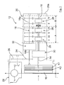
- the Fig. 1 shows roughly schematically a dual-clutch transmission 12 as a speed change gearbox for motor vehicles, with two coaxial transmission input shafts 14, 16, which via two separating clutches K1, K2 with a driving drive unit or an internal combustion engine (not shown) are drivably connectable.
- the input shaft 14 is a hollow shaft executed.
- the dual clutch K1, K2 may be associated with a torsional vibration damper, for example a dual mass flywheel 10.
- an output shaft 18 is arranged, which aborts via spur gears 24, 26 to a front axle differential 22 attached to the transmission housing 20 (only indicated).
- Said shafts 14, 16, 18 are rotatably supported in the transmission housing 20 via only indicated rolling bearings (without reference numerals).
- the dual-clutch transmission 12 is divided into a partial transmission A and a partial transmission B, wherein the input hollow shaft 14 extends only within the partial transmission A, while the input shaft 16 is guided through the input shaft 14 in the partial transmission B to its end wall 20 a.
- sub-transmission A are three forward gear sets I, III, V and a reverse gear set R with an integrated reverse gear (not shown) arranged, which are composed in known manner of fixed gears and idler gears, said idler gears via synchronizer clutches (generally designated 28 ) can be switched.
- two forward gear sets II and IV are provided, which also consist of fixed gears and a synchronous clutch 28 switchable idler gears and form the forward gears in the corresponding translation interpretation.
- the partial transmission A is adjacent to the dual clutch K1, K2 as a ballast, for example, a first planetary gear 30 upstream, which is designed coaxially with the input hollow shaft 14 and which is switchable in two gear ratios or in a lower gear ratio and a higher 1: 1 gear ratio.
- a ballast for example, a first planetary gear 30 upstream, which is designed coaxially with the input hollow shaft 14 and which is switchable in two gear ratios or in a lower gear ratio and a higher 1: 1 gear ratio.
- FIGS. 2 and 3 sketchy show the planetary gear 30 and 32, the matching gear elements are provided with the same reference numerals.
- the attached to the dual clutch K1, K2 planetary gear 30 ( Fig. 2 ) has a ring gear 34 drivingly connected to the clutch K1 as an input element, a web 36 with rotatably mounted planetary gears 38 as an output element and a sun gear 40 as a transmission element.
- the web 36 is drivingly connected directly to the input hollow shaft 14 of the partial transmission A, while the sun gear 40 is connected via a further hollow shaft 42 to the brake B fixed to the housing.
- the brake B is preferably similar to a multi-plate clutch or constructed as a band brake and hydraulically actuated.
- a multi-disc clutch K3 is provided between the ring gear 34 and the hollow shaft 42 and the sun gear 40, which acts hydraulically on the ring gear 34 connects to the sun gear 40 and thus forms the 1: 1 ratio of the planetary gear 30.
- the clutch K1 then drives the hollow shaft 14 of the partial transmission A via the blocked planetary gear 30.
- the planetary gear 30 is switchable by the clutch K3 dissolved and the brake B is actuated. Then, the closed clutch K1 via the ring gear 34, the planet gears 38 and the web 36 drives the input hollow shaft 14, while the sun gear 40 is braked as a support member.
- the planetary gear 32 deviates from the above-described planetary gear 30 only in that it is integrated in the output shaft 18, wherein the fixed gears ( Fig. 1 ) carrying portion 18a of the output shaft 18 to the ring gear 34 and the abrading web 36 with the continuing portion 18b of the output shaft 18 is drivingly connected.
- each gear set I, III, V and the reverse gear set R can be driven in two translations, thus forming eight gears defined translation interpretations.
- the gear sets II and IV can also be driven via the integrated in the output shaft 18 planetary gear 32 in two translations, therefore, another four forward gears.
- the transmission control (not shown) preferably switches without gear interruptions the gear sets of the partial transmission A or the Partial gear B by coupling the synchronizer clutches 28 active and controls the two planetary gear 30, 32 depending on the driving situation in the lower or higher 1: 1 ratio.
- the 4 and 5 show alternative dual clutch transmissions 12 ', 12 ", which are only explained so far, as they move from the dual clutch transmission 12 according to Fig. 1 differ. Functionally identical parts are provided with the same reference numerals.
- the second planetary gear 32 is not integrated in the output shaft 18, but in the second input shaft 16 of the partial transmission B.
- gear sets may be arranged in the partial transmission A and the partial transmission B of the dual clutch transmission.
- the structural conditions are optionally relevant in the arrangement of the two planetary gear 30, 32.
- the ratios of the two planetary gear 30, 32 may be made different in the lower gear stage to realize defined larger or smaller gear jumps.
- the planetary gear 30, 32 may optionally be designed differently for structural or spatial reasons (for example, without ring gear and with a ridge with stepped planetary gears, which mesh with two axially adjacent sun gears).
- the dual-clutch transmission 12 may also be designed for four-wheel drive of the motor vehicle.
- the output shaft 18 may be designed as a hollow shaft, which is on the differential housing of a integrated insectsdifferenziales abters. Their output shafts can then drive a rear axle differential and through the hollow shaft through the front axle differential 22.
Landscapes
- Engineering & Computer Science (AREA)
- General Engineering & Computer Science (AREA)
- Mechanical Engineering (AREA)
- Structure Of Transmissions (AREA)
Description
- Die Erfindung betrifft ein Doppelkupplungsgetriebe als Geschwindigkeits-Wechselgetriebe für Kraftfahrzeuge gemäß dem Oberbegriff des Patentanspruchs 1.
- Derartige Doppelkupplungsgetriebe sind bei einem guten Getriebewirkungsgrad als automatisierte Schaltgetriebe einsetzbar, die zudem durch die Aufteilung auf zwei Teilgetriebe und zwei Trennkupplungen schnell und ohne Unterbrechung der Zugkraft schaltbar sind. In dem Bestreben, derartige Wechselgetriebe optimal an die Antriebsleistungen der Antriebsaggregate bzw. von Brennkraftmaschinen anzupassen, ist eine große Getriebespreizung erwünscht, die zum Beispiel durch das Vorsehen vermehrter Vorwärtsgänge (bei nicht zu großen Übersetzungssprüngen) realisiert werden kann.
- Aufgabe der Erfindung ist es, ein Doppelkupplungsgetriebe der gattungsgemäßen Art anzugeben, das bei einer baulich kompakten Konstruktion eine große Getriebespreizung und eine erhöhte Anzahl von Vorwärtsgängen ermöglicht und das steuerungstechnisch gut beherrschbar ist.
- Aus der
US 2003/0148847 A1 ist ein gattungsgemäßes Doppelkupplungsgetriebe als Geschwindigkeits-Wechselgetriebe für Kraftfahrzeuge bekannt. Aus derDE 10 2009 024 240 A1 ist eine Getriebeanordnung bekannt. Aus derDE 10 2006 028 798 A1 ist ein Doppelkupplungsgetriebe bekannt. Aus derDE 10 2011 005 029 A1 ist ebenfalls ein Doppelkupplungsgetriebe bekannt. Aus derDE 10 2006 007 010 A1 ist ein weiteres Doppelkupplungsgetriebe sowie ein Verfahren zur Schaltsteuerung des Doppelkupplungsgetriebes bekannt. Die Aufgabe ist mit den Merkmalen des Patentanspruchs 1 gelöst. Vorteilhafte Ausgestaltungen und Weiterbildungen der Erfindung geben die abhängigen Ansprüche an. - Erfindungsgemäß ist dem Teilgetriebe A und/oder dem Teilgetriebe B zumindest eine Vorschalteinheit und/oder eine Nachschalteinheit zugeordnet, die in zwei unterschiedliche Übersetzungsstufen umschaltbar ist. Durch die integrierte Vor- und/oder Nachschalteinheit gelingt es, in den Teilgetrieben A und B eine Vervielfachung der Vorwärtsgänge herzustellen, wobei trotz der damit verwirklichbaren, größeren Getriebespreizung die Anzahl der Zahnradsätze verringert werden kann. Dabei wird die Baulänge des Getriebes nicht vergrößert und der Mehraufwand kann relativ gering gehalten werden. Beispielsweise ergibt sich bei einer Zuordnung einer Vor- und/oder Nachschalteinheit zum Teilgetriebe A ergibt sich somit eine Verdoppelung der Gänge des Teilgetriebes A. Zudem ist in diesem Fall auch eine größere Getriebespreizung im Teilgetriebe A realisierbar.
- Die Vor- und/oder Nachschalteinheit kann in einer nicht beanspruchten Ausführungsform generell in einer Vorgelege-Bauweise ausgeführt sein, beispielsweise als eine Performerstufe, eine Vor- oder Nachschaltgruppe oder in einer anderen geeigneten Bauweise. Erfindungsgemäß jedoch ist die Vor- oder Nachschalteinheit als ein Planetengetriebe realisiert. Die Erfindung ist somit mit einer als Planetengetriebe ausgeführten Schalteinheit realisiert.
- So kann in einer ersten, bevorzugten Ausführungsvariante das eine Planetengetriebe benachbart der Doppelkupplung K1, K2 auf der Eingangs-Hohlwelle des Teilgetriebes A und das zweite Planetengetriebe im Kraftfluss hinter den Zahnradsätzen beider Teilgetriebe A, B auf der Abtriebswelle positioniert sein. Damit liegen beide Planetengetriebe räumlich günstig außerhalb der Zahnradsätze der beiden Teilgetriebe. Die durch die Zahnradsätze gebildeten Übersetzungsstufen können für das Teilgetriebe A vervierfacht und für das Teilgetriebe B verdoppelt werden, wodurch definierte Gangsprünge geschaffen werden können.
- In einer weiteren, alternativen Ausgestaltung der Erfindung kann das eine Planetengetriebe benachbart der Doppelkupplung auf der Eingangs-Hohlwelle des Teilgetriebes A und das andere Planetengetriebe koaxial auf der Eingangswelle des Teilgetriebes B angeordnet sein. Dies ermöglicht eine Verdoppelung der Übersetzungsstufen beider Teilgetriebe A und B bei einer baulich besonders kompakten Getriebekonstruktion.
- In einer dritten, alternativen Ausgestaltung der Erfindung können beide Planetengetriebe benachbart der Doppelkupplung und unmittelbar hintereinander geschaltet auf der Eingangs-Hohlwelle des Teilgetriebes A positioniert sein. Dies ermöglicht gegebenenfalls die Zusammenfassung der beiden Planetengetriebe zu einer Bau- und Montageeinheit. Ferner können die Übersetzungsstufen des Teilgetriebes A vervierfacht werden, während die Übersetzungsstufen des Teilgetriebes B allerdings nur einfach nutzbar sind.
- Wie oben erwähnt, ist die Vor- und/oder Nachschalteinheit allgemein in zwei unterschiedliche Übersetzungsstufen umschaltbar. In dem Planetengetriebe sind die beiden Übersetzungsstufen eine erste 1:1-Übersetzungsstufe und eine zweite, niedrigere (oder höhere) Übersetzungsstufe. Ein solches Planetengetriebe weist ein Eingangselement, ein Ausgangselement und ein über eine Bremse B festsetzbares Übertragungselement zum Schalten der niedrigeren Übersetzungsstufe auf. Des Weiteren sind die Planetengetriebe über eine Kupplung K3 in die höhere 1:1-Übersetzungsstufe umschaltbar, wobei die Kupplung jeweils zwei Elemente der Planetengetriebe miteinander verbindet. Die Kupplung kann dabei eine übliche, hydraulisch gesteuerte Lamellenkupplung und die Bremse eine hydraulisch beaufschlagbare Bandbremse oder ähnlich einer Lamellenkupplung ausgeführt sein, so dass komfortable, ruckfreie Umschaltungen ohne Zugkraftunterbrechungen möglich sind.
- In der Getriebeauslegung sind das Eingangselement der Planetengetriebe ein Hohlrad, das Ausgangselement ein Planetenräder tragender Steg und das Übertragungselement ein mit den Planetenrädern kämmendes Sonnenrad, das über die Bremse B festsetzbar oder über die Kupplung K3 mit einem der anderen Elemente der Planetengetriebe verbindbar ist. Die Kupplung K3 ist jeweils zwischen dem antreibenden Hohlrad und dem Sonnenrad vorgesehen.
- Ferner sind die Bremse B und die Kupplung K3 baulich einfach auf einer gemeinsamen Hohlwelle mit dem Sonnenrad angeordnet.
- In vorteilhafter Weiterbildung der Erfindung wird vorgeschlagen, dass die beiden Planetengetriebe im Wesentlichen baugleich ausgeführt sind, gegebenenfalls aber in der niedrigeren Übersetzungsstufe unterschiedliche Übersetzungsverhältnisse aufweisen, um gezielte, an die Übersetzungsstufen durch die Zahnradsätze angepasste Gangsprünge zu realisieren.
- Mehrere Ausführungsbeispiele der Erfindung sind im Folgenden anhand der beiliegenden, schematischen Zeichnung näher erläutert. Es zeigen:
- Fig. 1
- ein Blockschaltbild eines Doppelkupplungsgetriebes für ein Kraftfahrzeug, mit Zahnradsätze aufweisenden Teilgetrieben A und B, wobei dem Teilgetriebe A eine Vorschalteinheit, zum Beispiel ein Planetengetriebe, vorgeschaltet und auf der Abtriebswelle eine Nachschalteinheit, zum Beispiel ein Planetengetriebe, nachgeschaltet ist;
- Fig. 2
- die skizzenhafte Darstellung des vorgeschalteten Planetengetriebes gemäß
Fig. 1 mit einem Hohlrad, einem Steg mit Planetenrädern und einem Sonnenrad, sowie einer Kupplung und einer Bremse zum Umschalten der Übersetzungsstufen; - Fig. 3
- das auf der Abtriebswelle integrierte, im Wesentlichen zur
Fig. 2 baugleiche Planetengetriebe des Doppelkupplungsgetriebes nachFig. 1 ; - Fig. 4
- eine alternative Schaltanordnung des Doppelkupplungsgetriebes mit einer dem Teilgetriebe A und einer dem Teilgetriebe B vorgeschalteten Vorschalteinheit; und
- Fig. 5
- eine weitere, alternative Schaltanordnung mit zwei unmittelbar hintereinander geschalteten Schalteinheiten auf der Eingangs-Hohlwelle des Doppelkupplungsgetriebes.
- Die
Fig. 1 zeigt grob schematisch ein Doppelkupplungsgetriebe 12 als Geschwindigkeits-Wechselgetriebe für Kraftfahrzeuge, mit zwei koaxialen Getriebe-Eingangswellen 14, 16, die über zwei Trennkupplungen K1, K2 mit einem antreibenden Antriebsaggregat bzw. einer Brennkraftmaschine (nicht dargestellt) trieblich verbindbar sind. Die Eingangswelle 14 ist als Hohlwelle ausgeführt. Der Doppelkupplung K1, K2 kann ein Drehschwingungsdämpfer, zum Beispiel ein Zweimassenschwungrad 10, zugeordnet sein. - Achsparallel zu den Eingangswellen 14, 16 ist eine Abtriebswelle 18 angeordnet, die über Stirnzahnräder 24, 26 auf ein an das Getriebegehäuse 20 angebautes Vorderachsdifferenzial 22 (nur angedeutet) abtreibt.
- Die besagten Wellen 14, 16, 18 sind über nur angedeutete Wälzlager (ohne Bezugszeichen) in dem Getriebegehäuse 20 drehbar gelagert.
- Das Doppelkupplungsgetriebe 12 ist in ein Teilgetriebe A und ein Teilgetriebe B unterteilt, wobei sich die Eingangs-Hohlwelle 14 nur innerhalb des Teilgetriebes A erstreckt, während die Eingangswelle 16 durch die Eingangswelle 14 hindurch in das Teilgetriebe B bis zu dessen Abschlusswand 20a geführt ist.
- Im Teilgetriebe A sind drei Vorwärtsgang-Zahnradsätze I, III, V und ein Rückwärtsgang-Zahnradsatz R mit einem integrierten Umkehrzahnrad (nicht dargestellt) angeordnet, die sich in bekannter Weise aus Festzahnrädern und Loszahnrädern zusammensetzen, wobei die Loszahnräder über Synchronkupplungen (allgemein mit 28 bezeichnet) geschaltet werden können.
- Im Teilgetriebe B sind zwei Vorwärtsgang-Zahnradsätze II und IV vorgesehen, die sich ebenfalls aus Festzahnrädern und über eine Synchronkupplung 28 schaltbaren Loszahnrädern zusammensetzen und die in der entsprechenden Übersetzungsauslegung Vorwärtsgänge bilden.
- Dem Teilgetriebe A ist benachbart der Doppelkupplung K1, K2 als eine Vorschalteinheit beispielsweise ein erstes Planetengetriebe 30 vorgeschaltet, das koaxial zur Eingangs-Hohlwelle 14 ausgeführt ist und das in zwei Übersetzungsstufen bzw. in eine niedrigere Übersetzungsstufe und eine höhere 1:1-Übersetzungsstufe umschaltbar ist.
- Ferner ist in die Abtriebswelle 18 im Kraftfluss nach den angeführten Zahnradsätzen I bis V und R als eine Nachschalteinheit ein zweites Planetengetriebe 32 im Wesentlichen gleicher Bauart integriert.
- Die
Fig. 2 und 3 zeigen skizzenhaft die Planetengetriebe 30 bzw. 32, deren übereinstimmende Getriebeelemente mit gleichen Bezugszeichen versehen sind. - Das an die Doppelkupplung K1, K2 angebaute Planetengetriebe 30 (
Fig. 2 ) weist ein an die Kupplung K1 trieblich angeschlossenes Hohlrad 34 als Eingangselement, einen Steg 36 mit drehbar gelagerten Planetenrädern 38 als Ausgangselement und ein Sonnenrad 40 als Übertragungselement auf. - Der Steg 36 ist unmittelbar mit der Eingangs-Hohlwelle 14 des Teilgetriebes A trieblich verbunden, während das Sonnenrad 40 über eine weitere Hohlwelle 42 an die gehäusefeste Bremse B angeschlossen ist. Die Bremse B ist bevorzugt ähnlich einer Lamellenkupplung oder als Bandbremse aufgebaut und hydraulisch betätigbar.
- Des Weiteren ist zwischen dem Hohlrad 34 und der Hohlwelle 42 bzw. dem Sonnenrad 40 eine Lamellenkupplung K3 vorgesehen, die hydraulisch beaufschlagt das Hohlrad 34 mit dem Sonnenrad 40 verbindet und damit die 1:1-Übersetzung des Planetengetriebes 30 bildet. Die Kupplung K1 treibt dann über das blockierte Planetengetriebe 30 die Hohlwelle 14 des Teilgetriebes A an.
- In die niedrigere Übersetzungsstufe ist das Planetengetriebe 30 schaltbar, indem die Kupplung K3 gelöst und die Bremse B betätigt wird. Dann treibt die geschlossene Kupplung K1 über das Hohlrad 34, die Planetenräder 38 und den Steg 36 die Eingangs-Hohlwelle 14 an, während das Sonnenrad 40 als Stützelement festgebremst ist.
- Das Planetengetriebe 32 weicht von dem vorbeschriebenen Planetengetriebe 30 nur dadurch ab, dass es in die Abtriebswelle 18 integriert ist, wobei der die Festzahnräder (
Fig. 1 ) tragende Abschnitt 18a der Abtriebswelle 18 mit dem Hohlrad 34 und der abtreibende Steg 36 mit dem weiterführenden Abschnitt 18b der Abtriebswelle 18 trieblich verbunden ist. - Durch die Anordnung des Planetengetriebes 30 im Teilgetriebe A kann ein jeder Zahnradsatz I, III, V und der Rückwärtsgang-Zahnradsatz R in zwei Übersetzungen gefahren werden, bilden also acht Gänge definierter Übersetzungsauslegungen.
- Die Zahnradsätze II und IV können über das in der Abtriebswelle 18 integrierte Planetengetriebe 32 ebenfalls in zwei Übersetzungen gefahren werden, dementsprechend also weitere vier Vorwärtsgänge.
- Ferner können im Zusammenwirken der beiden Planetengetriebe 30, 32 über das Teilgetriebe A weitere Übersetzungsauslegungen gefahren werden, so dass hier theoretisch eine Vervierfachung der Gänge gegeben ist.
- Dies schafft in vorteilhafter Weise die Möglichkeit, unter Ausnutzung gegebenenfalls nicht aller theoretisch möglichen Gänge eine große Getriebespreizung bei definierten Übersetzungssprüngen zu verwirklichen. Die Getriebesteuerung (nicht dargestellt) schaltet dabei bevorzugt ohne Zugkraftunterbrechungen die Zahnradsätze des Teilgetriebes A oder des Teilgetriebes B durch Kuppeln der Synchronkupplungen 28 aktiv und steuert die beiden Planetengetriebe 30, 32 je nach Fahrsituation in die niedrigere oder die höhere 1:1-Übersetzung.
- Die
Fig. 4 und 5 zeigen alternative Doppelkupplungsgetriebe 12', 12", die nur soweit erläutert sind, als sie sich von dem Doppelkupplungsgetriebe 12 gemäßFig. 1 unterscheiden. Funktionell gleiche Teile sind mit gleichen Bezugszeichen versehen. - Gemäß
Fig. 4 ist das zweite Planetengetriebe 32 nicht in die Abtriebswelle 18, sondern in die zweite Eingangswelle 16 des Teilgetriebes B integriert. - Dies hat zur Folge, dass die Zahnradsätze II, IV (gemäß
Fig. 1 ) des Teilgetriebes B bereits eingangsseitig in zwei Übersetzungsstufen schaltbar sind; ein Zusammenwirken (Hintereinanderschalten) der beiden Planetengetriebe 30, 32 ist dann nicht möglich. - Die
Fig. 5 schließlich zeigt eine Ausführungsform des Doppelkupplungsgetriebes 12", bei der die beiden Planetengetriebe 30, 32 unmittelbar hintereinander geschaltet auf der Eingangs-Hohlwelle 14 des Teilgetriebes A angeordnet sind. - Dies hat zunächst den baulichen und fertigungstechnischen Vorteil, dass die beiden Planetengetriebe 30, 32 als Baueinheit ausgeführt sein können.
- Über die beiden Planetengetriebe 30, 32 kann dann ein jeder über die Synchronkupplungen 28 geschalteter Gang des Teilgetriebes A in vier möglichen Übersetzungsstufen durch Umschalten der Kupplungen K3 und/oder der Bremsen B gefahren werden. Die Vorwärtsgänge der Zahnradsätze II und IV (gemäß
Fig. 1 ) bilden dann nicht modifizierbare, einfache Übersetzungsstufen. - Neben der möglichen Vervielfachung der Übersetzungsstufen über die einzelnen Zahnradsätze I bis V und R sind über die Planetengetriebe 30, 32 schnelle und komfortable Schaltvorgänge durch bevorzugt hydraulische Steuerung der Kupplungen K3 und der Bremsen B durchführbar. Über die Trennkupplungen K1, K2 wird in üblicher Weise das Antriebsmoment auf die Zahnradsätze I, III, V, R und II, IV der Teilgetriebe A und B geleitet.
- Die Erfindung ist nicht auf die dargestellten Ausführungsbeispiele beschränkt.
- Je nach erforderlicher Getriebespreizung und gewünschter Anzahl an Vorwärtsgängen und Rückwärtsgängen können im Teilgetriebe A und im Teilgetriebe B des Doppelkupplungsgetriebes 12 mehr oder weniger Zahnradsätze angeordnet sein. Auch die baulichen Gegebenheiten sind gegebenenfalls bei der Anordnung der beiden Planetengetriebe 30, 32 maßgeblich.
- Die Übersetzungsverhältnisse der beiden Planetengetriebe 30, 32 können in der niedrigeren Übersetzungsstufe unterschiedlich ausgeführt sein, um definiert größere oder kleinere Gangsprünge zu verwirklichen. Die Planetengetriebe 30, 32 können gegebenenfalls aus baulichen oder räumlichen Gründen auch anders (zum Beispiel ohne Hohlrad und mit einem Steg mit Stufenplanetenrädern, die mit zwei axial benachbarten Sonnenrädern kämmen) ausgeführt sein.
- Das Doppelkupplungsgetriebe 12 kann auch für Allradantrieb des Kraftfahrzeugs ausgelegt sein. Dazu kann beispielsweise die Abtriebswelle 18 als Hohlwelle ausgeführt sein, die auf das Ausgleichsgehäuse eines integrierten Zwischenachsdifferenziales abtreibt. Deren Ausgangswellen können dann ein hinteres Achsdifferenzial und durch die Hohlwelle hindurch das vordere Achsdifferenzial 22 antreiben.
Claims (4)
- Doppelkupplungsgetriebe als Geschwindigkeits-Wechselgetriebe für Kraftfahrzeuge, mit zwei koaxial angeordneten Eingangswellen (14, 16), die über je eine Kupplung (K1, K2) aktivierbar sind, mit einer achsparallelen Abtriebswelle (18) und mit auf den Wellen (14, 16, 18) angeordneten, mittels Synchronkupplungen (28) schaltbaren Zahnradsätzen zur Bildung mehrerer Vorwärtsgänge und eines Rückwärtsganges, wobei die Zahnradsätze in ein erstes Teilgetriebe (A) mit der einen Eingangswelle (14) und in ein zweites Teilgetriebe (B) mit der anderen Eingangswelle (16) aufgeteilt sind, wobei dem ersten Teilgetriebe (A) und/oder dem zweiten Teilgetriebe (B) zumindest eine Vor- und/oder Nachschalteinheit (30, 32) zugeordnet ist, die in zwei unterschiedliche Übersetzungsstufen umschaltbar ist, wobei die zumindest eine Vor- und/oder Nachschalteinheit (30, 32) ein in zwei Übersetzungsstufen umschaltbares Planetengetriebe ist, wobei die Vor- und/oder Nachschalteinheit (30, 32) als Planetengetriebe ein Eingangselement (34), ein Ausgangselement (36) und ein über eine Bremse (B) festsetzbares Übertragungselement (40) zum Schalten der niedrigeren Übersetzungsstufe aufweist, und wobei das Planetengetriebe über eine Kupplung (K3) in die höhere 1:1-Übersetzungsstufe umschaltbar sind, wobei die Kupplung (K3) jeweils zwei Elemente (34, 40) des Planetengetriebes miteinander verbindet, dadurch gekennzeichnet, dass das Eingangselement des Planetengetriebes ein Hohlrad (34) ist, dass das Ausgangselement ein Planetenräder (38) tragender Steg (36) ist, und dass das Übertragungselement ein mit den Planetenrädern (38) kämmendes Sonnenrad (40) ist, das über die Bremse (B) festsetzbar oder über die Kupplung (K3) mit einem der anderen Elemente (34) der Planetengetriebe verbindbar ist, dass die Kupplung (K3) jeweils zwischen dem antreibenden Hohlrad (34) und dem Sonnenrad (40) vorgesehen ist, und dass die Bremse (B) und die separate Kupplung (K3) auf einer gemeinsamen Hohlwelle (42) mit dem Sonnenrad (40) angeordnet sind.
- Doppelkupplungsgetriebe nach Anspruch 1, dadurch gekennzeichnet, dass eine erste Schalteinheit (30) als Vorschalteinheit auf der Eingangswelle eines der Teilgetriebe (A, B) und eine zweite Schalteinheit (32) im Kraftfluss hinter den Zahnradsätzen (I bis V, R) beider Teilgetriebe (A, B) auf der Abtriebswelle (18) positioniert ist.
- Doppelkupplungsgetriebe nach Anspruch 1, dadurch gekennzeichnet, dass die erste Schalteinheit (30) benachbart der Doppelkupplung (K1, K2) auf der als eine Eingangs-Hohlwelle ausgebildeten Eingangswelle (14) des ersten Teilgetriebes (A) und die zweite Schalteinheit (32) auf der Eingangswelle (16) des zweiten Teilgetriebes (B) angeordnet ist.
- Doppelkupplungsgetriebe nach Anspruch 1, dadurch gekennzeichnet, dass die beiden Schalteinheiten (30, 32) unmittelbar hintereinander geschaltet auf einer Eingangswelle eines Teilgetriebes (A, B) positioniert sind.
Applications Claiming Priority (2)
| Application Number | Priority Date | Filing Date | Title |
|---|---|---|---|
| DE102012021293.3A DE102012021293B4 (de) | 2012-10-30 | 2012-10-30 | Schaltanordnung für ein Doppelkupplungsgetriebe |
| PCT/EP2013/003186 WO2014067634A1 (de) | 2012-10-30 | 2013-10-23 | Schaltanordnung für ein doppelkupplungsgetriebe |
Publications (2)
| Publication Number | Publication Date |
|---|---|
| EP2914873A1 EP2914873A1 (de) | 2015-09-09 |
| EP2914873B1 true EP2914873B1 (de) | 2018-03-14 |
Family
ID=49474369
Family Applications (1)
| Application Number | Title | Priority Date | Filing Date |
|---|---|---|---|
| EP13780072.8A Not-in-force EP2914873B1 (de) | 2012-10-30 | 2013-10-23 | Schaltanordnung für ein doppelkupplungsgetriebe |
Country Status (5)
| Country | Link |
|---|---|
| US (1) | US9625020B2 (de) |
| EP (1) | EP2914873B1 (de) |
| CN (1) | CN104755807B (de) |
| DE (1) | DE102012021293B4 (de) |
| WO (1) | WO2014067634A1 (de) |
Families Citing this family (6)
| Publication number | Priority date | Publication date | Assignee | Title |
|---|---|---|---|---|
| DE102012021598B4 (de) * | 2012-10-30 | 2017-12-07 | Audi Ag | Schaltvorrichtung für ein Doppelkupplungsgetriebe |
| DE102014212859B4 (de) * | 2014-07-02 | 2022-07-28 | Volkswagen Aktiengesellschaft | Kraftfahrzeuggetriebe |
| DE102014016172A1 (de) | 2014-11-03 | 2016-05-04 | Audi Ag | Antriebsvorrichtung für ein hybridgetriebenes Kraftfahrzeug |
| DE102015221554B4 (de) | 2015-11-03 | 2020-03-26 | Audi Ag | Getriebe und Verfahren zum Betreiben eines solchen |
| DE102016221735A1 (de) | 2016-11-07 | 2018-05-09 | Volkswagen Aktiengesellschaft | Vorschaltgruppe für ein Kraftfahrzeuggetriebe und Kraftfahrzeuggetriebe |
| KR20200011212A (ko) * | 2018-07-24 | 2020-02-03 | 현대자동차주식회사 | 차량용 변속장치 |
Family Cites Families (13)
| Publication number | Priority date | Publication date | Assignee | Title |
|---|---|---|---|---|
| JP4968494B2 (ja) * | 2001-03-05 | 2012-07-04 | アイシン・エィ・ダブリュ株式会社 | 車両用変速機 |
| DE10133629A1 (de) | 2001-07-15 | 2003-01-30 | Richard Boisch | Modulare Lastschaltgetriebe |
| DE10206584A1 (de) | 2001-07-15 | 2003-09-04 | Richard Boisch | Schaltgetriebe mit reduzierter Anzahl von Schaltelementen |
| US7140267B2 (en) | 2003-10-22 | 2006-11-28 | General Motors Corporation | Multi-speed dual clutch transmission |
| US7353724B2 (en) | 2005-11-21 | 2008-04-08 | Gm Global Technology Operations, Inc. | Multi-speed transmission with Hi-Lo output torque-transmitting mechanisms and gear sets |
| DE102006007010B4 (de) * | 2006-02-15 | 2015-02-05 | Zf Friedrichshafen Ag | Doppelkupplungsgetriebe und Verfahren zur Schaltsteuerung desselben |
| DE102006015661A1 (de) | 2006-04-04 | 2007-10-11 | Daimlerchrysler Ag | Lastschaltbares Getriebe für ein Nutzfahrzeug |
| DE102006028798A1 (de) * | 2006-06-23 | 2008-01-31 | Zf Friedrichshafen Ag | Doppelkupplungsgetriebe |
| US7896770B2 (en) * | 2007-08-01 | 2011-03-01 | GM Global Technology Operations LLC | Multi-speed transmission |
| DE102008001200A1 (de) | 2008-04-16 | 2009-10-22 | Zf Friedrichshafen Ag | Mehrgruppengetriebe eines Kraftfahrzeuges |
| DE102008054477A1 (de) | 2008-12-10 | 2010-06-17 | Zf Friedrichshafen Ag | Automatisiertes Mehrgruppengetriebe eines Kraftfahrzeuges |
| DE102009024240B4 (de) * | 2009-05-29 | 2019-10-10 | Dr. Ing. H.C. F. Porsche Aktiengesellschaft | Getriebeanordnung |
| DE102011005029A1 (de) | 2011-03-03 | 2012-09-06 | Zf Friedrichshafen Ag | Doppelkupplungsgetriebe |
-
2012
- 2012-10-30 DE DE102012021293.3A patent/DE102012021293B4/de not_active Expired - Fee Related
-
2013
- 2013-10-23 US US14/439,470 patent/US9625020B2/en not_active Expired - Fee Related
- 2013-10-23 WO PCT/EP2013/003186 patent/WO2014067634A1/de not_active Ceased
- 2013-10-23 CN CN201380056917.7A patent/CN104755807B/zh not_active Expired - Fee Related
- 2013-10-23 EP EP13780072.8A patent/EP2914873B1/de not_active Not-in-force
Also Published As
| Publication number | Publication date |
|---|---|
| EP2914873A1 (de) | 2015-09-09 |
| DE102012021293A1 (de) | 2014-04-30 |
| CN104755807A (zh) | 2015-07-01 |
| US9625020B2 (en) | 2017-04-18 |
| CN104755807B (zh) | 2017-12-01 |
| WO2014067634A1 (de) | 2014-05-08 |
| US20150285352A1 (en) | 2015-10-08 |
| DE102012021293B4 (de) | 2019-02-28 |
Similar Documents
| Publication | Publication Date | Title |
|---|---|---|
| EP1649192B1 (de) | Doppelkupplungsgetriebe mit koaxialem antrieb und abtrieb | |
| EP2914874B1 (de) | Doppelkupplungsgetriebe | |
| EP3109509B1 (de) | Getriebeanordnung | |
| EP2914875B1 (de) | Doppelkupplungsgetriebe | |
| EP2914873B1 (de) | Schaltanordnung für ein doppelkupplungsgetriebe | |
| EP3678881B1 (de) | Hybridantriebsstrang für ein hybridgetriebenes kraftfahrzeug | |
| DE102015211049A1 (de) | Getriebeanordnung, Gesamtgetriebe und landwirtschaftliche Arbeitsmaschine | |
| DE102005005163A1 (de) | Doppelkupplungsgetriebe | |
| EP3171053A1 (de) | Gruppenschaltgetriebe | |
| EP3100889A1 (de) | Getriebe für ein kraftfahrzeug, sowie antriebstrang für ein hybridfahrzeug mit einem solchen getriebe | |
| EP2880338A1 (de) | Doppelkupplungsgetriebe für nutzfahrzeuge und verfahren zur schaltung desselben | |
| DE102012021291A1 (de) | Schaltvorrichtung für ein Geschwindigkeits-Wechselgetriebe | |
| WO2017029174A1 (de) | Gruppenschaltgetriebe und getriebeanordnung mit einem gruppenschaltgetriebe | |
| DE102005057802B4 (de) | Doppelkupplungsgetriebe | |
| DE10162880A1 (de) | Mehrsturfengetriebe | |
| DE102022207638B4 (de) | Kraftfahrzeuggetriebe | |
| EP3472490B1 (de) | Doppelkupplungsgetriebe mit brückenkupplung | |
| DE102013020564B3 (de) | Vorrichtung zum Schalten von Gängen in einem Doppelkupplungsgetriebe | |
| DE102011016661A1 (de) | Doppelkupplungsgetriebe und Verfahren zu dessen Betreiben | |
| DE202021101600U1 (de) | 9-Gang-Mehrkupplungsgetriebe als Windungsgetriebe mit Parksperrenrad, insbesondere auf einer der beiden Vorgelegewellen | |
| DE202021101598U1 (de) | 9-Gang-Mehrkupplungsgetriebe als Windungsgetriebe mit Parksperrenrad, insbesondere auf einer der beiden Vorgelegewellen, und vorzugsweise einer Rückwärtsgangwelle | |
| DE202021101596U1 (de) | 9-Gang-Mehrkupplungsgetriebe als Windungsgetriebe mit gleichmäßig verteilten Losrädern auf zwei Vorgelegewellen | |
| DE102012014767B3 (de) | Geschwindigkeits-Wechselgetriebe für Kraftfahrzeuge | |
| DE102009051464B4 (de) | Geschwindigkeits-Wechselgetriebe für Kraftfahrzeuge | |
| DE102020203795A1 (de) | Doppelkupplungsgetriebe und Hybrid-Antriebsstrang |
Legal Events
| Date | Code | Title | Description |
|---|---|---|---|
| PUAI | Public reference made under article 153(3) epc to a published international application that has entered the european phase |
Free format text: ORIGINAL CODE: 0009012 |
|
| 17P | Request for examination filed |
Effective date: 20150601 |
|
| AK | Designated contracting states |
Kind code of ref document: A1 Designated state(s): AL AT BE BG CH CY CZ DE DK EE ES FI FR GB GR HR HU IE IS IT LI LT LU LV MC MK MT NL NO PL PT RO RS SE SI SK SM TR |
|
| AX | Request for extension of the european patent |
Extension state: BA ME |
|
| DAX | Request for extension of the european patent (deleted) | ||
| 17Q | First examination report despatched |
Effective date: 20170503 |
|
| GRAP | Despatch of communication of intention to grant a patent |
Free format text: ORIGINAL CODE: EPIDOSNIGR1 |
|
| INTG | Intention to grant announced |
Effective date: 20171123 |
|
| GRAS | Grant fee paid |
Free format text: ORIGINAL CODE: EPIDOSNIGR3 |
|
| GRAA | (expected) grant |
Free format text: ORIGINAL CODE: 0009210 |
|
| AK | Designated contracting states |
Kind code of ref document: B1 Designated state(s): AL AT BE BG CH CY CZ DE DK EE ES FI FR GB GR HR HU IE IS IT LI LT LU LV MC MK MT NL NO PL PT RO RS SE SI SK SM TR |
|
| REG | Reference to a national code |
Ref country code: GB Ref legal event code: FG4D Free format text: NOT ENGLISH |
|
| REG | Reference to a national code |
Ref country code: CH Ref legal event code: EP Ref country code: AT Ref legal event code: REF Ref document number: 979213 Country of ref document: AT Kind code of ref document: T Effective date: 20180315 |
|
| REG | Reference to a national code |
Ref country code: IE Ref legal event code: FG4D Free format text: LANGUAGE OF EP DOCUMENT: GERMAN |
|
| REG | Reference to a national code |
Ref country code: DE Ref legal event code: R096 Ref document number: 502013009671 Country of ref document: DE |
|
| REG | Reference to a national code |
Ref country code: NL Ref legal event code: MP Effective date: 20180314 |
|
| REG | Reference to a national code |
Ref country code: LT Ref legal event code: MG4D |
|
| PG25 | Lapsed in a contracting state [announced via postgrant information from national office to epo] |
Ref country code: FI Free format text: LAPSE BECAUSE OF FAILURE TO SUBMIT A TRANSLATION OF THE DESCRIPTION OR TO PAY THE FEE WITHIN THE PRESCRIBED TIME-LIMIT Effective date: 20180314 Ref country code: NO Free format text: LAPSE BECAUSE OF FAILURE TO SUBMIT A TRANSLATION OF THE DESCRIPTION OR TO PAY THE FEE WITHIN THE PRESCRIBED TIME-LIMIT Effective date: 20180614 Ref country code: CY Free format text: LAPSE BECAUSE OF FAILURE TO SUBMIT A TRANSLATION OF THE DESCRIPTION OR TO PAY THE FEE WITHIN THE PRESCRIBED TIME-LIMIT Effective date: 20180314 Ref country code: LT Free format text: LAPSE BECAUSE OF FAILURE TO SUBMIT A TRANSLATION OF THE DESCRIPTION OR TO PAY THE FEE WITHIN THE PRESCRIBED TIME-LIMIT Effective date: 20180314 Ref country code: HR Free format text: LAPSE BECAUSE OF FAILURE TO SUBMIT A TRANSLATION OF THE DESCRIPTION OR TO PAY THE FEE WITHIN THE PRESCRIBED TIME-LIMIT Effective date: 20180314 |
|
| PG25 | Lapsed in a contracting state [announced via postgrant information from national office to epo] |
Ref country code: GR Free format text: LAPSE BECAUSE OF FAILURE TO SUBMIT A TRANSLATION OF THE DESCRIPTION OR TO PAY THE FEE WITHIN THE PRESCRIBED TIME-LIMIT Effective date: 20180615 Ref country code: BG Free format text: LAPSE BECAUSE OF FAILURE TO SUBMIT A TRANSLATION OF THE DESCRIPTION OR TO PAY THE FEE WITHIN THE PRESCRIBED TIME-LIMIT Effective date: 20180614 Ref country code: RS Free format text: LAPSE BECAUSE OF FAILURE TO SUBMIT A TRANSLATION OF THE DESCRIPTION OR TO PAY THE FEE WITHIN THE PRESCRIBED TIME-LIMIT Effective date: 20180314 Ref country code: LV Free format text: LAPSE BECAUSE OF FAILURE TO SUBMIT A TRANSLATION OF THE DESCRIPTION OR TO PAY THE FEE WITHIN THE PRESCRIBED TIME-LIMIT Effective date: 20180314 Ref country code: SE Free format text: LAPSE BECAUSE OF FAILURE TO SUBMIT A TRANSLATION OF THE DESCRIPTION OR TO PAY THE FEE WITHIN THE PRESCRIBED TIME-LIMIT Effective date: 20180314 |
|
| PG25 | Lapsed in a contracting state [announced via postgrant information from national office to epo] |
Ref country code: MT Free format text: LAPSE BECAUSE OF FAILURE TO SUBMIT A TRANSLATION OF THE DESCRIPTION OR TO PAY THE FEE WITHIN THE PRESCRIBED TIME-LIMIT Effective date: 20180314 |
|
| REG | Reference to a national code |
Ref country code: FR Ref legal event code: PLFP Year of fee payment: 6 |
|
| PG25 | Lapsed in a contracting state [announced via postgrant information from national office to epo] |
Ref country code: EE Free format text: LAPSE BECAUSE OF FAILURE TO SUBMIT A TRANSLATION OF THE DESCRIPTION OR TO PAY THE FEE WITHIN THE PRESCRIBED TIME-LIMIT Effective date: 20180314 Ref country code: PL Free format text: LAPSE BECAUSE OF FAILURE TO SUBMIT A TRANSLATION OF THE DESCRIPTION OR TO PAY THE FEE WITHIN THE PRESCRIBED TIME-LIMIT Effective date: 20180314 Ref country code: ES Free format text: LAPSE BECAUSE OF FAILURE TO SUBMIT A TRANSLATION OF THE DESCRIPTION OR TO PAY THE FEE WITHIN THE PRESCRIBED TIME-LIMIT Effective date: 20180314 Ref country code: RO Free format text: LAPSE BECAUSE OF FAILURE TO SUBMIT A TRANSLATION OF THE DESCRIPTION OR TO PAY THE FEE WITHIN THE PRESCRIBED TIME-LIMIT Effective date: 20180314 Ref country code: NL Free format text: LAPSE BECAUSE OF FAILURE TO SUBMIT A TRANSLATION OF THE DESCRIPTION OR TO PAY THE FEE WITHIN THE PRESCRIBED TIME-LIMIT Effective date: 20180314 Ref country code: IT Free format text: LAPSE BECAUSE OF FAILURE TO SUBMIT A TRANSLATION OF THE DESCRIPTION OR TO PAY THE FEE WITHIN THE PRESCRIBED TIME-LIMIT Effective date: 20180314 Ref country code: AL Free format text: LAPSE BECAUSE OF FAILURE TO SUBMIT A TRANSLATION OF THE DESCRIPTION OR TO PAY THE FEE WITHIN THE PRESCRIBED TIME-LIMIT Effective date: 20180314 |
|
| PG25 | Lapsed in a contracting state [announced via postgrant information from national office to epo] |
Ref country code: SK Free format text: LAPSE BECAUSE OF FAILURE TO SUBMIT A TRANSLATION OF THE DESCRIPTION OR TO PAY THE FEE WITHIN THE PRESCRIBED TIME-LIMIT Effective date: 20180314 Ref country code: SM Free format text: LAPSE BECAUSE OF FAILURE TO SUBMIT A TRANSLATION OF THE DESCRIPTION OR TO PAY THE FEE WITHIN THE PRESCRIBED TIME-LIMIT Effective date: 20180314 Ref country code: CZ Free format text: LAPSE BECAUSE OF FAILURE TO SUBMIT A TRANSLATION OF THE DESCRIPTION OR TO PAY THE FEE WITHIN THE PRESCRIBED TIME-LIMIT Effective date: 20180314 |
|
| REG | Reference to a national code |
Ref country code: DE Ref legal event code: R097 Ref document number: 502013009671 Country of ref document: DE |
|
| PG25 | Lapsed in a contracting state [announced via postgrant information from national office to epo] |
Ref country code: PT Free format text: LAPSE BECAUSE OF FAILURE TO SUBMIT A TRANSLATION OF THE DESCRIPTION OR TO PAY THE FEE WITHIN THE PRESCRIBED TIME-LIMIT Effective date: 20180716 |
|
| PLBE | No opposition filed within time limit |
Free format text: ORIGINAL CODE: 0009261 |
|
| STAA | Information on the status of an ep patent application or granted ep patent |
Free format text: STATUS: NO OPPOSITION FILED WITHIN TIME LIMIT |
|
| PG25 | Lapsed in a contracting state [announced via postgrant information from national office to epo] |
Ref country code: DK Free format text: LAPSE BECAUSE OF FAILURE TO SUBMIT A TRANSLATION OF THE DESCRIPTION OR TO PAY THE FEE WITHIN THE PRESCRIBED TIME-LIMIT Effective date: 20180314 |
|
| 26N | No opposition filed |
Effective date: 20181217 |
|
| PG25 | Lapsed in a contracting state [announced via postgrant information from national office to epo] |
Ref country code: SI Free format text: LAPSE BECAUSE OF FAILURE TO SUBMIT A TRANSLATION OF THE DESCRIPTION OR TO PAY THE FEE WITHIN THE PRESCRIBED TIME-LIMIT Effective date: 20180314 |
|
| REG | Reference to a national code |
Ref country code: CH Ref legal event code: PL |
|
| REG | Reference to a national code |
Ref country code: BE Ref legal event code: MM Effective date: 20181031 |
|
| PG25 | Lapsed in a contracting state [announced via postgrant information from national office to epo] |
Ref country code: LU Free format text: LAPSE BECAUSE OF NON-PAYMENT OF DUE FEES Effective date: 20181023 Ref country code: MC Free format text: LAPSE BECAUSE OF FAILURE TO SUBMIT A TRANSLATION OF THE DESCRIPTION OR TO PAY THE FEE WITHIN THE PRESCRIBED TIME-LIMIT Effective date: 20180314 |
|
| REG | Reference to a national code |
Ref country code: IE Ref legal event code: MM4A |
|
| PG25 | Lapsed in a contracting state [announced via postgrant information from national office to epo] |
Ref country code: BE Free format text: LAPSE BECAUSE OF NON-PAYMENT OF DUE FEES Effective date: 20181031 Ref country code: LI Free format text: LAPSE BECAUSE OF NON-PAYMENT OF DUE FEES Effective date: 20181031 Ref country code: CH Free format text: LAPSE BECAUSE OF NON-PAYMENT OF DUE FEES Effective date: 20181031 |
|
| PG25 | Lapsed in a contracting state [announced via postgrant information from national office to epo] |
Ref country code: IE Free format text: LAPSE BECAUSE OF NON-PAYMENT OF DUE FEES Effective date: 20181023 |
|
| REG | Reference to a national code |
Ref country code: AT Ref legal event code: MM01 Ref document number: 979213 Country of ref document: AT Kind code of ref document: T Effective date: 20181023 |
|
| PG25 | Lapsed in a contracting state [announced via postgrant information from national office to epo] |
Ref country code: AT Free format text: LAPSE BECAUSE OF NON-PAYMENT OF DUE FEES Effective date: 20181023 |
|
| PG25 | Lapsed in a contracting state [announced via postgrant information from national office to epo] |
Ref country code: TR Free format text: LAPSE BECAUSE OF FAILURE TO SUBMIT A TRANSLATION OF THE DESCRIPTION OR TO PAY THE FEE WITHIN THE PRESCRIBED TIME-LIMIT Effective date: 20180314 |
|
| PG25 | Lapsed in a contracting state [announced via postgrant information from national office to epo] |
Ref country code: MK Free format text: LAPSE BECAUSE OF NON-PAYMENT OF DUE FEES Effective date: 20180314 Ref country code: HU Free format text: LAPSE BECAUSE OF FAILURE TO SUBMIT A TRANSLATION OF THE DESCRIPTION OR TO PAY THE FEE WITHIN THE PRESCRIBED TIME-LIMIT; INVALID AB INITIO Effective date: 20131023 |
|
| PG25 | Lapsed in a contracting state [announced via postgrant information from national office to epo] |
Ref country code: IS Free format text: LAPSE BECAUSE OF FAILURE TO SUBMIT A TRANSLATION OF THE DESCRIPTION OR TO PAY THE FEE WITHIN THE PRESCRIBED TIME-LIMIT Effective date: 20180714 |
|
| PGFP | Annual fee paid to national office [announced via postgrant information from national office to epo] |
Ref country code: DE Payment date: 20211031 Year of fee payment: 9 |
|
| PGFP | Annual fee paid to national office [announced via postgrant information from national office to epo] |
Ref country code: FR Payment date: 20221021 Year of fee payment: 10 |
|
| PGFP | Annual fee paid to national office [announced via postgrant information from national office to epo] |
Ref country code: GB Payment date: 20221019 Year of fee payment: 10 |
|
| REG | Reference to a national code |
Ref country code: DE Ref legal event code: R119 Ref document number: 502013009671 Country of ref document: DE |
|
| P01 | Opt-out of the competence of the unified patent court (upc) registered |
Effective date: 20230530 |
|
| PG25 | Lapsed in a contracting state [announced via postgrant information from national office to epo] |
Ref country code: DE Free format text: LAPSE BECAUSE OF NON-PAYMENT OF DUE FEES Effective date: 20230503 |
|
| GBPC | Gb: european patent ceased through non-payment of renewal fee |
Effective date: 20231023 |
|
| PG25 | Lapsed in a contracting state [announced via postgrant information from national office to epo] |
Ref country code: GB Free format text: LAPSE BECAUSE OF NON-PAYMENT OF DUE FEES Effective date: 20231023 |
|
| PG25 | Lapsed in a contracting state [announced via postgrant information from national office to epo] |
Ref country code: GB Free format text: LAPSE BECAUSE OF NON-PAYMENT OF DUE FEES Effective date: 20231023 Ref country code: FR Free format text: LAPSE BECAUSE OF NON-PAYMENT OF DUE FEES Effective date: 20231031 |