EP2915158B1 - Dispositif et procédé d'étanchéité sécurisé - Google Patents
Dispositif et procédé d'étanchéité sécurisé Download PDFInfo
- Publication number
- EP2915158B1 EP2915158B1 EP13864760.7A EP13864760A EP2915158B1 EP 2915158 B1 EP2915158 B1 EP 2915158B1 EP 13864760 A EP13864760 A EP 13864760A EP 2915158 B1 EP2915158 B1 EP 2915158B1
- Authority
- EP
- European Patent Office
- Prior art keywords
- sealing device
- secure sealing
- closure element
- locking body
- radiofrequency transceiver
- Prior art date
- Legal status (The legal status is an assumption and is not a legal conclusion. Google has not performed a legal analysis and makes no representation as to the accuracy of the status listed.)
- Active
Links
Images



Classifications
-
- E—FIXED CONSTRUCTIONS
- E05—LOCKS; KEYS; WINDOW OR DOOR FITTINGS; SAFES
- E05B—LOCKS; ACCESSORIES THEREFOR; HANDCUFFS
- E05B73/00—Devices for locking portable objects against unauthorised removal; Miscellaneous locking devices
- E05B73/0005—Devices for locking portable objects against unauthorised removal; Miscellaneous locking devices using chains, cables or the like
-
- G—PHYSICS
- G06—COMPUTING OR CALCULATING; COUNTING
- G06K—GRAPHICAL DATA READING; PRESENTATION OF DATA; RECORD CARRIERS; HANDLING RECORD CARRIERS
- G06K19/00—Record carriers for use with machines and with at least a part designed to carry digital markings
- G06K19/06—Record carriers for use with machines and with at least a part designed to carry digital markings characterised by the kind of the digital marking, e.g. shape, nature, code
- G06K19/067—Record carriers with conductive marks, printed circuits or semiconductor circuit elements, e.g. credit or identity cards also with resonating or responding marks without active components
- G06K19/07—Record carriers with conductive marks, printed circuits or semiconductor circuit elements, e.g. credit or identity cards also with resonating or responding marks without active components with integrated circuit chips
- G06K19/077—Constructional details, e.g. mounting of circuits in the carrier
- G06K19/07749—Constructional details, e.g. mounting of circuits in the carrier the record carrier being capable of non-contact communication, e.g. constructional details of the antenna of a non-contact smart card
- G06K19/07766—Constructional details, e.g. mounting of circuits in the carrier the record carrier being capable of non-contact communication, e.g. constructional details of the antenna of a non-contact smart card comprising at least a second communication arrangement in addition to a first non-contact communication arrangement
- G06K19/07767—Constructional details, e.g. mounting of circuits in the carrier the record carrier being capable of non-contact communication, e.g. constructional details of the antenna of a non-contact smart card comprising at least a second communication arrangement in addition to a first non-contact communication arrangement the first and second communication means being two different antennas types, e.g. dipole and coil type, or two antennas of the same kind but operating at different frequencies
-
- G—PHYSICS
- G06—COMPUTING OR CALCULATING; COUNTING
- G06K—GRAPHICAL DATA READING; PRESENTATION OF DATA; RECORD CARRIERS; HANDLING RECORD CARRIERS
- G06K19/00—Record carriers for use with machines and with at least a part designed to carry digital markings
- G06K19/06—Record carriers for use with machines and with at least a part designed to carry digital markings characterised by the kind of the digital marking, e.g. shape, nature, code
- G06K19/067—Record carriers with conductive marks, printed circuits or semiconductor circuit elements, e.g. credit or identity cards also with resonating or responding marks without active components
- G06K19/07—Record carriers with conductive marks, printed circuits or semiconductor circuit elements, e.g. credit or identity cards also with resonating or responding marks without active components with integrated circuit chips
- G06K19/077—Constructional details, e.g. mounting of circuits in the carrier
- G06K19/07749—Constructional details, e.g. mounting of circuits in the carrier the record carrier being capable of non-contact communication, e.g. constructional details of the antenna of a non-contact smart card
- G06K19/07798—Constructional details, e.g. mounting of circuits in the carrier the record carrier being capable of non-contact communication, e.g. constructional details of the antenna of a non-contact smart card part of the antenna or the integrated circuit being adapted for rupturing or breaking, e.g. record carriers functioning as sealing devices for detecting not-authenticated opening of containers
-
- G—PHYSICS
- G08—SIGNALLING
- G08B—SIGNALLING SYSTEMS, e.g. PERSONAL CALLING SYSTEMS; ORDER TELEGRAPHS; ALARM SYSTEMS
- G08B13/00—Burglar, theft or intruder alarms
- G08B13/02—Mechanical actuation
- G08B13/12—Mechanical actuation by the breaking or disturbance of stretched cords or wires
- G08B13/126—Mechanical actuation by the breaking or disturbance of stretched cords or wires for a housing, e.g. a box, a safe, or a room
-
- G—PHYSICS
- G08—SIGNALLING
- G08B—SIGNALLING SYSTEMS, e.g. PERSONAL CALLING SYSTEMS; ORDER TELEGRAPHS; ALARM SYSTEMS
- G08B21/00—Alarms responsive to a single specified undesired or abnormal condition and not otherwise provided for
- G08B21/18—Status alarms
-
- G—PHYSICS
- G09—EDUCATION; CRYPTOGRAPHY; DISPLAY; ADVERTISING; SEALS
- G09F—DISPLAYING; ADVERTISING; SIGNS; LABELS OR NAME-PLATES; SEALS
- G09F3/00—Labels, tag tickets, or similar identification or indication means; Seals; Postage or like stamps
- G09F3/02—Forms or constructions
- G09F3/03—Forms or constructions of security seals
- G09F3/0305—Forms or constructions of security seals characterised by the type of seal used
- G09F3/0329—Forms or constructions of security seals characterised by the type of seal used having electronic sealing means
- G09F3/0335—Forms or constructions of security seals characterised by the type of seal used having electronic sealing means using RFID tags
-
- G—PHYSICS
- G09—EDUCATION; CRYPTOGRAPHY; DISPLAY; ADVERTISING; SEALS
- G09F—DISPLAYING; ADVERTISING; SIGNS; LABELS OR NAME-PLATES; SEALS
- G09F3/00—Labels, tag tickets, or similar identification or indication means; Seals; Postage or like stamps
- G09F3/02—Forms or constructions
- G09F3/03—Forms or constructions of security seals
- G09F3/0305—Forms or constructions of security seals characterised by the type of seal used
- G09F3/0347—Forms or constructions of security seals characterised by the type of seal used having padlock-type sealing means
-
- G—PHYSICS
- G09—EDUCATION; CRYPTOGRAPHY; DISPLAY; ADVERTISING; SEALS
- G09F—DISPLAYING; ADVERTISING; SIGNS; LABELS OR NAME-PLATES; SEALS
- G09F3/00—Labels, tag tickets, or similar identification or indication means; Seals; Postage or like stamps
- G09F3/02—Forms or constructions
- G09F3/03—Forms or constructions of security seals
- G09F3/0305—Forms or constructions of security seals characterised by the type of seal used
- G09F3/0347—Forms or constructions of security seals characterised by the type of seal used having padlock-type sealing means
- G09F3/0358—Forms or constructions of security seals characterised by the type of seal used having padlock-type sealing means using a rigid hasp lock
-
- Y—GENERAL TAGGING OF NEW TECHNOLOGICAL DEVELOPMENTS; GENERAL TAGGING OF CROSS-SECTIONAL TECHNOLOGIES SPANNING OVER SEVERAL SECTIONS OF THE IPC; TECHNICAL SUBJECTS COVERED BY FORMER USPC CROSS-REFERENCE ART COLLECTIONS [XRACs] AND DIGESTS
- Y10—TECHNICAL SUBJECTS COVERED BY FORMER USPC
- Y10T—TECHNICAL SUBJECTS COVERED BY FORMER US CLASSIFICATION
- Y10T70/00—Locks
- Y10T70/40—Portable
- Y10T70/413—Padlocks
Definitions
- the invention relates to the domain of secure sealing devices and methods, in particular those involving transceivers.
- tagged sealing devices may also be used by cargo owners or logistics providers to protect cargo against theft or other unauthorized tampering. While the physical protection offered by such tagged sealing devices may be limited, their main purpose is to clearly reveal whether they have been breached and the cargo potentially accessed. By regularly checking the tagged sealing devices, the cargo can be tracked and, if the sealing device has been breached, it is possible to identify the transit segment during which the breach has taken place. Such tagged sealing devices can thus be very efficient deterrents against unauthorized access, diversion and/or tampering of assets in transit.
- tagged sealing devices may be a plastic tag with a ratchet strap. More elaborate tagged sealing devices take the form of a metal lock with a wire strap, a tagged metal strip seal, or a tagged bolt seal. To prevent false alerts, it is also important to prevent accidental breaches of such tagged sealing devices. To this purpose, the International Standard Organization (ISO) has issued the ISO 17712 standard for Tensile, Shear, Bend and Impact Resistance certification for sealing devices.
- ISO International Standard Organization
- RFID radiofrequency identification
- Such RFID devices incorporate a radiofrequency transceiver for wirelessly communicating identification data to a remote reader.
- the radiofrequency transceiver may also transmit a specific signal if the sealing device has been breached.
- US Patent Application Publications US 2005/0231365 A1 and US 2007/0103310 A1 and US Patent US 6,265,973 B1 each disclose a secure sealing device with an electronic circuit configured to transmit a specific signal in case of breach.
- the secure sealing devices disclosed in these documents require active radiofrequency transceivers, and thus a power supply. Ensuring such a power supply increases the complexity and cost of these sealing devices and reduces their reliability. The range at which such secure sealing devices can respond to a remote reader depends on this power supply. Increasing this range thus normally involves a trade-off in terms of increasing cost and decreasing reliability.
- secure sealing devices have also been proposed that only require a passive radiofrequency transceiver, that is, a transceiver that can be powered solely by the energy of incoming radio signals.
- a passive radiofrequency transceiver that is, a transceiver that can be powered solely by the energy of incoming radio signals.
- Such devices have been disclosed in US Patent Application Publications US 2006/0145868 A1 , US 2006/0087431 A1 and US 2007/0139196 A1 .
- an electrically conductive path connecting the radiofrequency transceiver and antenna is broken if the seal is breached. Such a breach can therefore be easily detected.
- one drawback of these secure sealing devices is that the range at which they respond to a remote reader is normally quite limited.
- a first object of the disclosure is that of providing a simple and tamper-safe secure sealing device, and in particular a secure sealing device comprising at least a closure element with an electrically conductive path, and a locking body comprising an electric circuit with a data carrier and a radiofrequency transceiver with a predetermined working wavelength, said locking body being also configured be locked to at least one free end of said closure element to attach the locking body to an object to be sealed, wherein the communication range of the radiofrequency transceiver with a remote reader is significantly increased without requiring an increased internal or external power supply.
- the electrically conductive path of the closure element has a length which is substantially equal to X or 1/2 x times half said predetermined working wavelength of the radiofrequency transceiver, wherein X is a whole number.
- this electrically conductive core can work as a supplemental antenna at said working wavelength of the closure element, significantly increasing the range of the radiofrequency transceiver by inductive coupling, even without being physically connected to it.
- substantially equal is understood as allowing a variation of, for example, ⁇ 10%.
- the locking body may be configured to lock together a first and a second end of said closure element to attach the locking body to the object to be sealed. This can facilitate, in particular, the use of a flexible closure element, such as a cord or strap, allowing its use in a broad range of situations. Alternatively, however, the locking body may be configured to be locked to only one end of the closure element, as in a bolt seal.
- the inductive coupling of the electrically conductive core of the closure element with the radiofrequency transceiver can be enhanced if the radiofrequency transceiver comprises at least a first planar antenna oriented in a first plane, and said locking body is configured to lock together said first and second ends of the closure element oriented in a plane substantially parallel to said first plane.
- the electrically conductive path of the closure element and the first planar antenna can thus be oriented along substantially parallel planes, which facilitates their inductive coupling.
- the radiofrequency transceiver may comprise at least a second planar antenna oriented substantially parallel to the first planar antenna. "Substantially parallel" is understood as being functionally equivalent to a parallel orientation, although there may be a slight divergence, for instance of 5° or 10°.
- a second object of the present disclosure is to provide a secure sealing device which is tamper-proof, in particular against a breach of the closure element.
- said electric circuit may comprise first and second electric terminals configured to be connected through the electrically conductive path of the closure element when the first and second ends of the closure element are locked together by the locking body, so that a breach of the closure element will interrupt this connection between the first and second electric terminals, interruption that may be easily detected by the electric circuit.
- the electric circuit may be configured to automatically store within said data carrier whether a connection between said first and second electric terminals has been interrupted. With this further anti-tampering feature, it will be possible to identify a breached seal even if the connection has been subsequently reestablished.
- the electric circuit may be formed onto a substrate comprising at least a first segment, supporting at least a first planar antenna of the radiofrequency transceiver, extending in a first plane, and a second segment, supporting at least said first and second terminals and extending in a second plane at an angle, for example a substantially straight angle, with respect to the first plane.
- the substrate may further include a third segment, supporting at least a second planar antenna of the radiofrequency transceiver, and extending substantially parallel to the first segment.
- the electric circuit may be encased within a dielectric material.
- substantially straight angle is understood as an angle which, for its present practical purpose, is functionally equivalent to a straight angle, although it may differ slightly from 90°, for instance by 5° or 10°. It must be noted that these features of the electric circuit can be used even in isolation of other features of the disclosure, and at least some of their advantages enjoyed even in an analogous secure sealing device in which the closure element does not present an electrically conductive path, or its electrically conductive path is of a length which is not substantially equal to a multiple of half a working wavelength of the radiofrequency transceiver.
- said locking body may comprise at least a first opening for insertion of a first free end of said closure element into said locking body, and a first holding mechanism for preventing removal of said first free end from said first opening once inserted.
- the locking body may also comprise a second opening for insertion of a second free end of said closure element into said locking body, and a second holding mechanism for preventing removal of said second free end from said second opening once inserted.
- the second end of the closure element may be solid with the locking body, so that it does not require to be inserted or locked into it, or it may present an enlarged cross-section, as in a bolt seal.
- the closure element may be flexible. Alternatively, however, it may be rigid, as in a padlock or bolt seal.
- its radiofrequency transceiver may have a plurality of predetermined working wavelengths, and its closure element a plurality of electrically conductive paths of different lengths, each one substantially equal to a multiple of one half of one of said plurality of predetermined working wavelengths of the radiofrequency transceiver.
- an external reader located at a predetermined range from said radiofrequency transceiver, may send an interrogation signal, addressed to the radiofrequency transceiver and using said working wavelength, at various different transmission power levels, and issue an alert if it fails to receive a response of the radiofrequency transceiver below a predetermined transmission power threshold of the interrogation signal.
- This "power sweep" technique allows a fast and easy first remote check of the integrity of the secure sealing device.
- FIG. 1 A secure sealing device 101 according to a first embodiment of the present invention is illustrated in FIG. 1 .
- This secure sealing device 101 comprises a closure element 102 and a locking body 103.
- the closure element 102 is an elongated, flexible cord with an electrically conductive path 120, such as can be produced by winding together a core of several strands of electrically conductive filaments, covered by an electrically insulating sheath 121.
- the closure element 102 has a round cross-section, although other cross-sections, for example polygonal cross-sections, can alternatively be considered.
- First and a second channels 111 each traverse the locking body 103, including a locking core 112 with respective holding mechanisms for locking each end 102a, 102b of the closure element 102.
- the locking body 103 can present visible markings (not shown), in the form, for instance, of alphanumeric codes, bar codes, or other human- or machine-readable codes, printed or embossed, or of other authentication or identification markings, such as, for instance, holograms.
- the secure sealing device 101 also comprises, embedded within the locking body 103, an RFID inlay 104 carrying an electric circuit comprising a data carrier, a transceiver, first and second antennas 106,107 for the transceiver, and first and second electric terminals 117,118.
- the data carrier and transceiver are integrated in an RFID integrated circuit 105, compliant with ISO/IEC 18000 and bonded onto the RFID inlay 104.
- the working frequencies of this RFID integrated circuit 105 may be, for instance, 2.45 GHz, as specified under ISO/IEC 18000-4, 860-960 MHz, as specified under ISO/IEC 18000-6, and/or 433 MHz, as specified under ISO/IEC 18000-7.
- the data carrier can be a read-only or a rewritable memory, wherein a rewritable memory could store information received by the radiofrequency transceiver, such as, for instance, itinerary information collected at each reading of the radiofrequency transceiver.
- the first and second antennas 106, 107 are planar antennas directly connected to the RFID integrated circuit 105 by conductive paths printed onto the substrate of the RFID inlay 104.
- the length of the conductive path 120 can be substantially equal to a multiple of half a working wavelength of the radiofrequency transceiver, so as to enhance the range of the radiofrequency transceiver by inductive coupling.
- “multiple” is to be understood in the broader, mathematical sense, meaning X times half the working wavelength, wherein X is a whole number equal to or higher than one. For instance, if the working frequency of the radiofrequency transceiver is in the 860-960 MHz band, which corresponds to a wavelength of approximately 0.35 m, the length of the conductive path 120 can be substantially equal to X times 175 mm. At such a length, when receiving or transmitting signals at that working frequency, there is inductive coupling between the planar antenna 106 and this electrically conductive path 120, enhancing the range of the radiofrequency transceiver.
- Each one of the first and second electric terminals 117, 118 is also directly connected to the RFID integrated circuit 105 over a conductive path printed onto the substrate of the RFID inlay 104.
- These first and second electric terminals 117, 118 are shaped as electric contacts around respective holes in the RFID inlay 104, which are aligned with the channels 111 to allow the introduction of both ends 102a, 102b of the closure element 102 through these holes when received in those channels 111.
- the substrate of the RFID inlay 104 is not flat, but n-shaped, wherein the two electric terminals 117, 118 are located on an intermediate segment 104a of this ⁇ -shape, which is oriented in a plane substantially perpendicular to the direction of introduction of both ends 102a, 102b of the closure element 102 through the holes in the RFID inlay 104, and the antennas 106,107 are each to one side of this intermediate segment 104a, on each leg of the n-shape.
- the antennas 106,107 are thus oriented following two parallel planes which are each at a straight angle to that of the intermediate segment 104a.
- the RFID integrated circuit 105 may be passive, that is, powered only by the energy of incoming radiofrequency signals, or it may be connected to a power source, such as a battery or capacitor, possibly contained within the secure sealing device 101. This RFID integrated circuit 105 is also configured so as to detect an electric connection between the two electric terminals 117, 118. If the RFID integrated circuit 105 has a rewritable memory and remains connected to a power source, it may also be configured to register, in the rewritable memory, the event of such an electric connection between the terminals 117, 118 and/or its interruption.
- the RFID inlay 104 and locking core 112 may be encased in a dielectric material, such as, for instance a thermosetting or thermoplastic polymer material.
- the elongated, flexible closure member 102 can be threaded and looped around two adjacent elements closing an access to a content to be sealed, such as, for instance, hasps attached to respective wings of a door of a shipping container.
- the secure sealing device 101 is closed by inserting both ends 102a, 102b of the closure element 102 through the corresponding openings 115 into the locking body 103, where they are locked by the holding mechanisms within the locking core 112, irreversibly connecting both ends 102a, 102b of the closure element 102 to the locking body 103, and preventing the separation of the abovementioned two adjacent elements, so that access to the sealed content is effectively prevented unless the closure element 102 is broken.
- the RFID integrated circuit 105 is an active circuit with a rewriteable memory, it may even register this event, so as to reveal the breach even if the terminals 117, 118 are subsequently reconnected.
- the RFID integrated circuit 105 and antennas 106, 107 can be configured so as to communicate with readers at several meters' distance, further enhanced by the inductive coupling between the antennas 106, 107 and the conductive path 120. This allows, for instance, rapid wireless inspection of the seals of shipping containers and trucks by driving them through reader portals.
- the RFID integrated circuit 105 may transmit, upon being queried by the reader, data stored in its memory to identify the container, its cargo and/or itinerary, but even whether the connection between the terminals 117, 118 has been interrupted at any moment after it was closed, and therefore whether the secure sealing device 101 has been breached. Additionally, the secure sealing device 101 may even comprise a timing and/or positioning device connected to the RFID integrated circuit 105 so as to register not just whether a breach occurred but even when and/or where it occurred. These data may also be transmitted to the reader.
- the RFID integrated circuit 105 is a passive circuit and/or only has a read-only memory, tampering can be prevented by the design of the secure sealing device 101. Because of the shape and construction of the closure element 102, it will be very difficult to reconnect two segments of this closure element 102 after cutting between them, and even more difficult to disguise such a reconnection. If one or both ends 102a, 102b is pulled by force from the locking body 103, the sharp edges having locally unsheathed the conductive path 120 will hold back a whole segment of the sheath 121 within the locking body 103, and subsequently block the reintroduction of that end of the closure element 102. Additionally, the holding mechanisms within the locking core 112 may abrade the sheath 121 as it is pulled through, leaving clear marks on the surface of the sheath 121.
- the broken conductive path 120 will not achieve the same inductive coupling with the antennas 106, 107 as an intact conductive path 120, leading to a significant reduction in range which may by itself be detected by the RFID reader. This may be done, for instance, by applying a "power sweep” technique, in which an external reader interrogates the radiofrequency transceiver of the secure sealing device 101 at a given range with a transmission power that is increased gradually or stepwise.
- the reader already detects a reply by the radiofrequency transceiver of the secure sealing device 101 in response to an outgoing interrogation signal emitted with a still comparatively low transmission power, this will indicate that said conductive path 120 is still intact, increasing the range and sensitivity of the radiofrequency transceiver of the secure sealing device 101 by inductive coupling.
- the reader has to increase the transmission power of the secure sealing device 101 above a predetermined threshold to prompt a detectable response by the secure sealing device 101, this may indicate that the conductive path 120 has been broken, and the secure sealing device 101 breached, prompting thus a close visual inspection of the secure sealing device 101 and/or of the sealed cargo.
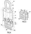
- FIGS. 4 and 5 A second, alternative embodiment of a secure sealing device 101 is illustrated in FIGS. 4 and 5 .
- the same reference numbers as for the components of the first embodiment are used for the analogous components of the second embodiment.
- This second embodiment differs from the first embodiment in that the second end 102b of the closure element 102 is solid with the locking body 103, with the electrically conductive path 120 fixedly connected to the second terminal 118.
- the locking core 112 thus only has a single holding mechanism, configured so as to hold the first end 102a of the closure element 102 when it is introduced in the channel 111 leading to the first terminal 117.
- this secure sealing device 101 works analogously to that of the first embodiment.
- the same power sweep technique may be used to determine a breach of this secure sealing device 101.
- FIGS. 6 and 7 A secure sealing device 101 according to a third embodiment of the present invention is illustrated in FIGS. 6 and 7 .
- the same reference numbers as for the components of the first and second embodiment are used for the analogous components of this third embodiment.
- This secure sealing device 101 is similar to that of the first embodiment, except in particular in that the electrically conductive path 120 of the closure element 102 is not sheathed, but exposed instead.
- the RFID inlay 104 does not present any electric terminals configured to contact this electrically conductive path 120, which instead contacts the metallic locking core 112 at both ends 102a, 102b of the closure element 102.
- any provision for the active detection and storage of a breach of the secure sealing device 101 by the RFID integrated circuit 105 is not limited to the length of the conductive path 120 is substantially equal to X times half a working wavelength of the radiofrequency transceiver, wherein X is a whole number equal to or higher than one, the closed loop formed by the intact conductive path 120 and the metallic locking core 112 can significantly increase the range of the radiofrequency transceiver. The corresponding decrease in this range in case of a breach of the secure sealing device 101 breaking the conductive path 120 can be detected by an RFID reader during remote inspection of the secure sealing device 101 using the abovementioned power sweep technique, alerting to such tampering.
- FIGS. 8A , 8B and 9 A secure sealing device 101 according to a fourth embodiment of the present invention is illustrated in FIGS. 8A , 8B and 9 .
- this secure sealing device 101 comprises a closure element 102 in the form of a plastic ratchet strap, and a locking body 103 integrally formed with the closure element 102.
- a first end 102a of this closure element 102a is free, whereas a second end 102b is fixedly connected to the locking body 103.
- the locking body 103 presents an opening 115 for receiving the first end 102a of the closure element 102 to close the secure sealing device 101.
- a holding mechanism 116 is shaped so as to allow the introduction of the closure element 102 through the opening 115 in one direction, but cooperate with the ratchet teeth 102c to prevent its subsequent retreat in the opposite direction.
- This holding mechanism can be reinforced to ensure that, under a pulling force, the closure element 102 will break before the irreversible connection between the lock body 103 and the first end 102a of the closure element 102.
- the lock body 103 forms a tag which can present visible markings (not shown), in the form, for instance, of alphanumeric codes, bar codes, or other human- or machine-readable codes, printed or embossed, or of other authentication or identification markings, such as, for instance, holograms.
- the secure sealing device 101 also comprises, embedded within the locking body 103, an RFID inlay 104 carrying an electric circuit comprising a data carrier, a transceiver, and first and second antennas 106,107 for the transceiver.
- the data carrier and transceiver are also integrated in a RFID integrated circuit 105, compliant with ISO/IEC 18000.
- the working frequencies of this RFID integrated circuit 105 may also be, for instance, 2.45 GHz, as specified under ISO/IEC 18000-4, 860-960 MHz, as specified under ISO/IEC 18000-6, and/or 433 MHz, as specified under ISO/IEC 18000-7.
- the RFID integrated circuit may be configured so as to use a plurality of different frequencies.
- the data carrier can be a read-only or a rewritable memory, wherein a rewritable memory could store information received by the radiofrequency transceiver, such as, for instance, itinerary information collected at each reading of the radiofrequency transceiver.
- the substrate of the RFID inlay 104 is also n-shaped, and the antennas 106,107 formed on two lateral segments 104b, 104c oriented following two parallel planes, each at a straight angle to the plane of the intermediate segment 104a.
- the secure sealing device 101 also comprises a plurality of parallel conductive paths 120 of different lengths in the closure element 102, printed on a non-conductive substrate of the secure sealing device 101.
- This non-conductive substrate can be produced, for instance, in a first injection molding step, and the RFID inlay 104 and plurality of parallel conductive paths 120 can be safely encapsulated in a subsequent second injection molding step.
- the length of each conductive path 120 can be substantially equal to one or several times half a working wavelength of the radiofrequency transceiver.
- the radiofrequency transceiver has a first working frequency in the 860-960 MHz band, and a second working frequency around 433 MHz, which correspond, respectively, to a first wavelength of approximately 0.35 m and a second wavelength of 122 mm
- the length of a first conductive path 120 can be substantially equal to X times 175 mm, and that of a second conductive path 120 substantially equal to Y times 61 mm, wherein both X and Y are whole numbers equal or higher than one.
- there is inductive coupling between the planar antennas 106, 107 and the corresponding electrically conductive path 120 enhancing the range of the radiofrequency transceiver.
- the elongated, flexible closure member 102 can be threaded and looped around two adjacent elements closing an access to a content to be sealed, such as, for instance, hasps attached to respective wings of a door of a shipping container.
- the second end 102b of the closure member 102 is then threaded through the opening 115, irreversibly connecting it to the locking body 103, and preventing the separation of the abovementioned two adjacent elements, so that access to the sealed content is effectively prevented unless the closure member 102 is broken.
- the conductive paths 120 are also broken, and the range of the radiofrequency transceiver decreased, as in the third embodiment. It must be noted that, because the electrically conductive path 120 is embedded within the closure member 102, it will normally not be possible to reliably re-establish this electrically conductive path 120 by repairing the broken closure member 102.
- the radiofrequency transceiver 105 is interrogated by a remote reader, the range at which it will be able to respond to an interrogation signal at a given transmission power will thus depend on the state of the closure member 102.
- the abovementioned power sweep technique may thus be used to determine whether a closer inspection of the secure sealing device 101 is appropriate.
- the visible markings in the locking body 103 can then complement the information provided by the radiofrequency transceiver 105.
- the closure member 102 takes the form of a locking pin with a first free end 102a, a second free end 102b, and a metal core forming an electrically conductive path 120.
- This electrically conductive path 120 is exposed at least at said first free end 102a, which presents a tapered edge 130 and an annular groove 131 on its outer perimeter, but an electrically insulating sheath 121 may at least partially cover the rest of the electrically conductive path 120.
- the closure element 102 has a round cross-section, although other cross-sections, for example polygonal cross-sections, can alternatively be considered. Its second free end 102b presents an enlarged cross-section.
- the locking body 103 comprises a tubular locking core 112 with a channel 111, closed at one end by an end cap 132, and open at the other end for insertion of the first free end 102a of the closure element 102.
- the end cap 132 presents a blind hole 136 opening into said channel 111.
- a snap ring 133 held within the locking core 112 of the locking body 103, between said end cap 132 and a metal ring 134, forms a holding mechanism for locking said first free end 102a of the closure member 102, following its insertion into channel 111, by snapping into the annular groove 131 around the first free end 102a of the closure element 102.
- the secure sealing device 101 also comprises, embedded within the locking body 103 and wrapped around its locking core 112, a flexible RFID inlay 104 carrying an electric circuit comprising a data carrier, a transceiver, an antenna 106 for the transceiver, and first and second electric terminals 117,118.
- This flexible RFID 104 is illustrated, flat and in more detail, in FIG. 11 .
- the data carrier and transceiver are also integrated in a RFID integrated circuit 105, compliant with ISO/IEC 18000.
- the working frequencies of this RFID integrated circuit 105 may also be, for instance, 2.45 GHz, as specified under ISO/IEC 18000-4, 860-960 MHz, as specified under ISO/IEC 18000-6, and/or 433 MHz, as specified under ISO/IEC 18000-7.
- the data carrier can be a read-only or a rewritable memory, wherein a rewritable memory could store information received by the radiofrequency transceiver, such as, for instance, itinerary information collected at each reading of the radiofrequency transceiver.
- Each one of the first and second electric terminals 117, 118 is directly connected to the RFID integrated circuit 105 over a conductive path printed onto the flexible substrate of the RFID inlay 104.
- the RFID inlay 104 is wrapped around the locking core 112, wherein the conductive paths leading to the first and second electric terminals 117,118 reach between the end cap 132 and the locking core 112 and into the blind hole 136 of the end cap 132, so that the first free end 102a of the closure element 102, when locked into the channel 111, contacts both these first and second electric terminals 117,118, establishing an electric connection between them.
- the RFID integrated circuit 105 in this embodiment may also be passive, that is, powered only by the energy of incoming radiofrequency signals, or it may be connected to a power source, such as a battery or capacitor, possibly contained within the secure sealing device 101.
- This RFID integrated circuit 105 is also configured so as to detect an electric connection between the two electric terminals 117, 118. If the RFID integrated circuit 105 has a rewritable memory and remains connected to a power source, it may also be configured to register, in the rewritable memory, the event of such an electric connection between the terminals 117, 118 and/or its interruption.
- the antenna 106 is a planar antenna formed also by a conductive path printed onto the flexible substrate of the RFID inlay 104, and comprises a first meandering segment 106a, and a second segment 106b formed as a single, broader electrically conductive strip, shaped so as to form a ring around the metal ring 134 within the locking core 112 when the RFID inlay 104 is wrapped around the locking core 112. This increases the inductive coupling between the antenna 106, the metal ring 134, and the electrically conductive path 120 within the closure member 102 when the first free end 102a of the closure member 102 is locked within the channel 111, enhancing the range of the radiofrequency transceiver.
- the length of this conductive path 120 can be substantially equal to X times half a working wavelength of the radiofrequency transceiver, wherein X is a whole number equal to or higher than one, so as to enhance the range of the radiofrequency transceiver by inductive coupling.
- a shorter length namely a length of 1/2 x times the working wavelength of the radiofrequency transceiver, is also conducive to inductive coupling leading to a marked improvement in the range of the radiofrequency transceiver.
- the length of the conductive path 120 can be substantially equal to 87.5 mm, that is, one-half half said wavelength, or even 43.75 mm, that is, one-quarter half said wavelength, and show a marked improvement in the range of the radiofrequency transceiver.
- Such fractional lengths are also potentially applicable to the previous embodiments.
- an outer shell 135 of a dielectric material such as for instance a thermosetting or thermoplastic polymer material, surrounds the RFID inlay 104 and the locking core 112, leaving just an opening 115 into the channel 111.
- the locking body 103 can present visible markings (not shown), in the form, for instance, of alphanumeric codes, bar codes, or other human- or machine-readable codes, printed or embossed, or of other authentication or identification markings, such as, for instance, holograms.
- closure member 102 can be threaded through two adjacent elements closing an access to a content to be sealed, such as, for instance, hasps attached to respective wings of a door of a shipping container.
- the secure sealing device 101 is closed by inserting the first free end 102a of the closure element 102, through the opening 115, into the locking body 103, where it is locked by the holding mechanism within the locking core 112, irreversibly connecting said first end 102a of the closure element 102 to the locking body 103, to prevent the separation of the abovementioned two adjacent elements, so that access to the sealed content is effectively prevented unless the closure element 102 is broken.
- the exposed electrically conductive path 120 connects the two electric terminals 117, 118. Once the electric contacts are made, the electric circuit is closed between the two electric terminals 117, 118. If the closure element 102 is pulled by force from the locking body, the RFID integrated circuit 105 will detect this seal breach as an interruption of the connection between the terminals 117, 118. If the RFID integrated circuit 105 is an active circuit with a rewriteable memory, it may even register this event, so as to reveal the breach even if the terminals 117, 118 are subsequently reconnected.
- the RFID integrated circuit 105 and antenna 106 can be configured so as to communicate with readers at several meters' distance, further enhanced by the inductive coupling between the antenna 106, the metal ring 134, and the conductive path 120.
- the remote inspection of the seals can therefore proceed in an analogous manner as for the previous embodiments.
- the abovementioned power sweep technique can also be used for this fifth embodiment.
Landscapes
- Engineering & Computer Science (AREA)
- General Physics & Mathematics (AREA)
- Physics & Mathematics (AREA)
- Theoretical Computer Science (AREA)
- Computer Security & Cryptography (AREA)
- Microelectronics & Electronic Packaging (AREA)
- Computer Hardware Design (AREA)
- Business, Economics & Management (AREA)
- Emergency Management (AREA)
- Lock And Its Accessories (AREA)
- Burglar Alarm Systems (AREA)
- Package Closures (AREA)
- Details Of Aerials (AREA)
- Near-Field Transmission Systems (AREA)
Claims (15)
- Dispositif de scellement sécurisé (101) comprenant au moins :un élément de fermeture (102) avec au moins une piste électriquement conductrice (120) ;un corps de verrouillage (103) comprenant un circuit électrique avec un support de données et un émetteur-récepteur à radiofréquence avec une longueur d'onde de travail prédéterminée, ledit corps de verrouillage (103) étant configuré pour être verrouillé au niveau d'au moins une extrémité libre (102a) dudit élément de fermeture (102) afin de fixer le corps de verrouillage (103) sur un objet à sceller ; etle dispositif de scellement sécurisé (101) étant caractérisé en ce que ladite au moins une piste électriquement conductrice (120) de l'élément de fermeture (102) a une longueur qui est sensiblement égale à X ou 1/2X fois la moitié de ladite longueur d'onde de travail prédéterminée de l'émetteur-récepteur à radiofréquence, où X est un nombre entier égal ou supérieur à un.
- Dispositif de scellement sécurisé (101) selon la revendication 1, dans lequel ledit corps de verrouillage (102a, 102b) est configuré pour verrouiller ensemble une première et une seconde extrémité (102a, 102b) dudit élément de fermeture (102) afin de fixer le corps de verrouillage sur l'objet à sceller.
- Dispositif de scellement sécurisé (101) selon la revendication 2, dans lequel ledit circuit électrique comprend en outre au moins une première antenne plane (106) orientée dans un premier plan et raccordée audit émetteur-récepteur à radiofréquence, et dans lequel ledit corps de verrouillage (103) est configuré pour verrouiller ensemble lesdites première et seconde extrémités (102a, 102b) de l'élément de fermeture orienté dans un plan sensiblement parallèle audit premier plan.
- Dispositif de scellement sécurisé (101) selon la revendication 3, dans lequel ledit circuit électrique comprend en outre au moins une seconde antenne plane (107) orientée sensiblement parallèlement à la première antenne plane (106).
- Dispositif de scellement sécurisé (101) selon l'une quelconque des revendications 2 à 4, dans lequel ledit circuit électrique comprend des première et seconde bornes électriques (117, 118) configurées pour être raccordées à la piste électriquement conductrice (120) de l'élément de fermeture (102) lorsque les première et seconde extrémités (102a, 102b) de l'élément de fermeture (102) sont verrouillées ensemble par le corps de verrouillage (103).
- Dispositif de scellement sécurisé (101) selon la revendication 5, dans lequel le circuit électrique est configuré pour stocker automatiquement dans ledit support de données si une connexion entre lesdites première et seconde bornes électriques (117, 118) a été interrompue.
- Dispositif de scellement sécurisé (101) selon l'une quelconque des revendications 5 ou 6, dans lequel le circuit électrique est formé sur un substrat comprenant au moins un premier segment, incorporant au moins une première antenne plane (106) de l'émetteur-récepteur à radiofréquence, s'étendant dans un premier plan et un deuxième segment, supportant au moins lesdites première et seconde bornes (117, 118) et s'étendant dans un second plan à un angle, par exemple un angle sensiblement droit, par rapport au premier plan.
- Dispositif de scellement sécurisé (101) selon la revendication 7, dans lequel ledit substrat comprend en outre un troisième segment, supportant au moins une seconde antenne plane (107) de l'émetteur-récepteur à radiofréquence, et s'étendant sensiblement parallèlement au premier segment.
- Dispositif de scellement sécurisé (101) selon l'une quelconque des revendications 1 à 8, dans lequel ledit circuit électrique est enfermé à l'intérieur d'un matériau diélectrique.
- Dispositif de scellement sécurisé (101) selon l'une quelconque des revendications précédentes, dans lequel ledit corps de verrouillage (103) comprend au moins une première ouverture (115) pour l'insertion d'une première extrémité libre (102a) dudit élément de fermeture dans ledit corps de verrouillage (103), et un premier mécanisme de maintien pour empêcher le retrait de ladite première extrémité libre (102a) de ladite première ouverture (115) une fois insérée.
- Dispositif de scellement sécurisé (101) selon la revendication 10, dans lequel ledit corps de verrouillage (103) comprend une seconde ouverture (115) pour l'insertion d'une seconde extrémité libre (102b) dudit élément de fermeture (102) dans ledit corps de verrouillage (103), et un second mécanisme de maintien pour empêcher le retrait de ladite seconde extrémité libre (102b) de ladite seconde ouverture (115) une fois insérée.
- Dispositif de scellement sécurisé (101) selon la revendication 10, dans lequel une seconde extrémité (102b) dudit élément de fermeture (102) est solidaire avec ledit corps de verrouillage (103).
- Dispositif de scellement sécurisé (101) selon l'une quelconque des revendications précédentes, dans lequel l'élément de fermeture (102) est flexible.
- Dispositif de scellement sécurisé (101) selon l'une quelconque des revendications 1 à 13, dans lequel ledit émetteur-récepteur à radiofréquence a une pluralité de longueurs d'onde de travail prédéterminées, et ledit élément de fermeture (102) a une pluralité de pistes électriquement conductrices (120) à différentes longueurs, chacune sensiblement égale à un multiple d'une moitié de l'une de ladite pluralité de longueurs d'onde de travail prédéterminées de l'émetteur-récepteur à radiofréquence.
- Procédé pour vérifier un dispositif de scellement sécurisé (101) selon l'une quelconque des revendications 1 à 14, dans lequel un lecteur externe, positionné à une plage prédéterminée dudit émetteur-récepteur à radiofréquence, envoie un signal d'interrogation, adressé à l'émetteur-récepteur à radiofréquence et en utilisant ladite longueur d'onde de travail, à différents niveaux de puissance de transmission, et délivre une alerte s'il n'arrive pas à recevoir une réponse de l'émetteur-récepteur à radiofréquence sous un seuil de puissance de transmission prédéterminée du signal d'interrogation.
Priority Applications (2)
| Application Number | Priority Date | Filing Date | Title |
|---|---|---|---|
| EP15188836.9A EP2991002A1 (fr) | 2012-12-17 | 2013-12-17 | Dispositif d'étanchéité sécurisé et procédé |
| EP13864760.7A EP2915158B1 (fr) | 2012-12-17 | 2013-12-17 | Dispositif et procédé d'étanchéité sécurisé |
Applications Claiming Priority (3)
| Application Number | Priority Date | Filing Date | Title |
|---|---|---|---|
| EP12197521.3A EP2743864A1 (fr) | 2012-12-17 | 2012-12-17 | Dispositif d'étanchéité sécurisé et procédé |
| PCT/IB2013/002787 WO2014096928A1 (fr) | 2012-12-17 | 2013-12-17 | Dispositif et procédé d'étanchéité sécurisé |
| EP13864760.7A EP2915158B1 (fr) | 2012-12-17 | 2013-12-17 | Dispositif et procédé d'étanchéité sécurisé |
Related Child Applications (2)
| Application Number | Title | Priority Date | Filing Date |
|---|---|---|---|
| EP15188836.9A Division EP2991002A1 (fr) | 2012-12-17 | 2013-12-17 | Dispositif d'étanchéité sécurisé et procédé |
| EP15188836.9A Division-Into EP2991002A1 (fr) | 2012-12-17 | 2013-12-17 | Dispositif d'étanchéité sécurisé et procédé |
Publications (3)
| Publication Number | Publication Date |
|---|---|
| EP2915158A1 EP2915158A1 (fr) | 2015-09-09 |
| EP2915158A4 EP2915158A4 (fr) | 2015-12-02 |
| EP2915158B1 true EP2915158B1 (fr) | 2016-05-25 |
Family
ID=47559139
Family Applications (3)
| Application Number | Title | Priority Date | Filing Date |
|---|---|---|---|
| EP12197521.3A Withdrawn EP2743864A1 (fr) | 2012-12-17 | 2012-12-17 | Dispositif d'étanchéité sécurisé et procédé |
| EP13864760.7A Active EP2915158B1 (fr) | 2012-12-17 | 2013-12-17 | Dispositif et procédé d'étanchéité sécurisé |
| EP15188836.9A Withdrawn EP2991002A1 (fr) | 2012-12-17 | 2013-12-17 | Dispositif d'étanchéité sécurisé et procédé |
Family Applications Before (1)
| Application Number | Title | Priority Date | Filing Date |
|---|---|---|---|
| EP12197521.3A Withdrawn EP2743864A1 (fr) | 2012-12-17 | 2012-12-17 | Dispositif d'étanchéité sécurisé et procédé |
Family Applications After (1)
| Application Number | Title | Priority Date | Filing Date |
|---|---|---|---|
| EP15188836.9A Withdrawn EP2991002A1 (fr) | 2012-12-17 | 2013-12-17 | Dispositif d'étanchéité sécurisé et procédé |
Country Status (6)
| Country | Link |
|---|---|
| US (1) | US9745782B2 (fr) |
| EP (3) | EP2743864A1 (fr) |
| CN (1) | CN105190730B (fr) |
| BR (1) | BR112015014236B1 (fr) |
| DK (1) | DK2915158T3 (fr) |
| WO (1) | WO2014096928A1 (fr) |
Cited By (2)
| Publication number | Priority date | Publication date | Assignee | Title |
|---|---|---|---|---|
| DE102016010916A1 (de) | 2016-09-08 | 2018-03-08 | Giesecke+Devrient Mobile Security Gmbh | Sicherheitssiegel |
| DE102020203970A1 (de) | 2020-03-26 | 2021-09-30 | Fraunhofer-Gesellschaft zur Förderung der angewandten Forschung eingetragener Verein | Hochfrequenzanordnung mit einer vorderseitigen und einer rückseitigen Antenne |
Families Citing this family (19)
| Publication number | Priority date | Publication date | Assignee | Title |
|---|---|---|---|---|
| CN104269103B (zh) * | 2014-10-16 | 2017-08-11 | 广西华瑞电气有限公司 | 封印装置 |
| EP3057081B1 (fr) * | 2015-02-13 | 2018-10-31 | Confidex Oy | Verrouillage de sécurité |
| US10044710B2 (en) | 2016-02-22 | 2018-08-07 | Bpip Limited Liability Company | Device and method for validating a user using an intelligent voice print |
| ITUA20162059A1 (it) * | 2016-03-07 | 2017-09-07 | Luciano Grapsa | Sigillo di sicurezza autobloccante |
| FR3050877B1 (fr) * | 2016-04-28 | 2018-06-01 | Safran Helicopter Engines | Dispositif de radio-identification pour composant de moteur d'aeronef |
| ITUA20163129A1 (it) * | 2016-05-04 | 2017-11-04 | Guidi Francesco Srlu | Dispositivo indossabile con chipset rfid o nfc integrato |
| WO2018091053A1 (fr) * | 2016-11-15 | 2018-05-24 | Lyngsoe Systems Ltd | Joint de câble électronique |
| IT201700047094A1 (it) * | 2017-05-02 | 2018-11-02 | Leonardo Sistemi Integrati S R L | Sistema di sigillatura anti effrazione |
| WO2019051549A1 (fr) * | 2017-09-15 | 2019-03-21 | Senver Holdings Pty Ltd | Dispositifs formant minuterie |
| EP3486889A1 (fr) * | 2017-11-16 | 2019-05-22 | Assa Abloy AB | Dispositif d'étanchéité |
| EP3493170B1 (fr) * | 2017-12-02 | 2021-07-07 | The Boeing Company | Dispositif d'inviolabilité sans fil |
| CA3101005A1 (fr) | 2018-06-01 | 2019-12-05 | Stress Engineering Services, Inc. | Systemes et procedes de logistique de surveillance, de suivi et de retracage |
| US11322005B2 (en) * | 2018-06-10 | 2022-05-03 | Hangzhou Timing Security Technologies Co., Ltd. | Portions of a security device system; methods of making and using them |
| CN111354113B (zh) * | 2018-12-20 | 2024-12-27 | 夏敬懿 | 锁封装置 |
| CN111353570B (zh) * | 2018-12-20 | 2021-06-18 | 夏敬懿 | 电子封签 |
| TWI750547B (zh) * | 2019-12-03 | 2021-12-21 | 國家中山科學研究院 | 近場通訊電子插銷結構 |
| WO2023158624A2 (fr) * | 2022-02-15 | 2023-08-24 | Stress Engineering Services, Inc. | Systèmes et procédés pour faciliter la logistique |
| US12482337B2 (en) * | 2023-05-04 | 2025-11-25 | Shenzhen Wins Electronic Technology Co., Ltd. | Method for assembling an RFID component to a locator in a cable lock |
| CN117248793A (zh) * | 2023-10-11 | 2023-12-19 | 深圳市双盈电子科技有限公司 | 一种提高钢丝锁抗拉强度的方法及钢丝锁 |
Family Cites Families (15)
| Publication number | Priority date | Publication date | Assignee | Title |
|---|---|---|---|---|
| US6265973B1 (en) | 1999-04-16 | 2001-07-24 | Transguard Industries, Inc. | Electronic security seal |
| US7239238B2 (en) | 2004-03-30 | 2007-07-03 | E. J. Brooks Company | Electronic security seal |
| US7202788B2 (en) | 2004-10-21 | 2007-04-10 | Yeng-Bao Shieh | RFID electronic seal and system using the RFID electronic seal |
| ES2617675T3 (es) | 2004-10-28 | 2017-06-19 | Assa Abloy Ab | Dispositivo de sellado de seguridad que comprende una etiqueta RFID |
| DE102004063487A1 (de) * | 2004-12-23 | 2006-07-13 | Intec Holding Gmbh | Siegeleinrichtung |
| TWM283040U (en) | 2004-12-24 | 2005-12-11 | Pretide Holdings Inc | RFID security seal |
| US7400247B2 (en) | 2005-11-04 | 2008-07-15 | Motorola, Inc. | Asset seal device and method |
| CN201142170Y (zh) * | 2007-09-24 | 2008-10-29 | 艾生有限公司 | 电子封条 |
| JP2009280273A (ja) | 2008-05-26 | 2009-12-03 | Fujitsu Ltd | 収納容器 |
| EP2189964A1 (fr) | 2008-11-21 | 2010-05-26 | The European Community, represented by the European Commission | Dispositif d'obturation |
| US8564410B2 (en) * | 2010-05-20 | 2013-10-22 | Paul Llewellyn Greene | Shipping container security process |
| CN102856635B (zh) | 2011-06-27 | 2016-05-04 | 光宝电子(广州)有限公司 | 多频天线及具有该多频天线的电子装置 |
| WO2013142104A1 (fr) * | 2012-03-19 | 2013-09-26 | Neology Inc. | Serrure à pêne de scellage inviolable pour conteneur de marchandises |
| EP2891111A1 (fr) * | 2012-08-28 | 2015-07-08 | Tagsys SAS | Dispositif d'identification d'objet par étiquette rfid de petite taille |
| EP2717242A1 (fr) * | 2012-10-03 | 2014-04-09 | Oneseal A/S | Verrouillage par enclenchement pour un conteneur |
-
2012
- 2012-12-17 EP EP12197521.3A patent/EP2743864A1/fr not_active Withdrawn
-
2013
- 2013-12-17 DK DK13864760.7T patent/DK2915158T3/en active
- 2013-12-17 BR BR112015014236-2A patent/BR112015014236B1/pt active IP Right Grant
- 2013-12-17 EP EP13864760.7A patent/EP2915158B1/fr active Active
- 2013-12-17 US US14/652,796 patent/US9745782B2/en active Active
- 2013-12-17 EP EP15188836.9A patent/EP2991002A1/fr not_active Withdrawn
- 2013-12-17 CN CN201380072989.0A patent/CN105190730B/zh active Active
- 2013-12-17 WO PCT/IB2013/002787 patent/WO2014096928A1/fr not_active Ceased
Non-Patent Citations (1)
| Title |
|---|
| None * |
Cited By (2)
| Publication number | Priority date | Publication date | Assignee | Title |
|---|---|---|---|---|
| DE102016010916A1 (de) | 2016-09-08 | 2018-03-08 | Giesecke+Devrient Mobile Security Gmbh | Sicherheitssiegel |
| DE102020203970A1 (de) | 2020-03-26 | 2021-09-30 | Fraunhofer-Gesellschaft zur Förderung der angewandten Forschung eingetragener Verein | Hochfrequenzanordnung mit einer vorderseitigen und einer rückseitigen Antenne |
Also Published As
| Publication number | Publication date |
|---|---|
| EP2991002A1 (fr) | 2016-03-02 |
| US20150337564A1 (en) | 2015-11-26 |
| BR112015014236A2 (pt) | 2017-07-11 |
| WO2014096928A1 (fr) | 2014-06-26 |
| CN105190730B (zh) | 2018-08-07 |
| US9745782B2 (en) | 2017-08-29 |
| CN105190730A (zh) | 2015-12-23 |
| EP2915158A1 (fr) | 2015-09-09 |
| BR112015014236B1 (pt) | 2020-12-01 |
| DK2915158T3 (en) | 2016-08-29 |
| EP2915158A4 (fr) | 2015-12-02 |
| EP2743864A1 (fr) | 2014-06-18 |
Similar Documents
| Publication | Publication Date | Title |
|---|---|---|
| EP2915158B1 (fr) | Dispositif et procédé d'étanchéité sécurisé | |
| US10689882B2 (en) | Tamper evident cargo container seal bolt lock | |
| US20200105167A1 (en) | Reusable bolt electronic seal module with gps/cellular phone communications & tracking system | |
| EP2823118B1 (fr) | Serrure à pêne de fermeture inviolable pour conteneur de chargement | |
| US7239238B2 (en) | Electronic security seal | |
| EP2590154A1 (fr) | Sceau de sécurité | |
| EP2991061B1 (fr) | Élément d'attache à circuit identificateur intégré | |
| WO2009098670A2 (fr) | Joint inviolable | |
| CN114375469A (zh) | 显窃启密封件 | |
| WO2018091053A1 (fr) | Joint de câble électronique | |
| EP2394252A1 (fr) | Dispositif et système pour l'intégrité d'un conteneur d'expédition |
Legal Events
| Date | Code | Title | Description |
|---|---|---|---|
| PUAI | Public reference made under article 153(3) epc to a published international application that has entered the european phase |
Free format text: ORIGINAL CODE: 0009012 |
|
| 17P | Request for examination filed |
Effective date: 20150605 |
|
| AK | Designated contracting states |
Kind code of ref document: A1 Designated state(s): AL AT BE BG CH CY CZ DE DK EE ES FI FR GB GR HR HU IE IS IT LI LT LU LV MC MK MT NL NO PL PT RO RS SE SI SK SM TR |
|
| AX | Request for extension of the european patent |
Extension state: BA ME |
|
| DAX | Request for extension of the european patent (deleted) | ||
| RA4 | Supplementary search report drawn up and despatched (corrected) |
Effective date: 20151029 |
|
| RIC1 | Information provided on ipc code assigned before grant |
Ipc: G09F 3/03 20060101ALI20151023BHEP Ipc: G06K 19/077 20060101AFI20151023BHEP |
|
| REG | Reference to a national code |
Ref country code: DE Ref legal event code: R079 Ref document number: 602013008130 Country of ref document: DE Free format text: PREVIOUS MAIN CLASS: G09F0003030000 Ipc: G06K0019077000 |
|
| GRAP | Despatch of communication of intention to grant a patent |
Free format text: ORIGINAL CODE: EPIDOSNIGR1 |
|
| RIC1 | Information provided on ipc code assigned before grant |
Ipc: G08B 21/18 20060101ALI20160224BHEP Ipc: G09F 3/03 20060101ALI20160224BHEP Ipc: G06K 19/077 20060101AFI20160224BHEP Ipc: G06F 3/03 20060101ALI20160224BHEP |
|
| INTG | Intention to grant announced |
Effective date: 20160308 |
|
| GRAS | Grant fee paid |
Free format text: ORIGINAL CODE: EPIDOSNIGR3 |
|
| GRAA | (expected) grant |
Free format text: ORIGINAL CODE: 0009210 |
|
| AK | Designated contracting states |
Kind code of ref document: B1 Designated state(s): AL AT BE BG CH CY CZ DE DK EE ES FI FR GB GR HR HU IE IS IT LI LT LU LV MC MK MT NL NO PL PT RO RS SE SI SK SM TR |
|
| REG | Reference to a national code |
Ref country code: GB Ref legal event code: FG4D |
|
| REG | Reference to a national code |
Ref country code: CH Ref legal event code: EP |
|
| REG | Reference to a national code |
Ref country code: IE Ref legal event code: FG4D Ref country code: AT Ref legal event code: REF Ref document number: 802867 Country of ref document: AT Kind code of ref document: T Effective date: 20160615 |
|
| REG | Reference to a national code |
Ref country code: DE Ref legal event code: R096 Ref document number: 602013008130 Country of ref document: DE |
|
| REG | Reference to a national code |
Ref country code: DK Ref legal event code: T3 Effective date: 20160825 |
|
| REG | Reference to a national code |
Ref country code: LT Ref legal event code: MG4D |
|
| REG | Reference to a national code |
Ref country code: NL Ref legal event code: MP Effective date: 20160525 |
|
| REG | Reference to a national code |
Ref country code: FR Ref legal event code: PLFP Year of fee payment: 4 |
|
| PG25 | Lapsed in a contracting state [announced via postgrant information from national office to epo] |
Ref country code: LT Free format text: LAPSE BECAUSE OF FAILURE TO SUBMIT A TRANSLATION OF THE DESCRIPTION OR TO PAY THE FEE WITHIN THE PRESCRIBED TIME-LIMIT Effective date: 20160525 Ref country code: FI Free format text: LAPSE BECAUSE OF FAILURE TO SUBMIT A TRANSLATION OF THE DESCRIPTION OR TO PAY THE FEE WITHIN THE PRESCRIBED TIME-LIMIT Effective date: 20160525 Ref country code: NL Free format text: LAPSE BECAUSE OF FAILURE TO SUBMIT A TRANSLATION OF THE DESCRIPTION OR TO PAY THE FEE WITHIN THE PRESCRIBED TIME-LIMIT Effective date: 20160525 Ref country code: NO Free format text: LAPSE BECAUSE OF FAILURE TO SUBMIT A TRANSLATION OF THE DESCRIPTION OR TO PAY THE FEE WITHIN THE PRESCRIBED TIME-LIMIT Effective date: 20160825 |
|
| REG | Reference to a national code |
Ref country code: AT Ref legal event code: MK05 Ref document number: 802867 Country of ref document: AT Kind code of ref document: T Effective date: 20160525 |
|
| PG25 | Lapsed in a contracting state [announced via postgrant information from national office to epo] |
Ref country code: RS Free format text: LAPSE BECAUSE OF FAILURE TO SUBMIT A TRANSLATION OF THE DESCRIPTION OR TO PAY THE FEE WITHIN THE PRESCRIBED TIME-LIMIT Effective date: 20160525 Ref country code: ES Free format text: LAPSE BECAUSE OF FAILURE TO SUBMIT A TRANSLATION OF THE DESCRIPTION OR TO PAY THE FEE WITHIN THE PRESCRIBED TIME-LIMIT Effective date: 20160525 Ref country code: SE Free format text: LAPSE BECAUSE OF FAILURE TO SUBMIT A TRANSLATION OF THE DESCRIPTION OR TO PAY THE FEE WITHIN THE PRESCRIBED TIME-LIMIT Effective date: 20160525 Ref country code: PT Free format text: LAPSE BECAUSE OF FAILURE TO SUBMIT A TRANSLATION OF THE DESCRIPTION OR TO PAY THE FEE WITHIN THE PRESCRIBED TIME-LIMIT Effective date: 20160926 Ref country code: GR Free format text: LAPSE BECAUSE OF FAILURE TO SUBMIT A TRANSLATION OF THE DESCRIPTION OR TO PAY THE FEE WITHIN THE PRESCRIBED TIME-LIMIT Effective date: 20160826 Ref country code: LV Free format text: LAPSE BECAUSE OF FAILURE TO SUBMIT A TRANSLATION OF THE DESCRIPTION OR TO PAY THE FEE WITHIN THE PRESCRIBED TIME-LIMIT Effective date: 20160525 |
|
| PG25 | Lapsed in a contracting state [announced via postgrant information from national office to epo] |
Ref country code: RO Free format text: LAPSE BECAUSE OF FAILURE TO SUBMIT A TRANSLATION OF THE DESCRIPTION OR TO PAY THE FEE WITHIN THE PRESCRIBED TIME-LIMIT Effective date: 20160525 Ref country code: SK Free format text: LAPSE BECAUSE OF FAILURE TO SUBMIT A TRANSLATION OF THE DESCRIPTION OR TO PAY THE FEE WITHIN THE PRESCRIBED TIME-LIMIT Effective date: 20160525 Ref country code: EE Free format text: LAPSE BECAUSE OF FAILURE TO SUBMIT A TRANSLATION OF THE DESCRIPTION OR TO PAY THE FEE WITHIN THE PRESCRIBED TIME-LIMIT Effective date: 20160525 Ref country code: CZ Free format text: LAPSE BECAUSE OF FAILURE TO SUBMIT A TRANSLATION OF THE DESCRIPTION OR TO PAY THE FEE WITHIN THE PRESCRIBED TIME-LIMIT Effective date: 20160525 |
|
| PG25 | Lapsed in a contracting state [announced via postgrant information from national office to epo] |
Ref country code: BE Free format text: LAPSE BECAUSE OF FAILURE TO SUBMIT A TRANSLATION OF THE DESCRIPTION OR TO PAY THE FEE WITHIN THE PRESCRIBED TIME-LIMIT Effective date: 20160525 Ref country code: PL Free format text: LAPSE BECAUSE OF FAILURE TO SUBMIT A TRANSLATION OF THE DESCRIPTION OR TO PAY THE FEE WITHIN THE PRESCRIBED TIME-LIMIT Effective date: 20160525 Ref country code: SM Free format text: LAPSE BECAUSE OF FAILURE TO SUBMIT A TRANSLATION OF THE DESCRIPTION OR TO PAY THE FEE WITHIN THE PRESCRIBED TIME-LIMIT Effective date: 20160525 Ref country code: AT Free format text: LAPSE BECAUSE OF FAILURE TO SUBMIT A TRANSLATION OF THE DESCRIPTION OR TO PAY THE FEE WITHIN THE PRESCRIBED TIME-LIMIT Effective date: 20160525 |
|
| REG | Reference to a national code |
Ref country code: DE Ref legal event code: R097 Ref document number: 602013008130 Country of ref document: DE |
|
| PLBE | No opposition filed within time limit |
Free format text: ORIGINAL CODE: 0009261 |
|
| STAA | Information on the status of an ep patent application or granted ep patent |
Free format text: STATUS: NO OPPOSITION FILED WITHIN TIME LIMIT |
|
| 26N | No opposition filed |
Effective date: 20170228 |
|
| PG25 | Lapsed in a contracting state [announced via postgrant information from national office to epo] |
Ref country code: SI Free format text: LAPSE BECAUSE OF FAILURE TO SUBMIT A TRANSLATION OF THE DESCRIPTION OR TO PAY THE FEE WITHIN THE PRESCRIBED TIME-LIMIT Effective date: 20160525 |
|
| REG | Reference to a national code |
Ref country code: CH Ref legal event code: PL |
|
| PG25 | Lapsed in a contracting state [announced via postgrant information from national office to epo] |
Ref country code: MC Free format text: LAPSE BECAUSE OF FAILURE TO SUBMIT A TRANSLATION OF THE DESCRIPTION OR TO PAY THE FEE WITHIN THE PRESCRIBED TIME-LIMIT Effective date: 20160525 |
|
| REG | Reference to a national code |
Ref country code: IE Ref legal event code: MM4A |
|
| REG | Reference to a national code |
Ref country code: FR Ref legal event code: PLFP Year of fee payment: 5 |
|
| PG25 | Lapsed in a contracting state [announced via postgrant information from national office to epo] |
Ref country code: CH Free format text: LAPSE BECAUSE OF NON-PAYMENT OF DUE FEES Effective date: 20161231 Ref country code: LI Free format text: LAPSE BECAUSE OF NON-PAYMENT OF DUE FEES Effective date: 20161231 Ref country code: LU Free format text: LAPSE BECAUSE OF NON-PAYMENT OF DUE FEES Effective date: 20161217 |
|
| PG25 | Lapsed in a contracting state [announced via postgrant information from national office to epo] |
Ref country code: IE Free format text: LAPSE BECAUSE OF NON-PAYMENT OF DUE FEES Effective date: 20161217 |
|
| PG25 | Lapsed in a contracting state [announced via postgrant information from national office to epo] |
Ref country code: HU Free format text: LAPSE BECAUSE OF FAILURE TO SUBMIT A TRANSLATION OF THE DESCRIPTION OR TO PAY THE FEE WITHIN THE PRESCRIBED TIME-LIMIT; INVALID AB INITIO Effective date: 20131217 |
|
| PG25 | Lapsed in a contracting state [announced via postgrant information from national office to epo] |
Ref country code: IS Free format text: LAPSE BECAUSE OF FAILURE TO SUBMIT A TRANSLATION OF THE DESCRIPTION OR TO PAY THE FEE WITHIN THE PRESCRIBED TIME-LIMIT Effective date: 20160525 Ref country code: HR Free format text: LAPSE BECAUSE OF FAILURE TO SUBMIT A TRANSLATION OF THE DESCRIPTION OR TO PAY THE FEE WITHIN THE PRESCRIBED TIME-LIMIT Effective date: 20160525 Ref country code: CY Free format text: LAPSE BECAUSE OF FAILURE TO SUBMIT A TRANSLATION OF THE DESCRIPTION OR TO PAY THE FEE WITHIN THE PRESCRIBED TIME-LIMIT Effective date: 20160525 Ref country code: MK Free format text: LAPSE BECAUSE OF FAILURE TO SUBMIT A TRANSLATION OF THE DESCRIPTION OR TO PAY THE FEE WITHIN THE PRESCRIBED TIME-LIMIT Effective date: 20160525 |
|
| PG25 | Lapsed in a contracting state [announced via postgrant information from national office to epo] |
Ref country code: BG Free format text: LAPSE BECAUSE OF FAILURE TO SUBMIT A TRANSLATION OF THE DESCRIPTION OR TO PAY THE FEE WITHIN THE PRESCRIBED TIME-LIMIT Effective date: 20160525 |
|
| PG25 | Lapsed in a contracting state [announced via postgrant information from national office to epo] |
Ref country code: MT Free format text: LAPSE BECAUSE OF NON-PAYMENT OF DUE FEES Effective date: 20161217 |
|
| PG25 | Lapsed in a contracting state [announced via postgrant information from national office to epo] |
Ref country code: AL Free format text: LAPSE BECAUSE OF FAILURE TO SUBMIT A TRANSLATION OF THE DESCRIPTION OR TO PAY THE FEE WITHIN THE PRESCRIBED TIME-LIMIT Effective date: 20160525 Ref country code: TR Free format text: LAPSE BECAUSE OF FAILURE TO SUBMIT A TRANSLATION OF THE DESCRIPTION OR TO PAY THE FEE WITHIN THE PRESCRIBED TIME-LIMIT Effective date: 20160525 |
|
| PGFP | Annual fee paid to national office [announced via postgrant information from national office to epo] |
Ref country code: IT Payment date: 20201214 Year of fee payment: 8 |
|
| PG25 | Lapsed in a contracting state [announced via postgrant information from national office to epo] |
Ref country code: IT Free format text: LAPSE BECAUSE OF NON-PAYMENT OF DUE FEES Effective date: 20211217 |
|
| REG | Reference to a national code |
Ref country code: DE Ref legal event code: R082 Ref document number: 602013008130 Country of ref document: DE Representative=s name: CBDL PATENTANWAELTE GBR, DE Ref country code: DE Ref legal event code: R082 Ref document number: 602013008130 Country of ref document: DE Representative=s name: CBDL PATENTANWAELTE EGBR, DE |
|
| P01 | Opt-out of the competence of the unified patent court (upc) registered |
Effective date: 20230609 |
|
| PGFP | Annual fee paid to national office [announced via postgrant information from national office to epo] |
Ref country code: GB Payment date: 20241219 Year of fee payment: 12 |
|
| PGFP | Annual fee paid to national office [announced via postgrant information from national office to epo] |
Ref country code: FR Payment date: 20241216 Year of fee payment: 12 |
|
| PGFP | Annual fee paid to national office [announced via postgrant information from national office to epo] |
Ref country code: DK Payment date: 20251230 Year of fee payment: 13 |
|
| PGFP | Annual fee paid to national office [announced via postgrant information from national office to epo] |
Ref country code: DE Payment date: 20251231 Year of fee payment: 13 |