EP2915224B1 - Dispositif rotatif d'interconnexion électrique - Google Patents
Dispositif rotatif d'interconnexion électrique Download PDFInfo
- Publication number
- EP2915224B1 EP2915224B1 EP13850584.7A EP13850584A EP2915224B1 EP 2915224 B1 EP2915224 B1 EP 2915224B1 EP 13850584 A EP13850584 A EP 13850584A EP 2915224 B1 EP2915224 B1 EP 2915224B1
- Authority
- EP
- European Patent Office
- Prior art keywords
- stator
- slip ring
- rotor assembly
- rotary device
- rotor
- Prior art date
- Legal status (The legal status is an assumption and is not a legal conclusion. Google has not performed a legal analysis and makes no representation as to the accuracy of the status listed.)
- Active
Links
Images





Classifications
-
- H—ELECTRICITY
- H01—ELECTRIC ELEMENTS
- H01R—ELECTRICALLY-CONDUCTIVE CONNECTIONS; STRUCTURAL ASSOCIATIONS OF A PLURALITY OF MUTUALLY-INSULATED ELECTRICAL CONNECTING ELEMENTS; COUPLING DEVICES; CURRENT COLLECTORS
- H01R39/00—Rotary current collectors, distributors or interrupters
- H01R39/64—Devices for uninterrupted current collection
-
- A—HUMAN NECESSITIES
- A61—MEDICAL OR VETERINARY SCIENCE; HYGIENE
- A61N—ELECTROTHERAPY; MAGNETOTHERAPY; RADIATION THERAPY; ULTRASOUND THERAPY
- A61N1/00—Electrotherapy; Circuits therefor
- A61N1/18—Applying electric currents by contact electrodes
- A61N1/32—Applying electric currents by contact electrodes alternating or intermittent currents
- A61N1/36—Applying electric currents by contact electrodes alternating or intermittent currents for stimulation
- A61N1/372—Arrangements in connection with the implantation of stimulators
- A61N1/375—Constructional arrangements, e.g. casings
-
- H—ELECTRICITY
- H01—ELECTRIC ELEMENTS
- H01R—ELECTRICALLY-CONDUCTIVE CONNECTIONS; STRUCTURAL ASSOCIATIONS OF A PLURALITY OF MUTUALLY-INSULATED ELECTRICAL CONNECTING ELEMENTS; COUPLING DEVICES; CURRENT COLLECTORS
- H01R39/00—Rotary current collectors, distributors or interrupters
- H01R39/02—Details for dynamo electric machines
- H01R39/08—Slip-rings
-
- H—ELECTRICITY
- H01—ELECTRIC ELEMENTS
- H01R—ELECTRICALLY-CONDUCTIVE CONNECTIONS; STRUCTURAL ASSOCIATIONS OF A PLURALITY OF MUTUALLY-INSULATED ELECTRICAL CONNECTING ELEMENTS; COUPLING DEVICES; CURRENT COLLECTORS
- H01R39/00—Rotary current collectors, distributors or interrupters
- H01R39/02—Details for dynamo electric machines
- H01R39/18—Contacts for co-operation with commutator or slip-ring, e.g. contact brush
-
- H—ELECTRICITY
- H01—ELECTRIC ELEMENTS
- H01R—ELECTRICALLY-CONDUCTIVE CONNECTIONS; STRUCTURAL ASSOCIATIONS OF A PLURALITY OF MUTUALLY-INSULATED ELECTRICAL CONNECTING ELEMENTS; COUPLING DEVICES; CURRENT COLLECTORS
- H01R43/00—Apparatus or processes specially adapted for manufacturing, assembling, maintaining, or repairing of line connectors or current collectors or for joining electric conductors
- H01R43/10—Manufacture of slip-rings
-
- H—ELECTRICITY
- H01—ELECTRIC ELEMENTS
- H01R—ELECTRICALLY-CONDUCTIVE CONNECTIONS; STRUCTURAL ASSOCIATIONS OF A PLURALITY OF MUTUALLY-INSULATED ELECTRICAL CONNECTING ELEMENTS; COUPLING DEVICES; CURRENT COLLECTORS
- H01R2201/00—Connectors or connections adapted for particular applications
- H01R2201/12—Connectors or connections adapted for particular applications for medicine and surgery
-
- Y—GENERAL TAGGING OF NEW TECHNOLOGICAL DEVELOPMENTS; GENERAL TAGGING OF CROSS-SECTIONAL TECHNOLOGIES SPANNING OVER SEVERAL SECTIONS OF THE IPC; TECHNICAL SUBJECTS COVERED BY FORMER USPC CROSS-REFERENCE ART COLLECTIONS [XRACs] AND DIGESTS
- Y10—TECHNICAL SUBJECTS COVERED BY FORMER USPC
- Y10T—TECHNICAL SUBJECTS COVERED BY FORMER US CLASSIFICATION
- Y10T29/00—Metal working
- Y10T29/49—Method of mechanical manufacture
- Y10T29/49002—Electrical device making
- Y10T29/49117—Conductor or circuit manufacturing
- Y10T29/49204—Contact or terminal manufacturing
- Y10T29/49208—Contact or terminal manufacturing by assembling plural parts
Definitions
- the present invention relates generally to electrical connectors and improvements thereto. More particularly, the present invention relates to rotary electrical interconnect devices that are suitable for use in a catheter or in a medical device insertable in the body of a patient and are configured to maintain an electrical connection through a rotatable interface.
- Slip rings transfer electrical signals through a rotatable electrical contact using a conductive ring mounted on a rotary member.
- the conductive ring is in sliding contact with a conductive brush mounted to a second component of the connector.
- Rotating electrical connectors having various configurations based on this type of electrical contact have been developed. However, they are generally subject to drawbacks such as high complexity and manufacturing costs, low reliability and poor performance, and a lack of capacity for customization or scaling according to the requirements of a particular electronic system.
- EP 251 392 discloses a process of fabricating a slip ring component.
- the process includes forming a first shot, forming a second shot, and immersion bathing the first shot and the second shot.
- the immersion bathing applies an electronically conductive plating to exposed surfaces of the second shot.
- a rotary electrical interconnect device utilizing components that may be modularly assembled using simple and robust mechanical connections is disclosed.
- a rotary device suitable for use in a catheter or in a medical device insertable in the body of a patient is disclosed in claim 1.
- a method of assembling a customized rotary device may include assembling a plurality of slip ring elements, placing the plurality of slip ring elements onto a rotor shaft, securing the plurality of slip ring elements to form a rotor assembly, assembling a stator onto the rotor assembly, connecting a plurality of slide contacts to the stator such that each of the plurality of slide contacts electrically connects to each of the plurality of slip ring elements respectively, connecting a plurality of stator assembly leads to the plurality of slide contacts respectively to form a stator assembly, and covering the stator assembly with a housing.
- a method may also include determining the number of electrical channels required by the components to be connected, as well as the electrical specification requirements for each channel.
- a method may further include selecting a rotor assembly and a stator assembly of the appropriate sizes.
- a method may also include selecting components having the desired ends, such as cable sheath connection ends or connector ends.
- a method may further include selecting and assembling the rotor assembly components into a completed rotor assembly based on the requirements of the system to be connected, followed by installation of the rotor assembly in the stator.
- a method may also include assembly of the stator assembly, attachment of the connector ends, installation of the rotary device housing, and attachment of cable sheath.
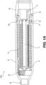
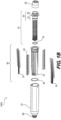
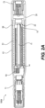
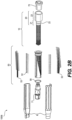
- FIGS. 1A-2B cut-away side views and exploded views of rotary devices in accordance with various embodiments are shown.
- FIGS. 1A and 1B show a cable-to-cable rotary device 100A
- FIGS. 2A and 2B show a connector-to-connector rotary device 100B.
- Rotary devices 100A and 100B share various features of rotary devices in accordance with embodiments of the present disclosure that are described in greater detail below.
- a rotary device includes a rotor assembly 10.
- Each rotor assembly 10 includes a rotor shaft 11.
- the shaft may be formed or machined from of any of a variety of suitable materials, including both conductive and non-conductive materials, for example, metals or metal alloys, ceramics, or plastics.
- a rotor shaft 11 may be cylindrical with a substantially smooth or uniform surface.
- the shaft may have features to facilitate operative connection of the shaft to other components of the rotor assembly or operative connection of the rotor assembly to the stator assembly.
- the rotor shaft may have one or more longitudinal grooves, splines, or keys that engage a corresponding pattern in the hub of a slip ring element or other component of the rotor assembly.
- a rotor shaft may have transverse holes or grooves suitable for use with various retention devices, such as lock rings, retaining rings, snap rings, circlips, retention pins, or the like, that may be used to retain rotor assembly components such as slip ring elements or bearings on the rotor shaft.
- a rotor shaft 11 may have grooves 12 located adjacent to the ends of the rotor shaft that are suitable for use with retaining rings 13 which may be used to attach or retain various other components of the rotor assembly, such as a bearing 14.
- one or both ends of a rotor shaft may be threaded or otherwise shaped or contoured to mechanically engage a complementary portion of a rotary device, such as by a threaded connection, press-fit, or other interference connection.
- Rotor shafts having any type of feature suitable for connecting or engaging any other type of rotor assembly component or rotary device component along its length or at an end are within the scope of the present disclosure.
- a rotor assembly 10 also includes a rotor assembly coupler 20 connected to an end of the rotor shaft 11.
- a rotor assembly coupler 20 may be substantially cylindrical in shape and define an inner cavity with a substantially open end oriented outward from the rotary device and a second end with an axial hub defining a smaller opening suitable for receiving an end of a rotor shaft 11.
- a rotor assembly coupler 20 may be connected to a rotor shaft 11 using any suitable means, including, for example, a threaded, press-fit, or other interference connection. As illustrated in the rotor assembly 10 shown in FIG.
- the rotor shaft 11 may be configured with a circumferential groove 12 adjacent an end of the shaft which is inserted into the axial hub of the rotor assembly coupler 20 and fit with a retaining ring 13 which serves to retain an end of the rotor shaft 11 in the rotor assembly coupler.
- a rotor assembly coupler 20 may also include a stator interface portion 21 with an outer surface configured to fit an interior portion of the stator 51.
- the stator interface portion 21 may further include an o-ring 22 or other gasket, packing, or seal to sealably engage the inner surface of a stator during rotation of the rotor assembly coupler 20 with respect to a stator 51.
- the stator interface portion 21 of a rotor assembly coupler 20 may serve as a bearing such as an integral plain bearing or friction bearing and provide a surface for rotational engagement of an interior portion of the stator.
- a rotor assembly coupler 20 or stator interface portion 21 may also include a separate bearing to facilitate rotational engagement of a rotor assembly with a stator of a rotary device.
- a rotor assembly coupler may include a bearing, bushing, or the like that mechanically engages a portion of a stator, such as by a press-fit, providing for both axial and radial retention of a rotor assembly within a stator of a rotary device as well as facilitating smooth rotational coupling of the components of a rotary device.
- a surface of rotor assembly coupler 20 oriented toward the interior of the rotary device is used to retain the slip ring elements 30 or other components of the rotor assembly on the rotor shaft 11.
- the surface of the rotor assembly coupler 20 oriented toward the interior of the rotary device may also include a feature or features that mechanically engage the adjacent slip ring elements or other rotor assembly components and prevents them from rotating about the rotor shaft 11 with respect to the rotor assembly coupler 20. This may include one or more surface projections or depressions configured to engage a complementary feature of the adjacent rotor assembly component.
- the stator interface portion 21 and an attachment portion 23 of the rotor assembly coupler 20 may be supported about an axial hub of the rotor assembly coupler by two or more support arms extending radially outwardly from the axial hub of the rotor assembly coupler. Spaces between the axial hub, the support arms, and the outer circumference of the rotor assembly coupler that align with corresponding spaces in insulator discs or other components of the rotor assembly may permit routing of rotor assembly leads 37 from the slip ring elements 30 to the interior of the rotor assembly coupler 20.
- the axial hub and support arms of a rotor assembly coupler may comprise the surface of the rotor assembly coupler oriented toward the interior of the rotary device or may be located near the interior end of the rotor assembly coupler.
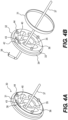
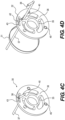
- the rotor assembly 10 includes a plurality of slip ring elements 30. As illustrated in FIGS. 3-4D , each slip ring element 30 comprises a slip ring 31 and an insulator disc 32.
- each slip ring 31 is a conductive, ring-shaped structure
- each insulator disc 32 is a substantially non-conductive, disc-shaped structure that provides support for a slip ring 31 with respect to the rotor shaft 11 and also provides for electrical isolation of adjacent slip rings 31 in the rotor assembly 10.
- each slip ring element of a rotary device may have substantially identical physical and electrical specifications.
- the modular nature of each slip ring element may facilitate assembly of rotary devices comprising a plurality of physically and electrically uniform slip ring elements, thereby providing for uniform and reliable mechanical and electrical performance of the rotary device.
- a slip ring element may be individually provided with a particular component (i.e., a slip ring or insulator disc) or specification to produce a desired electrical performance for a particular slip ring connection within a rotary device.
- a particular slip ring element may have a slip ring comprising a conductive material that differs from that of the slip rings of other slip ring elements of the device to provide for a particular electrical performance specification for the corresponding electrical connection.
- a particular slip ring element of a device may have a different physical specification such as an axial length of a slip ring portion, an insulator portion, or both, that spans multiple slide contact positions of a corresponding stator assembly.
- the modular nature of the slip ring elements and the rotary devices comprising the slip ring elements may variously provide for improved uniformity or improved capacity for customization of a rotary device.
- the slip rings 31 of slip ring elements 30 are made of a metal or metal alloy, for example, copper, beryllium-copper, brass, or the like.
- the slip rings 31 may be further treated, for example, by coating with a precious metal such as gold to enhance the conductivity and/or electrical performance of the electrical connection between the slip ring and the slide contact of the stator assembly.
- the slip rings 31 may be polished or otherwise provided with physical properties or specifications that may enhance the performance of a slip ring electrical connection, such as by providing for an enhanced signal to noise ratio.
- the slip rings may be manufactured, for example, by cutting rings of the desired width from metal tubing having the required material and dimensional specifications.
- slip rings may be comprised of conductive polymers.
- slip rings may be manufactured of any material that may be provided with a conductive surface, such as by thin film metal deposition using any of a variety of chemical or physical deposition techniques. Any manner of manufacturing a slip ring from any material or combination of materials to produce a slip ring suitable for conducting electrical signal between a slide contact and a conductor electrically connected to the slip ring is within the scope of the present disclosure.
- the insulator disc 32 of each slip ring element 30 is a generally disc-shaped structure that is substantially non-conductive.
- substantially non-conductive As used herein, the terms “substantially non-conductive,” “insulative,” “dielectric,” and variations thereof may be used interchangeably to describe a material or structure that generally does not conduct an electrical current.
- a substantially non-conductive structure may be constructed of material that is non-conductive, or may be constructed of a conductive material such as a metal that is rendered substantially non-conductive by treatment of the material or structure, for example, by coating a conductive structure with a non-conductive material.
- substantially non-conductive materials may include materials with high resistivity, such as glass, ceramics, polymers, plastics, composites, or the like.
- An insulator disc 32 comprises a slip ring portion 33 with a first outer circumference and a spacer portion 34 with a second outer circumference that is greater than the first outer circumference.
- the circumferential edge of the insulator disc 32 in such an embodiment has a "stepped" appearance from a profile perspective (i.e., a two-level outer circumference profile) due to the different diameters of slip ring portion 33 and spacer portion 34 of the insulator disc.
- the insulator disc 32 may be substantially cylindrical in shape (i.e., generally having the shape of a right cylinder), for example, having a slip ring portion side (i.e., front face) and a spacer portion side (i.e., rear face) of the insulator disc that are both generally flat, with the exception of certain features that are described in greater detail herein.
- the insulator discs may have shapes or profiles that depart from a generally cylindrical shape and may have, for example, a domed, conical, or irregular shape, while still having a substantially circular cross section coaxial to the rotor shaft 11 and a two-level outer circumference including a slip ring portion 33 and a spacer portion 34, as described above. Any of a variety of insulator disc shapes or profiles is possible and included within the scope of the present disclosure.
- FIGS. 4A-4F various views of a slip ring element 30 are shown, illustrating an insulator disc 32 having with three radial arms 36 extending from the hub 35 to the slip ring portion 33 and spacer portion 34. Spaces 40 between the hub 35, the radial arms 36, and the slip ring portion/spacer portion 33/34 permit rotor assembly leads 37 to be run from each slip ring 31 to the rotor assembly coupler 20, thereby facilitating electrical connection of each slip ring with the rotor assembly end of a rotary device.
- An opening at the axis of the hub 35 of each insulator disc 32 is configured to receive the rotor shaft 11.
- An insulator disc 32 may further include various features that facilitate termination of a rotor assembly lead 37 and electrical connection of the rotor assembly lead to the slip ring 31 of each slip ring element 30.
- an insulator disc 32 may include a channel 41 in the spacer portion-side surface (i.e., the rear face) of the insulator disc extending from a space 40 to a terminal penetration 42 through the spacer portion 34.
- a channel 41 may be of a suitable width, depth, and configuration to receive an insulated portion of a rotor assembly lead 37 and to mechanically retain the rotor assembly lead 37, such as by a press-fit interface (i.e., an interference fit or friction fit).
- a terminal penetration 42 through the spacer portion 34 is configured to permit an uninsulated terminal 38 of a rotor assembly lead 37 to pass through the spacer portion 34 of an insulator disc 32 and contact a slip ring 31.
- the terminal 38 of the rotor assembly lead 37 is located between the first outer circumference of the slip ring portion 33 of the insulator disc 32 and the inner surface of the slip ring 31.
- An insulator disc may further include an arcuate deflection channel 43 located radially inward relative to the first outer circumference of the slip ring portion 33 and the terminal penetration 42.
- a deflection channel 43 permits the portion of the insulator disc located between the first outer circumference and the deflection channel 43 to elastically or resiliently flex or deflect to accommodate a terminal 38 of a rotor assembly lead 37 beneath a slip ring 31 while exerting sufficient constant pressure on the terminal 38 to maintain the terminal in fixed, electrical contact with the slip ring 31.
- the terminal 38 of a rotor assembly lead 37 is electrically connected to the slip ring 31 by a press-fit of the slip ring over the first outer circumference of the insulator disc, with the terminal 38 mechanically fixed between the slip ring and the insulator disc by compression of the terminal between the slip ring 31 and the first outer circumference of the insulator disc 32.
- the first outer circumference of an insulator disc may further include a depressed region to accommodate a terminal 38 of a rotor assembly lead 37 beneath a slip ring 31.
- an insulator disc may include an axial groove of suitable dimensions for receiving a terminal and maintaining it in electrical contact with a slip ring, rather than a deflection channel or a depressed region.
- an insulator disc may include channels, grooves, or penetrations that permit routing of the terminal of a rotor assembly lead transverse to the axis of the rotor assembly (i.e., parallel to or concentric with the circumference of the slip ring).
- any configuration of an insulator disc that permits routing and securing of a portion of a rotor assembly lead and/or terminal with respect to the insulator disc and slip ring and that places the terminal in electrical contact with the slip ring is within the scope of the present disclosure.
- Insulator discs may also include structures or features that permit an insulator disc to operatively engage an adjacent surface.
- an insulator disc may have projections 44 extending from a face of the insulator disc such as the front face of an insulator disc 32.
- the projections 44 may be configured to engage an adjacent component of the rotor assembly by fitting within corresponding recesses 45 in the adjacent component, such as the rear face of another insulator disc 32 or a surface of the rotor assembly coupler.
- the projections 44 and corresponding recesses may interface by a press-fit or a snap-fit connection.
- Projections 44 and corresponding recesses in an adjacent component may be configured such that an insulator disc 32 is torsionally fixed with respect to the adjacent component. In this manner, a plurality of slip ring elements may be assembled to form a substantially torsionally fixed rotor assembly.
- insulator discs may be formed or manufactured with a unitary construction.
- insulator discs may be molded from a non-conductive thermoplastic resin.
- each insulator disc may be comprised of multiple, separate components that are joined to form an insulator disc.
- each insulator disc may be comprised of a slip ring portion that is separate from the spacer portion.
- separate components of an insulator disc may be permanently joined, or may be modularly assembled using features such as the projections and recesses described above.
- each hub 35 has a circular opening at its axis, and the rotor shaft 11 has a circular cross section.
- the opening at the axis of each hub 35 may be sized such that the opening is complementary to the diameter of rotor shaft 11 and the insulator discs slide on freely (i.e., a loose or light interference fit).
- the opening may be undersized with respect to the diameter of rotor shaft 11, such that the insulator discs 32 are press-fit onto the rotor shaft 11 to provide an interference fit with a suitable strength of fit to provide resistance to axial and torsional movement of the insulator disc relative to the rotor shaft following installation of the insulator disc on the rotor shaft.
- the hub of an insulator disc and the rotor shaft may have other cross sectional profiles, such as parallel keyed configurations or the like, that provide a hub joint with resistance to torsional movement of an insulator disc about the rotor shaft while still permitting modular assembly of slip ring elements on the rotor shaft.
- the axial lengths of the slip ring elements or portions thereof in a rotor assembly may vary.
- the rotary devices 100A and 100B illustrated in FIGS. 1A-2B each comprise 34 uniform slip ring connections.
- a rotary device including various components of the illustrated devices, such as a stator 51, a rotor shaft 11 and rotor assembly coupler 20, and housing components may be configured to have a variety of numbers and configurations of electrical connections by varying the configuration of the slip ring elements and the slide contacts.
- insulator discs with varying axial lengths (i.e., thicknesses) of the spacer portion 34 may be used to provide the necessary electrical resistance between adjacent slip rings 31.
- Varying axial lengths of a spacer portion 34 of a slip ring element 30 may be produced by using multi-component insulator discs having multiple, separate spacer portions, or by using insulator discs having a unitary construction and a range of available sizes with respect to the axial length of the spacer portion 34.
- insulator discs with varying axial lengths of the slip ring portion 33 may be used in a rotor assembly.
- an insulator disc with an extended slip ring portion 33 may be provided to accommodate longer slip rings 31 that could be used to make electrical contact with more than one slide contact to accommodate greater electrical current through the slip ring.
- Varying axial lengths of a slip ring portion 33 of a slip ring element 30 may be produced in a manner similar to that described above with respect to the spacer portion.
- an elongated slip ring portion of a slip ring element may comprise three separate slip ring portion components, each separately sliding on to rotor shaft 11 and each receiving a rotor assembly lead 37, with an elongated slip ring fitting over the three slip ring portion components and rotor assembly leads and making contact with as many as three rotor assembly lead terminals 38 in this example.
- a rotor assembly of the present disclosure may be modularly or scalably configured, and a rotary device having a variety of electrical connection configurations may be achieved using various combinations of components that can be modularly assembled.
- a rotary device in accordance with various embodiments of the present disclosure and as illustrated in FIGS. 1A-2B includes a stator assembly 50.
- the stator assembly 50 comprises a stator 51, a plurality of slide contacts 52, and a plurality of stator assembly leads 53.
- the stator 51 is cylindrically shaped and defines a cavity configured to receive a rotor assembly 10.
- stator 51 of a stator assembly 50 is substantially non-conductive.
- a stator 51 may be formed or machined from of any of a variety of suitable materials, including both conductive and non-conductive materials, for example, metals or metal alloys, ceramics, or plastics.
- a stator 51 constructed from a conductive material may be rendered substantially non-conductive by coating or otherwise treating it with a non-conductive material.
- a stator 51 may have various features to facilitate operative connection of the rotor shaft 11.
- the cavity of a stator 51 may include a bearing configured to receive an end of a rotor shaft 11 and provide for rotation of the rotor assembly 10 within the stator 51.
- the interior surface of the cavity of the stator 51 may also have dimensions or features that permit operational engagement of rotor assembly 10.
- the cavity of stator 51 may be configured to receive a bearing or bearings located at one or both ends of the rotor assembly 10, such as by a press-fit connection, thereby providing for axial and radial retention of the rotor assembly 10, with the bearing or bearings providing for rotation of the rotor assembly within the stator.
- the interior surface of the cavity of a stator may be configured to engage one or more o-rings or other gaskets, seals, or packings such that the interior of the rotary device is protected from external fluids or contaminants throughout dynamic interaction (i.e., rotation) of the rotor assembly with respect to the stator.
- the interior surface of the cavity of a stator may be configured o-rings or other seals. Any of a variety of configurations of a stator and a rotor assembly that facilitate retention and rotation of the rotor assembly 10 within the stator 51, along with sealing of the slip ring connections within the rotary device and protection of the slip ring connections from environmental conditions external to the rotary device, are within the scope of the present disclosure.
- a stator 51 also includes features for electrically connecting components of the stator assembly 50 to the slip rings 31 of each slip ring element in the rotor assembly.
- a stator 51 may include slide contact penetrations 54 for insertion of each slide contact 52.
- a stator 51 also includes grooves or channels 55 along the exterior surface of the stator for routing of the stator assembly leads 53 from the end of the stator to each slide contact 52 and for mechanically and electrically connecting a stator lead terminal 56 of each stator assembly lead 53 to each slide contact 52.
- portions of the exterior surface of a stator 51 may be configured with a relieved region or a decreased diameter to accommodate parallel routing of a plurality of stator assembly leads 53 within a stator housing 61.
- the channels 55 in a stator 51 are oriented along circumferential arcs of the outer surface of the stator and provide for retention of the stator assembly leads 53 and alignment of the stator lead terminals 56 with the slide contacts 52 and with the slip rings 31 of the rotor assembly 10.
- the lengths of the channels 55 are progressively longer from the stator end of the stator 51 to the rotor end by a distance approximately equal to the distance between every other slip ring of the rotor assembly.
- Such a configuration permits orderly parallel routing of stator assembly leads that terminate at a row of slide contacts running parallel to the axis of the rotary device.
- the stator assemblies 50 illustrated in FIGS. 1B and 2B each include two rows of slide contacts oriented substantially perpendicularly to the axis of the rotary device and on opposite sides of stator 51, with the slide contacts 52 in each row aligning with every other slip ring 31 in the rotor assembly 10.
- This arrangement of the slide contacts 52 with respect to the slip ring elements of a rotor assembly in accordance with various embodiments is illustrated in greater detail in FIGS. 5-6D .
- FIG. 5 shows a perspective view of a rotor assembly in accordance with various embodiments and the relative positions of slide contacts 52 arranged in two rows on opposite sides of the rotor assembly with the stator removed for purposes of illustration.
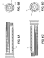
- FIGS. 6A-6D illustrate a partially assembled rotary device in accordance with various embodiments showing two rows of slide contacts 52 on opposite sides of the stator, with the top view ( FIG. 6A ) showing slide contacts aligned with odd-numbered slip ring element positions and the bottom view ( FIG. 6C ) showing slide contacts aligned with even-numbered slip ring element positions of the rotary device.
- FIGS. 6B and 6D illustrate representative cross-section views of a rotary device at an odd-numbered slip ring element position and an even-numbered slip ring element position, respectively, to show the relative position and orientation of a slide contact 52 and a slip ring 31.
- Such an even radial and axial distribution of slide contacts within a rotary device may provide for a symmetrical or balanced distribution of frictional and/or pressure forces between the stator assembly and the rotor assembly.
- stators having any number of rows of slide contacts distributed symmetrically or asymmetrically about the circumference of the stator and having slide contacts aligned with slip rings in any possible sequence are within the scope of the present disclosure.
- stators having slide contacts arranged in other patterns, such as spirals or other non-linear patterns are also within the scope of the present disclosure.
- each stator assembly lead 53 adjacent to the stator lead terminal 56 of the lead and fitting in channel 55 may be mechanically fixed in the channel 55 using an interference fit such as a series of alternating projections 57 in the side wall of each channel.
- the stator lead terminal 56 of each stator assembly lead 53 may be likewise mechanically secured by and electrically connected to a slide contact 52 by insertion of the slide contact into a slide contact penetration 54 in the wall of the stator 51.
- a fixed end of each slide contact is press-fit into a slide contact penetration 54 and retained in position by an interference fit.
- each slide contact 52 retains the stator lead terminal 56 between a bend or curve of the fixed end of the slide contact and a portion of the exterior surface of the stator.
- each stator lead terminal 56 may further be press-fit into a channel approximating the size of the terminal.
- each slide contact 52 extends into the cavity of stator 51 and makes contact with a slip ring 31, as shown in FIG. 7 .
- the slide contacts 52 may be biased to maintain mechanical contact and an electrical connection with the slip rings 31 by the orientation of the slide contact penetrations 54 and/or the configuration of the slide contacts 52.
- the slide contacts 52 may be configured so that they are resiliently biased toward the slip rings 31 after installation in the stator 51.
- the slide contacts are constructed of a conductive material and may be formed, for example, of a wire bent or formed to a suitable configuration or by cutting, stamping, or etching from a sheet of material.
- the free end of The ostantially straight, contacting a slip ring tangentially as illustrated in FIG. 7 , or the free end of each slide contact may have an arc or bend that corresponds to a portion of the circumference of a slip ring and increases the contact area between the slip ring and the slide contact.
- a rotary device includes a housing configured to cover or encase the device.
- a housing may be configured to protect the rotary device and the electrical connections therein from the external environment.
- a housing is generally non-conductive, and may be constructed of a material that is substantially non-conductive or may be constructed of a conductive material that is treated to render the housing substantially non-conductive.
- a housing comprises of one or more components, such as a stator housing 61 and a rotor assembly coupler overmold 62.
- a portion of a rotary device or rotary device component may comprise a portion of the external surface of the finished device without being further covered by or encased in a housing component such as a rotor assembly coupler overmold.
- a stator housing 61 may be constructed as a unitary piece, as illustrated in FIGS. 1A and 1B , and configured to receive a stator assembly 50 and to retain the stator assembly by a threaded connection, press-fit, snap-fit, or other interference fitting of the stator housing over the stator assembly.
- a stator housing 61 may comprise multiple pieces that are fit together over a stator assembly 50 and joined by any of a variety of suitable means, such as by a snap-fit, adhesive connection, welded connection, or the like.
- the stator 51 and/or stator housing 61 may further include one or more o-rings 58 or other gaskets, seals, or packings to provide a seal between the stator assembly and the stator housing at one or both ends of the stator and to prevent external fluids or other contaminants from contacting the stator assembly.
- a stator housing 61 may also provide for further retention of the slide contacts 52 in the slide contact penetrations 54 of the stator and help to maintain mechanical and electrical contact of the fixed end of the slide contacts with the stator lead terminals 56.
- rotor assembly coupler 20 of rotor assembly 10 may be encased by a rotor assembly coupler overmold 62.
- a rotor assembly coupler overmold 62 may be configured and attached to the rotor assembly coupler 20 or to the attachment portion 23 of a rotor assembly coupler in a manner similar to that described above for a stator housing 61.
- a stator housing 61 may be configured for attachment to a sheath, housing, or other external protective covering of a multi-conductor electrical cable.
- a stator housing 61 may terminate in a male press-fit cable sheath connection 63 resembling a hose barb fitting over which a cable sheath (not shown) may be fit to provide a sealed connection between the rotary device 100A and an electrical cable to a remote device.
- the rotor assembly coupler overmold 62, rotor assembly coupler 20, or attachment portion 23 of a rotor assembly coupler may be similarly configured to accept an electrical cable sheath (not shown).
- rotor assembly coupler 20 is configured to receive a cable within the cavity of the rotor assembly coupler.
- wire leads from the rotary device extend outward from the device to remote devices, connectors, or other components.
- rotor assembly wire leads 37 may extend outwardly from the rotor end of the cable-to-cable rotary device 100A through an attached cable sheath (not shown) to a first remote electronic device.
- stator assembly leads 53 may extend outwardly from the stator assembly end of the rotary device 100A through an attached cable sheath (not shown) to a second remote electronic device.
- rotary device 100A can permit a first remote electronic device and a second remote electronic device to be rotated freely with respect to one another without twisting or binding of the of the connecting cable while maintaining a continuous electrical connection across multiple electrical channels.
- a rotary device may include connectors (i.e., male plug connectors, female socket or receptacle connectors, or any type of device for providing an interface between electrical circuits using a mechanical assembly) at one or both ends of the rotary device for making electrical connections between the rotary device and remote electrical devices.
- a connector-to-connector rotary device 100B may comprise a male plug connector 71 on the stator end of the rotary device and a female connector 72 on the rotor end of the rotary device.
- the connectors may be configured to support multiple discrete electrical channels that may be electrically connected to the rotor assembly leads (not shown) for a connector at the rotor end or to the stator assembly leads 53 at the stator end.
- connectors may be selected or configured to provide for resistance to entry of fluid or other external contaminants and be suitable for use, for example, intraluminally or intravascularly.
- a first remote electronic device may be connected to the male plug connector 71 of rotary device 100B, and a second remote electronic device may be connected to the female connector 72 using corresponding mateable connectors. In this manner, rotary device 100B can permit a first remote electronic device and a second remote electronic device to be rotated freely with respect to one another without twisting or binding of the of the connecting cable while maintaining a continuous electrical connection across multiple channels.
- any type of connector that permits parallel conduction of separate electrical channels through the connector such as a multi-pin connector, may be used.
- a wide variety of connectors are known to persons of ordinary skill in the art, including such connectors as are described and illustrated in U.S. Patent numbers 7,326,091 , 7,661,995 , 7,938,670 , D596,127 , D615,932 , and D616,825 .
- FIGS. 1B and 2B having a male plug connector at one end and a female connector at the other end of the rotary device is for purposes of illustration only.
- any type of connector or combination of connectors may be used at the ends of a rotary device without limitation to any particular combination of connector gender or type.
- a rotary device may have a connector at one end and a cable connection at the other end.
- Rotary devices having any of the range of possible permutations of the various end configurations described above are within the scope of the present disclosure.
- either the rotor assembly leads 37, or the stator assembly leads 53, or both may terminate at and electrically connect to the connectors at the respective ends of the device in any suitable manner.
- the connectors may be connected to the rotor assembly coupler 20 or the end of the stator 51 opposite the rotor assembly coupler 20 using any suitable means, for example, a press-fit, threaded fit, bayonet connector, or any other interference, welded, brazed, or adhesive fit.
- the interface between the stator 51 or rotor assembly coupler 20 and a connector may be configured such that mechanical attachment of the connector simultaneously provides for electrical connection of the stator assembly leads 53 or the rotor assembly leads 37 to the attached connector.
- electrical connection of the leads to a connector may be made separately from attachment of the connector to the stator assembly end or rotor assembly coupler using any suitable means, either before or after attachment of the connector to the stator assembly end or the rotor assembly coupler.
- the rotary device is suitable for use in a medical device.
- a rotary device as disclosed herein may be used to electrically connect a first remote electronic device that may deployed in the body of a human patient to a second remote electronic device that may remain outside of the body of the human patient.
- Various medical devices such as an electronic instrument, apparatus, or implant deployed within a body lumen or cavity may require rotation during insertion or operation while attached to an external electronic device such as a power source, monitor, data recorder, or computer by an electrical cable.
- an external electronic device such as a power source, monitor, data recorder, or computer by an electrical cable.
- the ability to freely rotate the first remote electronic device while continuously maintaining an electrical connection with the external electronic device and without twisting, kinking, binding or jamming of the connecting electrical cable due to rotation of the first electronic device during a medical procedure is desirable.
- Rotary devices disclosed herein are suitable for use in medical facility such as a hospital or operating room or other patient care or diagnostic facility.
- a rotary device may be compatible with the electronic performance requirements of any type of electronic device, including any type of medical electronic device, with respect to specifications such as current, voltage, impedance, and signal to noise ratio.
- a rotary device in accordance with various embodiments may be configured with components having specifications suitable for low voltage/low amperage current and signal transmission with low noise and high signal quality.
- a rotary device may provide the physical performance specifications required in various medical settings, including, for example, resistance to entry of water or other fluids and the ability to meet regulatory requirements for single use and/or reusable devices with regard to cleanliness or sterilization.
- the rotary devices disclosed herein may also provide an ability to meet other physical requirements associated with medical device applications such small size and biocompatibility.
- a method of assembling a customized rotary device may comprise steps of determining the number of electrical channels required by the components to be connected, as well as determining the electrical specification requirements for each channel.
- a method may further include selecting a rotor and stator assembly of the appropriate size, including the appropriate length and diameter.
- the method may comprise selecting a rotor and stator assembly having the desired ends, such as cable ends or connector ends, based on the manner in which the rotary device will be attached to the remote components of the system.
- the connector ends or cables may be attached to the rotor and stator as described above.
- a method may further comprise attaching connectors to the electrical cables of the components to be connected, wherein the connectors correspond to or are compatible with connectors of the rotary device or connectors that may be located at the remote ends of cables extending from the rotary device.
- FIG. 9 presents a flowchart 900 of a method of assembling a rotary device, such as the rotary devices 100A and 100B.
- slip ring elements are assembled, such as the slip ring 31.
- slip ring elements are placed onto a rotor shaft, such as the rotor shaft 11. Slip ring elements may be added to the rotor shaft and connected to a rotor assembly lead as disclosed herein.
- the number and configuration of the slip ring elements including the axial length (i.e., thickness) of the spacer portion and/or the axial length of the slip ring may be varied or selected based on the electrical performance requirements of the system connected by the rotary device. For example, an insulator disc with an increased axial length of the spacer portion may be selected to provide greater isolation of adjacent slip rings that may carry greater current or power. Similarly, longer slip rings may be selected and installed in connection to multiple rotor assembly leads and making contact with multiple slide contact such that the same electrical signal is carried by multiple parallel leads in the connected system.
- slip ring elements are secured to form a rotor assembly, such as the rotor assembly 10.
- rotor assembly leads are routed through the spaces in the insulator discs and the terminals are connected to the insulator disc and the slip rings as described above. Portions of the length of the rotor assembly that are not required for making an electrical connection may be occupied by installing a spacer element of the appropriate length on the rotor assembly.
- stator such as the stator 51
- stator is assembled onto the rotor assembly.
- slide contacts such as the slide contacts 52
- stator assembly leads are connected to the slide contacts to form the stator assembly, such as the stator assembly 50.
- Stator assembly leads are routed along the outer portion of the stator and fixed in channels, and slide contacts are inserted into slide contact penetrations to mechanically secure and electrically connect the stator assembly lead terminals to the slide contacts.
- Slide contacts are inserted in positions in the stator corresponding to the appropriate slip rings of the rotor assembly and in the desired row, for example, to maintain a symmetrically balanced distribution of slide contacts about the rotor assembly.
- the stator assembly is covered with a housing or overmold, such as the overmold 62.
- a housing or overmold such as the overmold 62.
- the stator housing and the rotor assembly coupler overmold may be attached to the rotary device.
- the assembled rotary device may be packaged and sold in various configurations of cable-to-cable rotary devices, connector-to-connector rotary devices, or connector-to-cable rotary devices for installation in an electronic system by an end user or third party.
- a rotary device may be connected to or installed in an electronic system, for example, by the rotary device manufacturer or assembler.
- Rotary devices in accordance with various embodiments as described herein and methods of assembling the same may provide various benefits such as modularity and scalability that facilitate their application or use in a variety of systems and environments, as well as providing further benefits such as improved simplicity, reliability, and ease of manufacturing and assembly with respect to prior art devices and methods.
- stator and stator are applied for the sake of clarity and convenience with respect to components of the rotary devices described herein that are coupled in a rotationally operative manner.
- stator as used in the present disclosure is not limited to a fixed or non-moving portion of a rotary device. Rather, both the stator assembly and the rotor assembly of a rotary device as disclosed herein may rotate with respect to an external point of reference as well as with respect to each other.
- remote is used to refer to a device or connection that is located external to a rotary device at any distance from a rotary device.
Landscapes
- Engineering & Computer Science (AREA)
- Health & Medical Sciences (AREA)
- Manufacturing & Machinery (AREA)
- Biomedical Technology (AREA)
- Nuclear Medicine, Radiotherapy & Molecular Imaging (AREA)
- Radiology & Medical Imaging (AREA)
- Life Sciences & Earth Sciences (AREA)
- Animal Behavior & Ethology (AREA)
- General Health & Medical Sciences (AREA)
- Public Health (AREA)
- Veterinary Medicine (AREA)
- Motor Or Generator Current Collectors (AREA)
Claims (3)
- Dispositif rotatif (100A) approprié pour être utilisé dans un cathéter ou dans un dispositif médical insérable dans le corps d'un patient, comprenant :
un ensemble rotor (10) comprenant :un arbre de rotor (11) conçu pour tourner autour d'un axe longitudinal ;un coupleur d'ensemble rotor (20) ;une pluralité de fils d'ensemble rotor (37) ;une pluralité d'éléments de bague collectrice (30), chaque élément de bague collectrice (30) comprenant :une bague collectrice (31), etun disque isolant (32) configuré pour fournir un support à la bague collectrice (31) par rapport à l'arbre de rotor (11),chaque disque isolant (32) comportant :une partie bague collectrice (33) avec une première circonférence externe,une partie entretoise (34) ayant une seconde circonférence externe supérieure à la première circonférence externe, etun moyeu (35) conçu pour recevoir l'arbre de rotor (11) et relié à la partie bague collectrice et à la partie entretoise par au moins deux bras de support (36),la pluralité d'éléments de bague collectrice (30) étant positionnés sur l'arbre de rotor (11), positionnés axialement adjacents les uns aux autres,chacune de la pluralité de bagues collectrices (31) étant reliée électriquement à au moins l'un de la pluralité de fils d'ensemble rotor (37), chaque disque isolant (32) étant en outre conçu pour assurer l'isolation électrique des bagues collectrices adjacentes (31) dans l'ensemble rotor (10) ;un ensemble stator (50) conçu pour engager en rotation le coupleur d'ensemble rotor et comprenant :un stator (51) incluant une ou plusieurs rainures ou canaux (55) orienté(e)s le long d'un arc circonférentiel d'une surface externe du stator (51), et ledit stator (51) ayant une cavité qui est conçue pour recevoir l'ensemble rotor ;une pluralité de fils d'ensemble stator (53) ;une pluralité de contacts glissants (52), chaque contact glissant étant relié mécaniquement au stator (51), la pluralité de contacts glissants (52) étant reliés électriquement à au moins l'un de la pluralité de fils d'ensemble stator (53) et à au moins l'une de la pluralité de bagues collectrices (31),la pluralité de fils d'ensemble stator (53) étant acheminés depuis une extrémité du stator (51) vers des contacts glissants respectifs (52) dans la ou les rainures ou canaux (55) et étant conçus pour se connecter électriquement à un contact glissant respectif (52) de la pluralité de contacts glissants (52) ; etun boîtier comportant un boîtier de stator (61) et un surmoulage de coupleur d'ensemble rotor (62), dans lequel le boîtier est conçu pour recouvrir le dispositif rotatif. - Dispositif rotatif (100A) selon la revendication 1, dans lequel un espace (40) est défini par chacun de la pluralité de disques isolants (32) entre le moyeu (35), les au moins deux bras de support (36), et la partie entretoise (34) ou la partie bague collectrice (33).
- Dispositif rotatif (100A) selon la revendication 1, dans lequel le stator (51) définit des pénétrations de contact glissant (54),
dans lequel un contact glissant de la pluralité de contacts glissants (52) est inséré dans la pénétration de contact glissant (54) et maintenu en place par un ajustement serré avec la pénétration de contact glissant (54).
Applications Claiming Priority (2)
| Application Number | Priority Date | Filing Date | Title |
|---|---|---|---|
| US201261721433P | 2012-11-01 | 2012-11-01 | |
| PCT/US2013/067994 WO2014071147A1 (fr) | 2012-11-01 | 2013-11-01 | Dispositif rotatif d'interconnexion électrique |
Publications (3)
| Publication Number | Publication Date |
|---|---|
| EP2915224A1 EP2915224A1 (fr) | 2015-09-09 |
| EP2915224A4 EP2915224A4 (fr) | 2016-06-08 |
| EP2915224B1 true EP2915224B1 (fr) | 2024-03-13 |
Family
ID=50547648
Family Applications (1)
| Application Number | Title | Priority Date | Filing Date |
|---|---|---|---|
| EP13850584.7A Active EP2915224B1 (fr) | 2012-11-01 | 2013-11-01 | Dispositif rotatif d'interconnexion électrique |
Country Status (4)
| Country | Link |
|---|---|
| US (2) | US9039423B2 (fr) |
| EP (1) | EP2915224B1 (fr) |
| IL (1) | IL238472B (fr) |
| WO (1) | WO2014071147A1 (fr) |
Families Citing this family (15)
| Publication number | Priority date | Publication date | Assignee | Title |
|---|---|---|---|---|
| DE102012220293A1 (de) * | 2012-11-07 | 2014-05-08 | Wobben Properties Gmbh | Schleifringübertrager |
| EP2765660A1 (fr) * | 2013-02-07 | 2014-08-13 | ABB Technology AG | Ensemble de bagues collectrices |
| GB2532802B (en) * | 2014-11-29 | 2017-03-29 | Orange Music Electronic Company Ltd | Rotatable Coupling for Audio Cables |
| CN105375217B (zh) * | 2015-11-27 | 2017-09-22 | 中航光电科技股份有限公司 | 一种复合汇流环 |
| DE102016203762A1 (de) * | 2016-03-08 | 2017-09-14 | Krones Ag | Schleifringübertrager für Rundläufermaschinen |
| JP6792445B2 (ja) * | 2016-12-27 | 2020-11-25 | ジェコー株式会社 | スリップリング、該スリップリングを備える回転センサ装置、及びスリップリングの製造方法 |
| DE102017007857A1 (de) * | 2017-08-23 | 2019-02-28 | Deckel Maho Pfronten Gmbh | Spindelvorrichtung zum Einsatz an einer numerisch gesteuerten Werkzeugmaschine |
| CN108123347A (zh) * | 2017-11-17 | 2018-06-05 | 深圳市科比特航空科技有限公司 | 连接器及无人机 |
| CN111009793B (zh) * | 2019-12-10 | 2023-01-13 | 中船航海科技有限责任公司 | 一种微型导电环组件及其制备方法 |
| CN112290336B (zh) * | 2020-08-19 | 2022-04-08 | 扬州船用电子仪器研究所(中国船舶重工集团公司第七二三研究所) | 一种多功能一体化综合汇流环结构 |
| CN113783058B (zh) * | 2021-10-29 | 2025-02-07 | 九江精密测试技术研究所 | 一种免拆装的自清洁滑环 |
| CN115089871B (zh) * | 2022-07-19 | 2025-03-18 | 景昱医疗科技(苏州)股份有限公司 | 刺激施加系统及其转接装置 |
| EP4485714A1 (fr) | 2023-06-27 | 2025-01-01 | Schleifring GmbH | Bloc de support pour former un module de bague collectrice modulaire autoportant |
| CN119355882B (zh) * | 2024-09-06 | 2025-11-25 | 中船九江精达科技股份有限公司 | 一种光电滑环堆栈装置的安装与调试方法 |
| CN119542861B (zh) * | 2024-11-30 | 2026-03-24 | 中航光电科技股份有限公司 | 一种模块化电旋连接器 |
Citations (1)
| Publication number | Priority date | Publication date | Assignee | Title |
|---|---|---|---|---|
| WO2011063444A1 (fr) * | 2009-11-30 | 2011-06-03 | Cathrx Ltd | Manche de cathéter |
Family Cites Families (22)
| Publication number | Priority date | Publication date | Assignee | Title |
|---|---|---|---|---|
| US3297973A (en) * | 1963-08-30 | 1967-01-10 | Poly Scient Corp | Floating-brush contact assembly |
| US4080540A (en) * | 1973-10-08 | 1978-03-21 | Canon Kabushiki Kaisha | Low-powdered stepping motor |
| US4329606A (en) * | 1979-12-10 | 1982-05-11 | General Scanning, Inc. | Electric motor construction |
| JP3446313B2 (ja) * | 1993-08-30 | 2003-09-16 | 株式会社デンソー | 回転電機の回転子 |
| AU3737997A (en) * | 1996-07-30 | 1998-02-20 | Fifth Dimension, Inc. | Brushless slip ring using rolling elements as electrical conductors |
| JP3607928B2 (ja) * | 2001-01-31 | 2005-01-05 | ビー・エル・オートテック株式会社 | ロータリジョイント |
| GB0130602D0 (en) * | 2001-12-21 | 2002-02-06 | Johnson Electric Sa | Brushless D.C. motor |
| US7001184B2 (en) * | 2002-12-20 | 2006-02-21 | Unit Industries | Slip ring with connector pins |
| DE10324708A1 (de) * | 2003-05-30 | 2004-12-16 | Ltn Servotechnik Gmbh | Schleifringelement und Verfahren zu dessen Herstellung |
| US7119471B2 (en) * | 2003-07-16 | 2006-10-10 | Motor Kinetics, Inc. | Direct drive high torque compact synchronous motor |
| DE10361859A1 (de) * | 2003-12-30 | 2005-08-11 | Robert Bosch Gmbh | Elektrische Maschine und dazu vorgesehener Ständer |
| ITMI20071486A1 (it) | 2007-07-24 | 2009-01-25 | Ravioli S P A | Collettore elettrico rotante |
| TWM331247U (en) * | 2007-10-05 | 2008-04-21 | Taiwan Long Hawn Entpr Co | Assembly slip ring |
| JP2009118615A (ja) * | 2007-11-05 | 2009-05-28 | Mitsuba Corp | ブラシレスモータ |
| DK200801474A (en) * | 2008-10-27 | 2009-11-19 | Vestas Wind Sys As | Slip ring assembly with shaft holder |
| EP2309608B1 (fr) * | 2009-10-09 | 2014-03-19 | Ondal Medical Systems GmbH | Couplage électrique rotatif et connecteur associé |
| JP5014445B2 (ja) * | 2010-02-10 | 2012-08-29 | 三菱電機株式会社 | 電力供給ユニット一体型回転電機 |
| JP5729091B2 (ja) * | 2010-10-29 | 2015-06-03 | 日本電産株式会社 | バスバー、モータ及びこれらの製造方法 |
| JP2012099376A (ja) * | 2010-11-04 | 2012-05-24 | Nidec Servo Corp | スリップリング装置 |
| JP2012110188A (ja) * | 2010-11-19 | 2012-06-07 | Nippon Densan Corp | 中間接続部材、ステータ及びモータ |
| US8499438B2 (en) * | 2011-02-28 | 2013-08-06 | GM Global Technology Operations LLC | Systems and methods for joining wires of a motor stator |
| US9021684B2 (en) * | 2011-04-19 | 2015-05-05 | Tyco Electronics Corporation | Method of fabricating a slip ring component |
-
2013
- 2013-11-01 EP EP13850584.7A patent/EP2915224B1/fr active Active
- 2013-11-01 US US14/069,752 patent/US9039423B2/en active Active
- 2013-11-01 WO PCT/US2013/067994 patent/WO2014071147A1/fr not_active Ceased
-
2015
- 2015-04-21 US US14/692,653 patent/US9437996B2/en active Active
- 2015-04-26 IL IL238472A patent/IL238472B/en active IP Right Grant
Patent Citations (1)
| Publication number | Priority date | Publication date | Assignee | Title |
|---|---|---|---|---|
| WO2011063444A1 (fr) * | 2009-11-30 | 2011-06-03 | Cathrx Ltd | Manche de cathéter |
Also Published As
| Publication number | Publication date |
|---|---|
| US20150229086A1 (en) | 2015-08-13 |
| EP2915224A1 (fr) | 2015-09-09 |
| US9039423B2 (en) | 2015-05-26 |
| IL238472B (en) | 2020-04-30 |
| WO2014071147A1 (fr) | 2014-05-08 |
| EP2915224A4 (fr) | 2016-06-08 |
| US20140120742A1 (en) | 2014-05-01 |
| US9437996B2 (en) | 2016-09-06 |
| IL238472A0 (en) | 2015-06-30 |
Similar Documents
| Publication | Publication Date | Title |
|---|---|---|
| US9039423B2 (en) | Rotary electrical interconnect device | |
| EP2134406B1 (fr) | Ensemble connecteur enfichable en ligne pour utilisation avec des dispositifs médicaux | |
| US7822477B2 (en) | Connector assembly for use with medical devices | |
| US8668526B2 (en) | Bi-ventricular percutaneous cable | |
| US8708735B2 (en) | Splitter connector unit for electrical installations | |
| US20110098601A1 (en) | Medical device assembly having freedom of rotation | |
| JP2015527279A (ja) | 電気的フィードスルースペーサおよび接続性 | |
| EP1726066A2 (fr) | Ensemble empilable pour connexion directe entre un generateur d'impulsions et un corps humain | |
| CN102714384A (zh) | 可旋转电联接器和所述可旋转电联接器的连接器 | |
| CA2736204C (fr) | Ensemble connecteur electrique hyperboloide | |
| WO2011056520A2 (fr) | Ensemble dispositif médical pouvant tourner librement | |
| CN101946198B (zh) | 分段式连接器 | |
| CN102751643A (zh) | 制造滑环元件的过程,滑环元件和包括它的模制互连设备 | |
| US5795165A (en) | Electrode connector jack for an implantable medical electrical stimulator | |
| CN109524863B (zh) | 可植入引导件组件 | |
| JP5960360B2 (ja) | 対称的に装着したプラグコンタクトを有する遮蔽された円形プラグコネクターユニット | |
| CN109804505A (zh) | 连接器及医疗仪器 | |
| EP2362801B1 (fr) | Ensemble connecteur électrique hyperboloïde |
Legal Events
| Date | Code | Title | Description |
|---|---|---|---|
| PUAI | Public reference made under article 153(3) epc to a published international application that has entered the european phase |
Free format text: ORIGINAL CODE: 0009012 |
|
| 17P | Request for examination filed |
Effective date: 20150428 |
|
| AK | Designated contracting states |
Kind code of ref document: A1 Designated state(s): AL AT BE BG CH CY CZ DE DK EE ES FI FR GB GR HR HU IE IS IT LI LT LU LV MC MK MT NL NO PL PT RO RS SE SI SK SM TR |
|
| AX | Request for extension of the european patent |
Extension state: BA ME |
|
| DAX | Request for extension of the european patent (deleted) | ||
| RA4 | Supplementary search report drawn up and despatched (corrected) |
Effective date: 20160509 |
|
| RIC1 | Information provided on ipc code assigned before grant |
Ipc: H01R 39/08 20060101AFI20160502BHEP Ipc: H01R 39/64 20060101ALI20160502BHEP |
|
| STAA | Information on the status of an ep patent application or granted ep patent |
Free format text: STATUS: EXAMINATION IS IN PROGRESS |
|
| 17Q | First examination report despatched |
Effective date: 20170328 |
|
| RAP1 | Party data changed (applicant data changed or rights of an application transferred) |
Owner name: SMITHS INTERCONNECT AMERICAS, INC. |
|
| REG | Reference to a national code |
Ref country code: DE Ref legal event code: R079 Free format text: PREVIOUS MAIN CLASS: H01R0039080000 Ipc: H01R0039640000 Ref country code: DE Ref legal event code: R079 Ref document number: 602013085443 Country of ref document: DE Free format text: PREVIOUS MAIN CLASS: H01R0039080000 Ipc: H01R0039640000 |
|
| RIC1 | Information provided on ipc code assigned before grant |
Ipc: A61N 1/375 20060101ALI20221115BHEP Ipc: H01R 39/64 20060101AFI20221115BHEP |
|
| GRAP | Despatch of communication of intention to grant a patent |
Free format text: ORIGINAL CODE: EPIDOSNIGR1 |
|
| STAA | Information on the status of an ep patent application or granted ep patent |
Free format text: STATUS: GRANT OF PATENT IS INTENDED |
|
| INTG | Intention to grant announced |
Effective date: 20231009 |
|
| GRAS | Grant fee paid |
Free format text: ORIGINAL CODE: EPIDOSNIGR3 |
|
| GRAA | (expected) grant |
Free format text: ORIGINAL CODE: 0009210 |
|
| STAA | Information on the status of an ep patent application or granted ep patent |
Free format text: STATUS: THE PATENT HAS BEEN GRANTED |
|
| AK | Designated contracting states |
Kind code of ref document: B1 Designated state(s): AL AT BE BG CH CY CZ DE DK EE ES FI FR GB GR HR HU IE IS IT LI LT LU LV MC MK MT NL NO PL PT RO RS SE SI SK SM TR |
|
| REG | Reference to a national code |
Ref country code: GB Ref legal event code: FG4D |
|
| REG | Reference to a national code |
Ref country code: CH Ref legal event code: EP |
|
| REG | Reference to a national code |
Ref country code: DE Ref legal event code: R096 Ref document number: 602013085443 Country of ref document: DE |
|
| REG | Reference to a national code |
Ref country code: IE Ref legal event code: FG4D |
|
| PG25 | Lapsed in a contracting state [announced via postgrant information from national office to epo] |
Ref country code: LT Free format text: LAPSE BECAUSE OF FAILURE TO SUBMIT A TRANSLATION OF THE DESCRIPTION OR TO PAY THE FEE WITHIN THE PRESCRIBED TIME-LIMIT Effective date: 20240313 |
|
| REG | Reference to a national code |
Ref country code: LT Ref legal event code: MG9D |
|
| PG25 | Lapsed in a contracting state [announced via postgrant information from national office to epo] |
Ref country code: GR Free format text: LAPSE BECAUSE OF FAILURE TO SUBMIT A TRANSLATION OF THE DESCRIPTION OR TO PAY THE FEE WITHIN THE PRESCRIBED TIME-LIMIT Effective date: 20240614 |
|
| REG | Reference to a national code |
Ref country code: NL Ref legal event code: MP Effective date: 20240313 |
|
| PG25 | Lapsed in a contracting state [announced via postgrant information from national office to epo] |
Ref country code: RS Free format text: LAPSE BECAUSE OF FAILURE TO SUBMIT A TRANSLATION OF THE DESCRIPTION OR TO PAY THE FEE WITHIN THE PRESCRIBED TIME-LIMIT Effective date: 20240613 Ref country code: HR Free format text: LAPSE BECAUSE OF FAILURE TO SUBMIT A TRANSLATION OF THE DESCRIPTION OR TO PAY THE FEE WITHIN THE PRESCRIBED TIME-LIMIT Effective date: 20240313 |
|
| PG25 | Lapsed in a contracting state [announced via postgrant information from national office to epo] |
Ref country code: ES Free format text: LAPSE BECAUSE OF FAILURE TO SUBMIT A TRANSLATION OF THE DESCRIPTION OR TO PAY THE FEE WITHIN THE PRESCRIBED TIME-LIMIT Effective date: 20240313 |
|
| PG25 | Lapsed in a contracting state [announced via postgrant information from national office to epo] |
Ref country code: RS Free format text: LAPSE BECAUSE OF FAILURE TO SUBMIT A TRANSLATION OF THE DESCRIPTION OR TO PAY THE FEE WITHIN THE PRESCRIBED TIME-LIMIT Effective date: 20240613 Ref country code: NO Free format text: LAPSE BECAUSE OF FAILURE TO SUBMIT A TRANSLATION OF THE DESCRIPTION OR TO PAY THE FEE WITHIN THE PRESCRIBED TIME-LIMIT Effective date: 20240613 Ref country code: LT Free format text: LAPSE BECAUSE OF FAILURE TO SUBMIT A TRANSLATION OF THE DESCRIPTION OR TO PAY THE FEE WITHIN THE PRESCRIBED TIME-LIMIT Effective date: 20240313 Ref country code: HR Free format text: LAPSE BECAUSE OF FAILURE TO SUBMIT A TRANSLATION OF THE DESCRIPTION OR TO PAY THE FEE WITHIN THE PRESCRIBED TIME-LIMIT Effective date: 20240313 Ref country code: GR Free format text: LAPSE BECAUSE OF FAILURE TO SUBMIT A TRANSLATION OF THE DESCRIPTION OR TO PAY THE FEE WITHIN THE PRESCRIBED TIME-LIMIT Effective date: 20240614 Ref country code: FI Free format text: LAPSE BECAUSE OF FAILURE TO SUBMIT A TRANSLATION OF THE DESCRIPTION OR TO PAY THE FEE WITHIN THE PRESCRIBED TIME-LIMIT Effective date: 20240313 Ref country code: ES Free format text: LAPSE BECAUSE OF FAILURE TO SUBMIT A TRANSLATION OF THE DESCRIPTION OR TO PAY THE FEE WITHIN THE PRESCRIBED TIME-LIMIT Effective date: 20240313 Ref country code: BG Free format text: LAPSE BECAUSE OF FAILURE TO SUBMIT A TRANSLATION OF THE DESCRIPTION OR TO PAY THE FEE WITHIN THE PRESCRIBED TIME-LIMIT Effective date: 20240313 |
|
| P01 | Opt-out of the competence of the unified patent court (upc) registered |
Free format text: CASE NUMBER: APP_39083/2024 Effective date: 20240701 |
|
| REG | Reference to a national code |
Ref country code: AT Ref legal event code: MK05 Ref document number: 1666654 Country of ref document: AT Kind code of ref document: T Effective date: 20240313 |
|
| PG25 | Lapsed in a contracting state [announced via postgrant information from national office to epo] |
Ref country code: SE Free format text: LAPSE BECAUSE OF FAILURE TO SUBMIT A TRANSLATION OF THE DESCRIPTION OR TO PAY THE FEE WITHIN THE PRESCRIBED TIME-LIMIT Effective date: 20240313 Ref country code: LV Free format text: LAPSE BECAUSE OF FAILURE TO SUBMIT A TRANSLATION OF THE DESCRIPTION OR TO PAY THE FEE WITHIN THE PRESCRIBED TIME-LIMIT Effective date: 20240313 |
|
| PG25 | Lapsed in a contracting state [announced via postgrant information from national office to epo] |
Ref country code: NL Free format text: LAPSE BECAUSE OF FAILURE TO SUBMIT A TRANSLATION OF THE DESCRIPTION OR TO PAY THE FEE WITHIN THE PRESCRIBED TIME-LIMIT Effective date: 20240313 |
|
| PG25 | Lapsed in a contracting state [announced via postgrant information from national office to epo] |
Ref country code: NL Free format text: LAPSE BECAUSE OF FAILURE TO SUBMIT A TRANSLATION OF THE DESCRIPTION OR TO PAY THE FEE WITHIN THE PRESCRIBED TIME-LIMIT Effective date: 20240313 |
|
| PG25 | Lapsed in a contracting state [announced via postgrant information from national office to epo] |
Ref country code: IS Free format text: LAPSE BECAUSE OF FAILURE TO SUBMIT A TRANSLATION OF THE DESCRIPTION OR TO PAY THE FEE WITHIN THE PRESCRIBED TIME-LIMIT Effective date: 20240713 |
|
| PG25 | Lapsed in a contracting state [announced via postgrant information from national office to epo] |
Ref country code: PT Free format text: LAPSE BECAUSE OF FAILURE TO SUBMIT A TRANSLATION OF THE DESCRIPTION OR TO PAY THE FEE WITHIN THE PRESCRIBED TIME-LIMIT Effective date: 20240715 Ref country code: SM Free format text: LAPSE BECAUSE OF FAILURE TO SUBMIT A TRANSLATION OF THE DESCRIPTION OR TO PAY THE FEE WITHIN THE PRESCRIBED TIME-LIMIT Effective date: 20240313 |
|
| PG25 | Lapsed in a contracting state [announced via postgrant information from national office to epo] |
Ref country code: EE Free format text: LAPSE BECAUSE OF FAILURE TO SUBMIT A TRANSLATION OF THE DESCRIPTION OR TO PAY THE FEE WITHIN THE PRESCRIBED TIME-LIMIT Effective date: 20240313 Ref country code: CZ Free format text: LAPSE BECAUSE OF FAILURE TO SUBMIT A TRANSLATION OF THE DESCRIPTION OR TO PAY THE FEE WITHIN THE PRESCRIBED TIME-LIMIT Effective date: 20240313 |
|
| PG25 | Lapsed in a contracting state [announced via postgrant information from national office to epo] |
Ref country code: AT Free format text: LAPSE BECAUSE OF FAILURE TO SUBMIT A TRANSLATION OF THE DESCRIPTION OR TO PAY THE FEE WITHIN THE PRESCRIBED TIME-LIMIT Effective date: 20240313 |
|
| PG25 | Lapsed in a contracting state [announced via postgrant information from national office to epo] |
Ref country code: PL Free format text: LAPSE BECAUSE OF FAILURE TO SUBMIT A TRANSLATION OF THE DESCRIPTION OR TO PAY THE FEE WITHIN THE PRESCRIBED TIME-LIMIT Effective date: 20240313 |
|
| PG25 | Lapsed in a contracting state [announced via postgrant information from national office to epo] |
Ref country code: SK Free format text: LAPSE BECAUSE OF FAILURE TO SUBMIT A TRANSLATION OF THE DESCRIPTION OR TO PAY THE FEE WITHIN THE PRESCRIBED TIME-LIMIT Effective date: 20240313 |
|
| PG25 | Lapsed in a contracting state [announced via postgrant information from national office to epo] |
Ref country code: SM Free format text: LAPSE BECAUSE OF FAILURE TO SUBMIT A TRANSLATION OF THE DESCRIPTION OR TO PAY THE FEE WITHIN THE PRESCRIBED TIME-LIMIT Effective date: 20240313 Ref country code: SK Free format text: LAPSE BECAUSE OF FAILURE TO SUBMIT A TRANSLATION OF THE DESCRIPTION OR TO PAY THE FEE WITHIN THE PRESCRIBED TIME-LIMIT Effective date: 20240313 Ref country code: RO Free format text: LAPSE BECAUSE OF FAILURE TO SUBMIT A TRANSLATION OF THE DESCRIPTION OR TO PAY THE FEE WITHIN THE PRESCRIBED TIME-LIMIT Effective date: 20240313 Ref country code: PT Free format text: LAPSE BECAUSE OF FAILURE TO SUBMIT A TRANSLATION OF THE DESCRIPTION OR TO PAY THE FEE WITHIN THE PRESCRIBED TIME-LIMIT Effective date: 20240715 Ref country code: PL Free format text: LAPSE BECAUSE OF FAILURE TO SUBMIT A TRANSLATION OF THE DESCRIPTION OR TO PAY THE FEE WITHIN THE PRESCRIBED TIME-LIMIT Effective date: 20240313 Ref country code: IS Free format text: LAPSE BECAUSE OF FAILURE TO SUBMIT A TRANSLATION OF THE DESCRIPTION OR TO PAY THE FEE WITHIN THE PRESCRIBED TIME-LIMIT Effective date: 20240713 Ref country code: EE Free format text: LAPSE BECAUSE OF FAILURE TO SUBMIT A TRANSLATION OF THE DESCRIPTION OR TO PAY THE FEE WITHIN THE PRESCRIBED TIME-LIMIT Effective date: 20240313 Ref country code: CZ Free format text: LAPSE BECAUSE OF FAILURE TO SUBMIT A TRANSLATION OF THE DESCRIPTION OR TO PAY THE FEE WITHIN THE PRESCRIBED TIME-LIMIT Effective date: 20240313 Ref country code: AT Free format text: LAPSE BECAUSE OF FAILURE TO SUBMIT A TRANSLATION OF THE DESCRIPTION OR TO PAY THE FEE WITHIN THE PRESCRIBED TIME-LIMIT Effective date: 20240313 |
|
| PG25 | Lapsed in a contracting state [announced via postgrant information from national office to epo] |
Ref country code: IT Free format text: LAPSE BECAUSE OF FAILURE TO SUBMIT A TRANSLATION OF THE DESCRIPTION OR TO PAY THE FEE WITHIN THE PRESCRIBED TIME-LIMIT Effective date: 20240313 |
|
| REG | Reference to a national code |
Ref country code: DE Ref legal event code: R097 Ref document number: 602013085443 Country of ref document: DE |
|
| PG25 | Lapsed in a contracting state [announced via postgrant information from national office to epo] |
Ref country code: IT Free format text: LAPSE BECAUSE OF FAILURE TO SUBMIT A TRANSLATION OF THE DESCRIPTION OR TO PAY THE FEE WITHIN THE PRESCRIBED TIME-LIMIT Effective date: 20240313 |
|
| PG25 | Lapsed in a contracting state [announced via postgrant information from national office to epo] |
Ref country code: DK Free format text: LAPSE BECAUSE OF FAILURE TO SUBMIT A TRANSLATION OF THE DESCRIPTION OR TO PAY THE FEE WITHIN THE PRESCRIBED TIME-LIMIT Effective date: 20240313 |
|
| PLBE | No opposition filed within time limit |
Free format text: ORIGINAL CODE: 0009261 |
|
| STAA | Information on the status of an ep patent application or granted ep patent |
Free format text: STATUS: NO OPPOSITION FILED WITHIN TIME LIMIT |
|
| PG25 | Lapsed in a contracting state [announced via postgrant information from national office to epo] |
Ref country code: DK Free format text: LAPSE BECAUSE OF FAILURE TO SUBMIT A TRANSLATION OF THE DESCRIPTION OR TO PAY THE FEE WITHIN THE PRESCRIBED TIME-LIMIT Effective date: 20240313 |
|
| 26N | No opposition filed |
Effective date: 20241216 |
|
| PG25 | Lapsed in a contracting state [announced via postgrant information from national office to epo] |
Ref country code: SI Free format text: LAPSE BECAUSE OF FAILURE TO SUBMIT A TRANSLATION OF THE DESCRIPTION OR TO PAY THE FEE WITHIN THE PRESCRIBED TIME-LIMIT Effective date: 20240313 |
|
| REG | Reference to a national code |
Ref country code: CH Ref legal event code: PL |
|
| PG25 | Lapsed in a contracting state [announced via postgrant information from national office to epo] |
Ref country code: MC Free format text: LAPSE BECAUSE OF FAILURE TO SUBMIT A TRANSLATION OF THE DESCRIPTION OR TO PAY THE FEE WITHIN THE PRESCRIBED TIME-LIMIT Effective date: 20240313 |
|
| PG25 | Lapsed in a contracting state [announced via postgrant information from national office to epo] |
Ref country code: LU Free format text: LAPSE BECAUSE OF NON-PAYMENT OF DUE FEES Effective date: 20241101 |
|
| REG | Reference to a national code |
Ref country code: CH Ref legal event code: PL |
|
| PG25 | Lapsed in a contracting state [announced via postgrant information from national office to epo] |
Ref country code: CH Free format text: LAPSE BECAUSE OF NON-PAYMENT OF DUE FEES Effective date: 20241130 |
|
| REG | Reference to a national code |
Ref country code: BE Ref legal event code: MM Effective date: 20241130 |
|
| PG25 | Lapsed in a contracting state [announced via postgrant information from national office to epo] |
Ref country code: BE Free format text: LAPSE BECAUSE OF NON-PAYMENT OF DUE FEES Effective date: 20241130 |
|
| PGFP | Annual fee paid to national office [announced via postgrant information from national office to epo] |
Ref country code: GB Payment date: 20250911 Year of fee payment: 13 |
|
| PGFP | Annual fee paid to national office [announced via postgrant information from national office to epo] |
Ref country code: FR Payment date: 20250908 Year of fee payment: 13 |
|
| PG25 | Lapsed in a contracting state [announced via postgrant information from national office to epo] |
Ref country code: IE Free format text: LAPSE BECAUSE OF NON-PAYMENT OF DUE FEES Effective date: 20241101 |
|
| PGFP | Annual fee paid to national office [announced via postgrant information from national office to epo] |
Ref country code: DE Payment date: 20250910 Year of fee payment: 13 |
|
| PG25 | Lapsed in a contracting state [announced via postgrant information from national office to epo] |
Ref country code: HU Free format text: LAPSE BECAUSE OF FAILURE TO SUBMIT A TRANSLATION OF THE DESCRIPTION OR TO PAY THE FEE WITHIN THE PRESCRIBED TIME-LIMIT; INVALID AB INITIO Effective date: 20131101 |
|
| PG25 | Lapsed in a contracting state [announced via postgrant information from national office to epo] |
Ref country code: CY Free format text: LAPSE BECAUSE OF FAILURE TO SUBMIT A TRANSLATION OF THE DESCRIPTION OR TO PAY THE FEE WITHIN THE PRESCRIBED TIME-LIMIT; INVALID AB INITIO Effective date: 20131101 |