EP2915639A1 - Dispositif de machines-outils - Google Patents
Dispositif de machines-outils Download PDFInfo
- Publication number
- EP2915639A1 EP2915639A1 EP15157191.6A EP15157191A EP2915639A1 EP 2915639 A1 EP2915639 A1 EP 2915639A1 EP 15157191 A EP15157191 A EP 15157191A EP 2915639 A1 EP2915639 A1 EP 2915639A1
- Authority
- EP
- European Patent Office
- Prior art keywords
- cover
- power tool
- cover element
- base body
- tool device
- Prior art date
- Legal status (The legal status is an assumption and is not a legal conclusion. Google has not performed a legal analysis and makes no representation as to the accuracy of the status listed.)
- Withdrawn
Links
Images


Classifications
-
- B—PERFORMING OPERATIONS; TRANSPORTING
- B27—WORKING OR PRESERVING WOOD OR SIMILAR MATERIAL; NAILING OR STAPLING MACHINES IN GENERAL
- B27B—SAWS FOR WOOD OR SIMILAR MATERIAL; COMPONENTS OR ACCESSORIES THEREFOR
- B27B5/00—Sawing machines working with circular or cylindrical saw blades; Components or equipment therefor
- B27B5/02—Sawing machines working with circular or cylindrical saw blades; Components or equipment therefor characterised by a special purpose only
- B27B5/08—Sawing machines working with circular or cylindrical saw blades; Components or equipment therefor characterised by a special purpose only for sawing with the saw blade abutting parallel against a surface of the workpiece
-
- B—PERFORMING OPERATIONS; TRANSPORTING
- B27—WORKING OR PRESERVING WOOD OR SIMILAR MATERIAL; NAILING OR STAPLING MACHINES IN GENERAL
- B27F—DOVETAILED WORK; TENONS; SLOTTING MACHINES FOR WOOD OR SIMILAR MATERIAL; NAILING OR STAPLING MACHINES
- B27F5/00—Slotted or mortised work
- B27F5/02—Slotting or mortising machines tools therefor
- B27F5/023—Portable plate joiners
-
- B—PERFORMING OPERATIONS; TRANSPORTING
- B28—WORKING CEMENT, CLAY, OR STONE
- B28D—WORKING STONE OR STONE-LIKE MATERIALS
- B28D1/00—Working stone or stone-like materials, e.g. brick, concrete or glass, not provided for elsewhere; Machines, devices, tools therefor
- B28D1/18—Working stone or stone-like materials, e.g. brick, concrete or glass, not provided for elsewhere; Machines, devices, tools therefor by milling, e.g. channelling by means of milling tools
- B28D1/183—Hand tools, e.g. portable, motor driven
Definitions
- the invention relates to a handheld power tool device according to the preamble of claim 1.
- Handheld power tool devices which comprise at least one main body element, which comprises at least one fastening element for attachment to a hand tool and a receiving area for receiving an insertion tool of the power tool in a state attached to the power tool, and which comprise at least one cover provided for this purpose Reception area of the main body element in an assembled state to cover at least a large part, wherein the at least one base member and the at least one cover are at least partially pivotally coupled together.
- the object of the invention is, in particular, to provide a generic hand-held power tool device by means of which an advantageously simple and user-friendly handling, in particular during assembly, can be achieved.
- the object is achieved by the features of Patent claim 1 solved, while advantageous embodiments and modifications of the invention can be taken from the dependent claims.
- the invention is based on a handheld power tool device having at least one main body element which comprises at least one fastening element for attachment to a handheld power tool, in particular a milling cutter for cutting windows free, and a receiving area for receiving an insertion tool of the handheld power tool in a state attached to the handheld power tool. and with at least one cover element which is provided to cover the receiving region of the main body element in an assembled state at least to a large extent, wherein the at least one base body element and the at least one cover are at least partially pivotally coupled to each other.
- the at least one cover element has at least one contact surface, which is provided for abutment against a workpiece in a processing state, wherein the contact surface of the cover is arranged parallel to a main extension plane of the cover.
- a "main extension plane” is to be understood here as meaning, in particular, a plane extending through an element and / or a plane resting against the element, in particular a plane extending through the cover element and / or flat against the cover element, which preferably is formed by a side surface of the element is and / or extends at least substantially parallel to the side surface, wherein the side surface has a greatest extent compared to other side surfaces of the element.
- a "fastening” is to be understood as meaning, in particular, that the handheld power tool device is designed to be coupled to the handheld power tool at least partially captively.
- the hand tool device is releasably connectable to the power tool.
- the hand tool device is formed positively and / or non-positively coupled to the power tool.
- a "force-locking and / or positive-locking coupled” is to be understood in particular a releasable connection, wherein a holding force between at least a part of the hand tool device and at least a part of the power tool preferably at least partially by a geometric engagement of the components into one another and / or a frictional force between is transmitted to the components.
- the at least one fastening element is preferably provided for releasably securing the handheld power tool device to the handheld power tool.
- the at least one fastening element is provided for releasably securing the handheld power tool device to the handheld power tool at least partially by means of at least one screw element.
- a "hand tool machine” is to be understood as meaning, in particular, a workpiece-handling user-guided electrical appliance, in particular a drill, a drill and / or percussion hammer, a saw, a planer, a screwdriver, a milling cutter, a grinder, an angle grinder, a garden implement, a multi-function tool and / or another, a skilled person appear appropriate embodiment of the power tool, understood.
- the insert tool is at least partially enclosed in an assembled state at least by the receiving region of the main body element.
- the receiving region preferably has a main extension plane which extends at least substantially parallel to a main extension plane of the insertion tool in an assembled state of the insertion tool and of the handheld power tool device on the handheld power tool.
- a "hand tool” should in particular be understood to mean a workpiece-processing machine, but advantageously a drill, a drill and / or percussion hammer, a saw, a planer, a screwdriver, a milling cutter, a grinder, an angle grinder, a garden implement and / or a multifunctional tool become.
- the hand tool machine is designed as a milling cutter for free cutting windows, in particular of a masonry.
- a “state fastened to the handheld power tool” should be understood to mean, in particular, a state in which the insertion tool is captively and preferably ready for operation with the hand tool, in particular with a tool holder of the hand tool.
- a “mounted state” is to be understood in this context, in particular, a state in which the at least one base body element and the at least one cover element of the handheld power tool device are at least partially, preferably completely, captively connected to each other and in particular a fixed position relative to each other. In the mounted or folded state of the at least one base body element relative to the at least one cover element, the at least one base body element and the at least one cover element are preferably secured against unintentional, automatic unfolding relative to each other.
- the at least one cover member the receiving area of the at least one main body element in particular at least 60%, preferably at least 75%, preferably at least 90% and particularly preferably at least 95% covers.
- the at least one cover element covers the receiving area of the at least one main body element at least almost completely.
- the at least one cover member relative to the at least one base member, in particular decoupled from an elastic deformation of the at least one cover member and the at least one base member, a possibility of movement about at least one axis by an angle in particular greater than 30 °, preferably greater than 45 °, preferably greater than 60 ° and particularly preferably greater than 90 °.
- the at least one cover element has a possibility of movement about at least one axis by an angle, in particular greater than 180 °, relative to the at least one main body element. It is also conceivable that the at least one cover element is at least partially rotatable relative to the at least one base body element.
- a "plant” is to be understood in particular as meaning that the at least one covering element at least partially directly contacts at least one workpiece, in particular masonry, from which, for example, a window is to be cut out.
- the at least one base body element and the at least one cover element are connected to one another in a captive manner.
- captive should be understood in this context in particular be that a relative movement between the at least one base body element and the at least one cover is at least partially, in particular mechanically limited.
- the at least one base body element and the at least one cover element are connected to one another in an unfolded and / or ready-to-mount state in a captive manner.
- the at least one base member and the at least one cover preferably at least in a collapsed state and during a pivotal movement of the at least one base member and the at least one cover relative to each other captive connected and in a, in particular completely, unfolded or pivoted state are at least partially detachable from each other.
- a preferably high user-friendliness and an advantageously simple handling of the handheld power tool device can be achieved.
- the at least one cover element is mounted so as to be pivotable at least partially relative to the at least one main body element about an axis which is arranged at least substantially parallel to the at least one contact surface of the at least one cover element.
- at least substantially parallel should in this context be understood in particular that the axis and a surface normal of the contact surface include an angle, in particular between 70 ° and 110 °, preferably between 80 ° and 100 °, preferably between 85 ° and 95 ° and more preferably between 89 ° and 91 °.
- the at least one cover element is at least partially pivotally mounted relative to the at least one base body element about an axis which is arranged at least substantially perpendicular to the at least one contact surface of the at least one cover is.
- at least substantially perpendicular is to be understood in this context in particular that the axis and the contact surface form an angle, in particular between 70 ° and 110 °, preferably between 80 ° and 100 °, preferably between 85 ° and 95 ° and more preferably between 89 ° and 91 °.
- the handheld power tool device comprises at least one fixing unit, which is provided in a mounted state for fixing the at least one cover element relative to the at least one base body element and the captive connected to the at least one base body element and / or with the at least one cover is.
- a "fixation” is to be understood in particular as meaning that the at least one cover element is at least partially captively formed with the at least one main body element such that a movement possibility of the at least one cover element relative to the at least one main body element, in particular decoupled from an elastic Deformation of the at least one cover element and the at least one base body element to at least one axis by an angle in particular less than 30 °, preferably less than 15 °, preferably less than 5 ° and more preferably less than 1 ° and / or along at least one route in particular less than 20 mm, preferably less than 10 mm, preferably less than 5 mm and particularly preferably less than 1 mm.
- the at least one cover element is releasably fixed relative to the at least one base body element.
- the at least one fixing unit be at least partially connected to a non-positive fixation of the at least one Covering is provided relative to the at least one base body element.
- non-positively fixed is to be understood in this context in particular a releasable connection, wherein a holding force between the at least one cover and the at least one base member is preferably transmitted by a geometric engagement of the components.
- the at least one fixing unit is at least partially provided for a non-positive fixing by at least one screw connection of the at least one cover element relative to the at least one main body element.
- the handheld power tool device has at least one securing unit which is provided in a mounted state for securing the at least one cover element relative to the at least one main body element and which is captively connected to the at least one main body element and / or to the at least one cover element ,
- the at least one fuse unit is provided in a mounted state for securing the at least one cover element relative to the at least one main body element in a released state of the fixing unit.
- the at least one securing unit is provided at least partially for a form-fitting securing of the at least one cover element relative to the at least one main body element.
- positively secured is to be understood in this context in particular a detachable connection, wherein a holding force between the at least one cover member and the at least one base member is preferably transmitted by a frictional force between the components.
- the at least one securing unit is at least partially a positive locking by at least one latching element of the at least one cover element is provided relative to the at least one base body element.
- a system is proposed with at least one hand-held power tool, in particular a milling cutter for cutting windows free, and with at least one hand-held power tool device according to the invention.
- the hand-held power tool device according to the invention should not be limited to the application and embodiment described above.
- the handheld power tool device according to the invention may have a number deviating from a number of individual elements, components and units mentioned herein.
- FIG. 3 shows a system 32a with a hand tool 30 and with a hand tool device 10a attached to the hand tool 30.
- the handheld power tool device 10a is designed as a handheld power tool guard hood device.
- the handheld power tool device 10a forms a protective hood for the handheld power tool 30.
- the handheld power tool device 10a is releasably designed to be coupled to the handheld power tool 30.
- the hand tool 30 is designed as a router for cutting and clearing windows from walls or masonry.
- the handheld power tool device 10a comprises at least one main body element 12a and at least one cover element 18a.
- the handheld power tool device 10a comprises a base body element 12a and a cover element 18a (FIG. FIG. 3 ).
- the main body element 12a has at least one fastening element 14a which is provided for fastening the handheld power tool device 10a to the handheld power tool 30 ( FIG. 2 ).
- the main body element 12a has a plurality of fastening elements 14a.
- the main body element 12a has four fastening elements 14a.
- the fastening elements 14a are each formed by a recess 34a, which are introduced into the base body element 12a.
- the fastening elements 14a are each formed by a circular recess 34a.
- the main body element 12a is fastened and screwed to the handheld power tool 30 by means of screws that grip through the recesses 34a in a state mounted on the handheld power tool 30.
- the main body element 12a also has a receiving region 16a, which is provided for receiving an insert tool 36 of the handheld power tool 30 in a state of the handheld power tool device 10a attached to the handheld power tool 30.
- the insert tool 36 can be detachably coupled to a tool receptacle, not shown, of the portable power tool 30.
- the insert tool 36 is designed as a cutting tool.
- the insert tool 36 is formed by a cutting disc.
- the insert tool 36 is formed by a diamond cutting disc.
- the base body member 12a surrounds the insertion tool 36 in partially two spatial directions.
- the hand tool device 10a partially encloses the insert tool 36 in an assembled state of the handheld power tool device 10a in three spatial directions.
- the base body member 12a is formed of a metal.
- the main body member 12a is formed of a metal casting. However, other embodiments and materials of the base body element 12a that appear meaningful to a person skilled in the art are also conceivable.
- the base member 12a further includes a recess 38a, through which an output shaft, not shown, of the power tool 30 in one of the power tool 30th mounted state of the power tool apparatus 10a attacks. In the state mounted on the handheld power tool 30, the output shaft can be coupled to the insertion tool 36 arranged in the receiving area 16a of the base body element 12a.
- the recess 38a is formed as a slot.
- the cover element 18a is provided to cover the receiving region 16a of the main body element 12a in an assembled state at least to a large extent. In an assembled state, the cover element 18a completely covers the receiving region 16a of the main body element 12a.
- the cover member 18a is formed of a metal.
- the cover member 18a is formed of a metal sheet.
- the cover member 18a partially surrounds the main body member 12a when viewed in a direction parallel to a main extension plane of the main body member 12a.
- a main extension plane of the cover member 18a is arranged in a mounted and closed state of the portable power tool apparatus 10a parallel to the main extension plane of the main body member 12a.
- the cover element 18a has at least one contact surface 20a, which is provided for abutment against a workpiece in a processing state.
- the cover element 18a has a contact surface 20a.
- the abutment surface 20a is provided for abutment of the portable power tool apparatus 10a on the workpiece and guidance of the portable power tool 30, with which the portable power tool apparatus 10a is coupled, along the workpiece to be machined in a machining state.
- the abutment surface 20a is an abutment on a masonry of the masonry, which extends perpendicular to a window which is to be cut out, or on a window frame of the window to be cut out, or on another, a skilled person appear useful component , such as a door frame or floor.
- the Bearing surface 20a is arranged in an operating state parallel to a sectional plane of the insert tool 36 of the power tool 30.
- the contact surface 20a of the cover element 18a is arranged parallel to the main extension plane of the cover element 18a.
- the insert tool 36 formed by the cutting disk, which is coupled to the portable power tool 30, is partially enclosed by the base body member 12a and the cover member 18a.
- the insert tool 36 has a main extension plane which runs parallel to the contact surface 20a of the cover element 18a in an assembled state.
- the hand-held power tool device 10a is designed to be open on one side 40a in a folded-down state of the handheld power tool device 10a, viewed parallel to the contact surface 20a of the cover element 18a.
- the handheld power tool device 10a has on the open side 40a a guide 42a which is provided to guide the handheld power tools 30 in an operating state parallel to a feed direction 44 of the handheld power tool 30.
- the main body element 12a and the cover element 18a form the guide 42a in the region of the open side of the handheld power tool device 10a.
- the insert tool 36 protrudes from the handheld power tool device in an assembled and operational condition on the open side 40a.
- the guide 42 a is thus provided to a cutting depth limit of the insert tool 36 in an operating state of the power tool 30.
- the main body element 12a of the handheld power tool device 10a is designed to be displaceable relative to the handheld power tool 30 during assembly, so that a maximum cutting depth of the insert tool 36 in a machining state of the handheld power tool 30 can be set
- the base member 12a and the cover 18a are at least partially pivotally coupled together.
- the cover element 18a is pivotably mounted relative to the base body element 12a.
- the cover element 18a is pivotally mounted on the base body element 12a.
- the base body element 12a and the cover element 18a are coupled to each other via a hinge 46a ( FIG. 4 ).
- the hinge 46a is formed as a separate component which is captively coupled to the base body member 12a and the cover member 18a. However, it is also conceivable that the hinge 46a is at least partially formed integrally with the base body member 12a and / or with the cover member 18a.
- the hinge 46a for example, as lugs which are integrally formed on the base body member 12a and the cover member 18a and which engage in recesses in the cover 18a and in the base body member 12a, or in any other, the skilled appear appropriate manner be.
- the cover element 18a is pivotably mounted relative to the base body element 12a about an axis 22a, which is arranged at least substantially parallel to the contact surface 20a of the cover element 18a.
- the axis 22a is arranged parallel to the abutment surface 20a of the cover element 18a and in an assembled state of the handheld power tool device 10a on the handheld power tool 30 perpendicular to the output shaft of the handheld power tool 30.
- the base body element 12a and the cover element 18a are connected to one another in an unfolded state so as to be captive.
- the cover element 18a in particular for mounting the handheld power tool device 10a on the portable power tool 30 and / or for changing the insertion tool 36, is detachably formed by the base body element 12a.
- the cover element 18a is unfolded relative to the base body element 12a. Subsequently, the handheld power tool device 10 a is connected to the handheld power tool 30 introduced, so that the output shaft of the power tool 30 through the slot formed as a recess 38 a, which is introduced into the base body member 12 a, is guided. In a further step, the handheld power tool device 10a is fixed via the base body element 12a to the handheld power tool 30 by means of screws that engage in the base body element 12a by the fastening elements 14a formed by the recesses 34a.
- the insertion tool 36 can be fastened to the handheld power tool 30 and thereby coupled to the output shaft of the handheld power tool 30, so that the insertion tool 36 is arranged in the receiving area 16a of the base body element 12a of the handheld power tool device 10a.
- the handheld power tool device 10a has a suction coupling element 48a, which is provided to couple the handheld power tool device 10a in an operating state with a suction device, not shown.
- the Absaugkopplungselement 48a is captively connected to the body member 12a.
- the Absaugkopplungselement 48a comprises a suction nozzle 50a, to which a suction hose, for example, a vacuum cleaner or a dust collection container can be coupled.
- the suction coupling element 48a comprises a fastening region 52a, via which the suction coupling element 48a is fastened to the main body element 12a.
- the handheld power tool device 10a comprises at least one fixing unit 26a, which is provided in a mounted state for fixing the cover element 18a relative to the base body element 12a.
- the hand-held power tool device 10a comprises a fixing unit 26a, which is provided in a mounted state for fixing the cover element 18a relative to the base body element 12a.
- the fixing unit 26a is captive connected to the base body member 12a and / or with the cover 18a.
- the fixing unit 26a is captively connected to the main body element 12a.
- the fixing unit 26a is at least partially provided for frictionally fixing the cover element 18a relative to the base body element 12a.
- the fixing unit 26a is provided for frictionally fixing the cover element 18a relative to the base body element 12a.
- the fixing unit 26a comprises a threaded rod 54a (FIG. FIG. 2 ).
- the threaded rod 54a has an external thread.
- the threaded rod 54a is captive and rotatably connected to the base member 12a.
- the threaded rod 54a of the fixing unit 26a is fixed to the base body member 12a, and extends through a recess inserted into the suction coupling member 48a in the fixing portion 52a through the fixing portion 52a of the suction coupling member 48a.
- a main extension direction of the threaded rod 54a is arranged parallel to the axis 22a about which the cover member 18a is pivotally supported relative to the base body member 12a.
- the main extension direction of the threaded rod 54a is arranged parallel to the abutment surface 20a of the cover member 18a.
- the threaded rod 54a of the fixing unit 26a is formed of a metal.
- the fixing unit 26a includes a screw member 56a.
- the screw member 56a of the fixing unit 26a is rotatably supported relative to the suction coupling member 48a, the base body member 12a, and the cover member 18a.
- the screw member 56a of the fixing unit 26a is captively connected to the suction coupling member 48a.
- the screw element 56a has a recess which comprises an internal thread which engages in the external thread of the threaded rod 54a of the fixing unit 26a.
- the threaded rod 54a of the fixing unit 26a has a stop 58a, which prevents complete screwing down of the screw element 56a from the threaded rod 54a.
- the Stop 58a is arranged on a base body element 12a, viewed in the main extension direction of the threaded rod 54a, facing away from the end of the threaded rod 54a.
- the stopper 58a is formed integrally with the threaded rod 54a.
- the screw member 56a of the fixing unit 26a has a threaded part and a handle part.
- the threaded portion of the screw member 56a is formed of a metal.
- the grip part of the screw member 56a is formed of a plastic.
- the threaded part and the handle part of the screw member 56a are rotatably connected to each other.
- the grip part of the screw member 56a extends radially outside the threaded part of the screw member 56a, viewed in the circumferential direction of the screw member 56a, around the threaded part of the screw member 56a.
- the screw member 56a of the fixing unit 26a is formed without tools operable.
- the screw element 56a In an assembled state, the screw element 56a, viewed in the main extension direction of the threaded rod 54a, is arranged between the base body element 12a and the stop 58a of the threaded rod 54a.
- the screw member 56a of the fixing unit 26a By rotating the screw member 56a of the fixing unit 26a, the screw member 56a is displaced in the main extension direction of the threaded rod 54a relative to the base body member 12a and to the suction coupling member 48a along the threaded rod 54a of the fixing unit 26a.
- the rotational movement of the screw member 56a is translated into a linear movement in the main extension direction of the threaded rod 54a by the internal thread in the threaded portion of the screw member 56a and the external thread of the threaded rod 54a corresponding to the internal thread of the screw member 56a.
- the cover element 18a In the folded state, the cover element 18a partially covers the base body element 12a, viewed parallel to the contact surface 20a of the cover element 18a.
- the fixing unit 26a When the fixing unit 26a is operated in a folded state of the cover member 18a and the base body member 12a, and the screw member 56a of the fixing unit 26a is turned so as to be in Main extension direction of the threaded rod 54a moves toward the base body member 12a, pushes the screw member 56a in a completely screwed to the base body member 12a state, a tab 60a of the cover 18a, which is disposed in this area between the screw member 56a and the base member 12a, over the mounting portion 52a of Absaugkopplungselements 48a, viewed in the main extension direction of the threaded rod 54a, to the base body member 12a out.
- the tab 60a of the cover member 18a is clamped between the attachment portion 52a of the suction coupling member 48a and the base body member 12a, and the cover member 18a is fixed non-positively relative to the base body member 12a.
- unfolding of the cover element 18a relative to the main body element 12a can be prevented.
- Inserted into the tab 60a of the cover element 18a is a recess 62a which partially surrounds the threaded rod 54a of the fixing unit 26a in a closed state of the cover element 18a relative to the main body element 12a ( FIG. 5 ).
- the recess 62a in the tab 60a of the cover member 18a is U-shaped.
- the recess 62a in the tab 60a of the cover member 18a is open when viewed in a direction perpendicular to the main extension direction of the threaded rod 54a.
- the handheld power tool device 10a further comprises a securing unit 28a provided in a mounted state for securing the cover member 18a relative to the base body member 12a.
- the securing unit 28a is captively connected to the base body element 12a and / or to the cover element 18a.
- the securing unit 28a is captively connected to the cover 18a.
- the fuse unit 28a is fixedly connected to the cover member 18a.
- the fuse unit 28a is formed integrally with the cover member 18a.
- the securing unit 28a is at least partially provided for a form-locking securing of the cover element 18a relative to the base body element 12a.
- the fuse unit 28a is provided for a positive locking of the cover member 18a relative to the base body member 12a in a released state of the fixing unit 26a.
- the securing unit 28a comprises a securing element 64a.
- the securing element 64a is designed as a latching element.
- the fuse element 64a is formed of a metal.
- the fuse element 64a is formed of a metal sheet.
- the fuse element 64a of the fuse unit 28a is formed integrally with the cover element 18a.
- the securing element 64a of the securing unit 28a is attached to the cover element 18a and / or to the base element 12a.
- the securing element 64a of the securing unit 28a is formed integrally with the base body element 12a.
- the securing element 64a is formed by a tab 66a of the cover element 18a.
- the tab 66a of the cover member 18a has a width of about 1.5 cm.
- the tab 66a of the cover member 18a is formed of double-layered sheet metal.
- the metal sheet of the tab 66a of the cover 18a is formed folded over.
- a main extension direction of the securing element 64a of the securing unit 28a runs perpendicular to the contact surface 20a of the cover element 18a. In a closed state of the cover element 18a relative to the base body element 12a, the securing element 64a of the securing unit 28a engages behind the base body element 12a, viewed parallel to the contact surface 20a of the cover element 18a.
- the securing element 64a of the securing unit is viewed by the base body element 12a, parallel to the contact surface 20a of the cover element 18a and perpendicular to the axis 22a, about which the cover element 18a is pivotally mounted relative to the base body element 12a , elastically deflected.
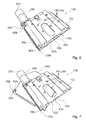
- FIG. 6 a further embodiment of the invention is shown.
- the following descriptions and the drawings are limited to Substantially to the differences between the embodiments, wherein with respect to the same designated components, in particular with respect to components with the same reference numerals, in principle also to the drawings and / or the description of the other embodiments, in particular FIGS. 1 to 5 , can be referenced.
- To distinguish the embodiments of the letter a is the reference numerals of the embodiment in the FIGS. 1 to 5 readjusted.
- the letter a is replaced by the letter b.
- FIG. 6 an alternative embodiment of the handheld power tool device 10b is shown.
- the handheld power tool device 10b corresponds in large part to the handheld power tool device 10a already described.
- the handheld power tool device 10b is designed as a handheld power tool protective hood device.
- the handheld power tool device 10b is releasably designed to be coupled to a handheld power tool 30.
- the handheld power tool device 10b forms a protective hood for the portable power tool 30.
- the portable power tool 30 is designed as a milling cutter for cutting and clearing windows from walls or masonry.
- the handheld power tool device 10b comprises at least one main body element 12b and at least one cover element 18b.
- the handheld power tool device 10b comprises a base body element 12b and a cover element 18b.
- the base body element 12b at least substantially corresponds to the base body element 12a already described.
- the base body element 12b has at least one fastening element 14b, which is provided for fastening the handheld power tool device 10b to the handheld power tool 30.
- the main body element 12b has a plurality of fastening elements 14b.
- the main body element 12b has four fastening elements 14b.
- the fastening elements 14b are each of a recess 34b formed, which are introduced into the base body member 12b.
- the main body element 12b also has a receiving area 16b, which is provided for receiving an insert tool 36 of the handheld power tool 30 in a state of the handheld power tool 10b attached to the handheld power tool 30.
- the cover element 18b corresponds at least substantially to the cover element 18a already described.
- the cover element 18b is provided to cover the receiving region 16b of the main body element 12b in an assembled state at least to a large extent. In an assembled state, the cover element 18b completely covers the receiving region 16b of the main body element 12b.
- the cover member 18b is formed of a metal sheet.
- the base member 12b and the cover 18b are at least partially pivotally coupled together ( FIG. 7 ).
- the cover member 18b is pivotally mounted relative to the base member 12b.
- the cover element 18b is pivotally mounted on the base body element 12b.
- the cover element 18b is pivotably mounted relative to the base body element 12b about an axis 24b, which is arranged at least substantially perpendicular to a contact surface 20b of the cover element 18b.
- the axis 24b is arranged perpendicular to the abutment surface 20b of the cover element 18b and in an assembled state of the handheld power tool device 10b on the handheld power tool 30 parallel to an output shaft of the handheld power tool 30, not shown.
- the output shaft of the power tool 30 and the axis 24b are arranged offset in a mounted on the power tool 30 state of the power tool apparatus 10b.
- the output shaft of the handheld power tool 30 and the axle 24b may be arranged coaxially in a state of the handheld power tool device 10b mounted on the handheld power tool 30.
- the axis 24b, around which the cover member 18b relative to the body member 12b is pivotally mounted, is disposed in an edge region of the power tool device 10b.
- the axis 24b about which the cover member 18b is pivotally supported relative to the body member 12b is located near a guide 42b corresponding to the guide 42a already described.
- the cover element 18b can be pivoted relative to the base body element 12b when the hand tool device 10b is mounted on the hand tool 30 and / or when the insertion tool 36 is changed so that the cover element 18b releases the reception area 16b.
- the basic body element 12b and the cover element 18b are connected to one another in a pivoted-up state in a captive manner.
- the cover element 12b in particular for mounting the handheld power tool device 10b on the handheld power tool 30 and / or for changing the insertion tool 36, is detachably formed by the base body element 12b.
Landscapes
- Engineering & Computer Science (AREA)
- Life Sciences & Earth Sciences (AREA)
- Mechanical Engineering (AREA)
- Wood Science & Technology (AREA)
- Forests & Forestry (AREA)
- Mining & Mineral Resources (AREA)
- Sawing (AREA)
- Grinding-Machine Dressing And Accessory Apparatuses (AREA)
Applications Claiming Priority (1)
| Application Number | Priority Date | Filing Date | Title |
|---|---|---|---|
| DE102014102859.7A DE102014102859A1 (de) | 2014-03-04 | 2014-03-04 | Handwerkzeugmaschinenvorrichtung |
Publications (1)
| Publication Number | Publication Date |
|---|---|
| EP2915639A1 true EP2915639A1 (fr) | 2015-09-09 |
Family
ID=52596402
Family Applications (1)
| Application Number | Title | Priority Date | Filing Date |
|---|---|---|---|
| EP15157191.6A Withdrawn EP2915639A1 (fr) | 2014-03-04 | 2015-03-02 | Dispositif de machines-outils |
Country Status (2)
| Country | Link |
|---|---|
| EP (1) | EP2915639A1 (fr) |
| DE (1) | DE102014102859A1 (fr) |
Cited By (5)
| Publication number | Priority date | Publication date | Assignee | Title |
|---|---|---|---|---|
| EP2937192A1 (fr) * | 2014-03-24 | 2015-10-28 | Siegfried Popp | Élément d'appui pour la partie inférieure d'un boîtier |
| EP3269508A1 (fr) * | 2016-07-15 | 2018-01-17 | HILTI Aktiengesellschaft | Capot d'aspiration pourvu d'une ouverture inclinable |
| EP3269502A1 (fr) * | 2016-07-15 | 2018-01-17 | HILTI Aktiengesellschaft | Capot d'aspiration pourvu d'une ouverture inclinable vers le haut |
| EP3269503A1 (fr) * | 2016-07-15 | 2018-01-17 | HILTI Aktiengesellschaft | Capot d'aspiration comprenant une ouverture radiale d'insertion d'outil |
| EP3659763A1 (fr) * | 2018-11-28 | 2020-06-03 | Black & Decker Inc. | Remplacement de disques de coupe rotatifs d'un outil électrique |
Families Citing this family (1)
| Publication number | Priority date | Publication date | Assignee | Title |
|---|---|---|---|---|
| DE102021121135A1 (de) | 2021-08-13 | 2023-02-16 | Eberhard Berhalter | Handwerkzeugmaschinenvorrichtung sowie Handwerkzeugmaschine mit einer Handwerkzeugmaschinenvorrichtung |
Citations (5)
| Publication number | Priority date | Publication date | Assignee | Title |
|---|---|---|---|---|
| US4913204A (en) * | 1989-09-28 | 1990-04-03 | Black & Decker Inc. | Power biscuit jointer cutter |
| US5273091A (en) * | 1991-10-21 | 1993-12-28 | Makita Corporation | Biscuit jointer |
| DE10131266A1 (de) * | 2001-06-29 | 2003-01-09 | Bosch Gmbh Robert | Handschleifmaschine |
| DE102004047277A1 (de) | 2004-09-29 | 2006-04-06 | Hilti Ag | Abdeckvorrichtung für ein Werkzeuggerät |
| DE102007011168A1 (de) | 2007-03-07 | 2008-09-11 | Mafell Ag | Handkreissäge |
-
2014
- 2014-03-04 DE DE102014102859.7A patent/DE102014102859A1/de not_active Ceased
-
2015
- 2015-03-02 EP EP15157191.6A patent/EP2915639A1/fr not_active Withdrawn
Patent Citations (5)
| Publication number | Priority date | Publication date | Assignee | Title |
|---|---|---|---|---|
| US4913204A (en) * | 1989-09-28 | 1990-04-03 | Black & Decker Inc. | Power biscuit jointer cutter |
| US5273091A (en) * | 1991-10-21 | 1993-12-28 | Makita Corporation | Biscuit jointer |
| DE10131266A1 (de) * | 2001-06-29 | 2003-01-09 | Bosch Gmbh Robert | Handschleifmaschine |
| DE102004047277A1 (de) | 2004-09-29 | 2006-04-06 | Hilti Ag | Abdeckvorrichtung für ein Werkzeuggerät |
| DE102007011168A1 (de) | 2007-03-07 | 2008-09-11 | Mafell Ag | Handkreissäge |
Cited By (9)
| Publication number | Priority date | Publication date | Assignee | Title |
|---|---|---|---|---|
| EP2937192A1 (fr) * | 2014-03-24 | 2015-10-28 | Siegfried Popp | Élément d'appui pour la partie inférieure d'un boîtier |
| EP3269508A1 (fr) * | 2016-07-15 | 2018-01-17 | HILTI Aktiengesellschaft | Capot d'aspiration pourvu d'une ouverture inclinable |
| EP3269502A1 (fr) * | 2016-07-15 | 2018-01-17 | HILTI Aktiengesellschaft | Capot d'aspiration pourvu d'une ouverture inclinable vers le haut |
| EP3269503A1 (fr) * | 2016-07-15 | 2018-01-17 | HILTI Aktiengesellschaft | Capot d'aspiration comprenant une ouverture radiale d'insertion d'outil |
| WO2018011194A1 (fr) * | 2016-07-15 | 2018-01-18 | Hilti Aktiengesellschaft | Hotte d'aspiration à ouverture pivotante |
| EP3659763A1 (fr) * | 2018-11-28 | 2020-06-03 | Black & Decker Inc. | Remplacement de disques de coupe rotatifs d'un outil électrique |
| US11440220B2 (en) | 2018-11-28 | 2022-09-13 | Black & Decker, Inc. | Replacement of rotatable cutting discs of a power tool |
| US12179386B2 (en) | 2018-11-28 | 2024-12-31 | Black & Decker, Inc. | Power tool debris management |
| EP3659764B1 (fr) * | 2018-11-28 | 2025-05-14 | Black & Decker Inc. | Gestion des débris d'un outil électrique |
Also Published As
| Publication number | Publication date |
|---|---|
| DE102014102859A1 (de) | 2015-09-10 |
Similar Documents
| Publication | Publication Date | Title |
|---|---|---|
| DE19745306C2 (de) | Handgriffanordnung für einen Winkelschleifer | |
| EP3321049B1 (fr) | Dispositif de coupe tenu à la main portable pourvu d'un assemblage de coupe | |
| EP2915639A1 (fr) | Dispositif de machines-outils | |
| DE102005063017B4 (de) | Handgeführtes Elektrowerkzeug mit einer Schutzhaube | |
| EP2965865B1 (fr) | Appareil de séparation manuel | |
| WO2003004217A1 (fr) | Dispositif de protection pour machine-outil manuelle | |
| EP3484661B1 (fr) | Capot d'aspiration pour machine-outil | |
| EP3256297B1 (fr) | Machine à tronçonner à main pourvue d'un dispositif de réglage de profondeur | |
| DE102012212803A1 (de) | Handwerkzeugzusatzhandgriff | |
| EP1714740B1 (fr) | Tronçonneuse à meule | |
| EP3173187A1 (fr) | Tronçonneuse portative manuelle | |
| WO2014000923A1 (fr) | Dispositif de séparation pour machine-outil, doté d'une unité de protection | |
| WO2021116479A1 (fr) | Machine à scier portative à main dotée d'un ensemble de pré-rainurage et d'un changement d'outil | |
| EP3209464B1 (fr) | Machine-outil portative pourvue d'un porte-outil sds | |
| EP3256298B1 (fr) | Machine à tronçonner à main pourvue d'un dispositif à ressort de rappel | |
| DE102013221566B4 (de) | Zweiteilige Schutzhaube für Trennschleifer | |
| DE19807439A1 (de) | Handwerkzeugmaschine, insbesondere Winkelschleifer | |
| DE102013210391A1 (de) | Elektrowerkzeug | |
| DE102017213747A1 (de) | Schutzvorrichtung für eine Handwerkzeugmaschine | |
| EP0429013B1 (fr) | Meuleuse d'angle avec aspiration des poussières | |
| WO2021116482A1 (fr) | Machine à scier portative mobile dotée d'un outil de rainurage sur un côté longitudinal | |
| DE102014200039A1 (de) | Handwerkzeugmaschine | |
| WO2019030010A1 (fr) | Dispositif de protection pour une machine-outil portative | |
| EP3771511B1 (fr) | Machine à fraiser à main et tambour de fraisage correspondant | |
| DE102004007764B3 (de) | Handwerkzeuggerät mit Abhängebügel |
Legal Events
| Date | Code | Title | Description |
|---|---|---|---|
| PUAI | Public reference made under article 153(3) epc to a published international application that has entered the european phase |
Free format text: ORIGINAL CODE: 0009012 |
|
| AK | Designated contracting states |
Kind code of ref document: A1 Designated state(s): AL AT BE BG CH CY CZ DE DK EE ES FI FR GB GR HR HU IE IS IT LI LT LU LV MC MK MT NL NO PL PT RO RS SE SI SK SM TR |
|
| AX | Request for extension of the european patent |
Extension state: BA ME |
|
| 17P | Request for examination filed |
Effective date: 20160226 |
|
| RBV | Designated contracting states (corrected) |
Designated state(s): AL AT BE BG CH CY CZ DE DK EE ES FI FR GB GR HR HU IE IS IT LI LT LU LV MC MK MT NL NO PL PT RO RS SE SI SK SM TR |
|
| STAA | Information on the status of an ep patent application or granted ep patent |
Free format text: STATUS: EXAMINATION IS IN PROGRESS |
|
| 17Q | First examination report despatched |
Effective date: 20170222 |
|
| GRAP | Despatch of communication of intention to grant a patent |
Free format text: ORIGINAL CODE: EPIDOSNIGR1 |
|
| STAA | Information on the status of an ep patent application or granted ep patent |
Free format text: STATUS: GRANT OF PATENT IS INTENDED |
|
| INTG | Intention to grant announced |
Effective date: 20180613 |
|
| STAA | Information on the status of an ep patent application or granted ep patent |
Free format text: STATUS: THE APPLICATION IS DEEMED TO BE WITHDRAWN |
|
| 18D | Application deemed to be withdrawn |
Effective date: 20181024 |