EP2915723A2 - Procédé de fonctionnement d'un système de direction, système de direction et véhicule - Google Patents
Procédé de fonctionnement d'un système de direction, système de direction et véhicule Download PDFInfo
- Publication number
- EP2915723A2 EP2915723A2 EP15000439.8A EP15000439A EP2915723A2 EP 2915723 A2 EP2915723 A2 EP 2915723A2 EP 15000439 A EP15000439 A EP 15000439A EP 2915723 A2 EP2915723 A2 EP 2915723A2
- Authority
- EP
- European Patent Office
- Prior art keywords
- steering wheel
- wheel
- steering
- vehicle
- driver
- Prior art date
- Legal status (The legal status is an assumption and is not a legal conclusion. Google has not performed a legal analysis and makes no representation as to the accuracy of the status listed.)
- Granted
Links
Images



Classifications
-
- B—PERFORMING OPERATIONS; TRANSPORTING
- B62—LAND VEHICLES FOR TRAVELLING OTHERWISE THAN ON RAILS
- B62D—MOTOR VEHICLES; TRAILERS
- B62D5/00—Power-assisted or power-driven steering
- B62D5/001—Mechanical components or aspects of steer-by-wire systems, not otherwise provided for in this maingroup
- B62D5/005—Mechanical components or aspects of steer-by-wire systems, not otherwise provided for in this maingroup means for generating torque on steering wheel or input member, e.g. feedback
- B62D5/006—Mechanical components or aspects of steer-by-wire systems, not otherwise provided for in this maingroup means for generating torque on steering wheel or input member, e.g. feedback power actuated
-
- B—PERFORMING OPERATIONS; TRANSPORTING
- B62—LAND VEHICLES FOR TRAVELLING OTHERWISE THAN ON RAILS
- B62D—MOTOR VEHICLES; TRAILERS
- B62D6/00—Arrangements for automatically controlling steering depending on driving conditions sensed and responded to, e.g. control circuits
- B62D6/008—Control of feed-back to the steering input member, e.g. simulating road feel in steer-by-wire applications
-
- B—PERFORMING OPERATIONS; TRANSPORTING
- B62—LAND VEHICLES FOR TRAVELLING OTHERWISE THAN ON RAILS
- B62D—MOTOR VEHICLES; TRAILERS
- B62D15/00—Steering not otherwise provided for
-
- B—PERFORMING OPERATIONS; TRANSPORTING
- B62—LAND VEHICLES FOR TRAVELLING OTHERWISE THAN ON RAILS
- B62D—MOTOR VEHICLES; TRAILERS
- B62D15/00—Steering not otherwise provided for
- B62D15/02—Steering position indicators ; Steering position determination; Steering aids
- B62D15/021—Determination of steering angle
- B62D15/0245—Means or methods for determination of the central position of the steering system, e.g. straight ahead position
-
- G—PHYSICS
- G05—CONTROLLING; REGULATING
- G05G—CONTROL DEVICES OR SYSTEMS INSOFAR AS CHARACTERISED BY MECHANICAL FEATURES ONLY
- G05G5/00—Means for preventing, limiting or returning the movements of parts of a control mechanism, e.g. locking controlling member
- G05G5/05—Means for returning or tending to return controlling members to an inoperative or neutral position, e.g. by providing return springs or resilient end-stops
Definitions
- the present invention relates to a method of operating a steering system of a vehicle, a steering system and a vehicle.
- the driver can, for example, a status screen, the total kilometer or daily mileage, signal lamps or the tank level only by turning the upper body or by manual correction of the steering wheel, which is very power-consuming in "ignition off" by omission of the power assistance is prevented by a steering wheel lock, read well.
- the view of the camera can be covered on the driver by a steering wheel. This can lead to functional limitations of the driver observation system. In particular, a video-based recognition of the driver may fail due to occlusions.
- the lower edge is flattened to facilitate entry and exit. However, if the flattened edge is not down when entering and exiting, it can not provide relief.
- a display device with a display which is controllable in order to change a representation of a display element on the display in response to a steering wheel angle of a steering wheel in order to be able to perceive the display element during cornering.
- a vehicle having a four-wheel steering system in which (all) four wheels are steerable, wherein a swivel mode is provided in which, when the vehicle is stationary, the non-driven wheels are pivoted to a position to move the vehicle about one between the driven wheels to swing the vertical axis. To determine the swing angle, the steering wheel is used. After the pivoting operation, the front wheels are returned to a neutral position.
- An object of the present invention is to avoid the disadvantages of the prior art described above, at least in some aspects.
- Another object of the present invention is to improve the ease of entry and exit when the ignition is off or when the vehicle is at a standstill.
- a first aspect of the present invention relates to a method of operating a steering system of a vehicle, wherein the steering system is a steering wheel, a steerable wheel, wherein the steerable wheel and the steering wheel are mechanically decoupled, a steering wheel actuator for setting a rotational position of the steering wheel, a Radlenkantrieb for steering the steerable wheel, and a control device for controlling the Radlenkantriebs and the steering wheel actuator has.
- the steering wheel is automatically set by the steering wheel actuator with the ignition off in a neutral position independent of a wheel steering of the steerable wheel.
- the steerable wheel and the steering wheel are independently adjustable, as described in the introduction.
- the neutral position is a position in which a clear view of the driver on predetermined areas of a combination instrument of the vehicle is possible. In other words, a line of sight between the driver and these predetermined areas, which would be hidden in other positions of the steering wheel by the steering wheel, is not obscured in the neutral position.
- the predetermined area includes a driver observation camera
- a driver recognition system using the camera can recognize the driver at the start of the vehicle, that is, the vehicle can be operational regardless of the wheel spin.
- the predetermined area includes a multifunction screen, signal lamps, status indicator, mileage indicator, fuel gauge, or the like, the driver may recognize information that may already be significant when boarding or parking the vehicle without twisting the upper body or the steering wheel manually correct with the ignition off.
- the neutral position is a position in which a flattened portion of the steering wheel comes to rest, also getting in and out can be facilitated.
- Positioning the steering wheel in the neutral position may be performed immediately after the ignition is turned off, confirmed by a driver, or by feedback from a driver-facing camera.
- a degree of automation can be increased and the driver can be relieved of encroachments and decisions.
- the driver may once again be made aware that the steering wheel is being placed in the neutral position and may also be given the opportunity to remove his hands from the steering wheel.
- a camera which is preferably positioned in the vehicle such that it is directed by the steering wheel or past the steering wheel to the driver, triggers / triggers the camera's view of the driver, in particular by the steering wheel ,
- the steering wheel can be automatically set by the steering wheel actuator when switching on the ignition in a position corresponding to a Radeinschlag the steerable wheel.
- the vehicle is brought into operational readiness in a state in which a natural steering feeling is ensured.
- the steering wheel can turn on immediately after ignition is switched on or confirmed be adjusted by a driver. In the latter case, the driver may also be given the opportunity to take sufficient time to read data of importance to him from the instrument cluster.
- the steering wheel is automatically set by a feedback of a camera directed to the driver in a position corresponding to a wheel angle of the steerable wheel.
- the steering wheel is set by the steering wheel actuator at the instigation of the driver regardless of a state of ignition in the neutral position or in a position corresponding to a Radeinschlag the steerable wheel. This can also exploit the advantages of the invention described above if the driver wishes to get on or off while the engine is running.
- a driving away of the vehicle is prevented when the steering wheel is in the neutral position and the neutral position does not correspond to a Radeinschlag the steerable wheel. This also ensures that the vehicle can only be set in motion if the driver is reliably given an accurate feedback on the steering angle.
- the invention relates in a further aspect to a steering system of a vehicle, wherein the steering system is a steering wheel, a steerable wheel, wherein the steerable wheel and the steering wheel are mechanically decoupled, a steering wheel actuator for providing a rotational position of the steering wheel, a Radlenkantrieb for steering the steerable wheel, and a controller for driving the Radlenkantriebs and the steering wheel actuator has.
- the control device is designed to operate the steering system by a method according to the above description.
- the invention relates in a further aspect to a vehicle having a steering system comprising a steering wheel, a steerable wheel, the steerable wheel and the steering wheel mechanically decoupled, a steering wheel actuator for setting a rotational position of the steering wheel, a Radlenkantrieb for steering the steerable wheel, and a control device for controlling the Radlenkantriebs and the steering wheel actuator has.
- the steering system is designed according to the above description.
- FIG. 12 shows a schematic diagram of a vehicle 100 having a steering system 1 according to an embodiment of the present invention. It should be noted that both the vehicle 100 and the steering system 1 are separate embodiments of the present invention.
- the vehicle 100 is a four-wheeled automobile, and the steering system 1 is a so-called steer-by-wire system.
- the steering system 1 has two steerable wheels 2, which are front wheels in the present embodiment.
- the steerable wheels 2 are each connected by means of a wheel suspension 3 with a support structure (not shown in detail) of the vehicle 100.
- the wheel suspensions 3 each have an electromechanical wheel steering drive 4 and a wheel steering angle sensor 5.
- a wheel steering angle RLW corresponds to a steering angle of the respective wheel 2.
- a control unit (CTR) 6 is connected via a control command line (shown in dashed lines) to the Radlenkantrieben 4 and is connected via a sensor signal line (shown dotted) with the Radlenkwinkeisensoren 5.
- the wheel suspensions 8 are connected to one another via an axle structure 9 with a stabilizing rod 10.
- a steering wheel 11 has an upper gripping area 11a, a lower gripping area 11b, a two-part transverse strut 11c and a hub 11d.
- the lower gripping area 11 e has a flattened area 11 e.
- the steering wheel 11 is connected to a steering column 12, which is mounted in a steering column bearing 13 on the support structure of the vehicle 100.
- the steering column bearing 13 has a steering wheel actuator 14 and a steering wheel angle sensor 15.
- the steering wheel actuator 14 is connected via a control command line (shown in dashed lines) and the steering wheel angle sensor 15 is connected via a sensor signal line (shown dotted) with the control unit 6.
- the controller is configured to receive and output output signals of the wheel steering angle sensors 5 and the steering wheel angle sensor 15 process and send control command signals for the wheel steering drives 4 and the steering wheel actuator 14.
- the steering system 1 is a so-called steer-by-wire system in which the steering wheel 11 is mechanically decoupled from the steerable wheels 2.
- the vehicle 100 has an instrument cluster 16 which, viewed from a driver, is arranged behind the steering wheel 11.
- the instrument cluster 16 is installed in an instrument panel (not shown in detail) of the vehicle 100.
- the instrument cluster 16 has in this embodiment, a plurality of signal lamps 17, a round instrument 18, a multi-function screen 19, a camera 20 and a status indicator 21.
- the steering wheel 11 is shown in a neutral position in which the cross member 11 c is arranged horizontally, the upper gripping portion 11 a is above, and the lower gripping portion 11 b with the flattened portion 11 e below. Since the upper gripping area 11a is at the top, a clearance between the upper gripping area 11a and the crossbar 11c provides a clear view of the instruments 17-21 of the instrument cluster 16.
- a line of sight between said areas of the instrument cluster and the eyes of one on a driver's seat 22 of the vehicle 11 seated driver is not shadowed by the steering wheel 11.
- the steering wheel 11 is rotated in a clockwise direction, first the signal lamps 17, then the round instrument 18 and the multi-function screen 19, etc. are at least partially shaded, and if the steering wheel 11 is rotated counterclockwise, first the status indicator 21, then the camera 20 and the multi-function screen 19, etc. at least partially shaded.
- the vehicle also has an ignition lock 23 for receiving an ignition key 24.
- the ignition key 24 may be an electronic or a mechanical key.
- the ignition lock 23 is connected via a signal line to the control unit 6.
- the ignition lock 23 is able to receive the ignition key 24, detect ignition positions, lock the ignition key 24 and release.
- the steerable (rear) wheels 7 are drivable by a drive 25 via a drive train 26 and a differential 27.
- the instrument cluster 16 is connected via a signal line to the control unit 6.
- control unit 6 can also be subdivided according to individual functions or arbitrarily distributed or combined.
- the control device 6 can therefore be understood in particular as a schematic placeholder for a plurality of control devices or a combination of control devices.
- the signal lines may each contain command and / or sensor signal lines which are connected to actuators and / or sensors of the respective components.
- command signals may also be signals that cause indication by the signal lamps 17, the dial 18, the multifunction display 19 or the status indicator 21, and sensor signals may also be signals, the switch operations, selection on the touch-sensitive multifunction display 19 or image signals the camera 20 be.
- the steering system 1 is operated by a method having an in FIGS. 2A . 2 B represented process 200 with in FIGS. 3 . 4 shown sub-processes 300, 400 has.
- FIGS. 2A . 2 B . 3 and 4 mentioned components 1 to 27 refer to the illustration in Fig. 1 ,
- step 201 After calling or beginning of the process 200 (step 201), it is first checked whether the key (ignition key) 24 is plugged into the ignition lock 23 or is in radio range or not. Alternatively, after calling or beginning of the process 200 (step 201), it can first be checked whether the door of the vehicle is open or unlocked. (Step 210). This check in step 210 is performed as long as the answer is "no”. If the answer in step 210 is "yes", the steering wheel 11 is set by the steering wheel actuator 14 in the neutral position (step 212 or sub-process 300, which in Fig. 3 is shown in detail and will be described later). Because in the neutral position the view between the camera 20 and the driver on the driver's seat 22, the camera can detect the driver.
- the detection result of the camera 20 is supplied to a driver identification sub-process (step 214).
- the driver identification step 214 is completed only when a driver registered for the vehicle 100 has been detected.
- the driver identification sub-process and driver registration process are not part of this invention and are therefore not further detailed.
- a personalization of the vehicle is possible. This means that if the driver is not recognized, the ignition would still be released in this case. The systems of the vehicle can then simply not be adapted to the driver.
- the ignition is released by the ignition lock 23 (step 216). Now it is checked whether the ignition has been turned on or not (step 220). This check in step 220 is performed as long as the answer is "no".
- step 230 it is further checked whether or not a driving operation by the driver has been requested. Such a request can be made, for example, via the multifunction screen 19 (touch input), a switch or a voice input. This check in step 230 is performed as long as the answer is "no”. If the answer in step 230 is "yes", the steering wheel 11 is set in the proportional position by the steering wheel actuator 14 (step 232 or sub-process 400, which is shown in FIG Fig. 4 is shown in detail and will be described later). The proportional position is a steering wheel position corresponding to a wheel steering angle of the steerable wheels 2.
- the step 230 corresponds to a request for the proportional position by the driver, which can be made for example via the multi-function screen 19, a switch or a voice input.
- the driving operation of the vehicle 100 is released (step 234), that is, the vehicle can be moved by operating the travel drive 25.
- the release of the driving operation may also involve releasing brakes.
- step 240 After release of the driving operation, it is checked whether the vehicle 100 is at a standstill or not (step 240). This check in step 240, which can be done for example by evaluation of sensor signals of the traction drive 25 or brakes or a Radwargebers is performed as long as the answer is "no". If the answer in step 240 is "yes”, it is further checked whether the ignition of the vehicle has been turned off or not (step 250). If the answer in step 240 is "yes”, first the driving is blocked (step 252), so that the vehicle can not be moved.
- the blocking of the driving operation may include, for example, a decommissioning of the traction drive 25 and / or a determination of brakes.
- a warning is issued informing the driver that the steering wheel 11 is now set in the neutral position (step 253), and it is checked whether the driver has confirmed the neutral position (step 254). Only then is the steering wheel 11 set to the neutral position (step 255 or sub-process 300), the key (ignition key) 23 is released by the ignition lock 24 (step 256) and then the operation of the vehicle is terminated (step 258). Then, the process 200 ends (step 299).
- step 250 If the answer in step 250 is "no" (ie, the ignition is not off), it is first checked whether or not a neutral position of the steering wheel 11 has been requested by the driver (step 260). If the answer in step 260 is "yes”, the driving is blocked as described above at step 252 (step 262) so that the vehicle can no longer be moved. Only then is the steering wheel 11 set by the steering wheel actuator 14 in the neutral position (step 264 or sub-process 300). Thereafter, the process returns to step 230 (FIG. Fig. 2A ) in order to release the driving operation at the request of the driver (cf the description above).
- This process path via steps 250, 260, 262, 264 makes it possible for the driver to be able to leave the vehicle even when the ignition is switched on, and nevertheless the steering wheel 11 can be set to the neutral position.
- step 260 If the answer in step 260 is "no" (ie no neutral position requested), the process returns to step 240 to check if the vehicle is at a standstill. In other words, steps 240, 250 and 260 form a loop that is exited only when the answer in step 250 or 260 is "yes". The entire process 200 is terminated only if the answer in step 250 "yes" is. It is understood that after the operation is completed in step 299, a standby mode may be activated, which may coincide with a restart of the process 200 (step 201).
- a warning is issued and a confirmation of the driver is awaited. This ensures that the driver is aware of the upcoming adjustment of the steering wheel 11. Instead of a confirmation, only the warning can be issued.
- the warning may be output via one of the signal lamps 17, the multifunction screen 19, the status indicator 21 or in some other way, such as acoustically.
- the confirmation may be given via the multifunction screen 19 or otherwise, such as a voice input switch.
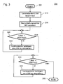
- the sub-process 300 which is performed in steps 212, 255 or 264 to set the steering wheel 11 in the neutral position, will be described below with reference to the flowchart in FIG Fig. 3 described.
- the steering wheel angle LRW is first determined (step 312). Thereafter, the neutral position angle NW corresponding to the neutral position of the steering wheel 11 is read out from a memory of the controller 6 (step 314).
- the neutral position angle NW will be zero degrees, but the invention is not limited thereto.
- the neutral position angle NW can also correspond to a certain inclination of the steering wheel 11, if then the view of the instrument cluster 16 or a selected area thereof is better. Then, it is checked whether or not the steering wheel angle LRW is greater than the neutral position angle NW plus a tolerance Tol (step 320).
- step 320 If the answer is "NO” in step 320, it is checked whether or not the steering wheel angle LRW is smaller than the neutral position angle NW minus the tolerance Tol (step 330). If the answer in step 330 is "no", the sub-process 300 ends (step 399) because the steering wheel angle LRW is obviously equal to the neutral position angle NW within the predetermined tolerance ⁇ Tol.
- step 320 If the answer in step 320 is "yes”, the steering wheel actuator 14 is operated to decrease the steering wheel angle LRW (step 322). This is repeated until the steering wheel angle LRW corresponds at most to the neutral position angle NW plus the tolerance Tol. Then, the answer in step 320 is "no”, and the process goes to step 330 ("no" because the steering wheel angle LRW is now within the tolerance range ⁇ Tol about the neutral position angle NW) to step 399, thereby terminating the sub-process 300.
- step 330 If the answer in step 330 is "yes”, the steering wheel actuator 14 is operated to increase the steering wheel angle LRW (step 332). This is repeated until the steering wheel angle LRW is at least equal to the neutral position angle NW minus the tolerance Tol. Then, the answer in step 330 is "no", and the process goes to step 399, whereby the sub-process 300 ends.
- step 232 The sub-process 400 performed in step 232 to set the steering wheel 11 in the proportional position will be described below with reference to the flowchart in FIG Fig. 4 described.
- the steering wheel angle LRW is first determined (step 412). Thereafter, the wheel steering angle RLW corresponding to a wheel turning of the steerable wheels 2 is determined from an output of the wheel steering angle sensor 5 (step 414). From the wheel steering angle RLW, the proportional angle PW is then calculated as that angle of the steering wheel 11 which corresponds to the wheel steering angle RLW. Then, it is checked whether or not the steering wheel angle LRW is greater than the proportional angle PW plus a tolerance Tol (step 420). If the answer is "NO” in step 420, it is checked whether or not the steering wheel angle LRW is smaller than the proportional angle PW minus the tolerance Tol (step 430). If the answer in step 430 is "no", the sub-process 400 ends (step 499) because the steering wheel angle LRW is obviously equal to the proportional angle PW within the predetermined tolerance ⁇ Tol.
- step 420 If the answer in step 420 is "yes”, the steering wheel actuator 14 is operated to decrease the steering wheel angle LRW (step 422). This is repeated for so long until the steering wheel angle LRW corresponds at most to the proportional angle PW plus the tolerance Tol. Then, the answer in step 420 is "no”, and the process goes to step 430 ("no" because the steering wheel angle LRW is now within the tolerance range ⁇ Tol about the proportional angle PW) to step 499, terminating the subprocess 400.
- step 430 If the answer is "yes” in step 430, the steering wheel actuator 14 is operated to increase the steering wheel angle LRW (step 432). This is repeated until the steering wheel angle LRW at least equal to the proportional angle PW minus the tolerance Tol. Then, the answer in step 430 is "no", and the process proceeds to step 499, whereby the sub-process 400 ends.
- the tolerance Tol in the subprocesses 300, 400 may be different, and may be different in the positive and negative directions.
- the process 200 with subprocesses 300, 400 described above corresponds to a method for operating the steering system 1 and is controlled by the control unit 6.
- the steerable wheels 2 are each steerable with their own individually controllable wheel steering drive 4.
- the invention is not limited thereto. Rather, the steerable wheels 2 may have a common Radlenkantrieb 4, which acts on both suspensions 3, for example via a rack and pinion mechanism.
- the invention is not limited to steerable front wheels. Rather, the rear wheels of the vehicle 100 may also be (additionally or only) steerable wheels.
- the invention is not limited to four-wheeled vehicles with two or four steerable wheels. Rather, the invention is also applicable to vehicles having two, three, five or more wheels, any number of which may be steerable.
- the use of the singular is to be understood not only in the exclusive, but also in the simply ascertaining sense. So for example, when it is said that the vehicle has a steerable wheel, the disclosure and scope are not limited to a single steerable wheel structure. Rather, it should be expressed only that the vehicle (at least) has a steerable wheel, but may also have multiple steerable wheels.
Landscapes
- Engineering & Computer Science (AREA)
- Chemical & Material Sciences (AREA)
- Combustion & Propulsion (AREA)
- Transportation (AREA)
- Mechanical Engineering (AREA)
- Physics & Mathematics (AREA)
- General Physics & Mathematics (AREA)
- Automation & Control Theory (AREA)
- Steering Control In Accordance With Driving Conditions (AREA)
- Steering Controls (AREA)
Applications Claiming Priority (1)
| Application Number | Priority Date | Filing Date | Title |
|---|---|---|---|
| DE102014003302.3A DE102014003302B3 (de) | 2014-03-08 | 2014-03-08 | Verfahren zum Betreiben eines Lenksystems, Lenksystem und Fahrzeug |
Publications (3)
| Publication Number | Publication Date |
|---|---|
| EP2915723A2 true EP2915723A2 (fr) | 2015-09-09 |
| EP2915723A3 EP2915723A3 (fr) | 2016-05-04 |
| EP2915723B1 EP2915723B1 (fr) | 2017-12-27 |
Family
ID=52577591
Family Applications (1)
| Application Number | Title | Priority Date | Filing Date |
|---|---|---|---|
| EP15000439.8A Active EP2915723B1 (fr) | 2014-03-08 | 2015-02-13 | Procédé de fonctionnement d'un système de direction, système de direction et véhicule |
Country Status (4)
| Country | Link |
|---|---|
| US (1) | US9637163B2 (fr) |
| EP (1) | EP2915723B1 (fr) |
| CN (1) | CN104890726B (fr) |
| DE (1) | DE102014003302B3 (fr) |
Cited By (2)
| Publication number | Priority date | Publication date | Assignee | Title |
|---|---|---|---|---|
| WO2022185397A1 (fr) * | 2021-03-02 | 2022-09-09 | Honda Motor Co., Ltd. | Système de direction pour véhicule |
| WO2024120681A1 (fr) * | 2022-12-05 | 2024-06-13 | Mercedes-Benz Group AG | Procédé de fonctionnement d'un dispositif de direction à commande électrique pour un véhicule à moteur |
Families Citing this family (15)
| Publication number | Priority date | Publication date | Assignee | Title |
|---|---|---|---|---|
| DE102016015155A1 (de) * | 2016-05-13 | 2017-11-16 | Liebherr-Werk Bischofshofen Gmbh | Anordnung zum Steuern einer Arbeitsmaschine |
| JP6270250B1 (ja) | 2016-09-21 | 2018-01-31 | マツダ株式会社 | 車両用挙動制御装置 |
| US10822017B2 (en) | 2016-10-17 | 2020-11-03 | Agjunction Llc | Integrated auto-steer system for vehicle |
| JP6528787B2 (ja) * | 2017-01-17 | 2019-06-12 | トヨタ自動車株式会社 | 車両の制御装置 |
| DE102017201357A1 (de) | 2017-01-27 | 2018-08-02 | Ford Global Technologies, Llc | Steuerverfahren für ein Kraftfahrzeug-Lenksystem |
| JP6687569B2 (ja) * | 2017-07-31 | 2020-04-22 | 矢崎総業株式会社 | 車両用照明装置 |
| JP2019104450A (ja) * | 2017-12-14 | 2019-06-27 | 矢崎総業株式会社 | 車載撮影装置、及び車載撮影方法 |
| CN108394459B (zh) * | 2018-02-07 | 2019-12-10 | 北京汽车股份有限公司 | 车辆的转向控制方法、系统及车辆 |
| US20190375446A1 (en) * | 2018-06-07 | 2019-12-12 | GM Global Technology Operations LLC | Systems and methods for steering wheel alignment and motion control |
| CN110654457A (zh) * | 2018-06-29 | 2020-01-07 | 比亚迪股份有限公司 | 车辆以及车辆的转向控制系统和方法、装置 |
| AU2020320351B2 (en) * | 2019-07-31 | 2025-10-09 | Agjunction Llc | Integrated vehicle guidance and steering system |
| JP7284690B2 (ja) * | 2019-11-11 | 2023-05-31 | 株式会社デンソー | モータ駆動システム |
| CN113830173B (zh) * | 2021-09-27 | 2023-05-23 | 重庆长安新能源汽车科技有限公司 | 一种方向盘控制方法及系统 |
| JP7553418B2 (ja) | 2021-09-30 | 2024-09-18 | 本田技研工業株式会社 | 車両 |
| CN114802443A (zh) * | 2022-05-09 | 2022-07-29 | 一汽解放汽车有限公司 | 方向盘校正系统、控制方法、方向盘组件以及车辆 |
Citations (3)
| Publication number | Priority date | Publication date | Assignee | Title |
|---|---|---|---|---|
| DE10034291A1 (de) | 1999-07-15 | 2001-02-01 | Honda Motor Co Ltd | Fahrzeug mit Schwenkmechanismus |
| JP2012040977A (ja) | 2010-08-20 | 2012-03-01 | Suzuki Motor Corp | 駐車支援システム |
| DE102012005674A1 (de) | 2012-03-21 | 2013-04-18 | Daimler Ag | Anzeigevorrichtung und Verfahren zum lenkwinkelabhängigen Darstellen von Informationen |
Family Cites Families (7)
| Publication number | Priority date | Publication date | Assignee | Title |
|---|---|---|---|---|
| DE19601827B4 (de) | 1996-01-19 | 2006-10-26 | Robert Bosch Gmbh | Lenksystem für ein Kraftfahrzeug |
| JP3635365B2 (ja) * | 1999-03-31 | 2005-04-06 | 光洋精工株式会社 | 車両用操舵装置 |
| DE10151010A1 (de) * | 2001-10-16 | 2003-04-17 | Volkswagen Ag | Kraftfahrzeug mit einer Lenkradverriegelung |
| JP4746350B2 (ja) * | 2005-05-20 | 2011-08-10 | 株式会社東海理化電機製作所 | 操舵装置 |
| US9041789B2 (en) * | 2011-03-25 | 2015-05-26 | Tk Holdings Inc. | System and method for determining driver alertness |
| JP5692049B2 (ja) * | 2011-12-26 | 2015-04-01 | 株式会社デンソー | ステアリング位置制御システム |
| US8666601B1 (en) * | 2013-04-25 | 2014-03-04 | Ford Global Technologies, Llc | Visibility of a vehicle ignition location |
-
2014
- 2014-03-08 DE DE102014003302.3A patent/DE102014003302B3/de not_active Expired - Fee Related
-
2015
- 2015-02-13 EP EP15000439.8A patent/EP2915723B1/fr active Active
- 2015-03-04 US US14/638,777 patent/US9637163B2/en active Active
- 2015-03-06 CN CN201510100370.7A patent/CN104890726B/zh active Active
Patent Citations (3)
| Publication number | Priority date | Publication date | Assignee | Title |
|---|---|---|---|---|
| DE10034291A1 (de) | 1999-07-15 | 2001-02-01 | Honda Motor Co Ltd | Fahrzeug mit Schwenkmechanismus |
| JP2012040977A (ja) | 2010-08-20 | 2012-03-01 | Suzuki Motor Corp | 駐車支援システム |
| DE102012005674A1 (de) | 2012-03-21 | 2013-04-18 | Daimler Ag | Anzeigevorrichtung und Verfahren zum lenkwinkelabhängigen Darstellen von Informationen |
Cited By (5)
| Publication number | Priority date | Publication date | Assignee | Title |
|---|---|---|---|---|
| WO2022185397A1 (fr) * | 2021-03-02 | 2022-09-09 | Honda Motor Co., Ltd. | Système de direction pour véhicule |
| CN115803248A (zh) * | 2021-03-02 | 2023-03-14 | 本田技研工业株式会社 | 用于车辆的转向系统 |
| US12258080B2 (en) | 2021-03-02 | 2025-03-25 | Honda Motor Co., Ltd. | Steering system for vehicle |
| CN115803248B (zh) * | 2021-03-02 | 2026-03-24 | 本田技研工业株式会社 | 用于车辆的转向系统 |
| WO2024120681A1 (fr) * | 2022-12-05 | 2024-06-13 | Mercedes-Benz Group AG | Procédé de fonctionnement d'un dispositif de direction à commande électrique pour un véhicule à moteur |
Also Published As
| Publication number | Publication date |
|---|---|
| CN104890726A (zh) | 2015-09-09 |
| US20150251688A1 (en) | 2015-09-10 |
| DE102014003302B3 (de) | 2015-06-11 |
| EP2915723B1 (fr) | 2017-12-27 |
| US9637163B2 (en) | 2017-05-02 |
| EP2915723A3 (fr) | 2016-05-04 |
| CN104890726B (zh) | 2017-09-15 |
Similar Documents
| Publication | Publication Date | Title |
|---|---|---|
| EP2915723B1 (fr) | Procédé de fonctionnement d'un système de direction, système de direction et véhicule | |
| DE102006048947B4 (de) | Steuereinheit und Verfahren zum Verstellen eines an ein Fahrzeug angekuppelten Anhängers | |
| EP3956167B1 (fr) | Procédé d'exécution d'une correction de la direction de déplacement par un système d'aide à la conduite dans un véhicule à moteur ainsi que dispositif de commande à cet effet | |
| DE102014115334B4 (de) | Verfahren zum Unterstützen eines Fahrers eines Kraftfahrzeugs beim Einparken in eine Parklücke, Fahrerassistenzsystem sowie Kraftfahrzeug | |
| DE102005037468A1 (de) | Vorrichtung und Verfahren zur Unterstützung eines Einparkvorgangs eines Fahrzeugs | |
| DE102008003666A1 (de) | Verfahren für die Steuerung eines Fahrerassistenzsystems und Fahrerassistenzsystem | |
| WO2014166685A1 (fr) | Dispositif d'affichage et procédé d'affichage de données et système d'aide à la conduite pour un véhicule | |
| DE102021206404B4 (de) | Verfahren und system zur lenkungssteuerung während fahrzeugrückfahrbetriebs zum manövrieren eines anhängers | |
| DE102010028109A1 (de) | Verfahren zur Verbesserung der Fahrstabilität eines Fahrzeugs | |
| DE102016116913A1 (de) | Multifunktionsneigungsschalter für Parkfunktion | |
| DE102016115132A1 (de) | Unterstützung eines Fahrers eines Kraftfahrzeugs mit einem angehängten Anhänger beim Einparken durch virtuelle Sensoren | |
| DE112019006043T5 (de) | Parkassistenzvorrichtung | |
| WO2015192987A1 (fr) | Procédé d'assistance à la conduite lors de la surveillance de la marche d'un véhicule à moteur ou d'un ensemble routier | |
| DE102004027250A1 (de) | Verfahren und Vorrichtung zum unterstützten Steuern eines Kraftfahrzeuges | |
| DE102019111477A1 (de) | Verfahren zum Ausparken eines Fahrzeugs von einem Bordstein | |
| WO2020193490A1 (fr) | Procédé et système d'aide à la conduite pour aider un conducteur d'un véhicule lors d'une manœuvre de stationnement dans une place de stationnement en créneau | |
| DE102014118719A1 (de) | Fahrtunterstützungssystem | |
| DE102018215265B4 (de) | Verfahren und Steuereinrichtung zum Betreiben einer am Kopf tragbaren Anzeigeeinrichtung in einem Kraftfahrzeug | |
| DE102023002351A1 (de) | Verfahren zur Durchführung einer prädiktiven Lenksteuerung sowie Steer-by-Wire-Lenksystem | |
| DE102022118490A1 (de) | Verfahren zum Betreiben eines Spurführungsassistenten eines Fahrzeugs unter Berücksichtigung von Fahrereingriffen, Spurführungsassistent sowie Fahrzeug | |
| DE102010054222B4 (de) | Einstellen eines Fahrwerks eines Kraftfahrzeugs | |
| DE102013015027A1 (de) | Verfahren zum Betreiben eines Lenkhilfesystems eines Kraftfahrzeugs | |
| DE102022113810A1 (de) | Verfahren und vorrichtung zum steuern eines automatisierten kraftfahrzeugs | |
| DE102010040437A1 (de) | Fahrunterstützungseinrichtung | |
| DE102016111878A1 (de) | Verfahren zum Bestimmen einer Ausrichtung eines auf einer Parkfläche geparkten Kraftfahrzeugs, Steuergerät, Fahrerassistenzsystem sowie Kraftfahrzeug |
Legal Events
| Date | Code | Title | Description |
|---|---|---|---|
| PUAI | Public reference made under article 153(3) epc to a published international application that has entered the european phase |
Free format text: ORIGINAL CODE: 0009012 |
|
| AK | Designated contracting states |
Kind code of ref document: A2 Designated state(s): AL AT BE BG CH CY CZ DE DK EE ES FI FR GB GR HR HU IE IS IT LI LT LU LV MC MK MT NL NO PL PT RO RS SE SI SK SM TR |
|
| AX | Request for extension of the european patent |
Extension state: BA ME |
|
| PUAL | Search report despatched |
Free format text: ORIGINAL CODE: 0009013 |
|
| AK | Designated contracting states |
Kind code of ref document: A3 Designated state(s): AL AT BE BG CH CY CZ DE DK EE ES FI FR GB GR HR HU IE IS IT LI LT LU LV MC MK MT NL NO PL PT RO RS SE SI SK SM TR |
|
| AX | Request for extension of the european patent |
Extension state: BA ME |
|
| RIC1 | Information provided on ipc code assigned before grant |
Ipc: B62D 15/00 20060101AFI20160330BHEP Ipc: B60R 1/00 20060101ALI20160330BHEP |
|
| 17P | Request for examination filed |
Effective date: 20161104 |
|
| RBV | Designated contracting states (corrected) |
Designated state(s): AL AT BE BG CH CY CZ DE DK EE ES FI FR GB GR HR HU IE IS IT LI LT LU LV MC MK MT NL NO PL PT RO RS SE SI SK SM TR |
|
| GRAP | Despatch of communication of intention to grant a patent |
Free format text: ORIGINAL CODE: EPIDOSNIGR1 |
|
| INTG | Intention to grant announced |
Effective date: 20170811 |
|
| GRAJ | Information related to disapproval of communication of intention to grant by the applicant or resumption of examination proceedings by the epo deleted |
Free format text: ORIGINAL CODE: EPIDOSDIGR1 |
|
| GRAP | Despatch of communication of intention to grant a patent |
Free format text: ORIGINAL CODE: EPIDOSNIGR1 |
|
| INTC | Intention to grant announced (deleted) | ||
| INTG | Intention to grant announced |
Effective date: 20170928 |
|
| GRAS | Grant fee paid |
Free format text: ORIGINAL CODE: EPIDOSNIGR3 |
|
| GRAA | (expected) grant |
Free format text: ORIGINAL CODE: 0009210 |
|
| AK | Designated contracting states |
Kind code of ref document: B1 Designated state(s): AL AT BE BG CH CY CZ DE DK EE ES FI FR GB GR HR HU IE IS IT LI LT LU LV MC MK MT NL NO PL PT RO RS SE SI SK SM TR |
|
| REG | Reference to a national code |
Ref country code: GB Ref legal event code: FG4D Free format text: NOT ENGLISH |
|
| REG | Reference to a national code |
Ref country code: CH Ref legal event code: EP |
|
| REG | Reference to a national code |
Ref country code: AT Ref legal event code: REF Ref document number: 958017 Country of ref document: AT Kind code of ref document: T Effective date: 20180115 |
|
| REG | Reference to a national code |
Ref country code: IE Ref legal event code: FG4D Free format text: LANGUAGE OF EP DOCUMENT: GERMAN |
|
| REG | Reference to a national code |
Ref country code: DE Ref legal event code: R096 Ref document number: 502015002655 Country of ref document: DE |
|
| REG | Reference to a national code |
Ref country code: FR Ref legal event code: PLFP Year of fee payment: 4 |
|
| PG25 | Lapsed in a contracting state [announced via postgrant information from national office to epo] |
Ref country code: LT Free format text: LAPSE BECAUSE OF FAILURE TO SUBMIT A TRANSLATION OF THE DESCRIPTION OR TO PAY THE FEE WITHIN THE PRESCRIBED TIME-LIMIT Effective date: 20171227 Ref country code: FI Free format text: LAPSE BECAUSE OF FAILURE TO SUBMIT A TRANSLATION OF THE DESCRIPTION OR TO PAY THE FEE WITHIN THE PRESCRIBED TIME-LIMIT Effective date: 20171227 Ref country code: NO Free format text: LAPSE BECAUSE OF FAILURE TO SUBMIT A TRANSLATION OF THE DESCRIPTION OR TO PAY THE FEE WITHIN THE PRESCRIBED TIME-LIMIT Effective date: 20180327 |
|
| REG | Reference to a national code |
Ref country code: NL Ref legal event code: MP Effective date: 20171227 |
|
| REG | Reference to a national code |
Ref country code: LT Ref legal event code: MG4D |
|
| PG25 | Lapsed in a contracting state [announced via postgrant information from national office to epo] |
Ref country code: LV Free format text: LAPSE BECAUSE OF FAILURE TO SUBMIT A TRANSLATION OF THE DESCRIPTION OR TO PAY THE FEE WITHIN THE PRESCRIBED TIME-LIMIT Effective date: 20171227 Ref country code: RS Free format text: LAPSE BECAUSE OF FAILURE TO SUBMIT A TRANSLATION OF THE DESCRIPTION OR TO PAY THE FEE WITHIN THE PRESCRIBED TIME-LIMIT Effective date: 20171227 Ref country code: GR Free format text: LAPSE BECAUSE OF FAILURE TO SUBMIT A TRANSLATION OF THE DESCRIPTION OR TO PAY THE FEE WITHIN THE PRESCRIBED TIME-LIMIT Effective date: 20180328 Ref country code: BG Free format text: LAPSE BECAUSE OF FAILURE TO SUBMIT A TRANSLATION OF THE DESCRIPTION OR TO PAY THE FEE WITHIN THE PRESCRIBED TIME-LIMIT Effective date: 20180327 Ref country code: HR Free format text: LAPSE BECAUSE OF FAILURE TO SUBMIT A TRANSLATION OF THE DESCRIPTION OR TO PAY THE FEE WITHIN THE PRESCRIBED TIME-LIMIT Effective date: 20171227 |
|
| PG25 | Lapsed in a contracting state [announced via postgrant information from national office to epo] |
Ref country code: NL Free format text: LAPSE BECAUSE OF FAILURE TO SUBMIT A TRANSLATION OF THE DESCRIPTION OR TO PAY THE FEE WITHIN THE PRESCRIBED TIME-LIMIT Effective date: 20171227 |
|
| PG25 | Lapsed in a contracting state [announced via postgrant information from national office to epo] |
Ref country code: ES Free format text: LAPSE BECAUSE OF FAILURE TO SUBMIT A TRANSLATION OF THE DESCRIPTION OR TO PAY THE FEE WITHIN THE PRESCRIBED TIME-LIMIT Effective date: 20171227 Ref country code: SK Free format text: LAPSE BECAUSE OF FAILURE TO SUBMIT A TRANSLATION OF THE DESCRIPTION OR TO PAY THE FEE WITHIN THE PRESCRIBED TIME-LIMIT Effective date: 20171227 Ref country code: CZ Free format text: LAPSE BECAUSE OF FAILURE TO SUBMIT A TRANSLATION OF THE DESCRIPTION OR TO PAY THE FEE WITHIN THE PRESCRIBED TIME-LIMIT Effective date: 20171227 Ref country code: EE Free format text: LAPSE BECAUSE OF FAILURE TO SUBMIT A TRANSLATION OF THE DESCRIPTION OR TO PAY THE FEE WITHIN THE PRESCRIBED TIME-LIMIT Effective date: 20171227 Ref country code: CY Free format text: LAPSE BECAUSE OF FAILURE TO SUBMIT A TRANSLATION OF THE DESCRIPTION OR TO PAY THE FEE WITHIN THE PRESCRIBED TIME-LIMIT Effective date: 20171227 |
|
| PG25 | Lapsed in a contracting state [announced via postgrant information from national office to epo] |
Ref country code: PL Free format text: LAPSE BECAUSE OF FAILURE TO SUBMIT A TRANSLATION OF THE DESCRIPTION OR TO PAY THE FEE WITHIN THE PRESCRIBED TIME-LIMIT Effective date: 20171227 Ref country code: IS Free format text: LAPSE BECAUSE OF FAILURE TO SUBMIT A TRANSLATION OF THE DESCRIPTION OR TO PAY THE FEE WITHIN THE PRESCRIBED TIME-LIMIT Effective date: 20180427 Ref country code: RO Free format text: LAPSE BECAUSE OF FAILURE TO SUBMIT A TRANSLATION OF THE DESCRIPTION OR TO PAY THE FEE WITHIN THE PRESCRIBED TIME-LIMIT Effective date: 20171227 Ref country code: IT Free format text: LAPSE BECAUSE OF FAILURE TO SUBMIT A TRANSLATION OF THE DESCRIPTION OR TO PAY THE FEE WITHIN THE PRESCRIBED TIME-LIMIT Effective date: 20171227 Ref country code: SM Free format text: LAPSE BECAUSE OF FAILURE TO SUBMIT A TRANSLATION OF THE DESCRIPTION OR TO PAY THE FEE WITHIN THE PRESCRIBED TIME-LIMIT Effective date: 20171227 |
|
| REG | Reference to a national code |
Ref country code: CH Ref legal event code: PL |
|
| PG25 | Lapsed in a contracting state [announced via postgrant information from national office to epo] |
Ref country code: MC Free format text: LAPSE BECAUSE OF FAILURE TO SUBMIT A TRANSLATION OF THE DESCRIPTION OR TO PAY THE FEE WITHIN THE PRESCRIBED TIME-LIMIT Effective date: 20171227 Ref country code: MT Free format text: LAPSE BECAUSE OF FAILURE TO SUBMIT A TRANSLATION OF THE DESCRIPTION OR TO PAY THE FEE WITHIN THE PRESCRIBED TIME-LIMIT Effective date: 20171227 |
|
| REG | Reference to a national code |
Ref country code: DE Ref legal event code: R097 Ref document number: 502015002655 Country of ref document: DE |
|
| PLBE | No opposition filed within time limit |
Free format text: ORIGINAL CODE: 0009261 |
|
| STAA | Information on the status of an ep patent application or granted ep patent |
Free format text: STATUS: NO OPPOSITION FILED WITHIN TIME LIMIT |
|
| REG | Reference to a national code |
Ref country code: IE Ref legal event code: MM4A |
|
| REG | Reference to a national code |
Ref country code: BE Ref legal event code: MM Effective date: 20180228 |
|
| PG25 | Lapsed in a contracting state [announced via postgrant information from national office to epo] |
Ref country code: CH Free format text: LAPSE BECAUSE OF NON-PAYMENT OF DUE FEES Effective date: 20180228 Ref country code: LU Free format text: LAPSE BECAUSE OF NON-PAYMENT OF DUE FEES Effective date: 20180213 Ref country code: LI Free format text: LAPSE BECAUSE OF NON-PAYMENT OF DUE FEES Effective date: 20180228 Ref country code: DK Free format text: LAPSE BECAUSE OF FAILURE TO SUBMIT A TRANSLATION OF THE DESCRIPTION OR TO PAY THE FEE WITHIN THE PRESCRIBED TIME-LIMIT Effective date: 20171227 |
|
| 26N | No opposition filed |
Effective date: 20180928 |
|
| PG25 | Lapsed in a contracting state [announced via postgrant information from national office to epo] |
Ref country code: IE Free format text: LAPSE BECAUSE OF NON-PAYMENT OF DUE FEES Effective date: 20180213 |
|
| PG25 | Lapsed in a contracting state [announced via postgrant information from national office to epo] |
Ref country code: BE Free format text: LAPSE BECAUSE OF NON-PAYMENT OF DUE FEES Effective date: 20180228 Ref country code: SI Free format text: LAPSE BECAUSE OF FAILURE TO SUBMIT A TRANSLATION OF THE DESCRIPTION OR TO PAY THE FEE WITHIN THE PRESCRIBED TIME-LIMIT Effective date: 20171227 |
|
| PG25 | Lapsed in a contracting state [announced via postgrant information from national office to epo] |
Ref country code: TR Free format text: LAPSE BECAUSE OF FAILURE TO SUBMIT A TRANSLATION OF THE DESCRIPTION OR TO PAY THE FEE WITHIN THE PRESCRIBED TIME-LIMIT Effective date: 20171227 |
|
| PG25 | Lapsed in a contracting state [announced via postgrant information from national office to epo] |
Ref country code: PT Free format text: LAPSE BECAUSE OF FAILURE TO SUBMIT A TRANSLATION OF THE DESCRIPTION OR TO PAY THE FEE WITHIN THE PRESCRIBED TIME-LIMIT Effective date: 20171227 |
|
| PG25 | Lapsed in a contracting state [announced via postgrant information from national office to epo] |
Ref country code: HU Free format text: LAPSE BECAUSE OF FAILURE TO SUBMIT A TRANSLATION OF THE DESCRIPTION OR TO PAY THE FEE WITHIN THE PRESCRIBED TIME-LIMIT; INVALID AB INITIO Effective date: 20150213 Ref country code: MK Free format text: LAPSE BECAUSE OF NON-PAYMENT OF DUE FEES Effective date: 20171227 Ref country code: SE Free format text: LAPSE BECAUSE OF FAILURE TO SUBMIT A TRANSLATION OF THE DESCRIPTION OR TO PAY THE FEE WITHIN THE PRESCRIBED TIME-LIMIT Effective date: 20171227 |
|
| PG25 | Lapsed in a contracting state [announced via postgrant information from national office to epo] |
Ref country code: AL Free format text: LAPSE BECAUSE OF FAILURE TO SUBMIT A TRANSLATION OF THE DESCRIPTION OR TO PAY THE FEE WITHIN THE PRESCRIBED TIME-LIMIT Effective date: 20171227 |
|
| REG | Reference to a national code |
Ref country code: AT Ref legal event code: MM01 Ref document number: 958017 Country of ref document: AT Kind code of ref document: T Effective date: 20200213 |
|
| PG25 | Lapsed in a contracting state [announced via postgrant information from national office to epo] |
Ref country code: AT Free format text: LAPSE BECAUSE OF NON-PAYMENT OF DUE FEES Effective date: 20200213 |
|
| P01 | Opt-out of the competence of the unified patent court (upc) registered |
Effective date: 20230530 |
|
| PGFP | Annual fee paid to national office [announced via postgrant information from national office to epo] |
Ref country code: GB Payment date: 20260219 Year of fee payment: 12 |
|
| PGFP | Annual fee paid to national office [announced via postgrant information from national office to epo] |
Ref country code: DE Payment date: 20260228 Year of fee payment: 12 |
|
| PGFP | Annual fee paid to national office [announced via postgrant information from national office to epo] |
Ref country code: FR Payment date: 20260219 Year of fee payment: 12 |