EP2915751B1 - Schlauch- und Fangtrichterverfahren zur Betankung während des Fluges mit verbesserter Steuerung der Schlauch- und Fangtrichterbewegung - Google Patents
Schlauch- und Fangtrichterverfahren zur Betankung während des Fluges mit verbesserter Steuerung der Schlauch- und Fangtrichterbewegung Download PDFInfo
- Publication number
- EP2915751B1 EP2915751B1 EP14382082.7A EP14382082A EP2915751B1 EP 2915751 B1 EP2915751 B1 EP 2915751B1 EP 14382082 A EP14382082 A EP 14382082A EP 2915751 B1 EP2915751 B1 EP 2915751B1
- Authority
- EP
- European Patent Office
- Prior art keywords
- hose
- drogue
- tension
- refueling
- receiver
- Prior art date
- Legal status (The legal status is an assumption and is not a legal conclusion. Google has not performed a legal analysis and makes no representation as to the accuracy of the status listed.)
- Active
Links
Images


Classifications
-
- B—PERFORMING OPERATIONS; TRANSPORTING
- B64—AIRCRAFT; AVIATION; COSMONAUTICS
- B64D—EQUIPMENT FOR FITTING IN OR TO AIRCRAFT; FLIGHT SUITS; PARACHUTES; ARRANGEMENT OR MOUNTING OF POWER PLANTS OR PROPULSION TRANSMISSIONS IN AIRCRAFT
- B64D39/00—Refuelling during flight
- B64D39/06—Connecting hose to aircraft; Disconnecting hose therefrom
-
- B—PERFORMING OPERATIONS; TRANSPORTING
- B64—AIRCRAFT; AVIATION; COSMONAUTICS
- B64D—EQUIPMENT FOR FITTING IN OR TO AIRCRAFT; FLIGHT SUITS; PARACHUTES; ARRANGEMENT OR MOUNTING OF POWER PLANTS OR PROPULSION TRANSMISSIONS IN AIRCRAFT
- B64D39/00—Refuelling during flight
-
- B—PERFORMING OPERATIONS; TRANSPORTING
- B64—AIRCRAFT; AVIATION; COSMONAUTICS
- B64D—EQUIPMENT FOR FITTING IN OR TO AIRCRAFT; FLIGHT SUITS; PARACHUTES; ARRANGEMENT OR MOUNTING OF POWER PLANTS OR PROPULSION TRANSMISSIONS IN AIRCRAFT
- B64D39/00—Refuelling during flight
- B64D39/02—Means for paying-in or out hose
Definitions
- the present invention relates to hose&drogue in-flight refueling method and systems and more in particular to the control of the hose&drogue device motion.
- a known system for performing in-flight refueling operations is based on a refueling device 15 allowing fuel to pass from a tanker aircraft 13 to a receiver aircraft 11.
- the refueling device 15 comprises a hose&drogue device 17 in the tanker aircraft 13 and a probe 25 in the receiver aircraft 11.
- the hose&drogue device 17 comprises a flexible hose 19 that trails from a refueling unit (pod or FRU) located in the tanker aircraft 13, a reception coupling unit 23 at the end of the hose 19 which has a passage for receiving the nozzle of the probe 25, and a drogue 21 which is a fitting resembling a windsock or shuttlecock that is used to stabilise the hose 19 trailing from the tanker aircraft 13 and to provide the drag to maintain the hose catenary and the mating force with the probe 25.
- a refueling unit pod or FRU
- the hose&drogue device 17 is extended/retracted from/to a drum device 35 that includes a winding drum for extending/retracting the hose 19 and a motor to actuate the winding drum. When not in use the hose 19 is reeled completely into the winding drum.
- the probe 25 is a rigid arm placed on the receiver aircraft's nose or fuselage with a valve that is closed until it mates with the reception coupling unit 23 and is opened to allow fuel to pass from the tanker aircraft 13 to the receiver aircraft 11.
- the fuel is pumped out from a fuel tank 31 to the hose 19 by means of a fuel pump 33.
- the motion of the hose&drogue device 17 during an in-flight refueling operation is subject to many forces that evolutes during the whole in-flight refueling process. An improper control of such forces involves significant risks for the receiver aircraft 11 and may cause missed contacts. The own hose&drogue device 17 may be broken in certain circumstances.
- a refueling method that includes a control method of the motion of the hose&drogue device comprising the following steps: a) measuring continuously the tension R at the end of the hose resultant from the applied forces on the drogue and from the tension T e applied to the hose by the drum device; b) using the measures of the tension R at the end of the hose to control the torque T o applied to the drum device such that the tension R at the end of the hose reaches target values in each phase of the refueling operation.
- control method of the motion of the hose&drogue device further comprises the following steps in the phase of extension of the hose: c) measuring continuously the acceleration of the drogue; d) using the measures of the acceleration of the drogue to detect unsuitable conditions for a connection with the receiver aircraft.
- a sudden variation of the measures of the tension R at the end of the hose is used in step b) to detect, respectively, the connection and disconnection of the hose&drogue device to/from the probe and to proceed quickly to the required variation of the torque T o applied to the drum device to reach the target values of the tension R at the end of the hose.
- a hose&drogue in-flight refueling system that, in addition to its conventional components, comprises a sensing unit capable of measuring continuously the tension R at the end of the hose resultant from the applied forces on the drogue - mainly drag D- and from the tension T e applied to the hose by the drum device during a refueling operation and a control unit operatively communicated with the sensing unit and with the drum device.
- the control unit is adapted to use the measures of the tension R at the end of the hose to control the torque T o applied to the drum device such that the tension R at the end of the hose reaches target values in each phase of the refueling operation.
- a full control of the motion of the hose&drogue device can therefore be achieved taking into account the particular needs in each phase of the refueling operation.
- the sensing unit can also be capable of measuring continuously the acceleration of the drogue and the control unit can also be adapted to use the measures of the acceleration of the drogue to detect unsuitable conditions for a connection with a receiver aircraft. Said information can be transmitted to the pilot of the receiver aircraft for preventing dangerous connections.
- the sensing unit comprises a piezoelectric load cell to measure the tension R at the end of the hose and a triaxial accelerometer inside the drogue to measure its acceleration.
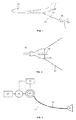
- the drogue 21 is released into the airstream and the drag D (see Figure 4 ) extends the hose 19.
- the control unit 41 is in charge of maintaining a constant extension speed of the hose 19 by controlling the drum device 35.
- a constant torque T oSTB is applied to the drum device 35, which is transmitted into a constant tension T eSTB at the hose 19. Brakes are also applied to the drum device 35.
- the To STB is fixed for every airspeed and should be lower than the theoretical drag D of the drogue 21, to keep a delta tension R i that eases the contact of the receiver aircraft 11.
- T oSTB values are traded-off for each type of drogue 21 and the pair T oSTB , D determines the flight envelope in which the hose&drogue device 17 can work.
- To STB is usually fixed at the beginning of the design phases and cannot be modified afterwards.
- the receiver aircraft 11 has to maneuver to make the contact.
- flight conditions such us turbulence
- the drogue 21 might be not stable so it creates an extra workload to the receiver pilot in order to perform the contact.
- missed contacts occur due to this drogue instability, with potential damages to both the receiver aircraft 11 and the hose&drogue device 17.
- Known refueling systems do not warn the receiver aircraft 11 whether the conditions for the contact are suitable or not.
- Another problem is that there is not feedback to the pilot of the receiver aircraft 11 with respect to the suitability of the hose&drogue device 17 to proceed to the connection.
- the probe 25 of the receiver aircraft 11 When the probe 25 of the receiver aircraft 11 is to disconnect, it pulls back the hose&drogue device 17 which is trailed in a controlled way following the receiver movement. If the hose&drogue device 17 is accelerated too fast or reaches the full extended position, the system applies brakes and the receiver aircraft 11 disengages.
- the receiver aircraft might disconnect when the hose 19 is not at full extended position (short hose event). It is needed, then, to apply a manual or automatic procedure to extend the hose 19.
- the automatic procedure is based on indirect measurements, such us partial torque relief. Those indirect measurements might lead to unintentional application of auto trail function while the receiver is in contact, which might create some oscillations in the hose 19. In other cases, when the receiver aircraft 11 is disconnected, the hose 19 might not be trailed if the tension release is not high enough to cope with the drogue drag and friction in the system.
- the hose&drogue device 17 When the refueling operation is finished, the hose&drogue device 17 is retracted. Usually, the hose&drogue device 17 is retracted by keeping a constant rotational speed of the drum.
- the hose&drogue in-flight refueling system of the invention comprises (see Figure 6 ):
- the sensing unit 37 comprises a triaxial accelerometer 53 inside the drogue 21 for measuring its acceleration and a piezoelectric load cell 51 placed between the drogue 21 and the hose 19 for measuring axial loads.
- the communication link 39 between the sensing unit 37 and the control unit 41 is a fiber optic line embedded inside the hose 19.
- the drogue is released into the airstream and is pulled back by the drag D.
- the tension R resultant over the end of the hose 19 (see Fig 4 ) is measured by the piezoelectric load cell 51 of the sensing unit 37. That tension R is controlled by the control unit 41 by sending commands to the drum device 35 to vary its torque T o to obtain a fixed deployment speed of the hose.
- the system By detecting variations over the required torque T o to extend/retract the hose 19, the system is also able to identify friction variations which can be stored in the control unit 41 for maintenance purposes.
- the piezoelectric load cell 51 sense the resultant tension R and the control unit 41 adapt the torque T o of the drum device 35 to achieve a tension value R i which eases the contact.
- drogue movements will be measured by the triaxial accelerometer 53 of the sensing unit 37. If those measurements overpass a predefined limit the receiver pilot will be informed (activating for example a red light placed at the end of the hose&drogue device 17) that the contact can end up in a missed one for preventing it.
- the sudden tension variation in the hose 19 is detected by the piezoelectric load cell 51 of the sensing unit 37 and the information is sent to the control unit 41 through the fiber optical line 39.
- the control unit 41 detects the contact and commands the drum device 35 to achieve a desirable force resultant R c (see Fig. 5 ). Commanding the torque T o of the drum device 35 generates a quicker response than a speed/position command and limits the risk of false contacts.
- the acceleration of the drogue 21 is also measured by the triaxial accelerometer 53 of the sensing unit 37. Therefore, the application of a torque T o to the drum device 35 to achieve R c can be adjusted to the acceleration needs. This adapts the application of the torque T o to the actual closure rate of the contact, assuring a smooth application for soft contacts and a faster reaction for higher closure rates.
- the control unit 41 keeps the suitable force resultant R c during the contact.
- the tension of the hose 19 is always kept in an optimum value.
- the torque T o will be accommodated to achieve R c and, therefore, no unexpected disconnections (due to high R c ) or hose sag (due to low R c ) will happen.
- the disconnection is detected by the sudden change in the forces (the drag D of the drogue 21 appears again).
- the system will detect it and will adjust the resultant tension R to allow a controlled hose extension to full trail position.
- the hose is always automatically trailed after the confirmation that the receiver aircraft has disconnected. Therefore, there will not be any inadvertent activation of the auto-trail function during the Phase 3: Receiver in contact.
- the system modifies the torque T o to achieve a desirable resultant tension R, the hose 19 will be always full trailed, even if there are variations in the drag D of the drogue 21 or in the friction of the system with respect to the design conditions.
Landscapes
- Engineering & Computer Science (AREA)
- Aviation & Aerospace Engineering (AREA)
- Rigid Pipes And Flexible Pipes (AREA)
Claims (9)
- Verfahren zum Durchführen eines Betankungsbetriebs eines Empfängerflugzeugs (11) von einem Tankerflugzeug (13) mit einer Betankungsvorrichtung (15) während des Flugs;
wobei die Betankungsvorrichtung (15) aufweist: eine Schlauch- und Fangtrichtervorrichtung (17) zum Liefern von Kraftstoff, die von dem Tankerflugzeug (13) mit Hilfe einer Trommelvorrichtung (35) ausziehbar/einziehbar ist, und eine Sonde (25), die von dem Empfängerflugzeug (11) ausziehbar/einziehbar ist, um Kraftstoff zu empfangen;
wobei die Schlauch- und Fangtrichtervorrichtung (17) einen Schlauch (19), eine Empfangskopplungseinheit (23) an dem Ende des Schlauchs (19) und einen an der Empfangskopplungseinheit (23) angebrachten Fangtrichter (21) aufweist;
wobei der Betankungsbetrieb die folgenden Phasen aufweist: "Schlauchausziehen", "Empfängemerbinden", "Empfänger in Kontakt", "Trennung und Rückkehr in die Kontaktbereitschaftsposition";
dadurch gekennzeichnet, dass er ein Steuerverfahren für die Bewegung der Schlauch- und Fangtrichtervorrichtung (17) umfasst, das die folgenden Schritte aufweist:a) kontinuierliches Messen der Spannung R am Ende des Schlauchs (19), die sich aus den auf den Fangtrichter (21) ausgeübten Kräften und aus der Spannung Te, die von der Trommelvorrichtung (35) auf den Schlauch (19) ausgeübt wird, ergibt;b) Verwenden der Messungen der Spannung R am Ende des Schlauchs (19), um das auf die Trommelvorrichtung (35) angewendete Drehmoment To derart zu steuern, dass die Spannung R am Ende des Schlauchs (19) in jeder Phase des Betankungsbetriebs Zielwerte erreicht. - Verfahren nach Anspruch 1, das ferner die folgenden Schritte in der "Schlauchausziehphase" aufweist:c) fortlaufendes Messen der Beschleunigung des Fangtrichters (21);d) Verwenden der Messungen der Beschleunigung des Fangtrichters (21), um unpassende Bedingungen für eine Verbindung mit dem Empfängerflugzeug zu erfassen.
- Verfahren nach einem der Ansprüche 1 - 2, wobei eine plötzliche Änderung der Messungen der Spannung R am Ende des Schlauchs (19) während der Phasen "Empfängerverbindung" und "Trennung und Rückkehr in die Kontaktbereitschaftsposition" in Schritt b) verwendet wird, um jeweils die Verbindung und Trennung der Schlauch- und Fangtrichtervorrichtung (17) mit/von der Sonde (25) zu erfassen und schnell mit der erforderlichen Änderung des auf die Trommelvorrichtung (35) angewendeten Drehmoments To weiter zu machen, um die Zielwerte der Spannung R an dem Ende des Schlauchs (19) zu erreichen.
- Betankungssystem während des Flugs, das ein Tankerflugzeug (13), ein Empfängerflugzeug (11) und eine Betankungsvorrichtung (15) aufweist;
wobei die Betankungsvorrichtung (15) aufweist: eine Schlauch- und Fangtrichtervorrichtung (17) zum Liefern von Kraftstoff, die von dem Tankerflugzeug (13) mit Hilfe einer Trommelvorrichtung (35) ausziehbar/einziehbar ist, und eine Sonde (25), die von dem Empfängerflugzeug (11) ausziehbar/einziehbar ist, um Kraftstoff zu empfangen;
wobei die Schlauch- und Fangtrichtervorrichtung (17) einen Schlauch (19), eine Empfangskopplungseinheit (23) am Ende des Schlauchs (19) und einen an der Empfangskopplungseinheit (23) angebrachten Fangtrichter (21) aufweist;
dadurch gekennzeichnet, dass es ferner aufweist:- eine Abtasteinheit (37), die fähig ist, während eines Betankungsbetriebs die Spannung R am Ende des Schlauchs (19), die sich aus den auf den Fangtrichter (21) ausgeübten Kräften und aus der Spannung Te, die von der Trommelvorrichtung (35) auf den Schlauch (19) ausgeübt wird, ergibt, fortlaufend zu messen;- eine Steuereinheit (41), die durch eine Kommunikationsverbindung (39) betriebsfähig mit der Abtasteinheit (37) und der Trommelvorrichtung (35) verbunden ist und geeignet ist, die Messungen der Spannung R am Ende des Schlauchs (19) zu verwenden, um das auf die Trommelvorrichtung (35) ausgeübte Drehmoment To derart zu steuern, dass die Spannung R am Ende des Schlauchs (19) in jeder Phase des Betankungsbetriebs Zielwerte erreicht. - Betankungssystem während des Flugs nach Anspruch 4, wobei:- die Abtasteinheit (37) auch fähig ist, die Beschleunigung des Fangtrichters (21) fortlaufend zu messen;die Steuereinheit (41) auch geeignet ist, die Messungen der Beschleunigung des Fangtrichters (21) zu verwenden, um unpassende Bedingungen für eine Verbindung mit dem Empfängerflugzeug (11) zu erfassen.
- Betankungssystem während des Flugs nach Anspruch 5, wobei die Schlauch- und Fangtrichtervorrichtung (17) eine Beleuchtungsvorrichtung aufweist, die betriebsfähig mit der Steuereinheit (41) verbunden ist, so dass sie aktiviert werden kann, um den Piloten des Empfängerflugzeugs (11) über unpassende Bedingungen für eine Verbindung zu informieren.
- Betankungssystem während des Flugs nach einem der Ansprüche 4 - 6, wobei die Abtasteinheit (37) eine piezoelektrische Lastzelle (51) zum fortlaufenden Messen der Spannung R am Ende des Schlauchs (19) aufweist.
- Betankungssystem während des Flugs nach einem der Ansprüche 5 - 7, wobei die Abtasteinheit (37) einen dreiachsigen Beschleunigungsmesser (53) zum fortlaufenden Messen der Beschleunigung des Fangtrichters (21) aufweist.
- Betankungssystem während des Flugs nach einem der Ansprüche 4 - 8, wobei eine Kommunikationsverbindung (39) eine in den Schlauch eingebettete Lichtleitfaserleitung ist.
Priority Applications (2)
| Application Number | Priority Date | Filing Date | Title |
|---|---|---|---|
| EP14382082.7A EP2915751B1 (de) | 2014-03-07 | 2014-03-07 | Schlauch- und Fangtrichterverfahren zur Betankung während des Fluges mit verbesserter Steuerung der Schlauch- und Fangtrichterbewegung |
| US14/640,652 US9969502B2 (en) | 2014-03-07 | 2015-03-06 | In-flight refueling method and system for controlling motion of the hose and drogue |
Applications Claiming Priority (1)
| Application Number | Priority Date | Filing Date | Title |
|---|---|---|---|
| EP14382082.7A EP2915751B1 (de) | 2014-03-07 | 2014-03-07 | Schlauch- und Fangtrichterverfahren zur Betankung während des Fluges mit verbesserter Steuerung der Schlauch- und Fangtrichterbewegung |
Publications (2)
| Publication Number | Publication Date |
|---|---|
| EP2915751A1 EP2915751A1 (de) | 2015-09-09 |
| EP2915751B1 true EP2915751B1 (de) | 2016-09-28 |
Family
ID=51059395
Family Applications (1)
| Application Number | Title | Priority Date | Filing Date |
|---|---|---|---|
| EP14382082.7A Active EP2915751B1 (de) | 2014-03-07 | 2014-03-07 | Schlauch- und Fangtrichterverfahren zur Betankung während des Fluges mit verbesserter Steuerung der Schlauch- und Fangtrichterbewegung |
Country Status (2)
| Country | Link |
|---|---|
| US (1) | US9969502B2 (de) |
| EP (1) | EP2915751B1 (de) |
Families Citing this family (9)
| Publication number | Priority date | Publication date | Assignee | Title |
|---|---|---|---|---|
| IL253015B2 (en) * | 2017-06-18 | 2023-07-01 | Israel Aerospace Ind Ltd | System and method for refueling aerial vehicles |
| IL253407B (en) | 2017-07-10 | 2020-08-31 | Israel Aerospace Ind Ltd | refueling station |
| US10332294B2 (en) * | 2017-08-16 | 2019-06-25 | The Boeing Company | Methods and systems for head up display (HUD) of aerial refueling operation status and signaling |
| GB2574078B (en) * | 2018-09-27 | 2020-05-20 | pitman James | Methods and systems for in-flight fuelling of aircraft |
| GB2569690B (en) * | 2018-10-26 | 2020-01-01 | pitman James | Fuel hose assembly for in-flight fuelling of aircraft |
| EP3680178B1 (de) * | 2019-01-14 | 2023-06-07 | Airbus Defence and Space, S.A.U. | Luftbetankungsschlauchspannungssteuerung |
| GB2586641A (en) * | 2019-08-30 | 2021-03-03 | Cobham Mission Systems Wimborne Ltd | Hose inspection system |
| CN113335559B (zh) * | 2021-06-01 | 2023-08-04 | 中国航空工业集团公司沈阳飞机设计研究所 | 一种空中加油软管锥套动态的模拟方法 |
| US12545426B2 (en) * | 2023-08-02 | 2026-02-10 | The Boeing Company | Systems and methods for a hose reel |
Family Cites Families (11)
| Publication number | Priority date | Publication date | Assignee | Title |
|---|---|---|---|---|
| US2692102A (en) * | 1949-04-01 | 1954-10-19 | Flight Refueling Ltd | Apparatus for towing and refueling aircraft in flight |
| US2879017A (en) * | 1955-01-25 | 1959-03-24 | Flight Refueling Inc | Apparatus for interconnecting aircraft in flight |
| US3289473A (en) * | 1964-07-14 | 1966-12-06 | Zd Y V I Plzen Narodni Podnik | Tension measuring apparatus |
| US4569489A (en) * | 1984-04-27 | 1986-02-11 | Joy Manufacturing Company | Cable tension control device |
| US4504023A (en) * | 1984-05-23 | 1985-03-12 | The United States Of America As Represented By The United States Department Of Energy | Apparatus producing constant cable tension for intermittent demand |
| US6866228B2 (en) * | 2000-07-21 | 2005-03-15 | Asher Bartov | Aerial refueling hose reel drive controlled by a variable displacement hydraulic motor and method for controlling aerial refueling hose reel |
| US7137598B2 (en) | 2004-08-26 | 2006-11-21 | The Boeing Company | In-flight refueling system, sensor system and method for damping oscillations in in-flight refueling system components |
| US20100072320A1 (en) * | 2008-09-24 | 2010-03-25 | Asher Bartov | Programmable aerial refueling range |
| GB2500669B (en) * | 2012-03-29 | 2016-03-30 | Icon Polymer Group | Hose for conveying fluid |
| EP2876052A1 (de) * | 2013-11-25 | 2015-05-27 | EADS Construcciones Aeronauticas S.A. | Luftbetankungssystem mit Betankungsschlauch und -korb mit einer aktiven Kraftstoffdrucksteuerung |
| WO2016200437A1 (en) * | 2015-06-11 | 2016-12-15 | Reel Power Licensing Corp. | Self-adjusting reel assembly apparatus, system and method |
-
2014
- 2014-03-07 EP EP14382082.7A patent/EP2915751B1/de active Active
-
2015
- 2015-03-06 US US14/640,652 patent/US9969502B2/en active Active
Also Published As
| Publication number | Publication date |
|---|---|
| US9969502B2 (en) | 2018-05-15 |
| EP2915751A1 (de) | 2015-09-09 |
| US20150251769A1 (en) | 2015-09-10 |
Similar Documents
| Publication | Publication Date | Title |
|---|---|---|
| EP2915751B1 (de) | Schlauch- und Fangtrichterverfahren zur Betankung während des Fluges mit verbesserter Steuerung der Schlauch- und Fangtrichterbewegung | |
| US6866228B2 (en) | Aerial refueling hose reel drive controlled by a variable displacement hydraulic motor and method for controlling aerial refueling hose reel | |
| EP2734446B1 (de) | Vorrichtung für ein luftbetankungssystem | |
| US6454212B1 (en) | Aerial refueling hose reel drive controlled by a variable displacement hydraulic motor and method for controlling aerial refueling hose reel | |
| JP4934023B2 (ja) | 風力船舶の自由に飛行する凧タイプの風を受ける要素の位置決めデバイス | |
| KR102166624B1 (ko) | 비행체들을 재급유하는 디바이스들, 시스템들 및 방법들 | |
| CN101687537B (zh) | 气动风力推进设备及控制方法 | |
| US20100072320A1 (en) | Programmable aerial refueling range | |
| EP1789321B1 (de) | System zum betanken während des fluges, sensorsystem und verfahren zur schwingungsdämpfung für komponenten eines systems zum betanken während des fluges | |
| KR102608506B1 (ko) | 공중 비행체 급유를 위한 시스템 및 방법 | |
| US20230242270A1 (en) | Air to air active refueling system and method for generating aerodynamic radial loads at a hose-end | |
| CN112823123A (zh) | 飞机飞行中加油的方法和系统 | |
| EP3459856B1 (de) | Steuerungssysteme und -verfahren für teleskopischen betankungsausleger | |
| US11987351B2 (en) | Tow line tension management systems for aircraft | |
| US20150284107A1 (en) | Hose&drogue in-flight refueling system with an active fuel pressure control | |
| EP3680178B1 (de) | Luftbetankungsschlauchspannungssteuerung | |
| CN106767181B (zh) | 一种航空外挂靶标短舱 | |
| CN109795710A (zh) | 系留无人机同步控制的全自动收放线系统 | |
| US8328139B2 (en) | Method and device for in-flight refuelling operations using a boom | |
| CN206387315U (zh) | 一种航空外挂靶标短舱 | |
| CN119160393A (zh) | 一种用于大型航天器空中回收的装置及控制方法 |
Legal Events
| Date | Code | Title | Description |
|---|---|---|---|
| PUAI | Public reference made under article 153(3) epc to a published international application that has entered the european phase |
Free format text: ORIGINAL CODE: 0009012 |
|
| AK | Designated contracting states |
Kind code of ref document: A1 Designated state(s): AL AT BE BG CH CY CZ DE DK EE ES FI FR GB GR HR HU IE IS IT LI LT LU LV MC MK MT NL NO PL PT RO RS SE SI SK SM TR |
|
| AX | Request for extension of the european patent |
Extension state: BA ME |
|
| RAP1 | Party data changed (applicant data changed or rights of an application transferred) |
Owner name: AIRBUS DEFENCE AND SPACE SA |
|
| 17P | Request for examination filed |
Effective date: 20160303 |
|
| RBV | Designated contracting states (corrected) |
Designated state(s): AL AT BE BG CH CY CZ DE DK EE ES FI FR GB GR HR HU IE IS IT LI LT LU LV MC MK MT NL NO PL PT RO RS SE SI SK SM TR |
|
| GRAP | Despatch of communication of intention to grant a patent |
Free format text: ORIGINAL CODE: EPIDOSNIGR1 |
|
| INTG | Intention to grant announced |
Effective date: 20160422 |
|
| GRAS | Grant fee paid |
Free format text: ORIGINAL CODE: EPIDOSNIGR3 |
|
| GRAA | (expected) grant |
Free format text: ORIGINAL CODE: 0009210 |
|
| AK | Designated contracting states |
Kind code of ref document: B1 Designated state(s): AL AT BE BG CH CY CZ DE DK EE ES FI FR GB GR HR HU IE IS IT LI LT LU LV MC MK MT NL NO PL PT RO RS SE SI SK SM TR |
|
| REG | Reference to a national code |
Ref country code: GB Ref legal event code: FG4D |
|
| REG | Reference to a national code |
Ref country code: CH Ref legal event code: EP |
|
| REG | Reference to a national code |
Ref country code: AT Ref legal event code: REF Ref document number: 832503 Country of ref document: AT Kind code of ref document: T Effective date: 20161015 |
|
| REG | Reference to a national code |
Ref country code: IE Ref legal event code: FG4D |
|
| REG | Reference to a national code |
Ref country code: DE Ref legal event code: R096 Ref document number: 602014003983 Country of ref document: DE |
|
| REG | Reference to a national code |
Ref country code: LT Ref legal event code: MG4D |
|
| PG25 | Lapsed in a contracting state [announced via postgrant information from national office to epo] |
Ref country code: HR Free format text: LAPSE BECAUSE OF FAILURE TO SUBMIT A TRANSLATION OF THE DESCRIPTION OR TO PAY THE FEE WITHIN THE PRESCRIBED TIME-LIMIT Effective date: 20160928 Ref country code: LT Free format text: LAPSE BECAUSE OF FAILURE TO SUBMIT A TRANSLATION OF THE DESCRIPTION OR TO PAY THE FEE WITHIN THE PRESCRIBED TIME-LIMIT Effective date: 20160928 Ref country code: NO Free format text: LAPSE BECAUSE OF FAILURE TO SUBMIT A TRANSLATION OF THE DESCRIPTION OR TO PAY THE FEE WITHIN THE PRESCRIBED TIME-LIMIT Effective date: 20161228 Ref country code: RS Free format text: LAPSE BECAUSE OF FAILURE TO SUBMIT A TRANSLATION OF THE DESCRIPTION OR TO PAY THE FEE WITHIN THE PRESCRIBED TIME-LIMIT Effective date: 20160928 Ref country code: FI Free format text: LAPSE BECAUSE OF FAILURE TO SUBMIT A TRANSLATION OF THE DESCRIPTION OR TO PAY THE FEE WITHIN THE PRESCRIBED TIME-LIMIT Effective date: 20160928 |
|
| REG | Reference to a national code |
Ref country code: NL Ref legal event code: MP Effective date: 20160928 |
|
| REG | Reference to a national code |
Ref country code: AT Ref legal event code: MK05 Ref document number: 832503 Country of ref document: AT Kind code of ref document: T Effective date: 20160928 |
|
| PG25 | Lapsed in a contracting state [announced via postgrant information from national office to epo] |
Ref country code: LV Free format text: LAPSE BECAUSE OF FAILURE TO SUBMIT A TRANSLATION OF THE DESCRIPTION OR TO PAY THE FEE WITHIN THE PRESCRIBED TIME-LIMIT Effective date: 20160928 Ref country code: GR Free format text: LAPSE BECAUSE OF FAILURE TO SUBMIT A TRANSLATION OF THE DESCRIPTION OR TO PAY THE FEE WITHIN THE PRESCRIBED TIME-LIMIT Effective date: 20161229 Ref country code: SE Free format text: LAPSE BECAUSE OF FAILURE TO SUBMIT A TRANSLATION OF THE DESCRIPTION OR TO PAY THE FEE WITHIN THE PRESCRIBED TIME-LIMIT Effective date: 20160928 Ref country code: NL Free format text: LAPSE BECAUSE OF FAILURE TO SUBMIT A TRANSLATION OF THE DESCRIPTION OR TO PAY THE FEE WITHIN THE PRESCRIBED TIME-LIMIT Effective date: 20160928 |
|
| REG | Reference to a national code |
Ref country code: FR Ref legal event code: PLFP Year of fee payment: 4 |
|
| PG25 | Lapsed in a contracting state [announced via postgrant information from national office to epo] |
Ref country code: RO Free format text: LAPSE BECAUSE OF FAILURE TO SUBMIT A TRANSLATION OF THE DESCRIPTION OR TO PAY THE FEE WITHIN THE PRESCRIBED TIME-LIMIT Effective date: 20160928 Ref country code: EE Free format text: LAPSE BECAUSE OF FAILURE TO SUBMIT A TRANSLATION OF THE DESCRIPTION OR TO PAY THE FEE WITHIN THE PRESCRIBED TIME-LIMIT Effective date: 20160928 |
|
| PG25 | Lapsed in a contracting state [announced via postgrant information from national office to epo] |
Ref country code: PT Free format text: LAPSE BECAUSE OF FAILURE TO SUBMIT A TRANSLATION OF THE DESCRIPTION OR TO PAY THE FEE WITHIN THE PRESCRIBED TIME-LIMIT Effective date: 20170130 Ref country code: AT Free format text: LAPSE BECAUSE OF FAILURE TO SUBMIT A TRANSLATION OF THE DESCRIPTION OR TO PAY THE FEE WITHIN THE PRESCRIBED TIME-LIMIT Effective date: 20160928 Ref country code: SM Free format text: LAPSE BECAUSE OF FAILURE TO SUBMIT A TRANSLATION OF THE DESCRIPTION OR TO PAY THE FEE WITHIN THE PRESCRIBED TIME-LIMIT Effective date: 20160928 Ref country code: BE Free format text: LAPSE BECAUSE OF FAILURE TO SUBMIT A TRANSLATION OF THE DESCRIPTION OR TO PAY THE FEE WITHIN THE PRESCRIBED TIME-LIMIT Effective date: 20160928 Ref country code: ES Free format text: LAPSE BECAUSE OF FAILURE TO SUBMIT A TRANSLATION OF THE DESCRIPTION OR TO PAY THE FEE WITHIN THE PRESCRIBED TIME-LIMIT Effective date: 20160928 Ref country code: IS Free format text: LAPSE BECAUSE OF FAILURE TO SUBMIT A TRANSLATION OF THE DESCRIPTION OR TO PAY THE FEE WITHIN THE PRESCRIBED TIME-LIMIT Effective date: 20170128 Ref country code: SK Free format text: LAPSE BECAUSE OF FAILURE TO SUBMIT A TRANSLATION OF THE DESCRIPTION OR TO PAY THE FEE WITHIN THE PRESCRIBED TIME-LIMIT Effective date: 20160928 Ref country code: BG Free format text: LAPSE BECAUSE OF FAILURE TO SUBMIT A TRANSLATION OF THE DESCRIPTION OR TO PAY THE FEE WITHIN THE PRESCRIBED TIME-LIMIT Effective date: 20161228 Ref country code: PL Free format text: LAPSE BECAUSE OF FAILURE TO SUBMIT A TRANSLATION OF THE DESCRIPTION OR TO PAY THE FEE WITHIN THE PRESCRIBED TIME-LIMIT Effective date: 20160928 Ref country code: CZ Free format text: LAPSE BECAUSE OF FAILURE TO SUBMIT A TRANSLATION OF THE DESCRIPTION OR TO PAY THE FEE WITHIN THE PRESCRIBED TIME-LIMIT Effective date: 20160928 |
|
| REG | Reference to a national code |
Ref country code: DE Ref legal event code: R097 Ref document number: 602014003983 Country of ref document: DE |
|
| PG25 | Lapsed in a contracting state [announced via postgrant information from national office to epo] |
Ref country code: IT Free format text: LAPSE BECAUSE OF FAILURE TO SUBMIT A TRANSLATION OF THE DESCRIPTION OR TO PAY THE FEE WITHIN THE PRESCRIBED TIME-LIMIT Effective date: 20160928 |
|
| PG25 | Lapsed in a contracting state [announced via postgrant information from national office to epo] |
Ref country code: DK Free format text: LAPSE BECAUSE OF FAILURE TO SUBMIT A TRANSLATION OF THE DESCRIPTION OR TO PAY THE FEE WITHIN THE PRESCRIBED TIME-LIMIT Effective date: 20160928 |
|
| PLBE | No opposition filed within time limit |
Free format text: ORIGINAL CODE: 0009261 |
|
| STAA | Information on the status of an ep patent application or granted ep patent |
Free format text: STATUS: NO OPPOSITION FILED WITHIN TIME LIMIT |
|
| 26N | No opposition filed |
Effective date: 20170629 |
|
| REG | Reference to a national code |
Ref country code: DE Ref legal event code: R119 Ref document number: 602014003983 Country of ref document: DE |
|
| REG | Reference to a national code |
Ref country code: CH Ref legal event code: PL |
|
| PG25 | Lapsed in a contracting state [announced via postgrant information from national office to epo] |
Ref country code: MC Free format text: LAPSE BECAUSE OF FAILURE TO SUBMIT A TRANSLATION OF THE DESCRIPTION OR TO PAY THE FEE WITHIN THE PRESCRIBED TIME-LIMIT Effective date: 20160928 Ref country code: SI Free format text: LAPSE BECAUSE OF FAILURE TO SUBMIT A TRANSLATION OF THE DESCRIPTION OR TO PAY THE FEE WITHIN THE PRESCRIBED TIME-LIMIT Effective date: 20160928 |
|
| REG | Reference to a national code |
Ref country code: IE Ref legal event code: MM4A |
|
| PG25 | Lapsed in a contracting state [announced via postgrant information from national office to epo] |
Ref country code: LU Free format text: LAPSE BECAUSE OF NON-PAYMENT OF DUE FEES Effective date: 20170307 Ref country code: DE Free format text: LAPSE BECAUSE OF NON-PAYMENT OF DUE FEES Effective date: 20171003 |
|
| PG25 | Lapsed in a contracting state [announced via postgrant information from national office to epo] |
Ref country code: CH Free format text: LAPSE BECAUSE OF NON-PAYMENT OF DUE FEES Effective date: 20170331 Ref country code: IE Free format text: LAPSE BECAUSE OF NON-PAYMENT OF DUE FEES Effective date: 20170307 Ref country code: LI Free format text: LAPSE BECAUSE OF NON-PAYMENT OF DUE FEES Effective date: 20170331 |
|
| REG | Reference to a national code |
Ref country code: FR Ref legal event code: PLFP Year of fee payment: 5 |
|
| PG25 | Lapsed in a contracting state [announced via postgrant information from national office to epo] |
Ref country code: MT Free format text: LAPSE BECAUSE OF NON-PAYMENT OF DUE FEES Effective date: 20170307 |
|
| PG25 | Lapsed in a contracting state [announced via postgrant information from national office to epo] |
Ref country code: AL Free format text: LAPSE BECAUSE OF FAILURE TO SUBMIT A TRANSLATION OF THE DESCRIPTION OR TO PAY THE FEE WITHIN THE PRESCRIBED TIME-LIMIT Effective date: 20160928 |
|
| PG25 | Lapsed in a contracting state [announced via postgrant information from national office to epo] |
Ref country code: HU Free format text: LAPSE BECAUSE OF FAILURE TO SUBMIT A TRANSLATION OF THE DESCRIPTION OR TO PAY THE FEE WITHIN THE PRESCRIBED TIME-LIMIT; INVALID AB INITIO Effective date: 20140307 |
|
| PG25 | Lapsed in a contracting state [announced via postgrant information from national office to epo] |
Ref country code: CY Free format text: LAPSE BECAUSE OF FAILURE TO SUBMIT A TRANSLATION OF THE DESCRIPTION OR TO PAY THE FEE WITHIN THE PRESCRIBED TIME-LIMIT Effective date: 20160928 |
|
| PG25 | Lapsed in a contracting state [announced via postgrant information from national office to epo] |
Ref country code: MK Free format text: LAPSE BECAUSE OF FAILURE TO SUBMIT A TRANSLATION OF THE DESCRIPTION OR TO PAY THE FEE WITHIN THE PRESCRIBED TIME-LIMIT Effective date: 20160928 |
|
| PG25 | Lapsed in a contracting state [announced via postgrant information from national office to epo] |
Ref country code: TR Free format text: LAPSE BECAUSE OF FAILURE TO SUBMIT A TRANSLATION OF THE DESCRIPTION OR TO PAY THE FEE WITHIN THE PRESCRIBED TIME-LIMIT Effective date: 20160928 |
|
| PGFP | Annual fee paid to national office [announced via postgrant information from national office to epo] |
Ref country code: GB Payment date: 20260324 Year of fee payment: 13 |
|
| PGFP | Annual fee paid to national office [announced via postgrant information from national office to epo] |
Ref country code: FR Payment date: 20260320 Year of fee payment: 13 |